JP4467932B2 - Inner blade assembly, razor device, and method of shaving using razor device - Google Patents
Inner blade assembly, razor device, and method of shaving using razor device Download PDFInfo
- Publication number
- JP4467932B2 JP4467932B2 JP2003321926A JP2003321926A JP4467932B2 JP 4467932 B2 JP4467932 B2 JP 4467932B2 JP 2003321926 A JP2003321926 A JP 2003321926A JP 2003321926 A JP2003321926 A JP 2003321926A JP 4467932 B2 JP4467932 B2 JP 4467932B2
- Authority
- JP
- Japan
- Prior art keywords
- inner blade
- blade
- assembly
- razor
- blade assembly
- Prior art date
- Legal status (The legal status is an assumption and is not a legal conclusion. Google has not performed a legal analysis and makes no representation as to the accuracy of the status listed.)
- Expired - Lifetime
Links
Images


Classifications
-
- B—PERFORMING OPERATIONS; TRANSPORTING
- B26—HAND CUTTING TOOLS; CUTTING; SEVERING
- B26B—HAND-HELD CUTTING TOOLS NOT OTHERWISE PROVIDED FOR
- B26B19/00—Clippers or shavers operating with a plurality of cutting edges, e.g. hair clippers, dry shavers
- B26B19/02—Clippers or shavers operating with a plurality of cutting edges, e.g. hair clippers, dry shavers of the reciprocating-cutter type
- B26B19/04—Cutting heads therefor; Cutters therefor; Securing equipment thereof
- B26B19/042—Long hair cutters or older types comprising a cutting grid
-
- B—PERFORMING OPERATIONS; TRANSPORTING
- B26—HAND CUTTING TOOLS; CUTTING; SEVERING
- B26B—HAND-HELD CUTTING TOOLS NOT OTHERWISE PROVIDED FOR
- B26B19/00—Clippers or shavers operating with a plurality of cutting edges, e.g. hair clippers, dry shavers
- B26B19/02—Clippers or shavers operating with a plurality of cutting edges, e.g. hair clippers, dry shavers of the reciprocating-cutter type
- B26B19/04—Cutting heads therefor; Cutters therefor; Securing equipment thereof
- B26B19/044—Manufacture and assembly of cutter blocks
-
- Y—GENERAL TAGGING OF NEW TECHNOLOGICAL DEVELOPMENTS; GENERAL TAGGING OF CROSS-SECTIONAL TECHNOLOGIES SPANNING OVER SEVERAL SECTIONS OF THE IPC; TECHNICAL SUBJECTS COVERED BY FORMER USPC CROSS-REFERENCE ART COLLECTIONS [XRACs] AND DIGESTS
- Y10—TECHNICAL SUBJECTS COVERED BY FORMER USPC
- Y10T—TECHNICAL SUBJECTS COVERED BY FORMER US CLASSIFICATION
- Y10T83/00—Cutting
- Y10T83/04—Processes
Landscapes
- Engineering & Computer Science (AREA)
- Life Sciences & Earth Sciences (AREA)
- Forests & Forestry (AREA)
- Mechanical Engineering (AREA)
- Manufacturing & Machinery (AREA)
- Dry Shavers And Clippers (AREA)
- Knives (AREA)
Abstract
Description
本発明は剃刀装置、および人間の皮膚の毛を剃る方法に関する。 The present invention relates to a razor device and a method for shaving human skin hair.
剃刀ないし電気剃刀のように毛を切断しあるいは剃るための道具は、従来技術において周知である。人間の顔の毛を剃るためのほとんどの従来技術の剃刀用の道具は皮膚表面の近傍で、好ましくは皮膚に傷をつけあるいは皮膚を切ることなしに、皮膚の表面より下側で毛を切断するように設計されている。 Tools for cutting or shaving hair, such as razors or electric razors, are well known in the prior art. Most prior art razor tools for shaving human face hair cut hair near the surface of the skin, preferably below the surface of the skin without damaging or cutting the skin Designed to be.
従来の電動剃刀装置は一般的に個々の毛を複数の小さな部分に切断しており、粉末状の破片(屑)につながっていた。さらに、その結果として剃られた皮膚には完全に満足できる方法では切断されなかった切り株状の毛が残っている。 The conventional electric razor apparatus generally cuts individual hairs into a plurality of small parts, which are connected to powdered pieces (debris). Furthermore, the resulting shaved skin remains stump-like hair that has not been cut in a completely satisfactory manner.
この課題を解決するために様々な試みがなされてきた。例えば、ドライタイプ(乾式)の電気剃刀が特許文献1(Buras, Jr.)に開示されている。この電気剃刀は、低く横たわっている顔の毛を、刃ブロック上に隠れている刃によって切断するために動かして持ち上げる突起物を、網刃の外側表面上に有している。この刃ブロックは、当該刃ブロックをアンバランスなものにして振動させ、特に横方向に動かすための錘を有しているが、この錘はハウジングおよび網刃の振動をも生じさせる。 Various attempts have been made to solve this problem. For example, a dry type (dry type) electric razor is disclosed in Patent Document 1 (Buras, Jr.). The electric razor has protrusions on the outer surface of the mesh blade that move and lift the low lying facial hair to cut by the blade hidden on the blade block. The blade block has a weight for vibrating the blade block in an unbalanced manner, and in particular moving the blade block in the lateral direction. The weight also causes vibration of the housing and the mesh blade.
また、特許文献2(Wellinger)は、軸線方向に整列させて取り付けられている2つのカッタ部分を備えた電気剃刀を記載している。これらの2つのカッタ部分は直線往復運動のためにそれらの末端同士が隣り合うように取り付けられ、ユーザーへの不快な振動の伝達を防止するとともに剃刀が皮膚に接触する箇所における振動に起因する不快な感覚を防止するようになっている。 Moreover, patent document 2 (Wellinger) has described the electric razor provided with the two cutter parts attached in alignment with an axial direction. These two cutter parts are mounted so that their ends are adjacent to each other for linear reciprocation, preventing transmission of unpleasant vibrations to the user and uncomfortable due to vibrations where the razor contacts the skin. It is designed to prevent nasty sensations.
さらに、特許文献3(Wellinger)は、2つのカッタ部分を備えた電気剃刀を開示しているが、これらのカッタ部分は長手方向にかつ互いに平行に延びており、快適性および騒音上の理由から使用中における剃刀本体の振動を防止するばかりでなく、バッテリ寿命を延長するようになっている。2つのカッタ部分は、2つのコイルばねによって互いに離間するように常に付勢されている。 Furthermore, Patent Document 3 (Wellinger) discloses an electric razor with two cutter parts, which extend in the longitudinal direction and parallel to each other for reasons of comfort and noise. In addition to preventing vibration of the razor body during use, it also extends battery life. The two cutter parts are always urged away from each other by two coil springs.
また、特許文献4(Klein)は、2つの内側カッタを備えたドライタイプの剃刀装置を記載しているが、これらの内側カッタは、共通の外刃と作動的に関連するとともに、振動および作動時の騒音を防止するために相対的に反対方向に、かつ少なくとも1つのばね要素の力に抗するように、それぞれが1つの駆動要素によって駆動される。交互に平行に配置された両方の内側カッタに作用するばね要素は、内側カッタの振動に対して永続的な補償を与えている。 Further, Patent Document 4 (Klein) describes a dry-type razor device having two inner cutters, and these inner cutters are operatively associated with a common outer blade, and are vibrated and operated. Each is driven by one drive element in a relatively opposite direction to prevent time noise and against the force of at least one spring element. Spring elements acting on both inner cutters arranged alternately in parallel provide permanent compensation for the vibration of the inner cutter.
特許文献5(Heyek)は、ドライタイプの剃刀装置を開示しているが、そのモータによって引き起こされる機械的な振動からできる限り逃れるために、2つの独立したカッタはそれぞれ復元ばねに抗して駆動されている。 Patent document 5 (Heyek) discloses a dry-type razor device, but in order to escape as much as possible from the mechanical vibration caused by the motor, the two independent cutters are driven against the restoring springs, respectively. Has been.
さらに、特許文献6は、軸線方向に整列配置されて逆方向に駆動される2つの内刃を開示しているが、その各ガイドブロックの一部は案内のために互いに係合している。 Furthermore, Patent Document 6 discloses two inner blades that are aligned in the axial direction and driven in opposite directions, and a part of each guide block is engaged with each other for guidance.
最後に、特許文献7(Page)は、端部同士が対向するように軸線方向に位置合わせされるとともにかさ歯車構造によって反対方向に回転する二つの内刃を備えたドライタイプの剃刀装置を開示している。しかしながら、従来の剃刀装置は、しばしば、剃った後の皮膚にかなりの長さの切り株状の毛を残してしまうため、短い期間の後には剃っていないよう見えてしまう。
本発明の目的は、駆動モータの速度を増加させる必要がない単純な方法で切断イベント(事象)ないし潜在的な切断イベントの数を増加させることによって切断効率を改善することにある。 It is an object of the present invention to improve cutting efficiency by increasing the number of cutting events or potential cutting events in a simple manner without having to increase the speed of the drive motor.
本発明の1つの態様によると、複数の開口を有している外刃と、前記外刃に隣接する内刃組立体と、前記内刃組立体を往復運動方向に交互に動かすためのモータと、を備え、前記内刃組立体は第1の内刃および第2の内刃を有し、それら第1および第2の内刃の刃エレメントが交互に並ぶように配設されており、前記第1の内刃は前記往復運動方向に駆動されるように前記モータに連結され、前記第2の内刃は前記モーターから切り離され、かつ前記第1の内刃の往復運動に応答して前記往復運動方向において前記第1の内刃に対して動くように取り付けられていることを特徴とする剃刀装置が提供される。それらの交互に配置された刃エレメント間に毛を掴むとともに切断する前に掴んだ毛を引っ張るべく第1の内刃および第2の内刃が協動できるように、第2の内刃は、第1の内刃によって第1の内刃に対して遅れる関係で往復運動させられることが好ましい。2つの内刃の配置は、改良された皮膚への密着が得られるようなものであることが好ましい。第2の内刃が第1の内刃の内側に入れ子にされることが好ましいが、これは1つないし複数のばねのような付勢部材によって有利に達成することができる。いくつかの実施例においては、第2の内刃をばねによって第1の内刃に取り付けることができる。他の実施例においては、第2の内刃を支持ブロック上に、ないし網刃フレーム上に、あるいは剃刀ヘッドフレーム上に取り付けることができる。 According to one aspect of the present invention, an outer blade having a plurality of openings, an inner blade assembly adjacent to the outer blade, and a motor for alternately moving the inner blade assembly in a reciprocating direction. The inner blade assembly has a first inner blade and a second inner blade, and the blade elements of the first and second inner blades are arranged alternately, The first inner blade is coupled to the motor to be driven in the reciprocating direction, the second inner blade is disconnected from the motor, and the first inner blade is responsive to the reciprocating motion of the first inner blade. A razor device is provided that is mounted to move relative to the first inner blade in a reciprocating direction. The second inner blade is such that the first inner blade and the second inner blade can cooperate to grip the bristles between the alternating blade elements and pull the gripped hair before cutting. It is preferable that the first inner blade is reciprocated in a delayed relationship with respect to the first inner blade. The arrangement of the two inner blades is preferably such that improved adhesion to the skin is obtained. The second inner blade is preferably nested inside the first inner blade, but this can advantageously be achieved by a biasing member such as one or more springs. In some embodiments, the second inner blade can be attached to the first inner blade by a spring. In other embodiments, the second inner blade can be mounted on the support block, on the mesh blade frame, or on the razor head frame.
本発明の他の態様によると、外刃に接触させつつ内刃組立体を往復運動させる段階、前記内刃組立体の第1および第2の内刃の交互に配置された刃エレメント間に切断する毛を掴まえる段階、往復運動方向における前記内刃組立体の継続的な動きによって前記掴まえた毛を引っ張る段階、および前記外刃と前記内刃組立体との間で前記毛を切断する段階、を備えることを特徴とする毛剃り方法が提供される。 According to another aspect of the present invention, the step of reciprocating the inner blade assembly while being in contact with the outer blade, cutting between alternately disposed blade elements of the first and second inner blades of the inner blade assembly. Gripping the bristled hair, pulling the gripped hair by a continuous movement of the inner blade assembly in the reciprocating direction, and cutting the hair between the outer blade and the inner blade assembly The method for shaving is provided.
本発明の他の態様においては、元々の内刃組立体が切れなくなったり傷んだりしたときにドライタイプの剃刀内に組み付けられる、交換可能な部品として有用な内刃部分組立体が提供される。第2の内刃は、それらの刃が交互に配置されるとともに第2の内刃が第1の内刃に対して移動できるように、第1の内刃の内側に装着可能である。そのような内刃組立体はまた、電気剃刀の既存のモデルをアップグレードするための更新部品として供給することができる。第2の内刃は、第1の内刃に対して直接付勢することもできるし、内刃組立体を支持している支持体に対して付勢することによって第1の内刃とは独立して付勢することもできる。往復運動する第1の内刃が第2の内刃を動かし、好ましくは第1の内刃との関係において遅れるようにするひとつの方法が記載される。 In another aspect of the present invention, there is provided an inner blade subassembly useful as a replaceable part that can be assembled into a dry-type razor when the original inner blade assembly becomes uncut or damaged. The second inner blade can be mounted inside the first inner blade so that the blades are alternately arranged and the second inner blade can move relative to the first inner blade. Such an inner blade assembly can also be supplied as an update part for upgrading existing models of electric razors. The second inner blade can be biased directly with respect to the first inner blade, or the first inner blade can be biased against the support body supporting the inner blade assembly. It can also be activated independently. One method is described in which a reciprocating first inner blade moves a second inner blade, preferably delayed in relation to the first inner blade.
第1の内刃が往復運動方向に駆動されるときに、駆動されない第2の内刃の刃エレメントは、最初のうちは第1の内刃の刃エレメントに対して遅れる。それから、第1の内刃の刃エレメントは往復運動方向における第1の内刃の継続的な動きの結果として第2の内刃の刃エレメントに接触することができ、かつ第1のおよび第2の内刃の交互に配置された刃エレメント間に毛を捉えるが、このことが捕捉要素を形成する。その後、第2の内刃が往復運動方向に押動されて掴んだ毛がそれらの毛胞から多少引っ張られるように、第1の内刃がさらに動く。掴んだ毛を外刃と内刃組立体の隣接する刃エレメントとの間でせん断することによって切断するように、第1の内刃は、第1および第2の内刃の隣接する表面が外刃の切刃の下を通過するまで掴んだ毛と共に第2の内刃を押動する。その後、第1の内刃は、上記の手順を繰り返すためにその方向が逆転する。 When the first inner blade is driven in the reciprocating direction, the blade element of the second inner blade that is not driven is initially delayed with respect to the blade element of the first inner blade. Then, the blade element of the first inner blade can contact the blade element of the second inner blade as a result of the continuous movement of the first inner blade in the reciprocating direction, and the first and second The hair is caught between the alternately arranged blade elements of the inner blade, which forms the catching element. Thereafter, the first inner blade is further moved so that the second inner blade is pushed in the reciprocating direction and the gripped hair is pulled slightly from the follicles. The first inner blade has adjacent surfaces of the first and second inner blades so that the gripped hair is cut by shearing between the outer blade and the adjacent blade element of the inner blade assembly. The second inner blade is pushed together with the gripped hair until it passes under the blade. Thereafter, the direction of the first inner blade is reversed in order to repeat the above procedure.
切断する前に第1および第2の内刃の刃エレメント間に毛を掴んで引っ張ることにより、従来のドライタイプの剃刀に比較するとより大きな長さで剃屑を切断することができる。加えて、皮膚に残る切株状の毛はより短くなる。掴まれた毛が切断前に引っ張られるとともに残っている切株状の毛が切断後に(いわゆるヒステリシス効果によって)引っ込むからである。その結果、滑らかに剃られた皮膚が得られるような改良された皮膚への密着が達成される。 By grasping and pulling the hair between the blade elements of the first and second inner blades before cutting, the shavings can be cut in a longer length compared to a conventional dry type razor. In addition, the stump hair remaining on the skin is shorter. This is because the gripped hair is pulled before cutting and the remaining stump-like hair is retracted after cutting (by a so-called hysteresis effect). As a result, improved skin contact is achieved such that a smooth shaved skin is obtained.
以下、添付の図面を参照して本発明の実施例について説明する。 Hereinafter, embodiments of the present invention will be described with reference to the accompanying drawings.
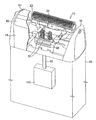
図1は、2つのカッタユニットを備えるタイプの剃刀ヘッドを示している。各カッタユニットは、それぞれ内刃組立体および外刃、すなわち網刃を有している。明瞭さのために、図1は網刃フレーム19に取り付けられている(従来の)外刃60、61の要部を破断して示している。第1の内刃組立体10は、組立てられた状態でその全体が示されている。第2内刃組立体は、その一部だけが示されている。
FIG. 1 shows a razor head of the type comprising two cutter units. Each cutter unit has an inner blade assembly and an outer blade, that is, a mesh blade. For the sake of clarity, FIG. 1 shows a cutaway view of the main parts of (conventional)
各内刃組立体10は、図1に示されているように、第1の内刃、第2の内刃、支持ブロック23、および好ましくは少なくとも2つのばね50を支持するサブマウント80を備えている。第2の内刃組立体については、サブマウント80および2つのばね50だけが示されている。1つないし複数のばね50の存在は本発明を実施するために必須ではないが、より良い剃刀効率のために好ましいと理解される。サブマウント80は駆動ブロックの一部であると理解されるが、この駆動ブロックは周知であるとともに従来通りにハンドルユニットハウジング98内のモータによって駆動軸99を介して駆動される。周知のように、サブマウント80は駆動部材、例えばピン90によって着脱自在に剃刀に取り付けられるが、この駆動部材は剃刀のドライブピンにサブマウント80を接続し、かつ図1Aに示されている、
Each
図1Aは、図1に示した第1および第2の内刃組立体を有した内刃ユニットを示している。図示されている組立体10のような各内刃組立体は共通のサブマウント80上に取り付けられているが、このサブマウント80はまた下方に垂れ下がっている駆動部材90をもたらしている。この駆動部材90は、一般的にピン部材として形成されるとともに、剃刀モーター100から駆動力を受け入れるために駆動ハウジング上の補完的な凹部と係合する。
FIG. 1A shows an inner blade unit having the first and second inner blade assemblies shown in FIG. Each inner blade assembly, such as the
図2は、支持ブロックが取り外された状態の、第1の内刃20および第2の内刃30を有した第1の内刃組立体10の斜視図である。第1の内刃20および第2の内刃30は、両方の要素を実質的に半分に分離する垂直面に沿った部分断面図として示されている。
FIG. 2 is a perspective view of the first
第1の内刃20は、その外側および内側の表面がそれぞれ実質的に半円筒状の形状を形成するように、一様に間隔が開けられるとともに環状の形態を有した複数の刃エレメント21を有している。第1の内刃20と同様に、第2の内刃30は、その外側および内側の表面がそれぞれ実質的に半円筒状の形状を形成するように、一様に間隔が開けられるとともに環状の形態を有した複数の刃エレメント31を有している。刃エレメント31は、第1の内刃の刃エレメント21に対して交互に配置されている。
図2は内刃組立体10の静止ないし中立位置を示しているが、第1の内刃の刃エレメント21および第2の内刃30の刃エレメント31は互いに等しい距離にある。刃エレメントの交互配置を達成するために、半円筒状の第2の内刃30が、第1の内刃20の半円筒状形状の内側に入れ子となるように構成されていることが理解される。
The first
FIG. 2 shows the stationary or neutral position of the
第1の内刃20に対する第2の内刃30の位置決めのために、一方においては第1の内刃20に連結されるとともに他方においては第2の内刃30に連結された第2のばね要素40が設けられている。この第2のばね要素40は好ましくはコイルばねである。いくつかの構成においては1つのばね要素40を用いることができるが、2つのばね要素40を各端部に1つずつ有することが好ましい。
特に、コイルばね40は、第1の内刃20の刃エレメント21の実質的に反対側にある第1の内刃20の支持ブロック23から延びている突起ないし突出部22によって、第1の内刃20の一端に接続されている。コイルばね40の他端は、第2の内刃30の半円筒状形状内に配置された出張り32に接続されている。第2の内刃30のベースプレート33は凹所34を有しているが、コイルばね40はそこを通って第1の内刃20の突出部22から第2の内刃30の突出部32へと通過している。
図2に示した静止位置において、第2の内刃30を付勢して外側の網刃60(図8aを参照)と係合させるために、選択的にコイルばね40に予め荷重をかけておくこともできる。
For positioning the second
In particular, the
In order to urge the second
図3は、図2の内刃組立体10を示しているが、第1の内刃20がモータ(図1)によって引き起こされる往復運動の一方向へ(大きな矢印によって示されるように)左側に移動しているときに、第2の内刃30はその慣性によって未だ往復運動の他方向へ(小さな矢印で示されるように)右側に移動している。コイルばね40は、第2の内刃30の刃エレメント31がモータから切り離され、駆動されている第1の内刃20の刃エレメント21に対して遅れをとるように、第1の内刃20と第2の内刃30とを弾力的に接続する役割を果たしている。
3 shows the
第2の内刃の質量を動作させるために動いている第1の内刃を用いるこの作動は、第2の内刃を便宜上「慣性内刃」と呼ぶことができる理由になっている。 This action of using the first inner blade moving to actuate the mass of the second inner blade is why the second inner blade can be referred to as an “inertial inner blade” for convenience.
図3において、第1および第2の内刃20、30の刃エレメント21、31はその隣接する表面が互いに接触した状態で示されているが、このようにして刃エレメント21、31の隣接する表面同士の間に毛が捉えられて「ピンセット効果」を生じさせる。
In FIG. 3, the
第1の内刃20の移動および第2の内刃30の遅れにより、コイルばね40はその一端が他端よりも往復運動方向に変位して延び、図3に示すように右側に傾いている。このことは、第2の内刃30に対する第1の内刃20の位置を往復運動の方向に対して垂直な方向に変化させることなしに達成される。
Due to the movement of the first
図4から分かるように、第1の内刃20が(大きな矢印で示されるように)右側に駆動されるとともに、第2の内刃30がその慣性によって(小さな矢印で示されるように)未だ左側に移動しているときに、図3に関連して議論したのと同様に毛の捕捉効果、すなわちピンセット効果が生じる。コイルばね40は今や左側に傾いて延びている。
As can be seen from FIG. 4, the first
上述したように第1の内刃20が横方向に動くことにより、第2の内刃の慣性、網刃(外刃)との接触による摩擦力、並びに第1および第2の内刃20、30間のばね接続のために、第2の内刃の刃エレメント31が第1の内刃31の刃エレメント21に対して遅れることで、第1および第2の内刃の隣接する刃エレメントが互いに接触する。第1の内刃20の往復運動により、第1の内刃20の各刃エレメント21は、図3および図4から判るように、第1の内刃20の往復運動方向に応じて第2の内刃30の隣接する左側および右側の刃エレメント31と交互に接触する。
As described above, when the first
コイルばね40による第2の内刃30の弾性支持と、第1および第2の内刃20、30の刃エレメント21、31の接触との結果として、第2の内刃30はその慣性によって第1の内刃20の駆動される刃エレメント21同士の間において前後方向に弾む(跳ね返るように行き来する)ことができる。これにより、以下により詳しく説明するように、第1および第2の内刃20、30は、毛を切断する前にそれらの交互に配置された刃エレメント21、31間に毛を捉えて引っ張るように協動する。
As a result of the elastic support of the second
第2の内刃の運動に影響しそうないくつかの要因には、網刃の荷重、第2のばねの圧力、振動の速度、個々の刃の変形、内刃構造や駆動動作の非対称性、および第2の内刃の質量が含まれる。第2の内刃の質量は一般的に0.39グラムである。選択的に、内刃の各端部の内側に鋼製の「ボブウェイト(下げ振り)」を取付けることができる。例えば、ばねの取り付けと干渉することなしにそれぞれ0.17グラムまでの錘を収めることができるので、2つのボブウェイトによる質量追加は質量の87%の増加となる。 Some factors that are likely to affect the movement of the second inner blade include mesh blade load, second spring pressure, vibration speed, individual blade deformation, inner blade structure and asymmetry of drive action, And the mass of the second inner blade. The mass of the second inner blade is generally 0.39 grams. Optionally, steel “bob weights” can be attached to the inside of each end of the inner blade. For example, up to 0.17 grams of weight each can be accommodated without interfering with the spring mounting, so adding mass with two bob weights results in an 87% increase in mass.
図5は、内刃組立体10の刃を示す斜視図である。第2の内刃30は第1の内刃20の内側に入れ子にされており、第1および第2の内刃20、30の刃エレメント21、31は上述したように交互に配置されている。第1および第2の内刃20、30の刃エレメント21、31は共に円弧状であり、かつ第2の内刃30の刃エレメント31の外径は第1の内刃20の刃エレメント21の外径と合うように研磨されている。
FIG. 5 is a perspective view showing a blade of the
(商業的な名称「Syncro」の下に米国およびヨーロッパで広く販売されている)量産型のブラウン電気カミソリモデル6017と、図1乃至図5に示されているタイプの実施例に基づいて変更された同じモデルとを比較する実地試験においては、本発明の内刃組立体を備えるように変更されたモデル6017が標準モデルの6017剃刀よりもより長い毛をより多く切断し、それに対応して(50ミクロンよりも短い)より短い毛が減少することが毛剃り屑の棒グラフ分析から観察された。このように、部品に付着しがちで剃刀要素から掃除することがより困難な短い「粉末」状の破片(屑)が好都合に(約半分に)減少した。 Modified based on a mass-produced brown electric razor model 6017 (sold widely in the United States and Europe under the commercial name “Syncro”) and an embodiment of the type shown in FIGS. In a field test comparing the same model, the model 6017 modified to include the inner blade assembly of the present invention cuts more hair longer than the standard model 6017 razor, correspondingly ( It was observed from bar chart analysis of shavings that shorter hairs (less than 50 microns) were reduced. Thus, the short “powder” -like debris that tends to adhere to the part and is more difficult to clean from the razor element has been advantageously reduced (about halved).
内刃組立体の支持ブロック23は、モータの往復運動の動きを第1の内刃20に伝達するための要素を受け入れる係合領域24を備えている。図1Aに示されているように、係合領域24は、ばね50を覆うとともにばね50上に弾性的に乗っている別個のカバー部分に対して環状領域で軸支されるが、この係合領域24の取付け部は、好ましくは当該カバー部分に回動自在に軸支される。さらに、支持ブロック23は、図1、図6および図7に示されているように、第1の付勢要素50の組を受け入れるための、下方からアクセス可能な受入部分を持つことができる。
支持ブロック23およびサブマウント80ないし80bは、交換し易さのために1つのユニットとして着脱可能とすることができる。支持ブロック23およびサブマウント80ないし80bが、剃刀体ハウジング98内に保持されている(モータ100によって駆動される)主駆動部材99に組立体を着脱自在に接続するために、図1Aに示されているピンないし突起90のような取付構造(これは、米国特許6,098,289(Wetzel)に示されているように、従来技術において周知である。(その図2および図11にあるドライブピン44を参照))をその下側に有することができるからである。なお、上記米国特許の内容はこの参照によって本願の開示に含まれるものとする。
The inner blade
The
あるいは、サブマウント80ないし80bを所定位置にそのまま残しつつ第1および第2の内刃を交換できるようにするために、支持ブロック23が取付構造を有することもできる。そのためには、例えば第1の内刃の下側に、米国特許第5,159, 755号(Jestaedt et al.)または米国特許第4,797,997号(Packham et al.)に示されているように、サブマウント80ないし80bの上側表面上に成形されたアームないし突出部がその内部にパチンとはまり込みないし保持されるような開口、あるいは移動止め構造を画成するリブを設ける。なお、これらの米国特許の内容はこの参照によって本願の開示に含まれるものとする。
Alternatively, the
図6および図7は、互いの刃が交互に配置されている第1および第2の内刃20、30を有した内刃組立体10と、それに隣接している網刃60である外刃とを備えた剃刀ヘッドの実施例を模式的に図示している。図1乃至図4を参照して説明したように、図6の構成は、第1の内刃20と第2の内刃30との間に配置された一組の第2のばね要素40を備えている。この構成においては、第1および第2のばね要素が互いに直列であり、第2の内刃は「内側にばね支持されている」と称される。そのような構成においては、第1の付勢要素50の予荷重が第2の付勢要素40の予荷重に影響を与え、またその逆も同じである。それらが互いに連結されているからである。
したがって、第2の付勢要素40の予荷重は第1の内刃20が第2の付勢要素40の予荷重によって網刃60から押しのけられるようにするが、このことは切断効率を減少させ得る。例えば、第1のばね50は網刃に対して200グラムの公称荷重を負荷するように選ばれるが、この荷重は例えばモデル6016の名称でブラウンから市販されている従来の内刃の荷重範囲内にある。しかしながら、その結果としての第1の内刃の網刃に対する荷重負荷は、200グラムから第2のばね荷重をマイナスしたものである。第1の内刃の公称荷重は180グラムとすることができるが、それはモデル6017の名称でブラウンから市販されている剃刀において公知であり、したがって150〜200グラムの範囲の第1の公称荷重が一般的である。
6 and 7 show an
Accordingly, the preload of the
切断効率を最適化するのに役立つ他の構成においては、図7に示したような付勢要素を用いることができる。一組の第2の付勢要素41が、第2の内刃30から第1の内刃20を通って、第1の内刃20には配置されていないマウント位置へと延びている。この構成においては第1および第2のばねが互いに並列であるので、第2の内刃は「独立してばね支持されている」と称される。したがって、第1の付勢要素50および第2の付勢要素41は同様な方法で配置されており、かつ第1の内刃20と第2の内刃30との間の予荷重の干渉を避けるために、好ましくは(図7に模式的に示されている)固定されたばね支持体80b上に支持される。この構成は、第2の荷重の影響を受けることなしに、第1の内刃のばね荷重を200グラムの公称値に維持する。
図7の構成のより詳細な図は図9に示されている。図1と同様に、外刃が省略されており、かつばねを露出させるために1つの内刃組立体の一部のみが示されている。「独立してばね支持されている」構成を用いたときには、第2の内刃は「内側にばね支持されている」構成よりも制御されて規則的に動き、反転動作(すなわち、第2の刃エレメントがストロークの各端部において第1の刃エレメントに接触する動作)がより明瞭で、かつ刃エレメントが第1の内刃の刃エレメントと接触するときの跳ね返りがより少ないことが認められた。
In other configurations that help to optimize cutting efficiency, a biasing element as shown in FIG. 7 can be used. A set of
A more detailed view of the configuration of FIG. 7 is shown in FIG. As in FIG. 1, the outer blade is omitted and only a portion of one inner blade assembly is shown to expose the spring. When using the “independently spring-supported” configuration, the second inner blade moves in a more controlled and regular manner than the “inner spring-supported” configuration, and the reversing action (ie, the second It was observed that the action of the blade element contacting the first blade element at each end of the stroke was clearer and less rebounded when the blade element contacted the blade element of the first inner blade. .
ばね支持体80bはサブマウント80と同様であるが、第2のばね41を位置決めするための追加的な耳部ないし翼部を有するように延びている。付勢要素41を付勢要素50と同じ構造で取り付ける必要はない。第1の内刃が好ましくは両端が開口した管状の形状を有しているので、次のことが理解される。すなわち、他の実施例においては、付勢要素41が第1の内刃20の端部から延び出るとともに、ヘッドフレーム18に取り付けられる網刃支持フレーム19上に成形された支持ピンに取り付けられ、あるいはヘッドフレーム18に直接取り付けられ得る。それらは、それぞれ第1の内刃20に対して静止している。もっとも、そのような構造は網刃ないし内刃組立体の容易な交換可能性の観点からは好ましくない。
The
図7の構成はまた、「短いばね」に関連する製造上のバラツキの問題を避けつつばねに対するより簡単なアクセスをもたらすとともに、例えば(予荷重を調整するユーザの指が剃刀ハウジングを介してアクセスできるような)止めねじに接続されたばねを備えることで、第2のばねのばね力のユーザによる便利な調整の可能性をもたらす。ばねの付勢力は、網刃に対する第2の内刃の50〜60乃至300グラムから、わずかにそれを上回る公称荷重負荷までをもたらすために段階的に変更された。60グラムの公称荷重負荷は、第2の内刃にとって満足のいく値であると理解される。160グラムの公称荷重負荷もまた許容範囲内であり、かつ50〜200グラムの範囲のこの公称荷重負荷を持たせることが好ましいと理解される。したがって、いくつかの実施例において、第2の内刃の公称荷重負荷は第1の内刃の公称荷重負荷より低いか、或いは最大でも同じである。 The configuration of FIG. 7 also provides easier access to the springs while avoiding manufacturing variability problems associated with “short springs” and, for example, (the user's finger adjusting the preload is accessed through the razor housing). Providing a spring connected to the set screw (as is possible) provides the possibility of convenient adjustment by the user of the spring force of the second spring. The biasing force of the spring was changed in stages to provide from 50-60 to 300 grams of the second inner blade relative to the mesh blade to a nominal load load slightly above it. A nominal load of 60 grams is understood to be a satisfactory value for the second inner blade. It will be appreciated that a nominal load load of 160 grams is also within the acceptable range and it is preferred to have this nominal load load in the range of 50-200 grams. Thus, in some embodiments, the nominal load load of the second inner blade is lower than or at most the same as the nominal load load of the first inner blade.
毛剃り試験において、内側ばね支持構造は、最初に120グラムの予荷重を有していたが、第1の内刃荷重負荷に対する効果を最小化するために50グラムに低減された。独立ばね支持構造を用いたさらなる試験において、第2の予荷重は、第1の荷重負荷に影響を及ぼすことなしに変更された。160グラムの予荷重と60グラムの予荷重との比較が、60グラムの値が被験者によって好まれることを示したので、その後のテストのためにこの予荷重が選択された。 In the shaving test, the inner spring support structure initially had a preload of 120 grams, but was reduced to 50 grams to minimize the effect on the first inner blade load load. In further tests using an independent spring support structure, the second preload was changed without affecting the first load. Since comparison of the 160 gram preload with the 60 gram preload indicated that a value of 60 grams was preferred by the subject, this preload was selected for subsequent testing.
装置上の試験は、第2の付勢力が増加すると、内刃と網刃との間の摩擦が、第2の内刃の慣性作用が失われがちとなる地点に達し得ることを示した。第2の内刃の付勢力があまりに増加すると、試験においては約230グラムの公称荷重負荷の領域で生じるように、ばねは(十分に固くなければ)僅かに曲がって第1の内刃内における第2の内刃の回転を生じさせ、2組の内刃ブレード間の隙間の湾曲した下側輪郭がそれらの相互接触を妨げて「捕捉」作用を減少させる結果となる。320グラムの公称荷重負荷より下では、刃のスピードが低下するにつれて増加した摩擦の効果が明らかとなるが、第2の内刃は予想通りに作動することが観察された。しかしながら、ある条件下では260グラムの公称荷重負荷でも高すぎて、おそらくは網刃を押しのけることになる。網刃に付加される外側荷重負荷が小さいと、第2の内刃は200gにおいては引きずられるが280gでは停止することが観察された。 Tests on the device showed that as the second biasing force increased, the friction between the inner blade and the mesh blade could reach a point where the inertial action of the second inner blade tends to be lost. If the biasing force of the second inner blade increases too much, the spring will be slightly bent (if not stiff enough) in the first inner blade, as occurs in the nominal load area of about 230 grams in the test. A rotation of the second inner blade is caused, and the curved lower profile of the gap between the two sets of inner blades prevents their mutual contact and reduces the “capture” action. Below the nominal load of 320 grams, the effect of increased friction becomes apparent as the blade speed decreases, but the second inner blade was observed to work as expected. However, under certain conditions, a nominal load of 260 grams is too high and will likely push the mesh blade away. It was observed that when the outer load applied to the mesh blade was small, the second inner blade was dragged at 200 g but stopped at 280 g.
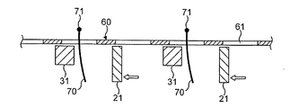
ここで図8a乃至図8iを参照し、現在理解されている剃刀装置の作動についてより詳細に説明する。毛剃りする皮膚(図示せず)に網刃60が接触すると、毛70は網刃の開口61を通じて延びて刃エレメント21,31を含む内刃組立体と係合する。図8における第1の内刃の刃21および第2の内刃の刃31は図1におけるそれらの状態に対応し、第1の刃エレメント21は第2の刃エレメント31から等間隔に配置されている。
2つの矢印によって示されるように、第1の刃エレメント21は最初にモータ(図示せず)によって第1の横方向(左側)へと動かされる。第2の刃エレメント31はモータによって少なくとも直接的には駆動されないので、第1の刃エレメント21が第1の横方向に動いている間における網刃に対する第2の刃エレメント31の位置は、第2の刃エレメント31の慣性によって変化しないままであると考えられる。しかしながら、動力学的な効果は、第2の刃エレメント31の以下においては考慮されない様々な相対動きを生じさせ得る。
The operation of the razor apparatus now understood will be described in more detail with reference to FIGS. When the
As indicated by the two arrows, the
図8bに示したように、第1の刃エレメント21は、毛70が第1および第2の内刃20、30の隣接する刃エレメント21、31同士の間に挟まれるように、毛70を掴んで第2の刃エレメント31に押しつける。
As shown in FIG. 8 b, the
第1の刃エレメント21が第1の横方向(左側)へとさらに動くと、隣接する刃表面同士の間に捉えられた毛70と共に第2の刃エレメント31が第1の刃エレメント21によって左側へと押動され、毛70が引っ張られる。その結果、毛70の毛根71は、図8cおよび図8dに示したようにその毛胞から外側および網刃60の開口の縁部へといくらか引っ張られる。なお、毛根71の本来の位置は想像線で示されている。
When the
図8dは、毛70が、第1および第2の刃エレメント21、31の隣接する表面同士の間に掴まえられている間に切断される状態を示している。毛70は、刃エレメントと網刃とが協動する結果としてせん断される。しかしながら毛70は、第1および第2の刃エレメントの隣接する表面同士の間に掴まえられていないときにも、単純に第1ないし第2の内刃20、30の単一の刃エレメントが毛70を押動する間にせん断され得る。
FIG. 8d shows the
図8eは、2つの矢印によって示されるように、第1の内刃20の往復運動によって、第1の横方向とは反対側の第2の横方向(右側)へと駆動されている第1の刃エレメント21を示している。このことにより、第2の刃エレメント31と第1の刃エレメント21との接触が失われるとともに、第2の内刃30の慣性の効果によって互いに間隔が開く。図8dに示したように毛70がちょうど切断されると、毛70の毛根71はその毛胞内の元々の位置へと引っ込み、残った切株状の毛が皮膚の表面下に動き、改良された密着性へと帰着する。
図8f乃至図8iにおいては、対応する図8a乃至図8eと鏡像関係にある以外は同じ順序の作動ステップが生じる。特に図8fは、第1の刃エレメント21が第2の横方向へとさらに動き、網刃60の開口61を通過した新しい毛70と接触する状態を示している。図8gにおいては、隣接する第1および第2の刃エレメント21、31間に毛が捉えられ、切断される前に引っ張られている。その後、上述したように、毛はは引っ張られている間に切断される。図8iに示されるように、第1の内刃20の往復運動によって第1の刃エレメント21は第1の方向へと動き直し、かつ毛70の毛根71は再びそれらの毛胞内に戻って元の状態となる。
In FIG. 8e, the first
In FIGS. 8f to 8i, the same sequence of operating steps occurs except that they are mirror images of the corresponding FIGS. 8a to 8e. In particular, FIG. 8 f shows the state in which the
次いで上述した順序が繰り返され、再び図8aの状態から開始する。しかしながら、言及されるべきことは、隣接する刃エレメント同士の間に毛が捉えられ、捉えられつつ切断される前に毛が毛胞から引っ張り出されることに関し、上述した模式的な説明図は1つの可能性であるということである。また、隣接する第1および第2の刃エレメントによって捉えられた毛が毛胞から引き離された後に毛を切断することもできるし、あるいは引っ張ることなしに通常の方法で毛を切断することもできる。この理由は、第2の刃エレメントが、駆動されている第1の刃エレメント同士の間で前後にはね返るからである。
あるいは、第2の内刃を、往復運動方向における第1の内刃に対する動きのために、第2の内刃の弾力的あるいは移動可能な支持、例えばハウジング内のボールベアリングによって取り付けることができる。さらに、第2の内刃は、第1の内刃の交互に配置されている刃エレメント間で自由に、すなわち、第1の内刃の内側で案内されるが第1の内刃に対してばねで付勢されることなしに動くこともできる。
The sequence described above is then repeated and starts again from the state of FIG. 8a. However, what should be mentioned is that the hair is caught between adjacent blade elements, and that the hair is pulled out of the follicle before being cut while being caught, the schematic illustration described above is 1 Is one possibility. The hair captured by the adjacent first and second blade elements can be cut after the hair has been pulled away from the follicle, or the hair can be cut in a normal manner without being pulled. . This is because the second blade element rebounds back and forth between the driven first blade elements.
Alternatively, the second inner blade can be mounted by a resilient or movable support of the second inner blade, for example a ball bearing in the housing, for movement relative to the first inner blade in the reciprocating direction. Furthermore, the second inner blade is guided freely between the alternately arranged blade elements of the first inner blade, i.e. inside the first inner blade but with respect to the first inner blade. It can also move without being biased by a spring.
上述した実施例によると第1および第2の内刃が金属から製造されるものと認識されるが、第2の内刃は代わりにプラスチック材料から製造することもできる。特に、むくの棒材から機械加工するとともに、その表面に円周溝を切り込んで刃エレメントを形成することにより製造することができる。プラスチック材料製の第2の内刃は、作動時において金属製のものよりも静かであるばかりでなく、掴み作用および耐摩耗性を改良すために、例えば炭化物である粒子を充填するという選択肢を提供する。第2の内刃の刃エレメントは、それらが金属製である場合であっても研ぐ必要はなく、それらは例えば比較的鈍くても良いし、高摩擦コーティングを有することもできるし、あるいは行程の一方向においてのみ毛を切断するように研磨することもできる。それらは、例えばプラスチックから製造され、仕上げがなめらかでなく、および/または良好な摩擦面を提供するためにエラストマを含有することもできる。 Although it is recognized that the first and second inner blades are made from metal according to the above-described embodiments, the second inner blade can alternatively be made from a plastic material. In particular, it can be manufactured by machining from a bar material and forming a blade element by cutting a circumferential groove on its surface. The second inner blade made of plastic material is not only quieter than that made of metal in operation, but also has the option of being filled with particles, for example carbides, in order to improve the gripping action and wear resistance. provide. The blade elements of the second inner blade do not need to be sharpened even if they are made of metal, they can be, for example, relatively dull, can have a high friction coating, or can be It is also possible to polish so as to cut the hair only in one direction. They are made, for example, from plastic and can also contain elastomers to provide a smooth surface and / or a good friction surface.
図10に模式的に示されている他の可能な実施例は、慣性の効果だけによってもたらされる効果を超えて掴み効果を高めるために、磁石101、102を使用している。そのような実施例においては、磁石101、102は内刃の端部に配設され、例えば第2の内刃がプラスチック製の内刃の両端部にある極性の極を有するとともに、第1の内刃がその両端に反対の極性の極を有し、それによって切り替え作用を達成するとともに右側ないし左側の掴み位置へと刃エレメントを付勢する。図6ないし図7に示されているタイプのばね構造と共に磁石を用い得ることは理解される。
Another possible embodiment, shown schematically in FIG. 10, uses
明らかなように、第1の内刃が普通の内刃である場合には、第2の内刃を追加することは実際上は刃の数を2倍にすることであり、多すぎる数の刃エレメントが網刃の下側で振動することによっておそらくは剃刀効率が低下することになる。したがって、第1の内刃と同じ数の刃を有した第2の内刃を用いるときには、内刃の刃の数が全体として普通の内刃と同じとなるように、第1の内刃は普通の内刃よりも少ない刃を有することが望ましい。 As can be seen, when the first inner blade is a normal inner blade, adding the second inner blade effectively doubles the number of blades, and there are too many The blade element will vibrate below the mesh blade, possibly reducing razor efficiency. Therefore, when the second inner blade having the same number of blades as the first inner blade is used, the first inner blade has the same number of inner blades as an ordinary inner blade as a whole. It is desirable to have fewer blades than ordinary inner blades.
第2の内刃は、第1の内刃の内側に入れ子にされているので、効果的な切断範囲において網刃と接するように、幅方向において4mm未満の寸法である。しかしながら、第2の内刃が普通の第1の内刃と同じ刃エレメントの分布を有している構成(例えば「Syncro」の名前で市販されているモデル6016ないし6017のように、0.12mmの厚さの27枚の刃エレメントが31mmの長さにわたって等間隔で配置されているもの)の場合には、次のことが観察された。すなわち、線形の往復運動の間に、第1の内刃の刃エレメントが、網刃のハニカム状に分布している(それぞれが幅方向において一般的に0.6mmの寸法を有した)開口のうち3つの開口のみを横切るのに対して、第2の内刃の各刃エレメントは5つの開口を横切るように動くことが観察された。したがって、第2の内刃は第1の内刃よりも66%多く動いて、刃エレメントと開口とのより多くの相互作用を生じさせ、特に0.6mmを超える移動距離に渡って2つの内刃の刃エレメントが毛を捉え、或いは挟む関係にあるときには毛を切断するイベントを生じさせる可能性を増加させる。 Since the second inner blade is nested inside the first inner blade, the second inner blade has a dimension of less than 4 mm in the width direction so as to contact the mesh blade in an effective cutting range. However, a configuration in which the second inner blade has the same distribution of blade elements as an ordinary first inner blade (e.g. 0.12 mm, such as models 6016 to 6017 marketed under the name "Syncro") The following was observed in the case of 27 blade elements having a thickness of 30 mm, which are arranged at equal intervals over a length of 31 mm. That is, during the linear reciprocating motion, the blade elements of the first inner blade are distributed in a mesh-like honeycomb shape (each having a size of generally 0.6 mm in the width direction). It was observed that each blade element of the second inner blade moved across five apertures, whereas only three of them were traversed. Therefore, the second inner blade moves 66% more than the first inner blade, resulting in more interaction between the blade element and the opening, especially the two inner blades over a travel distance of more than 0.6 mm. When the blade element of the blade is in a relationship of catching or pinching hair, it increases the possibility of causing an event of cutting the hair.
第2の内刃が追加の質量を動力学的システムに加えるので、剃刀装置の頭部および本体の振動の増加に帰着するから、それとは反対の作用をなすためにモータに釣合錘を取り付けることが有益であることが観察された。更なる修正を当業者は見出すであろう。全てのそのような変更は、請求項におけるそれらの概要とはかかわりなく、以下の請求項によってカバーされることが意図される。 Since the second inner blade adds additional mass to the dynamic system, it results in increased vibration of the head and body of the razor device, so that a counterweight is attached to the motor to do the opposite It was observed that it was beneficial. Further modifications will be found by those skilled in the art. All such modifications are intended to be covered by the following claims, regardless of their summary in the claims.
Claims (11)
前記内刃組立体が、
前記駆動機構によって往復運動するように構成されるとともに第1の刃エレメントを有している第1の内刃と、
前記第1の内刃に対して変位するように前記第1の内刃の内側に配設されるとともに、前記第1の刃エレメントと交互に配置される第2の刃エレメントを有した第2の内刃と、を有していることを特徴とする内刃組立体。 An inner blade assembly for a dry type razor comprising an outer blade and a motor drive mechanism,
The inner blade assembly is
A first inner blade configured to reciprocate by the drive mechanism and having a first blade element;
A second blade element disposed inside the first inner blade so as to be displaced with respect to the first inner blade, and having a second blade element alternately disposed with the first blade element; And an inner blade assembly.
かつ前記内刃組立体の外周が、交互に配置された第1および第2の刃エレメントの周縁によって形成されていることを特徴とする請求項1乃至4のいずれかに記載の内刃組立体。 The second inner blade is nested inside the first inner blade;
5. The inner blade assembly according to claim 1, wherein the outer periphery of the inner blade assembly is formed by the peripheral edges of the first and second blade elements arranged alternately. .
前記外刃に隣接する、請求項1乃至6のいずれかに記載の内刃組立体と、
前記内刃組立体を往復運動方向に交互に動かすためのモータ駆動機構と、
を備え、
前記内刃組立体の第1の内刃が、前記往復運動方向に駆動されるように前記モータ駆動機構に連結されており、
かつ前記第1の内刃の往復運動に応じて前記内刃組立体の第2の内刃が前記第1の内刃に対して往復運動するように、前記第2の内刃が前記往復運動方向において前記第1の内刃に対して動くように取り付けられていることを特徴とする剃刀装置。 An outer blade having a plurality of openings;
The inner blade assembly according to any one of claims 1 to 6, adjacent to the outer blade;
A motor drive mechanism for alternately moving the inner blade assembly in the reciprocating direction;
With
A first inner blade of the inner blade assembly is coupled to the motor drive mechanism so as to be driven in the reciprocating direction;
The second inner blade is reciprocated so that the second inner blade of the inner blade assembly reciprocates with respect to the first inner blade in response to the reciprocating motion of the first inner blade. A razor device mounted in a direction to move relative to the first inner blade.
かつ第2の内刃が第2の付勢要素によって前記外刃に向かって付勢されていることを特徴とする請求項7に記載の剃刀装置。 The first inner blade is biased toward the outer blade by a first biasing element;
The razor device according to claim 7, wherein the second inner blade is biased toward the outer blade by a second biasing element.
かつ前記第2の付勢要素の第2の端部が前記第2の内刃に接続されていることを特徴とする請求項8に記載の剃刀装置。 A first end of the second biasing element is connected to the first inner blade;
The razor device according to claim 8, wherein a second end portion of the second biasing element is connected to the second inner blade.
かつ前記第1および第2の付勢要素のそれぞれの第2の端部が前記第1および第2の内刃にそれぞれ接続されていることを特徴とする請求項8に記載の剃刀装置。 A first end of each of the first and second biasing elements is connected to a support;
The razor device according to claim 8, wherein the second ends of the first and second biasing elements are connected to the first and second inner blades, respectively.
前記第1および第2の内刃が交互に配置された刃エレメントを有しており、
外刃と共に毛をせん断する関係において前記内刃組立体を往復運動させる段階と、
この往復運動の一方向において前記第1の内刃を第2の内刃に対して移動させ、それによって移動する前記第1の内刃が前記第2の内刃を乗せて運ぶとともに、前記第1の内刃の継続的な動きが、当該一方向において前記第2の内刃が前記第1の内刃と共に動くことを強制する段階と、
第1の内刃の移動方向を反転させ、それによって第1の内刃の継続的な動きが前記第2の内刃が前記一方向とは反対方向となる他方向に動くようにさせる段階と、
前記外刃と前記内刃組立体との間で毛を切断する段階と、
を備えることを特徴とする方法。 A method of shaving using a razor device comprising an inner blade assembly having a first inner blade and a second inner blade,
The first and second inner blades have blade elements alternately disposed;
Reciprocating the inner blade assembly in a shearing relationship with the outer blade;
The first inner blade is moved relative to the second inner blade in one direction of the reciprocating motion, and the first inner blade moved thereby carries the second inner blade and carries the second inner blade. A continuous movement of one inner blade forcing the second inner blade to move with the first inner blade in the one direction ;
Reversing the direction of movement of the first inner blade so that the continuous movement of the first inner blade causes the second inner blade to move in a direction opposite to the one direction; ,
Cutting hair between the outer blade and the inner blade assembly;
A method comprising the steps of:
Applications Claiming Priority (1)
| Application Number | Priority Date | Filing Date | Title |
|---|---|---|---|
| EP20020020467 EP1398122B1 (en) | 2002-09-12 | 2002-09-12 | Undercutter for a shaving apparatus |
Publications (3)
| Publication Number | Publication Date |
|---|---|
| JP2004261578A JP2004261578A (en) | 2004-09-24 |
| JP2004261578A5 JP2004261578A5 (en) | 2006-10-26 |
| JP4467932B2 true JP4467932B2 (en) | 2010-05-26 |
Family
ID=31725410
Family Applications (1)
| Application Number | Title | Priority Date | Filing Date |
|---|---|---|---|
| JP2003321926A Expired - Lifetime JP4467932B2 (en) | 2002-09-12 | 2003-09-12 | Inner blade assembly, razor device, and method of shaving using razor device |
Country Status (8)
| Country | Link |
|---|---|
| US (3) | US6935027B2 (en) |
| EP (1) | EP1398122B1 (en) |
| JP (1) | JP4467932B2 (en) |
| CN (1) | CN100509313C (en) |
| AT (1) | ATE267670T1 (en) |
| DE (1) | DE60200553T2 (en) |
| ES (1) | ES2222425T3 (en) |
| RU (1) | RU2254980C2 (en) |
Families Citing this family (23)
| Publication number | Priority date | Publication date | Assignee | Title |
|---|---|---|---|---|
| US7504751B2 (en) * | 2002-09-11 | 2009-03-17 | Braun Gmbh | Small electric appliance with a drive mechanism for generating an oscillatory motion |
| CN1744972A (en) * | 2003-01-31 | 2006-03-08 | 皇家飞利浦电子股份有限公司 | Cutter unit for a shaver and shaver with a cutter |
| DE602005023610D1 (en) * | 2004-06-21 | 2010-10-28 | Koninkl Philips Electronics Nv | SHAVER |
| GB0416534D0 (en) * | 2004-07-23 | 2004-08-25 | Gillette Man Inc | A cutter assembly and method of producing same |
| JP4878750B2 (en) | 2004-11-25 | 2012-02-15 | 株式会社泉精器製作所 | Reciprocating electric razor |
| KR20070102699A (en) * | 2005-01-03 | 2007-10-19 | 코닌클리케 필립스 일렉트로닉스 엔.브이. | Hair-clipping device and cutter-member assembly for such a device |
| US20070022606A1 (en) * | 2005-07-29 | 2007-02-01 | Mcguire Kenneth S | Shaving foil |
| US7845079B2 (en) * | 2005-07-29 | 2010-12-07 | The Gillette Company | Shaving foil |
| WO2008002994A2 (en) * | 2006-06-27 | 2008-01-03 | Prolabel, Inc. | Tool system replaceable heads and offset handle |
| US8065774B2 (en) | 2006-10-26 | 2011-11-29 | Margco International, Llc | Paint brush with detachable head |
| US8261398B2 (en) * | 2006-10-26 | 2012-09-11 | Margco International, Llc | Paint brush with detachable head |
| JP4595968B2 (en) * | 2007-07-12 | 2010-12-08 | パナソニック電工株式会社 | Reciprocating electric razor inner blade |
| US20100313425A1 (en) * | 2009-06-11 | 2010-12-16 | Christopher Martin Hawes | Variable amplitude vibrating personal care device |
| DE102009031628A1 (en) * | 2009-07-03 | 2011-01-05 | Braun Gmbh | Undercutter for dry shaver |
| DE102009031627A1 (en) * | 2009-07-03 | 2011-01-05 | Braun Gmbh | Under knife assembly for dry shaver |
| JP4990996B2 (en) * | 2010-03-26 | 2012-08-01 | パナソニック株式会社 | Electric razor |
| JP5453188B2 (en) * | 2010-07-08 | 2014-03-26 | パナソニック株式会社 | Reciprocating electric razor |
| JP2012016495A (en) * | 2010-07-08 | 2012-01-26 | Panasonic Electric Works Co Ltd | Reciprocating electric shaver |
| US10093029B2 (en) | 2012-07-31 | 2018-10-09 | Koninklijke Philips N.V. | Hair clipping device |
| BR112015001896B1 (en) * | 2012-07-31 | 2020-09-29 | Koninklijke Philips N.V. | HAIR CUTTING DEVICE, AND CUTTING SET FOR USE ON A HAIR CUTTING DEVICE |
| JP6876506B2 (en) * | 2017-04-27 | 2021-05-26 | マクセルホールディングス株式会社 | Electric razor |
| EP3663057A1 (en) | 2018-12-05 | 2020-06-10 | Koninklijke Philips N.V. | Cutter assembly for a hair cutting appliance |
| US20230064384A1 (en) * | 2021-08-27 | 2023-03-02 | Wahl Clipper Corporation | Shaver |
Family Cites Families (27)
| Publication number | Priority date | Publication date | Assignee | Title |
|---|---|---|---|---|
| DE439916C (en) | 1927-01-22 | Fried Krupp Akt Ges | Coal dust firing intended especially for steam boilers | |
| FR782569A (en) * | 1933-12-11 | 1935-06-07 | Cutting head for hair cutting devices, in particular for dry shaving devices | |
| US2048999A (en) * | 1935-07-12 | 1936-07-28 | Dailey Thomas Leo | Meat holding device |
| US2223205A (en) * | 1936-12-05 | 1940-11-26 | American Safety Razor Corp | Dry shaver |
| US2201349A (en) * | 1937-03-20 | 1940-05-21 | Scruggs Loyd | Electric razor |
| US2223294A (en) * | 1937-08-09 | 1940-11-26 | Gillette Safety Razor Co | Shaving implement |
| US2342808A (en) * | 1942-09-02 | 1944-02-29 | Earl B Johnson | Shaving machine |
| US2364250A (en) * | 1944-02-18 | 1944-12-05 | Stokes Joseph Thomas | Eel knife |
| US2440061A (en) * | 1945-04-30 | 1948-04-20 | Herbert E Page | Power-driven dry shaver |
| US2590452A (en) * | 1947-07-26 | 1952-03-25 | Albin K Peterson | Mechanical razor |
| US3074449A (en) * | 1961-01-09 | 1963-01-22 | Mikulas William | Device for opening nuts |
| NL278656A (en) * | 1961-05-31 | |||
| US3201178A (en) * | 1963-08-21 | 1965-08-17 | Matsushita Electric Works Ltd | Electric dry shaver head having trimmer edge |
| US3191648A (en) * | 1964-03-05 | 1965-06-29 | Robert B Dustrude | Folding frame handsaw |
| US3319682A (en) * | 1964-09-14 | 1967-05-16 | Vera M L Hall | Sandwich holder |
| US3556507A (en) * | 1968-04-12 | 1971-01-19 | Frederick Bailey Haskell | Fish holding apparatus |
| GB1351155A (en) * | 1971-07-27 | 1974-04-24 | Gillette Co | Electric shavers |
| US4003130A (en) * | 1974-06-12 | 1977-01-18 | Rookus James E | Hair raising panel for electric shavers |
| US4139940A (en) * | 1976-12-13 | 1979-02-20 | The Gillette Company | Electric shaver |
| JPS54387A (en) | 1977-05-31 | 1979-01-05 | Hitachi Zosen Corp | Method of handling bulk freight |
| IL56623A (en) * | 1979-02-08 | 1981-09-13 | Yeda Res & Dev | Hair cutting apparatus |
| US5131147A (en) * | 1991-06-24 | 1992-07-21 | Plevyak Joseph B | Reciprocal cam-powered razor |
| JP3237868B2 (en) * | 1991-07-15 | 2001-12-10 | 松下電工株式会社 | Manufacturing method of inner blade of reciprocating electric razor |
| US5611145A (en) * | 1991-12-20 | 1997-03-18 | Wetzel; Matthias | Dry-shaving apparatus |
| DE19543095C1 (en) * | 1995-11-18 | 1997-06-05 | Braun Ag | Dry shaver |
| USD487002S1 (en) * | 2003-05-14 | 2004-02-24 | Alper Sarihan | Sandwich decruster |
| US7174599B2 (en) * | 2003-06-19 | 2007-02-13 | Stiles Ronnie J | Ergonomic shielding tool for processing a surface |
-
2002
- 2002-09-12 AT AT02020467T patent/ATE267670T1/en not_active IP Right Cessation
- 2002-09-12 ES ES02020467T patent/ES2222425T3/en not_active Expired - Lifetime
- 2002-09-12 EP EP20020020467 patent/EP1398122B1/en not_active Expired - Lifetime
- 2002-09-12 DE DE2002600553 patent/DE60200553T2/en not_active Expired - Lifetime
-
2003
- 2003-09-11 RU RU2003127458A patent/RU2254980C2/en not_active IP Right Cessation
- 2003-09-11 US US10/660,974 patent/US6935027B2/en not_active Expired - Fee Related
- 2003-09-12 CN CNB031588182A patent/CN100509313C/en not_active Expired - Fee Related
- 2003-09-12 JP JP2003321926A patent/JP4467932B2/en not_active Expired - Lifetime
-
2005
- 2005-06-02 US US11/145,071 patent/US7065877B2/en not_active Expired - Fee Related
- 2005-06-02 US US11/144,493 patent/US7111399B2/en not_active Expired - Fee Related
Also Published As
| Publication number | Publication date |
|---|---|
| CN1500600A (en) | 2004-06-02 |
| DE60200553D1 (en) | 2004-07-01 |
| EP1398122B1 (en) | 2004-05-26 |
| DE60200553T2 (en) | 2004-10-21 |
| RU2254980C2 (en) | 2005-06-27 |
| US20050217116A1 (en) | 2005-10-06 |
| US20040083865A1 (en) | 2004-05-06 |
| CN100509313C (en) | 2009-07-08 |
| ATE267670T1 (en) | 2004-06-15 |
| ES2222425T3 (en) | 2005-02-01 |
| JP2004261578A (en) | 2004-09-24 |
| US6935027B2 (en) | 2005-08-30 |
| RU2003127458A (en) | 2005-03-27 |
| EP1398122A1 (en) | 2004-03-17 |
| US20050223559A1 (en) | 2005-10-13 |
| US7065877B2 (en) | 2006-06-27 |
| US7111399B2 (en) | 2006-09-26 |
Similar Documents
| Publication | Publication Date | Title |
|---|---|---|
| JP4467932B2 (en) | Inner blade assembly, razor device, and method of shaving using razor device | |
| EP2227359B1 (en) | Shaving device comprising a pivotably arranged assembly of cutting elements | |
| EP2170566B1 (en) | Grooming tool assembly | |
| KR101774370B1 (en) | Razor | |
| EP1697094B1 (en) | Safety razors | |
| JP4790267B2 (en) | A shaving system that performs multiple shaving operations | |
| JP2017529165A (en) | Razor for shaving with one or more reciprocating blades | |
| US20080016695A1 (en) | Hair Cutting Apparatus | |
| US20070283565A1 (en) | Multi type head moving shaver | |
| KR20060122880A (en) | A shaving device with a pivotable shaving head carrying an actively driven cutting member | |
| JP2010532221A (en) | Grooming tools | |
| JP2009535143A (en) | Cutting device and hair cutting instrument | |
| JPH04220283A (en) | Blade set for electric hair clippers | |
| KR20040104548A (en) | Hair removing device | |
| JP2007512882A (en) | Electric hair cutter cutter head | |
| JP2019171048A (en) | Body hair removal device | |
| JP3180090B2 (en) | Hair removal device and hair removal method using the same | |
| CN220279710U (en) | Double-blade hair clipper | |
| CN209717783U (en) | A kind of bicyclic cambered surface razor net | |
| CN213499323U (en) | Hair clipper head | |
| JP2012192094A (en) | Electric razor | |
| JP3706977B2 (en) | Electric razor | |
| KR820001366B1 (en) | Blade assembly of hair cutter | |
| JPS5856625Y2 (en) | Scraping device | |
| JPS623103Y2 (en) |
Legal Events
| Date | Code | Title | Description |
|---|---|---|---|
| A521 | Request for written amendment filed |
Free format text: JAPANESE INTERMEDIATE CODE: A523 Effective date: 20060908 |
|
| A621 | Written request for application examination |
Free format text: JAPANESE INTERMEDIATE CODE: A621 Effective date: 20060908 |
|
| A131 | Notification of reasons for refusal |
Free format text: JAPANESE INTERMEDIATE CODE: A131 Effective date: 20090929 |
|
| A521 | Request for written amendment filed |
Free format text: JAPANESE INTERMEDIATE CODE: A523 Effective date: 20100104 |
|
| TRDD | Decision of grant or rejection written | ||
| A01 | Written decision to grant a patent or to grant a registration (utility model) |
Free format text: JAPANESE INTERMEDIATE CODE: A01 Effective date: 20100126 |
|
| A01 | Written decision to grant a patent or to grant a registration (utility model) |
Free format text: JAPANESE INTERMEDIATE CODE: A01 |
|
| A61 | First payment of annual fees (during grant procedure) |
Free format text: JAPANESE INTERMEDIATE CODE: A61 Effective date: 20100224 |
|
| R150 | Certificate of patent or registration of utility model |
Free format text: JAPANESE INTERMEDIATE CODE: R150 |
|
| FPAY | Renewal fee payment (event date is renewal date of database) |
Free format text: PAYMENT UNTIL: 20130305 Year of fee payment: 3 |