JP4467685B2 - Close-up lens - Google Patents
Close-up lens Download PDFInfo
- Publication number
- JP4467685B2 JP4467685B2 JP33109999A JP33109999A JP4467685B2 JP 4467685 B2 JP4467685 B2 JP 4467685B2 JP 33109999 A JP33109999 A JP 33109999A JP 33109999 A JP33109999 A JP 33109999A JP 4467685 B2 JP4467685 B2 JP 4467685B2
- Authority
- JP
- Japan
- Prior art keywords
- lens
- close
- convex
- object side
- convex surface
- Prior art date
- Legal status (The legal status is an assumption and is not a legal conclusion. Google has not performed a legal analysis and makes no representation as to the accuracy of the status listed.)
- Expired - Fee Related
Links
Images


Landscapes
- Lenses (AREA)
Description
【0001】
【発明の属する技術分野】
本発明は、テレビカメラ、ビデオカメラ、写真用カメラ等の光学機器に用いる撮影レンズの前方に着脱可能に取り付け、撮影可能な物体距離の短縮化を図った近接撮影時に用いる高い光学性能を有したクローズアップレンズに関するものである。
【0002】
【従来の技術】
撮影可能な被写体距離をより短くして近接被写体を撮影する方法として、撮影レンズに内蔵されているマクロ機構を用いる方法や、撮影レンズの前方にクローズアップレンズを着脱可能に取り付けて撮影する方法等がある。
【0003】
前者は撮影レンズの一部を動かすことにより、さらに至近側の被写体の撮影を可能とするものであるが、レンズの操作のみで近接撮影ができるという利便性はある。しかしながら、この方法は通常撮影に比べて光学性能が低下する傾向がある。そのため、光学性能を重視する場合は撮影レンズの前方にクローズアップレンズを取り付けて撮影を行うことが一般的となっている。
【0004】
この種のクローズアップレンズは極めて簡易な手段により撮影レンズの至近距離を短縮することができるという特長がある。
【0005】
一般にこの種のクローズアップレンズは簡易なレンズ構成でしかも撮影レンズに装着したときの至近距離が短く、又収差変動が少なく、良好な画像が得られることが要望されている。特にクローズアップレンズ単独で収差補正が良好になされていることが要望されている。
【0006】
本出願人は、例えば特開平7−318802号公報において、撮影レンズの前方に着脱可能に取り付けて至近物体距離の短縮化を図った高い光学性能を有したクローズアップレンズを提案している。
【0007】
【発明が解決しようとする課題】
一方最近のように、例えばハイビジョン放送に代表されるように、さらに質の高い画質が求められる分野においては、撮影レンズの光学性能の向上とともに、それに取り付けて用いるクローズアップレンズもさらに高い光学性能を有するものが求められている。このような要求を満たすには、クローズアップレンズ単体で十分な収差補正がされている必要がある。
【0008】
例えばクローズアップレンズを単一レンズより構成すれば、レンズ系は小型軽量となるが、収差補正、例えば色収差の補正が不十分となり、至近距離を短くすることが難しいという問題点が生じてくる。
【0009】
又、複数枚のレンズより構成すれば至近距離を短くし、且つ収差補正を良好に行うことができるが、レンズ系全体が大型化してくるという問題点が生じてくる。
【0010】
本発明は、レンズ形状やレンズの材質、そして各レンズの屈折力等のレンズ構成上の諸元を適切に設定することにより撮影レンズの前方(物体側)に着脱可能に装着して至近距離を短くし、且つ画面全体の光学性能を良好に維持することができるクローズアップレンズの提供を目的とする。
【0011】
特に本発明は、主として放送用のテレビカメラ用のズームレンズの物体側に着脱可能に装着したときに光学性能の劣化が少なく、良好に使用できるクローズアップレンズの提供を目的とする。
【0012】
【課題を解決するための手段】
請求項1の発明のクローズアップレンズは、撮影レンズの前方に着脱可能に取り付けて使用するクローズアップレンズにおいて、該クローズアップレンズは、物体側から順に正のパワーを持つ第1レンズと、負のパワーを持つ第2レンズと、正のパワーを持つ第3レンズにて構成され、全系の焦点距離をfo、第iレンズの焦点距離をfi、第i番目のレンズ面の曲率半径をRi、第iレンズの材質のd線を基準としたときのアッベ数をνiとしたとき、
0.1<(R1+R2)/(R1−R2)< 2.4 ‥‥‥(1)
−4.4<(R3+R4)/(R3−R4)<−0.5 ‥‥‥(2)
−2.8<(R5+R6)/(R5−R6)< 0.9 ‥‥‥(3)
0.6<|f1/fo|<1.6 ‥‥‥(4)
0.4<|f2/fo|<1.2 ‥‥‥(5)
0.5<|f3/fo|<1.3 ‥‥‥(6)
|ν1−ν2|>10 ‥‥‥(7)
の条件を満足することを特徴としている。
【0013】
【発明の実施の形態】
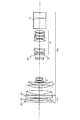
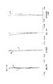
図1〜図3は本発明の実施形態の数値実施例1のクローズアップレンズCUを撮影レンズMLの前方に着脱可能に装着したときのレンズ断面図、広角端の収差図、望遠端の収差図である。
【0014】
図4〜図6は本発明の実施形態の数値実施例2のクローズアップレンズCUを撮影レンズMLの前方に着脱可能に装着したときのレンズ断面図、広角端の収差図、望遠端の収差図である。
【0015】
図7〜図9は本発明の実施形態の数値実施例3のクローズアップレンズCUを撮影レンズMLの前方に着脱可能に装着したときのレンズ断面図、広角端の収差図、望遠端の収差図である。
【0016】
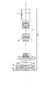
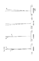
図10〜図12は本発明の実施形態の数値実施例4のクローズアップレンズCUを撮影レンズMLの前方に着脱可能に装着したときのレンズ断面図、広角端の収差図、望遠端の収差図である。
【0017】
レンズ断面図においてCUはクローズアップレンズである。MLは撮影レンズであり、ズームレンズより成っている。尚、本実施形態では撮影レンズMLにズームレンズを用いた場合を示しているが単一焦点距離のレンズ系であっても良い。
【0018】
クローズアップレンズCUは物体側より順に正のパワー(屈折力)の第1レンズG1、負のパワーの第2レンズG2、そして正のパワーの第3レンズG3より成っている。
【0019】
又、ズームレンズMLは物体側より順に変倍の際に固定のフォーカス用の正の屈折力の第1群(フォーカス部)、変倍用の負の屈折力の第2群(バリエータ)、変倍に伴う像面変動を補正する負の屈折力の第3群(コンペンセーター)、そして固定の正の屈折力の第4群(リレーレンズ)より成っている。
【0020】
SPは絞りである。Bは色分解プリズムや光学フィルターであり、同図ではガラスブロックとして示している。
【0021】
一般に撮影レンズはそれ自身で撮影を行うため、収差補正が良好になされている。そのため、クローズアップレンズを撮影レンズに装着したときに高い光学性能を得るためには、クローズアップレンズ単独で十分な収差補正を行っておく必要がある。
【0022】
本発明のクローズアップレンズCUは、物体側から順に正のパワーを持つ第1レンズG1と、負のパワーを持つ第2レンズG2と、正のパワーを持つ第3レンズG3にて構成すると共に、前述の条件式(1)〜(7)を満たすことで撮影可能な至近距離を短くしつつ、ズームレンズに装着した場合に重要となる広角端のディストーション(歪曲収差)及び望遠端の球面収差を良好に補正している。
【0023】
条件式(1)〜(3)は、クローズアップレンズCUを構成する第1レンズG1、第2レンズG2、第3レンズG3のレンズ形状を規定するもので、各構成レンズの形状がそれぞれに当てはまる条件式を満足することにより諸収差、特にズームレンズに装着したときの広角端のディストーション及び望遠端の球面収差を良好に補正している。
【0024】
第1レンズG1が条件式(1)の下限値を越えると、物体側のレンズ面が極端に強いパワーを持つ両レンズ面が凸面のレンズとなり、望遠端の球面収差の補正が困難になる。また、上限値を越えると、物体側に凹面を向けた極端なメニスカス形状となり、広角端の負のディストーションが増大するので良くない。
【0025】
第2レンズG2が条件式(2)の下限値を越えると、物体側に凹面を向けた極端なメニスカス形状のレンズとなり、望遠端の球面収差の補正が過剰となる。又、上限値を越えると像面側のレンズ面にパワーの強い凹面を持つ両レンズ面が凹面の負レンズとなり、広角端の負のディストーションが増大する。
【0026】
第3レンズG3が条件式▲3▼の下限値を越えると、物体側に凸面を向けた極端なメニスカス形状となり、望遠端の球面収差の補正が困難になる。又上限値を越えると、像面側のレンズ面が極端に強い両レンズ面が凸面の正レンズとなり、広角端のディストーションが過剰に補正されることに加え、望遠端の球面収差の補正も困難になる。
【0027】
条件式(4)〜(6)は、各構成レンズの焦点距離をクローズアップレンズ(全系)の焦点距離foで正規化し、その絶対値を規定したもので、条件式(4)〜(6)の下限値を越えると各構成レンズが強いパワーの組み合わせとなり、諸収差の補正が難しくなる。
【0028】
また上限を越えると各構成レンズが弱いパワーの組み合わせとなり、焦点距離foのクローズアップレンズを構成することが難しくなる。
【0029】
条件式(7)は、第1レンズG1と第2レンズG2の材質のd線を基準にしたアッベ数に関するもので、下限値を越えると色収差の十分な補正ができなくなる。
【0030】
本発明のクローズアップレンズCUの具体的なレンズ形状としては、物体側より順に、図1の数値実施例1で両レンズ面が凸面の正レンズ、像面に凸面を向けたメニスカス状の負レンズ、物体側に凸面を向けたメニスカス状の正レンズより構成している。
【0031】
又、図4の数値実施例2では像面側に凸面を向けたメニスカス状の正レンズ、像面側に凸面を向けたメニスカス状の負レンズ、両レンズ面が凸面の正レンズより構成している。
【0032】
又、図7の数値実施例3では両レンズ面が凸面の正レンズ、両レンズ面が凹面の負レンズ、両レンズ面が凸面の正レンズより構成している。
【0033】
又、図10の数値実施例4では両レンズ面が凸面の正レンズ、像面側に凸面を向けたメニスカス状の負レンズ、両レンズ面が凸面の正レンズより構成している。
【0034】
本発明のクローズアップレンズはこのようなレンズ形状をとることによって、クローズアップレンズ単体としての諸収差を良好に補正している。
【0035】
次に本発明のクローズアップレンズと、それを装着する撮影レンズの数値実施例を示す。撮影レンズは変倍比20倍、広角端のFナンバーが1.85、望遠端のFナンバーが2.85、広角端の画角60.1度のズームレンズである。
【0036】
数値実施例においてriは物体側から順に第i番目の面の曲率半径、diは物体側から順に第i番目と第(i+1)番目の間隔、niとνiはそれぞれ物体側より順に第i番目の光学部材の材質の屈折率とアッベ数である。
【0037】
尚撮影レンズの数値実施例において最終の3つのレンズ面は色分解プリズムやフィルター等のガラスブロックである。又前述の条件式と数値実施例における諸数値との関係を表−1に示す。
【0038】

【表1】
【発明の効果】
本発明によれば以上のように、レンズ形状やレンズの材質、そして各レンズの屈折力等のレンズ構成上の諸元を適切に設定することにより撮影レンズの前方(物体側)に着脱可能に装着して至近距離を短くし、且つ画面全体の光学性能を良好に維持することができるクローズアップレンズを達成することができる。
【0041】
この他本発明は、放送用のテレビカメラ用のズームレンズの物体側に着脱可能に装着したときに光学性能の劣化が少なく、良好に使用できるクローズアップレンズを達成することができる。
【図面の簡単な説明】
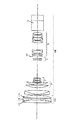
【図1】 本発明の数値実施例1のクローズアップレンズを撮影レンズに装着したときのレンズ断面図
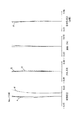
【図2】 本発明の数値実施例1のクローズアップレンズを撮影レンズに装着したときの広角端の収差図
【図3】 本発明の数値実施例1のクローズアップレンズを撮影レンズに装着したときの望遠端の収差図
【図4】 本発明の数値実施例2のクローズアップレンズを撮影レンズに装着したときのレンズ断面図
【図5】 本発明の数値実施例2のクローズアップレンズを撮影レンズに装着したときの広角端の収差図
【図6】 本発明の数値実施例2のクローズアップレンズを撮影レンズに装着したときの望遠端の収差図
【図7】 本発明の数値実施例3のクローズアップレンズを撮影レンズに装着したときのレンズ断面図
【図8】 本発明の数値実施例3のクローズアップレンズを撮影レンズに装着したときの広角端の収差図
【図9】 本発明の数値実施例3のクローズアップレンズを撮影レンズに装着したときの望遠端の収差図
【図10】 本発明の数値実施例4のクローズアップレンズを撮影レンズに装着したときのレンズ断面図
【図11】 本発明の数値実施例4のクローズアップレンズを撮影レンズに装着したときの広角端の収差図
【図12】 本発明の数値実施例4のクローズアップレンズを撮影レンズに装着したときの望遠端の収差図
【符号の説明】
CU:クローズアップレンズ
G1:第1レンズ
G2:第2レンズ
G3:第3レンズ
ML:撮影レンズ
F:フォーカス部
V:バリエータ
C:コンペンセーター
R:リレーレンズ
SP:絞り
g:g線
e:e線
S:サジタル像面
M:メリディオナル像面[0001]
BACKGROUND OF THE INVENTION
The present invention has a high optical performance used in close-up photography, which is detachably attached to the front of a taking lens used in an optical apparatus such as a TV camera, a video camera, a photographic camera, etc., and shortens the object distance that can be taken. It relates to a close-up lens.
[0002]
[Prior art]
As a method to shoot a close subject by shortening the shootable subject distance, a method using a macro mechanism built into the photographic lens, a method of detachably attaching a close-up lens in front of the photographic lens, etc. There is.
[0003]
The former makes it possible to shoot a subject on the closer side by moving a part of the photographic lens, but it has the convenience that close-up shooting can be performed only by operating the lens. However, this method has a tendency that the optical performance is lowered as compared with the normal photographing. For this reason, when importance is attached to optical performance, it is common to shoot with a close-up lens attached in front of the taking lens.
[0004]
This type of close-up lens has a feature that the close distance of the photographing lens can be shortened by a very simple means.
[0005]
In general, this type of close-up lens is required to have a simple lens configuration, a short distance when mounted on a photographing lens, and a small aberration variation so that a good image can be obtained. In particular, it is desired that aberration correction is satisfactorily performed with a close-up lens alone.
[0006]
For example, in Japanese Patent Application Laid-Open No. 7-318802, the present applicant has proposed a close-up lens having high optical performance that is detachably attached to the front of the photographing lens to shorten the object distance.
[0007]
[Problems to be solved by the invention]
On the other hand, as in recent years, for example, in the field where higher quality image quality is required, as represented by high-definition broadcasts, the optical performance of the taking lens is improved, and the close-up lens attached to it also has higher optical performance. What you have is in demand. In order to satisfy such a requirement, it is necessary that the close-up lens is sufficiently corrected for aberrations.
[0008]
For example, if the close-up lens is composed of a single lens, the lens system becomes small and light, but aberration correction, for example, correction of chromatic aberration becomes insufficient, and it is difficult to shorten the close distance.
[0009]
Further, if the lens is composed of a plurality of lenses, the close distance can be shortened and aberration correction can be performed satisfactorily, but there arises a problem that the entire lens system becomes large.
[0010]
In the present invention, by appropriately setting the lens configuration such as the lens shape, the lens material, and the refractive power of each lens, the lens can be detachably attached to the front (object side) of the photographing lens to reduce the close distance. An object of the present invention is to provide a close-up lens that can be shortened and can maintain good optical performance of the entire screen.
[0011]
In particular, it is an object of the present invention to provide a close-up lens that can be used satisfactorily with little deterioration in optical performance when it is detachably mounted on the object side of a zoom lens for a television camera for broadcasting.
[0012]
[Means for Solving the Problems]
The close-up lens according to the first aspect of the present invention is a close-up lens that is detachably attached to the front of the photographing lens. The close-up lens includes a first lens having positive power in order from the object side, and a negative lens. It is composed of a second lens having power and a third lens having positive power. The focal length of the entire system is fo, the focal length of the i-th lens is fi, the radius of curvature of the i-th lens surface is Ri, When the Abbe number when the d-line of the material of the i-th lens is used as a reference is νi,
0.1 <(R1 + R2) / (R1-R2) <2.4 (1)
−4.4 <(R3 + R4) / (R3−R4) <− 0.5 (2)
-2.8 <(R5 + R6) / (R5-R6) <0.9 (3)
0.6 <| f1 / fo | <1.6 (4)
0.4 <| f2 / fo | <1.2 (5)
0.5 <| f3 / fo | <1.3 (6)
| Ν1-ν2 |> 10 (7)
It is characterized by satisfying the following conditions.
[0013]
DETAILED DESCRIPTION OF THE INVENTION
FIGS. 1 to 3 are lens cross-sectional views, aberration diagrams at the wide-angle end, and aberration diagrams at the telephoto end when the close-up lens CU according to Numerical Example 1 of the embodiment of the present invention is detachably mounted in front of the photographing lens ML. It is.
[0014]
4 to 6 are lens cross-sectional views, wide-angle end aberration diagrams, and telephoto end aberration diagrams when the close-up lens CU according to Numerical Example 2 of the embodiment of the present invention is detachably mounted in front of the photographing lens ML. It is.
[0015]
7 to 9 are lens cross-sectional views, aberration diagrams at the wide-angle end, and aberration diagrams at the telephoto end when the close-up lens CU according to Numerical Example 3 of the embodiment of the present invention is detachably mounted in front of the photographing lens ML. It is.
[0016]
10 to 12 are lens cross-sectional views, aberration diagrams at the wide-angle end, and aberration diagrams at the telephoto end when the close-up lens CU according to Numerical Example 4 of the embodiment of the present invention is detachably mounted in front of the photographing lens ML. It is.
[0017]
In the lens cross-sectional view, CU is a close-up lens. ML is a photographic lens and is composed of a zoom lens. In the present embodiment, a zoom lens is used as the photographing lens ML, but a lens system having a single focal length may be used.
[0018]
The close-up lens CU includes, in order from the object side, a first lens G1 having a positive power (refractive power), a second lens G2 having a negative power, and a third lens G3 having a positive power.
[0019]
In addition, the zoom lens ML is arranged in order from the object side during zooming, a first group of positive refractive power for fixed focus (focus portion), a second group of negative refractive power for zooming (variator), and zooming. It consists of a third group (compensator) with a negative refractive power that corrects image plane fluctuations accompanying magnification, and a fourth group (relay lens) with a fixed positive refractive power.
[0020]
SP is an aperture. B is a color separation prism or an optical filter, and is shown as a glass block in FIG.
[0021]
In general, since a photographic lens shoots itself, aberration correction is excellent. Therefore, in order to obtain high optical performance when the close-up lens is attached to the photographing lens, it is necessary to perform sufficient aberration correction with the close-up lens alone.
[0022]
The close-up lens CU according to the present invention includes a first lens G1 having a positive power in order from the object side, a second lens G2 having a negative power, and a third lens G3 having a positive power. By satisfying the above-mentioned conditional expressions (1) to (7), it is possible to reduce the wide-angle end distortion (distortion aberration) and the telephoto end spherical aberration, which are important when the zoom lens is mounted while shortening the closest distance that can be photographed. Corrected well.
[0023]
Conditional expressions (1) to (3) define the lens shapes of the first lens G1, the second lens G2, and the third lens G3 that constitute the close-up lens CU, and the shapes of the constituent lenses apply to the respective lenses. By satisfying the conditional expression, various aberrations, in particular, distortion at the wide-angle end and spherical aberration at the telephoto end when the zoom lens is mounted are satisfactorily corrected.
[0024]
When the first lens G1 exceeds the lower limit value of the conditional expression (1), both lens surfaces having extremely strong power on the object side lens surface become convex lenses, making it difficult to correct spherical aberration at the telephoto end. On the other hand, if the upper limit is exceeded, an extreme meniscus shape with the concave surface facing the object side is formed, and negative distortion at the wide-angle end increases, which is not good.
[0025]
When the second lens G2 exceeds the lower limit value of the conditional expression (2), the lens becomes an extreme meniscus lens having a concave surface directed toward the object side, and correction of spherical aberration at the telephoto end becomes excessive. If the upper limit is exceeded, both lens surfaces having a strong concave surface on the image surface side become negative negative lenses, and negative distortion at the wide-angle end increases.
[0026]
When the third lens G3 exceeds the lower limit value of the conditional expression (3), it becomes an extreme meniscus shape with the convex surface facing the object side, making it difficult to correct spherical aberration at the telephoto end. If the upper limit is exceeded, both lens surfaces that are extremely strong on the image surface side become convex positive lenses, and distortion at the wide-angle end is excessively corrected, and spherical aberration at the telephoto end is also difficult to correct. become.
[0027]
Conditional expressions (4) to (6) are obtained by normalizing the focal length of each component lens with the focal length fo of the close-up lens (entire system) and defining the absolute value thereof. Conditional expressions (4) to (6) If the lower limit value is exceeded, each component lens has a combination of strong powers, making it difficult to correct various aberrations.
[0028]
If the upper limit is exceeded, each component lens has a combination of weak power, making it difficult to construct a close-up lens with a focal length fo.
[0029]
Conditional expression (7) relates to the Abbe number based on the d-line of the material of the first lens G1 and the second lens G2. If the lower limit is exceeded, chromatic aberration cannot be corrected sufficiently.
[0030]
As a specific lens shape of the close-up lens CU of the present invention, in order from the object side, in the numerical example 1 of FIG. 1, both lens surfaces are convex positive lenses, and meniscus negative lenses with convex surfaces facing the image surface And a meniscus positive lens having a convex surface facing the object side.
[0031]
In Numerical Example 2 in FIG. 4, a meniscus positive lens having a convex surface facing the image surface, a meniscus negative lens having a convex surface facing the image surface, and a positive lens having both lens surfaces convex. Yes.
[0032]
Further, in Numerical Example 3 of FIG. 7, both lens surfaces are composed of convex positive lenses, both lens surfaces are composed of concave negative lenses, and both lens surfaces are composed of convex positive lenses.
[0033]
Further, in Numerical Example 4 of FIG. 10, both lens surfaces are composed of a convex positive lens, a meniscus negative lens having a convex surface facing the image surface side, and both lens surfaces are composed of a convex positive lens.
[0034]
The close-up lens of the present invention has such a lens shape, and thereby corrects various aberrations as a single close-up lens.
[0035]
Next, numerical examples of the close-up lens of the present invention and a photographing lens to which the close-up lens is attached will be shown. The photographic lens is a zoom lens with a zoom ratio of 20 times, an F number at the wide angle end of 1.85, an F number at the telephoto end of 2.85, and an angle of view of 60.1 degrees at the wide angle end.
[0036]
In the numerical example, ri is the radius of curvature of the i-th surface in order from the object side, di is the i-th and (i + 1) th intervals in order from the object side, and ni and νi are the i-th in order from the object side. The refractive index and Abbe number of the material of the optical member.
[0037]
In the numerical example of the photographing lens, the last three lens surfaces are glass blocks such as a color separation prism and a filter. Table 1 shows the relationship between the above-described conditional expressions and various numerical values in the numerical examples.
[0038]
[Table 1]
【The invention's effect】
As described above, according to the present invention, the lens configuration, the lens material, and the lens configuration such as the refractive power of each lens are appropriately set so that the lens can be attached to the front (object side) of the photographing lens. It is possible to achieve a close-up lens that can be attached to shorten the close distance and maintain good optical performance of the entire screen.
[0041]
In addition, the present invention can achieve a close-up lens that can be used satisfactorily with little deterioration in optical performance when it is detachably mounted on the object side of a zoom lens for a broadcast television camera.
[Brief description of the drawings]
FIG. 1 is a cross-sectional view of a lens when the close-up lens of Numerical Example 1 of the present invention is attached to a photographic lens. FIG. 2 is a wide angle when the close-up lens of Numerical Example 1 of the present invention is attached to a photographic lens. FIG. 3 shows aberrations at the telephoto end when the close-up lens according to Numerical Example 1 of the present invention is attached to the photographing lens. FIG. 4 shows the close-up lens according to Numerical Example 2 according to the present invention as the photographing lens. FIG. 5 is a cross-sectional view of the lens when mounted on the lens. FIG. 5 is an aberration diagram at the wide-angle end when the close-up lens of Numerical Example 2 of the present invention is mounted on a photographing lens. Aberration diagram at the telephoto end when the lens is attached to the photographing lens. FIG. 7 is a sectional view of the lens when the close-up lens of Numerical Example 3 of the present invention is attached to the photographing lens. FIG. 9 is an aberration diagram at the wide-angle end when the close-up lens of Example 3 is attached to the photographing lens. FIG. 9 is an aberration diagram at the telephoto end when the close-up lens of Numerical Example 3 of the present invention is attached to the photographing lens. FIG. 11 is a lens cross-sectional view when the close-up lens of Numerical Example 4 of the present invention is attached to a photographing lens. FIG. 11 shows aberrations at the wide-angle end when the close-up lens of Numerical Example 4 of the present invention is attached to a photographing lens. FIG. 12 is an aberration diagram at the telephoto end when the close-up lens according to Numerical Example 4 of the present invention is attached to the photographing lens.
CU: Close-up lens G1: First lens G2: Second lens G3: Third lens ML: Shooting lens F: Focus unit V: Variator C: Compensator R: Relay lens SP: Aperture g: g line e: e line S: Sagittal image plane M: Meridional image plane
Claims (8)
該クローズアップレンズは、物体側から順に正のパワーを持つ第1レンズと、負のパワーを持つ第2レンズと、正のパワーを持つ第3レンズにて構成され、全系の焦点距離をfo、第iレンズの焦点距離をfi、第i番目のレンズ面の曲率半径をRi、第iレンズの材質のd線を基準としたときのアッベ数をνiとしたとき、
0.1<(R1+R2)/(R1−R2)< 2.4
−4.4<(R3+R4)/(R3−R4)<−0.5
−2.8<(R5+R6)/(R5−R6)< 0.9
0.6<|f1/fo|<1.6
0.4<|f2/fo|<1.2
0.5<|f3/fo|<1.3
|ν1−ν2|>10
の条件を満足することを特徴とするクローズアップレンズ。In the close-up lens to be used detachably attached to the front of the taking lens,
The close-up lens is composed of a first lens having a positive power in order from the object side, a second lens having a negative power, and a third lens having a positive power. When the focal length of the i-th lens is fi, the radius of curvature of the i-th lens surface is Ri, and the Abbe number with respect to the d-line of the material of the i-th lens is νi,
0.1 <(R1 + R2) / (R1-R2) <2.4
−4.4 <(R3 + R4) / (R3−R4) <− 0.5
-2.8 <(R5 + R6) / (R5-R6) <0.9
0.6 <| f1 / fo | <1.6
0.4 <| f2 / fo | <1.2
0.5 <| f3 / fo | <1.3
| Ν1-ν2 |> 10
A close-up lens that satisfies the above conditions.
Priority Applications (1)
| Application Number | Priority Date | Filing Date | Title |
|---|---|---|---|
| JP33109999A JP4467685B2 (en) | 1999-11-22 | 1999-11-22 | Close-up lens |
Applications Claiming Priority (1)
| Application Number | Priority Date | Filing Date | Title |
|---|---|---|---|
| JP33109999A JP4467685B2 (en) | 1999-11-22 | 1999-11-22 | Close-up lens |
Publications (3)
| Publication Number | Publication Date |
|---|---|
| JP2001147369A JP2001147369A (en) | 2001-05-29 |
| JP2001147369A5 JP2001147369A5 (en) | 2007-01-11 |
| JP4467685B2 true JP4467685B2 (en) | 2010-05-26 |
Family
ID=18239857
Family Applications (1)
| Application Number | Title | Priority Date | Filing Date |
|---|---|---|---|
| JP33109999A Expired - Fee Related JP4467685B2 (en) | 1999-11-22 | 1999-11-22 | Close-up lens |
Country Status (1)
| Country | Link |
|---|---|
| JP (1) | JP4467685B2 (en) |
Families Citing this family (2)
| Publication number | Priority date | Publication date | Assignee | Title |
|---|---|---|---|---|
| JP2005172938A (en) * | 2003-12-08 | 2005-06-30 | Fujinon Corp | Vibration isolating zoom lens |
| JP4579568B2 (en) * | 2004-04-01 | 2010-11-10 | キヤノン株式会社 | Zoom lens and shooting system |
-
1999
- 1999-11-22 JP JP33109999A patent/JP4467685B2/en not_active Expired - Fee Related
Also Published As
| Publication number | Publication date |
|---|---|
| JP2001147369A (en) | 2001-05-29 |
Similar Documents
| Publication | Publication Date | Title |
|---|---|---|
| JP3584107B2 (en) | Zoom lens | |
| JP4507140B2 (en) | 3 group zoom lens | |
| JP3606548B2 (en) | 3 group zoom lens | |
| KR101612444B1 (en) | Macro lens system and pickup device having the same | |
| JP4510178B2 (en) | Zoom lens | |
| JP3445095B2 (en) | Zoom lens and camera having the same | |
| KR100484718B1 (en) | Zoom lens and camera with the zoom lens | |
| JPH10293253A (en) | Three-group zoom lens | |
| JPH1062686A (en) | Inner focusing type zoom lens | |
| JPH05173070A (en) | Zoom lens | |
| JP4235288B2 (en) | Rear focus zoom lens | |
| JP4343307B2 (en) | Rear focus zoom lens | |
| JP4847091B2 (en) | Zoom lens and imaging apparatus having the same | |
| JPH09179004A (en) | Photographic lens optical system | |
| US7679836B2 (en) | Zoom lens system and image pickup apparatus equipped with the same | |
| US7342730B2 (en) | Zoom lens optical system | |
| JP3548537B2 (en) | Zoom lens and optical device using the same | |
| US4491395A (en) | Zoom lens system | |
| JP3619153B2 (en) | Zoom lens and optical apparatus using the same | |
| JP2761920B2 (en) | Small wide-angle zoom lens | |
| JP2840283B2 (en) | Shooting lens system | |
| JP4321729B2 (en) | Zoom lens | |
| JP2004037700A (en) | Zoom lens and optical device having same | |
| JP4467685B2 (en) | Close-up lens | |
| JP4011786B2 (en) | Rear focus zoom lens |
Legal Events
| Date | Code | Title | Description |
|---|---|---|---|
| A521 | Written amendment |
Free format text: JAPANESE INTERMEDIATE CODE: A523 Effective date: 20061114 |
|
| A621 | Written request for application examination |
Free format text: JAPANESE INTERMEDIATE CODE: A621 Effective date: 20061114 |
|
| A977 | Report on retrieval |
Free format text: JAPANESE INTERMEDIATE CODE: A971007 Effective date: 20100212 |
|
| TRDD | Decision of grant or rejection written | ||
| A01 | Written decision to grant a patent or to grant a registration (utility model) |
Free format text: JAPANESE INTERMEDIATE CODE: A01 Effective date: 20100223 |
|
| A01 | Written decision to grant a patent or to grant a registration (utility model) |
Free format text: JAPANESE INTERMEDIATE CODE: A01 |
|
| A61 | First payment of annual fees (during grant procedure) |
Free format text: JAPANESE INTERMEDIATE CODE: A61 Effective date: 20100224 |
|
| R150 | Certificate of patent or registration of utility model |
Free format text: JAPANESE INTERMEDIATE CODE: R150 |
|
| FPAY | Renewal fee payment (event date is renewal date of database) |
Free format text: PAYMENT UNTIL: 20130305 Year of fee payment: 3 |
|
| FPAY | Renewal fee payment (event date is renewal date of database) |
Free format text: PAYMENT UNTIL: 20140305 Year of fee payment: 4 |
|
| LAPS | Cancellation because of no payment of annual fees |