JP4464963B2 - Location privacy for Internet protocol networks using cryptographically protected prefixes - Google Patents
Location privacy for Internet protocol networks using cryptographically protected prefixes Download PDFInfo
- Publication number
- JP4464963B2 JP4464963B2 JP2006517182A JP2006517182A JP4464963B2 JP 4464963 B2 JP4464963 B2 JP 4464963B2 JP 2006517182 A JP2006517182 A JP 2006517182A JP 2006517182 A JP2006517182 A JP 2006517182A JP 4464963 B2 JP4464963 B2 JP 4464963B2
- Authority
- JP
- Japan
- Prior art keywords
- router
- address
- routers
- key
- prefix
- Prior art date
- Legal status (The legal status is an assumption and is not a legal conclusion. Google has not performed a legal analysis and makes no representation as to the accuracy of the status listed.)
- Expired - Fee Related
Links
Images


Classifications
-
- H—ELECTRICITY
- H04—ELECTRIC COMMUNICATION TECHNIQUE
- H04L—TRANSMISSION OF DIGITAL INFORMATION, e.g. TELEGRAPHIC COMMUNICATION
- H04L63/00—Network architectures or network communication protocols for network security
- H04L63/04—Network architectures or network communication protocols for network security for providing a confidential data exchange among entities communicating through data packet networks
- H04L63/0428—Network architectures or network communication protocols for network security for providing a confidential data exchange among entities communicating through data packet networks wherein the data content is protected, e.g. by encrypting or encapsulating the payload
-
- H—ELECTRICITY
- H04—ELECTRIC COMMUNICATION TECHNIQUE
- H04L—TRANSMISSION OF DIGITAL INFORMATION, e.g. TELEGRAPHIC COMMUNICATION
- H04L61/00—Network arrangements, protocols or services for addressing or naming
-
- H—ELECTRICITY
- H04—ELECTRIC COMMUNICATION TECHNIQUE
- H04L—TRANSMISSION OF DIGITAL INFORMATION, e.g. TELEGRAPHIC COMMUNICATION
- H04L63/00—Network architectures or network communication protocols for network security
- H04L63/08—Network architectures or network communication protocols for network security for authentication of entities
- H04L63/0853—Network architectures or network communication protocols for network security for authentication of entities using an additional device, e.g. smartcard, SIM or a different communication terminal
-
- H—ELECTRICITY
- H04—ELECTRIC COMMUNICATION TECHNIQUE
- H04L—TRANSMISSION OF DIGITAL INFORMATION, e.g. TELEGRAPHIC COMMUNICATION
- H04L63/00—Network architectures or network communication protocols for network security
- H04L63/16—Implementing security features at a particular protocol layer
- H04L63/166—Implementing security features at a particular protocol layer at the transport layer
Description
(関連出願の相互参照)
本出願は、(2003年6月24日に出願された)仮出願第60/482,350号及び(2003年9月3日に出願された)仮出願第60/500,157号の利益を主張する。本出願は、これらの仮出願の開示を援用する。
(Cross-reference of related applications)
This application takes advantage of
本発明は、コンピュータネットワークセキュリティに関し、具体的には、潜在的な攻撃者に対して、ロケーションアドレス情報を与えない技術に関する。 The present invention relates to computer network security, and more particularly to a technique that does not give location address information to a potential attacker.
IPv6(Internet Protocol version 6)等のインターネットプロトコル(IP)のアドレス指定は、ユーザの地理的な位置に関する情報を明らかにすることが可能であり、ハッカーや他の敵対者に対して、ユーザの位置を突き止める及び/又はユーザの行方を追跡する能力を与える。インターネットプロトコルアドレスにおけるトポロジー上の位置は、特定の地理的な位置に対応するため、IPアドレス指定においては、情報が明らかになっている。例えば、IPv6は、(一般に、64ビット長の)固定されたサブネットプレフィクスを用いる。サブネットプレフィクスは、IPv6アドレスにおいて明確なテキストとして現れ、かつ、IPv6アドレスは、送信された情報のパケットヘッダに現れるため、敵対者には、トポロジー上の位置と地理的な位置との索引を生成するのに十分なデータが提供される。従って、敵対者は、このようなデータの対応関係を利用して、ネットワークを用いて地理的な位置を特定する可能性がある。 Internet Protocol (IP) addressing, such as IPv6 (Internet Protocol version 6), can reveal information about a user's geographical location, and the location of the user to hackers and other adversaries Provides the ability to locate and / or track a user's whereabouts. Since the topological location in the Internet protocol address corresponds to a specific geographical location, information is revealed in IP addressing. For example, IPv6 uses a fixed subnet prefix (generally 64 bits long). The subnet prefix appears as clear text in the IPv6 address, and the IPv6 address appears in the packet header of the transmitted information, so the adversary creates an index of topological and geographical location Sufficient data is provided. Therefore, an adversary may specify a geographical position using a network by using the correspondence relationship of such data.
上記の問題を扱うネットワークセキュリティの分野は、「ロケーションプライバシーセキュリティ(location privacy security)」として知られている。ロケーションプライバシーセキュリティを扱おうとするスキームは、様々な理由で不完全である。例えば、「オニオン(Onion)」ルーティングとして知られているものにおいては、システムは、ネットワークの最後のホップオーバレイルータと、2つの対応するホストとの間のリンク上で、盗聴者に対して無防備である。また、オニオンルーティングは、ホスト上で実行している悪意のあるソフトウェアから、エンドホストの位置を保護しない。さらに、(インターネット技術標準化委員会(Internet Engineering Task Force、すなわち、IETF)により公表されたIPsec規格等の)インターネットプロトコルセキュリティの共通の形式は、オニオンルーティングと共に用いることができない。また、オニオンルーティングは、情報のルーティングに対して著しい遅延を加える。 The field of network security that addresses the above problems is known as “location privacy security”. The scheme that tries to deal with location privacy security is incomplete for various reasons. For example, in what is known as “Onion” routing, the system is vulnerable to eavesdroppers on the link between the network's last hop overlay router and two corresponding hosts. is there. Onion routing also does not protect the location of the end host from malicious software running on the host. Furthermore, common forms of Internet protocol security (such as the IPsec standard published by the Internet Engineering Task Force (IETF)) cannot be used with onion routing. Onion routing also adds significant delay to the routing of information.
また、「フリーダムネットワーク(Freedom Network)(ゼロナレッジ・システムズ社(Zero−Knowledge Systems,Inc.)による製品)」等のアプリケーションも、同様の理由で不完全である。例えば、フリーダムネットワークは、ホスト上で実行している悪意のあるソフトウェアから、エンドホストの位置を保護しない。さらに、フリーダムネットワークを用いたネットワークフィルタは、発信元IPアドレスを変えることができないため、フリーダムネットワークは、IPsecを利用するホストのロケーションプライバシーを保護することができない。また、フリーダムネットワークは、ルーティングに対して著しい遅延を加える。 Also, applications such as “Freedom Network” (a product by Zero-Knowledge Systems, Inc.) are incomplete for the same reason. For example, Freedom Network does not protect the location of the end host from malicious software running on the host. Furthermore, since the network filter using the freedom network cannot change the source IP address, the freedom network cannot protect the location privacy of the host using IPsec. Freedom networks also add significant delay to routing.
ロケーションプライバシーセキュリティを実現できる最近の試みは、単一の秘密鍵を用いたIPアドレスの暗号化を含む(このようなシステムは、例えば、同時係属中の、共同で譲渡された米国特許出願第10/284,739号明細書に開示されている)。しかし、単一の秘密鍵の漏洩は、敵対者が、プライバシードメイン全体にアクセスできる可能性を残したままにする可能性がある。 Recent attempts to achieve location privacy security include encryption of IP addresses using a single secret key (such a system is described, for example, in co-pending, co-assigned US Patent Application No. 10 / 284,739). However, leakage of a single secret key may leave the adversary the possibility to access the entire privacy domain.
従って、本発明の全般的な目的は、暗号で保護されたプレフィクスを用いたインターネットプロトコルのアドレス指定の利用を通じて、ロケーションプライバシーをネットワークに提供することである。本発明は、秘密鍵が漏洩しても、及び、ルータに障害が生じても、ホスト上で実行している悪意のあるソフトウェアから、効果的にロケーションプライバシーを維持する。さらに、本発明は、盗聴者に対して、IPアドレス情報を用いてユーザの地理的な位置を特定する能力を与えない。さらに、本発明は、セキュリティの耐性力及びネットワークの頑強性を提供し、IPsec及び他のセキュリティプロトコルと共に実行する場合、例えば、NAT(Network Address translators)が、エンドツーエンドのセキュリティスキームと共にうまく作動しない場合、トンネリングを伴うことなく、かつ有害な反応を伴うことなく、セキュリティの耐性力及びネットワークの頑強性を提供する。 Accordingly, it is a general object of the present invention to provide location privacy to a network through the use of Internet protocol addressing using a cryptographically protected prefix. The present invention effectively maintains location privacy from malicious software running on the host, even if the private key is leaked and the router fails. Furthermore, the present invention does not give an eavesdropper the ability to locate a user's geographical location using IP address information. Furthermore, the present invention provides security resiliency and network robustness, for example, NAT (Network Address translators) does not work well with end-to-end security schemes when running with IPsec and other security protocols. In some cases, it provides security tolerance and network robustness without tunneling and without harmful reactions.
本発明は、その構成及び動作の方法の両方に関して、以下の詳細な説明と共に解釈すれば、図1〜図21を含む図面を参照して、より深く理解することができる。 The invention can be better understood with reference to the drawings, including FIGS. 1-21, in conjunction with the following detailed description, both in terms of its construction and method of operation.
本発明の非限定的な実施形態に関する以下の説明は、特定の構成及び構成要素を開示する。しかし、本実施形態は、本発明の単なる例に過ぎず、従って、以下に記載した特定の特徴は、単に、このような実施形態を説明し、かつ本発明の全体的な理解をもたらすために用いられるに過ぎない。 The following description of non-limiting embodiments of the invention discloses specific configurations and components. However, this embodiment is merely an example of the present invention, and thus the specific features described below are merely illustrative of such an embodiment and provide a general understanding of the present invention. It is only used.
従って、当業者は、本発明が、以下に記載された特定の実施形態に限定されないことを容易に理解する。さらに、当業者に知られている本発明の様々な構成及び構成要素の説明は、明確さ及び簡潔さのために省略する。 Accordingly, those skilled in the art will readily appreciate that the present invention is not limited to the specific embodiments described below. Moreover, descriptions of various configurations and components of the invention known to those skilled in the art are omitted for clarity and brevity.
本願明細書において、IPv6は、インターネットプロトコルのアドレス指定の一例として用いられているが、本発明は、IPv4や他のプロトコルにも適用できる。 In the present specification, IPv6 is used as an example of addressing of the Internet protocol, but the present invention can also be applied to IPv4 and other protocols.
本発明の例示的な実施形態は、「暗号で保護されたプレフィクス(CPP)」を用いてIPアドレスを生成する。従って、CPP IPアドレスと、ホストの地理的な位置との間の対応関係は、容易に使用可能とならない。CPPを用いる場合、IPアドレスは、多数のセグメントのアドレスのプレフィクスに細別される。各セグメントは、アクセスネットワークドメイン(又は、プライバシードメイン(PD)におけるルータの部分集合にのみ知られている暗号鍵を用いて暗号化される。そのため、各ルータは、情報のパケットを転送するのに必要な情報を取得するが、追加情報については取得しない。 An exemplary embodiment of the present invention generates an IP address using a “cryptographically protected prefix (CPP)”. Therefore, the correspondence between the CPP IP address and the geographical location of the host is not easily available. When using CPP, IP addresses are subdivided into a number of segment address prefixes. Each segment is encrypted using an encryption key known only to a subset of routers in the access network domain (or privacy domain (PD)) so that each router can forward packets of information. Acquire necessary information, but do not acquire additional information.
上記ルータは、レベルと呼ばれる部分集合に細分化される。様々な実施形態において、所定のレベルに属するルータの集合は、全て、単一の暗号化秘密鍵を共用する。加えて、各ルータは、直接付加されているピアと(なお、ピアは、2つのルータがレイヤ2リンクを共用するとき、直接付加されていると考えることができる)、ユニークで動的な秘密セッション鍵を共用してもよい。第2の集合の鍵は、「リンク」鍵と呼ばれる。
The router is subdivided into subsets called levels. In various embodiments, the set of routers belonging to a given level all share a single encrypted secret key. In addition, each router has a unique and dynamic secret with a directly attached peer (note that a peer can be considered directly attached when two routers share a
インバウンドパケットが、CPPプライバシードメイン内のCPP境界ルータに到達すると、CPP境界ルータは、当該CPP境界ルータのレベル鍵を使用して、プレフィクスの第1の部分を解読する。この解読されたプレフィクス成分に基づいて、境界ルータは、当該パケットを、PD内の次のホップルータへ転送する。また、境界ルータは、「ホップバイホップオプション」に、上述の共有リンク鍵で暗号化された最初の解読されたプレフィクス成分を含ませる。当該次のホップルータは、当該共用リンク鍵を用いて、ホップバイホップオプションから、最初のプレフィクス成分を解読する。次いで、当該次のホップルータは、当該次のホップルータのレベルの鍵を使用して、CPP IP宛先アドレスから、第2のプレフィクス成分を解読する。当該次のホップルータは、ホップバイホップオプションからの第1のプレフィクス成分と、レベル鍵からの第2のプレフィクス成分とを連結し、連結したプレフィクス成分を、転送するテーブルエントリに対して一致検索(マッチング)するアルゴリズムに基づいて、当該パケットを転送する。 When the inbound packet reaches a CPP border router in the CPP privacy domain, the CPP border router decrypts the first part of the prefix using the level key of the CPP border router. Based on the decrypted prefix component, the border router forwards the packet to the next hop router in the PD. The border router also includes in the “hop-by-hop option” the first decrypted prefix component encrypted with the shared link key described above. The next hop router uses the shared link key to decrypt the first prefix component from the hop-by-hop option. The next hop router then decrypts the second prefix component from the CPP IP destination address using the next hop router level key. The next hop router concatenates the first prefix component from the hop-by-hop option and the second prefix component from the level key, and transfers the concatenated prefix component to the table entry to be transferred. The packet is transferred based on an algorithm for matching search (matching).
転送されたパケットも、新たな次のホップルータと共用されるリンク鍵を用いて暗号化され、連結されたプレフィクス成分を含む新たなホップバイホップオプションを含む。このようにして、当該パケットが、宛先ホストが接続されているアクセスルータへ受け渡されるまで、宛先IPアドレスのプレフィクス成分が解読される。プレフィクス全体は、アクセスルータに対して使用可能であるため、転送テーブル内のエントリとの的確な一致結果を得ることができる。従って、CPPは、CPPアドレスを生成して発行するために、及び、ルータ上の鍵を管理するのを手助けするために(これらは、本願明細書に詳細に説明されている)、アドレスサーバ及び鍵生成サーバ等のいくつかの追加サーバを必要とする。 The forwarded packet is also encrypted using the link key shared with the new next hop router and includes a new hop-by-hop option that includes the concatenated prefix component. In this way, the prefix component of the destination IP address is decoded until the packet is delivered to the access router to which the destination host is connected. Since the entire prefix can be used for the access router, an accurate matching result with the entry in the forwarding table can be obtained. Thus, the CPP is responsible for generating and issuing CPP addresses, and to help manage keys on the router (these are described in detail herein) and address servers and Requires some additional servers, such as a key generation server.
図1は、例示的なネットワークにおけるCCPを用いた「インバウンドルーティング」を示す。かかる例示的なネットワークにおいて、IPアドレスは、6ビットのプレフィクスを有している(図では、6ビットが使用されているが、当業者には、どのようなビット数を有するプレフィクスも用いることができることは容易に理解でき、例えば、IPv6ネットワークは、64ビットのプレフィクスを用いてもよい)。各リンクには、ルートから最も遠いルータR1が、ルートに最も近いルータに通知するプレフィクスがラベル付けされている。例えば、R2は、プレフィクス「10100」をR1へ通知する。ユーザホストは、アクセスルータR5に接続されている。R5用の6ビットのプレフィクスは、「101001」である。 FIG. 1 illustrates “inbound routing” using CCP in an exemplary network. In such an exemplary network, the IP address has a 6-bit prefix (in the figure, 6 bits are used, but those skilled in the art will use any number of prefixes) It is easily understood that, for example, an IPv6 network may use a 64-bit prefix). Each link is labeled with a prefix that the router R1 furthest from the route informs the router closest to the route. For example, R2 notifies prefix “10100” to R1. The user host is connected to the access router R5. The 6-bit prefix for R5 is “101001”.
ユーザホストは、次のようにIPアドレスを得る。すなわち、プレフィクス「101001」は、3つのプレフィクス成分、すなわち、
「P0=1010」、
「P1=0」、
「P2=1」、
で構成されている。
The user host obtains an IP address as follows. That is, the prefix “101001” has three prefix components:
“P 0 = 1010”,
“P 1 = 0”,
“P 2 = 1”,
It consists of
「P0」は、外界へ通知されるプレフィクス成分である。IPアドレスのサフィックスは、「M」であり、「M」は、ランダムに生成される、さらに、
「X1=H(K1,M) XOR P1」、
「X2=H(K2,M) XOR P2」
“P 0 ” is a prefix component notified to the outside world. The suffix of the IP address is “M”, “M” is randomly generated, and
“X 1 = H (K 1 , M) XOR P 1 ”,
“X 2 = H (K 2 , M) XOR P 2 ”
「H(Ki,M)」の最初のビット(i=1,2)は、排他的論理和関数(すなわち、XOR)として用いられる。鍵K1は、R1に知られている秘密鍵であり、鍵「K2」は、R2及びR3に知られている秘密鍵である。「K1」及び「K2」は、レベル鍵である。ユーザのIPアドレスは、「Addr=P0,X1,X2,M」である(ただし、「A,B」は、ストリングAとストリングBとの連結を示す)。 The first bit (i = 1, 2) of “H (K i , M)” is used as an exclusive OR function (ie, XOR). The key K1 is a secret key known to R1, and the key “K 2 ” is a secret key known to R2 and R3. “K 1 ” and “K 2 ” are level keys. The user's IP address is “Addr = P 0 , X 1 , X 2 , M” (where “A, B” indicates concatenation of string A and string B).
図1において、R1は、ユーザのホストに宛先が指定されているパケットを受け取る境界ルータである。R1は、鍵「K1」を用いて、「P1=X1 XOR H(K1,M)=0」を計算する。次に、R1は、(「P0=1010」と「P1=0」とを連結することにより)プレフィクス「10100」を形成して、R1の転送テーブルの10エントリ(すなわち、「10100」及び「10101」)に対する「最長マッチ(longest match)」を行う。「10100」に対する一致検索に成功したため、R1は、当該パケットをR2へ転送する。R1は、ホップバイホップオプションに、R2と共用する鍵で暗号化されたプレフィクス「10100」を含ませる。R2は、ホップバイホップオプションを解読することにより「10100」を得る。 In FIG. 1, R1 is a border router that receives a packet whose destination is specified by the user's host. R1 calculates “P 1 = X 1 XOR H (K 1 , M) = 0” using the key “K 1 ”. R1 then forms the prefix “10100” (by concatenating “P 0 = 1010” and “P 1 = 0”) and has 10 entries in the R1 forwarding table (ie, “10100”). And “longest match” for “10101”). Since the matching search for “10100” is successful, R1 transfers the packet to R2. R1 includes in the hop-by-hop option the prefix “10100” encrypted with the key shared with R2. R2 gets “10100” by decrypting the hop-by-hop option.
R2は、鍵「K2」を用いて、「P2=X2 XOR H(K2,M)=1」を計算する。次に、R2は、(ホップバイホップのプレフィクス「10100」と「P2=1」とを連結することにより、)プレフィクス「101001」を形成して、R2の転送テーブルの12エントリ(すなわち、「101000」及び「101001」)に対する「最長マッチ」を行う。 R2 calculates “P 2 = X 2 XOR H (K 2 , M) = 1” using the key “K 2 ”. R2 then forms the prefix “101001” (by concatenating the hop-by-hop prefix “10100” and “P 2 = 1”) and has 12 entries in the R2 forwarding table (ie, , “101000” and “101001”).
「最長マッチ」は、「101001」を生成し、R2は、当該パケットを、ホップバイホップオプションにおける暗号化されたプレフィクス「101001」と共にR5へ転送する。R5は、的確な一致結果を得たので、「101001」を解読して、当該パケットをローカルインタフェースの外のユーザホストへ転送する。 “Longest match” generates “101001”, and R2 forwards the packet to R5 with the encrypted prefix “101001” in the hop-by-hop option. Since R5 has obtained an accurate match result, it decodes “101001” and forwards the packet to the user host outside the local interface.
CPPによってもたらされる1つの利益は、各ルータに対して使用可能な情報の量が最少化されることである。例えば、R1は、当該パケットが、ルータR2をルートとするツリーの配下のホストに宛先が指定されていることを学習するのみである。そのため、R1に知られる秘密鍵の漏洩は、例えば、米国特許出願第10/284,739号明細書に記載されているIPアドレスのスクランブルスキームで生じる可能性のある損失と比べて、ロケーションプライバシーの部分的な損失を発生させるのみである。 One benefit provided by the CPP is that the amount of information available to each router is minimized. For example, R1 only learns that the destination of the packet is specified for a host under the tree rooted at router R2. As such, the leakage of the private key known to R1 can be compared to the loss of location privacy compared to the loss that can occur with, for example, the IP address scrambling scheme described in US patent application Ser. No. 10 / 284,739. It only generates a partial loss.
追加実施形態において、本発明は、CPPと共に、「統合(aggregation)」と呼ばれるものも用いる。ルータ転送テーブルにおけるエントリ数を低減するために、ルータは、いくつかの入力プレフィクスが、単一の出力プレフィクス通知に統合されるように、入力ルータ通知を統合するように構成してもよい。例えば、図1において、R2は、入力通知「101000」及び「101001」を取得して、かかる入力通知を単一の出力通知「10100」に統合する。他のルータは、「10100」で始まるいずれのプレフィクスもR2へ転送する。 In an additional embodiment, the present invention also uses what is referred to as “aggregation” along with the CPP. In order to reduce the number of entries in the router forwarding table, the router may be configured to consolidate input router advertisements, such that several input prefixes are combined into a single output prefix advertisement. . For example, in FIG. 1, R2 acquires input notifications “101000” and “101001” and integrates such input notifications into a single output notification “10100”. The other router forwards any prefix that starts with “10100” to R2.
統合においては、プレフィクス「P」は、2つのストリング、すなわち、「P0」と「PS」とで構成されている。ここで、「P0」は、PDからインターネットへ通知されるグローバルルーティングプレフィクスであり、「PS」は、パケットをPD内へ転送するのに用いられるサブネットプレフィクスである。内部のPDルータ内での統合は、「PS」を細分化するのに用いられる。 In the integration, the prefix “P” is composed of two strings: “P 0 ” and “P S ”. Here, “P 0 ” is a global routing prefix notified from the PD to the Internet, and “P S ” is a subnet prefix used to transfer a packet into the PD. Integration within the internal PD router is used to subdivide “P S ”.
一般的なルーティングの例は、「G=(V,E)」で例示される。ここで、頂点集合「V」は、PD内のルータによって構成される。エッジ集合「E」は、PDルータ間の全てのレイヤ2リンクを含む。境界ルータの1つは、PDルーティンググラフのルートとして選択され、他の境界ルータは、新たなグラフ「H」を得るために、グラフから排除される。Dijkstra著の「A Note on Two Problems in Connection with Graphs,Numerische Mathematic,1,pp.269−271(1969)」に開示されているもの等のSPF(Shortest Path First)アルゴリズムが、「H」からスパニングツリー「T」を計算するのに用いられる。
A general routing example is illustrated by “G = (V, E)”. Here, the vertex set “V” is configured by routers in the PD. The edge set “E” includes all
統合は、既存のネットワークにおいて、転送テーブル内のエントリ数を低減するのに用いられるが、本発明の実施形態は、暗号化のためにIPアドレスを細分化するために、統合を用いる。ツリー「T」内のエッジの各々には、ネットワークにおいて対応するリンクに沿って流れるルーティングプロトコルのプレフィクスがラベル付けされている。図1は、このようなラベル付けの一例を示す。頂点に流れるプレフィクスの集合を仮定すると、頂点は、同じプレフィクスの集合と、当該プレフィクスの集合に属するいずれのプレフィクスも送出することができる。 While integration is used in existing networks to reduce the number of entries in the forwarding table, embodiments of the present invention use integration to subdivide IP addresses for encryption. Each edge in the tree “T” is labeled with a routing protocol prefix that flows along the corresponding link in the network. FIG. 1 shows an example of such labeling. Assuming a set of prefixes that flow to the vertex, the vertex can send the same set of prefixes and any prefix that belongs to the set of prefixes.
別法として、頂点「v」は、出力プレフィクスのうちの少なくとも1つを切り捨てることができる。例示的な実施形態において、プレフィクスは、以下の場合に切り捨てられ得る。すなわち、
(1)切り捨てられたプレフィクスが、入力プレフィクスの集合における少なくとも2つの元のプレフィクスのプレフィクス(初期サブストリング)である場合、及び
(2)切り捨てられたプレフィクスに一致する(IPアドレスのプレフィクスのいくつかの初期サブストリングは、切り捨てられたストリングに的確に一致する)IPアドレスにおけるプレフィクスが、頂点「v」をルートとするサブツリーの外部のルータ(すなわち、他の頂点)に属していない場合。このような場合、元の集合における2つ以上の一致したプレフィクスは、出力通知プレフィクスの集合における切り捨てられたプレフィクスと置換される。この切り捨てを、統合と呼ぶ。頂点は、統合が実行される場合及び場合のみ、ツリー「T」内のレベル鍵(及び、レベルルータ)に割り当てられる。
Alternatively, vertex “v” can truncate at least one of the output prefixes. In an exemplary embodiment, the prefix may be truncated if: That is,
(1) if the truncated prefix is a prefix (initial substring) of at least two original prefixes in the set of input prefixes; and (2) match the truncated prefix (IP address Some initial substrings of the prefix of the exact match to the truncated string) the prefix in the IP address is to a router outside the subtree rooted at vertex “v” (ie other vertices) If it does not belong. In such a case, two or more matched prefixes in the original set are replaced with a truncated prefix in the set of output notification prefixes. This truncation is called integration. Vertices are assigned to level keys (and level routers) in tree “T” only when and when integration is performed.
ツリーの頂点には、次のようにレベル付けがなされている。すなわち、ツリーにおける頂点が、統合を行う場合で、かつ、ルートへのユニークなパスにおいて、当該頂点の上方で第1の統合を行っている頂点が、レベルiを有する場合、当該頂点は、レベル(i−1)を受け取る。このことは、ツリーにおけるルートからリーフまでの最長パスにおいて、アクセスルータの真上のレベルのルータが、レベル1としてラベル付けされるように取り決められている。(このことは、ルートが、レベル1を有し、かつ、番号が小さくなるにつれてレベルが増加するように、逆順で、第1の番号付けを行うことによって、取り決められる。ツリーのリーフに到達した場合で、仮に、dレベルが、当該ルートからリーフまでの最長パス上に割り当てられているとすると、レベルdを有するルートにおいて再番号付けが始まる。)
The tree vertices are leveled as follows: That is, if a vertex in the tree performs integration and the vertex performing the first integration above the vertex in the unique path to the root has level i, the vertex is level (I-1) is received. This is arranged so that the router at the level directly above the access router is labeled as
そして、他の境界ルータは、レベルdを有する頂点としてグラフに付加される。これらの他の境界ルータが、どのようにグラフに接続しているかにより、当該他の境界ルータは、それらに対する他のレベルの関係により、(レベルdの鍵に加えて)追加のレベル鍵及び追加の構成を必要とする可能性がある。最良のケースにおいては、当該他の境界ルータは、元のルート境界ルータに必要とされる以上のどのような追加の鍵又は構成も必要としないであろう。 The other border routers are then added to the graph as vertices with level d. Depending on how these other border routers are connected to the graph, the other border routers may have additional level keys and additional (in addition to level d keys) due to other level relationships to them. May be required. In the best case, the other border router will not require any additional key or configuration beyond what is needed for the original root border router.
レベル鍵を有するルータは「レベルルータ」とみなされる。各ルータRは、(適切な鍵設定プロトコルを介して、または、構成を介して)、当該ルータRの「直接のピア(immediate peer)」との間で共用秘密鍵を設定する。直接のピアは、レイヤ2リンクを介してルータRに接続されているピアである。各レベルルータは、当該レベルルータのレベルに対する鍵のコピーを有する。
A router with a level key is considered a “level router”. Each router R sets a shared secret key (via an appropriate key setting protocol or via a configuration) with the “direct peer” of that router R. A direct peer is a peer connected to router R via a
かかるレベルルータは、プレフィクス成分も形成する。プレフィクス「PS」は、上述の境界ルータと上述のアクセスルータとの間で行われる統合から得られるプレフィクス成分によって構成されている。 Such level routers also form a prefix component. The prefix “P S ” is configured by a prefix component obtained from integration performed between the above-described border router and the above-described access router.
例えば、図2に示すように、「PS=P1,…,PK」である。ルータ24及び26は、統合を行うレベルルータである。24より下の低いレベルのルータは、リンク32を介してルータ24まで、「P0,P1,…,Pi,P(j+1,1)」、「P0,P1,…,Pi,P(j+1,2)」及び「P0,P1,…,Pi,P(j+1,r)」を通知する。そのため、ルータ24は、通知を、その後リンク30を介してルータ26へ通知される「P0,P1,…,Pi」に統合することができる。
For example, as shown in FIG. 2, “P S = P 1 ,..., P K ”. The
「P(j+1,1),…,P(j+1,r)」は、プレフィクス成分として定義される。そして、ルータ26も、「P0,P1,…,P(i−1)」を統合して、リンク28を介して上方へ通知する。例えば、レベルルータ24は、プレフィクス「P1,…,Pi」に対するターゲットであり、プレフィクス成分「P(j+1,1),…,P(j+1,r)」の全てを格納することができると考える。ここで、「P(j+1,1),…,P(j+1,r)」は、全て、考えられ得るプレフィクス成分であり、「P0,P1,…,Pj,P(j+1,1)」、「P0,P1,…,Pj,P(j+1,2)」及び「P0,P1,…,Pi,P(j+1,r)」は、プレフィクスである。また、ルータは、当該ルータに転送してもよい他のプレフィックス用の追加のプレフィクス成分も格納しなければならない(上述のプライバシードメイン内の他のどこかにおけるルータ障害又はリンク障害によるものを含む)。
“P (j + 1,1) ,..., P (j + 1, r) ” is defined as a prefix component. Then, the
次の実施形態においては、レベルルータは、実際のプレフィクス成分を格納する必要はなく、代わりに、より少ない情報を格納してもよい。ルータは、解読する最長のプレフィクス成分に対応する最大長を格納してもよい。したがって、統合されたルートは、統合している頂点のサブツリーに属さなければならないので、統合の定義から考えると、それ自体が他のプレフィクス成分のプレフィクスであるプレフィクス成分がないということになる。それ故、全てのプレフィクス成分は、最大数のビットを解読し、かつ、プレフィクス成分の格納リストに対して一致検索を行うことによって、識別可能であってもよい。 In the next embodiment, the level router need not store the actual prefix components, but instead may store less information. The router may store the maximum length corresponding to the longest prefix component to be decoded. Therefore, the integrated root must belong to the subtree of the integrating vertex, so from the definition of integration, there is no prefix component that is itself a prefix of other prefix components. Become. Therefore, all prefix components may be identifiable by decoding the maximum number of bits and performing a match search against the prefix component storage list.
全てのプレフィクス成分が、同じ長さである場合で、かつ、かかる長さについての考えられ得るストリングの全てが、プレフィクス成分である場合には、プレフィクス成分を実際に格納する必要はないが、その代わり、プレフィクス成分の長さを格納するのが適切である。かかる長さを格納することにより、当該ルータは、どのくらいのビットを解読するのかを知ることとなる。 If all prefix components are the same length, and all of the possible strings for such length are prefix components, there is no need to actually store the prefix component. Instead, it is appropriate to store the length of the prefix component. By storing such a length, the router knows how many bits it will decode.
例えば、「H」を、一方向性ハッシュ関数とする。一方向性のため、「x」ではなく、「H(x)」が、「H」のドメイン内のいずれかの「x」に対して与えられた場合、「x」を計算するのが困難であることを意味する。連結は、「|」又は「コンマ(,)」のいずれかによって表される。dレベルを有する上述のルーティンググラフ「G」が与えられ、ただし、dレベル鍵は、「K1,…,Kd」である。鍵「K1」は、レベルdのルータによって共用される鍵であり、鍵「K2」は、レベル(d−1)のルータによって共用される鍵であり、…、鍵「Kd」は、レベル1のルータによって共用される鍵である(レベルdのルータは、境界ルータであり、レベル1のルータは、アクセスルータとレイヤ2リンクを共用する)。
For example, “H” is a one-way hash function. Due to unidirectionality, it is difficult to calculate “x” when “H (x)” is given for any “x” in the domain of “H” instead of “x” It means that. The concatenation is represented by either “|” or “comma (,)”. Given the above routing graph “G” with d levels, where the d level keys are “K 1 ,..., K d ”. The key “K 1 ” is a key shared by level d routers, the key “K 2 ” is a key shared by level (d−1) routers,..., And the key “K d ” is , A key shared by
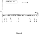
図3は、IPアドレスのプレフィクス40からのCPP IPアドレス54の構造を示す。ここで、要素41は、要素40から要素54への変換を示す。すなわち、プレフィクス「P=P0,P1,…,PK」とすると、CPPアドレスは、同じグローバルルーティングプレフィクス「P0(42)」を維持する。さらに、「Xj=Trunc(H(Kj,M)) XOR Pj(1≦j≦k)」である。ここで、「Trunc(H(Kj,M))」は、「Pj」に含まれるビット数に対して切り捨てられた「H(Kj,M)」を表す。
FIG. 3 shows the structure of the CPP IP address 54 from the
混同のおそれがない場合、単純に「H(Kj,M)」と書き、「Trunc(H(Kj,M))」を意味するものとする。図3において、要素44、46及び48は、それぞれ、「X1」、「X2」及び「Xk」を示す。そして、図3の要素54によって示されるCPPアドレスは、「A=P0,X1,X2,…,XK,Y,M」である。ここで、「52(M)」は、アドレスのサフィックスであり、「42(P0)」は、PD用のグローバルルーティングプレフィクスであり、「50(Y)」は、内部ルーティングを最適化するのに用いられる成分である。(IPv6の場合、「P0」は、最初の3ビットが「0」に設定されるように取得されることができ、アドレスのプレフィクスとホスト識別子との間の境界が、64ビット境界に該当しないことを表す。)(「Y」については、以下で論じる。)
If there is no likelihood of confusion, simply written as "H (K j, M)", it means "Trunc (H (K j, M )) ." In FIG. 3,
2つの追加ビット56(「l」及び「v」)は、上述のアドレスについてのロケーションプライバシーが保護されているか否かについてと、現在の鍵のバージョンとを表すのに用いられる。代わりに、ルーティングドメインが、ロケーションプライバシーが保護されていないIPアドレスに対応する一方の「P0」を得て、ロケーションプライバシーが保護されているアドレスに対応する他方の「P0」を得ることを可能にしてもよい。このような代替例の場合においては、別々の1ビットは必要ではない。例えば、2つの「P0」が、ビット0〜ビット46に渡って同一であり、かつ、右端の(47番目の)ビットにおいてのみ異なる場合には、プライバシードメインルータは、単に、ビット47を検査して、IPアドレスについてのロケーションプライバシーが保護されているか否かについて識別すればよい。
Two additional bits 56 (“l” and “v”) are used to indicate whether location privacy for the above address is protected and the current key version. Instead, the routing domain obtains one “P 0 ” corresponding to an IP address where location privacy is not protected, and the other “P 0 ” corresponding to an address where location privacy is protected. It may be possible. In such an alternative case, a separate bit is not required. For example, if two “P 0 ” s are the same across
上述のアドレスについてのロケーションプライバシーが保護されているか否かについて識別するのに「P0」を用いることによって、サブネット識別子の全16ビットを、非ロケーションプライバシーIPアドレス用のサブネットの識別に用いることが可能になる。そうではなく、上述したような1ビットの場合には、非ロケーションプライバシーIPアドレスは、(64ビット未満が、ホスト識別子に用いられない限り、)サブネットの識別用に使用可能な15ビットを有するのみである。鍵のバージョンのビット「v」は、どの鍵が、CPP IPアドレスを暗号化するのに用いられたかについて示すのに用いられる。 By using “P 0 ” to identify whether location privacy for the above address is protected, all 16 bits of the subnet identifier are used to identify the subnet for the non-location privacy IP address. It becomes possible. Rather, in the case of 1 bit as described above, the non-location privacy IP address only has 15 bits available for subnet identification (unless less than 64 bits are used for the host identifier). It is. Bit “v” in the key version is used to indicate which key was used to encrypt the CPP IP address.
各ルータは、3鍵期間まで、鍵を維持してもよい。すなわち、各ルータは、「現在の鍵期間」、「直前の鍵期間」、ルータが次の鍵期間用の鍵を取得している場合に必要であれば「次の鍵期間」において、鍵を維持してもよい。図4は、鍵更新の動作と、アドレス割り当て及び鍵更新の相互作用とを示す。要素150は、等しい長さの別々の期間に分割されたタイムラインを示す。一つの可能性は、各鍵期間が1日続くことである。より短いまたはより長い他の期間も、セキュリティに係る必要性及び他の理由により可能である。各ルータは、次の鍵期間154が始まるまで、次の鍵期間用の鍵を取得しなければならない。例えば、各ルータは、現在の鍵期間152の後半中に、次の鍵期間用の鍵を取得してもよい。期間i中に取得されたアドレスは、期間i+2(154)の開始前に期限が切れなければならない。期間i中に発行されたアドレスは、期間iの鍵を用いて生成される。そのため、ルータは、鍵を有していない期間中は、有効なアドレスに出会うことはない。
Each router may maintain a key for up to three key periods. That is, each router has a key in the “current key period”, “previous key period”, and “next key period” if necessary if the router has acquired a key for the next key period. May be maintained. FIG. 4 illustrates the key update operation and the interaction between address assignment and key update.
上述の構造の場合、「M」は、上記レベル鍵の生存期間中、ユニークであるべきである。換言すれば、「M」は、同じレベル鍵の集合と共に、異なるIPアドレスの部分として再使用されるべきではない。 For the structure described above, “M” should be unique for the lifetime of the level key. In other words, “M” should not be reused as part of a different IP address with the same set of level keys.
図5は、CPPが可能なプライバシードメインルータ(又は、単にCPPルータ)が従う処理手順を示す。CPPルータは、機能160において開始する。CPPルータは、機能162において、CPPルータがCPPプライバシー保護されたパケットを処理できるようにする暗号鍵を、(鍵サーバから)取得する。CPPルータは、機能164において、かかる暗号鍵を使用して、CPPパケットを転送する(164における機能は、さらに、図7に関連して本願明細書に説明されている)。CPPルータは、機能152において、鍵サーバから未使用の暗号鍵を得る。機能164において、CPPルータは、CPPパケットを転送するのを継続する。
FIG. 5 shows a processing procedure followed by a privacy domain router capable of CPP (or simply a CPP router). The CPP router starts at
CPPを利用した他の実施形態では、ISPルータが、インバウンドパケットを処理する。レベル(d−j)のルータであるルータR1が、「宛先IPアドレス:A=P0,X1,X2,…,XK,Y,M」を有するパケットを受信すると仮定する。 In other embodiments utilizing CPP, the ISP router processes inbound packets. Assume that the router R1 which is a router at the level (d−j) receives a packet having “destination IP address: A = P 0 , X 1 , X 2 ,..., X K , Y, M”.
図6に示すように、パケットも、共用秘密リンク鍵を使用して暗号化されている「P1,…,Pj」を含むホップバイホップオプション60を含む。図6に示すパケットの「種別」は、判断されることになっている。「長さ」は、(例えば、IPv6によって指定された)オプションの長さから得られる。パケットの「オフセット」は、次の解読を始めるビット位置によって示されている(このフィールドは、4ビットに縮められてもよい)。「プレフィクス長」は、「暗号化されたプレフィクス」内のビット数によって示されている(「暗号化されたプレフィクス」フィールドは、考えられ得る最長のプレフィクスを収容するために、固定長であるが、当該フィールド内の全てのビットが、必ずしも送信される「暗号化プレフィクス」の一部である必要はなく、このフィールドもまた、4ビットに縮められてもよい)。従って、「暗号化プレフィクス:=H(K,M) XOR (P1,…,Pj)」である。ここで、「K」は、共用秘密リンク鍵である。「ターゲットレベル」は、解読すべき次のレベルである。「ターゲットレベル」が「0」の場合、プレフィクスの全てのレベルが既に解読されている。
As shown in FIG. 6, the packet also includes a hop-by-
上述の共用秘密リンク鍵は、R1と直前のホップとの間で共用される。例えば、「K」を、共用秘密リンク鍵とする。そして、「H(K,M) XOR (P1,…,Pj)」は、ホップバイホップオプションの「暗号化プレフィクス」フィールド内に含まれる。 The shared secret link key described above is shared between R1 and the previous hop. For example, “K” is the shared secret link key. “H (K, M) XOR (P 1 ,..., P j )” is included in the “encryption prefix” field of the hop-by-hop option.
R1は、第1に、「ターゲットレベル」フィールド内に含まれるレベルが、R1のレベルに等しいか否かについて検査する。等しくない場合、R1は、ホップバイホップオプションからプレフィクスを得て、転送アルゴリズムに当該プレフィクスを用いる。等しい場合は、R1は、当該レベル鍵を用いて、考えられ得る最長のプレフィクス「X(j+1)」を解読する。したがって、この長さは、上述したように、予め設定されている。R1は、「X(j+1)」から「P(j+1)」を得る(すなわち、「P(j+1)=H(K(d−j),M) XOR X(j+1)」)。 R1 first checks whether the level contained in the “Target Level” field is equal to the level of R1. If not, R1 gets the prefix from the hop-by-hop option and uses that prefix in the forwarding algorithm. If they are equal, R1 uses the level key to decrypt the longest possible prefix “X (j + 1) ”. Therefore, this length is preset as described above. R 1 obtains “P (j + 1) ” from “X (j + 1) ” (ie, “P (j + 1) = H (K (d−j) , M) XOR X (j + 1) ”).
R1は、ホップバイホップオプションの「オフセット」フィールドによって識別されたビットで解読を開始する。ホップバイホップオプションから「P1,…,Pj」を得た後、R1は、「P1,…,Pj,P(j+1)」を入力プレフィクスとして、転送アルゴリズムを用いる。例示的な実施形態においては、転送アルゴリズムから次のホップ識別を得た後に、R1が、新たなホップバイホップオプション(1)〜(4)を生成する。
(1)「暗号化されたプレフィクス」フィールドに含まれる「H(Kn,M) XOR (P1,…,Pj,P(j+1))」。ここで、「Kn」は、R1が次のホップと共用する鍵である。
(2)「暗号化されたプレフィクス」の長さは、「プレフィクス長」フィールドに含まれる。「暗号化されたプレフィクス」フィールドの実際の長さは、常に16ビットであるが、リンクを横断して送信されるプレフィクスは、より短くてもよいことに注意する。「IPsec AH」を用いることが可能なため、オプション全体の長さは、一定に保持しなければならない。
(3)解読を開始する次のビットは、「オフセット」フィールドに含まれる。
(4)現在のレベル+1は、「ターゲットレベル」フィールドに含まれる。
R1 begins decoding at the bit identified by the “offset” field of the hop-by-hop option. After obtaining “P 1 ,..., P j ” from the hop-by-hop option, R 1 uses “P 1 ,..., P j , P (j + 1) ” as an input prefix and uses a transfer algorithm. In an exemplary embodiment, after obtaining the next hop identification from the forwarding algorithm, R1 generates new hop-by-hop options (1)-(4).
(1) “H (K n , M) XOR (P 1 ,..., P j , P (j + 1) )” included in the “encrypted prefix” field. Here, “K n ” is a key that R1 shares with the next hop.
(2) The length of the “encrypted prefix” is included in the “prefix length” field. Note that the actual length of the “Encrypted Prefix” field is always 16 bits, but the prefix transmitted across the link may be shorter. Since “IPsec AH” can be used, the length of the entire option must be kept constant.
(3) The next bit to start decoding is included in the “offset” field.
(4) The current level + 1 is included in the “target level” field.
本質的に、各ルータは、当該ルータのレベルに関連するプレフィクス情報を得て、かかるプレフィクス情報を用いてパケットを転送する。また、ルータは、(より上位のレベルからのプレフィクス情報と連結された)プレフィクス情報と、転送パス上の次のルータとの共用鍵で暗号化されたホップバイホップオプションにおけるオフセットとを含む。そのため、次のルータは、かかる共用鍵を用いて、より上位のレベルのルータに知られているプレフィクス部を得て、当該次のルータのレベル鍵を用いて、当該次のルータのレベルに対応するプレフィクス部を得る。これら2つのプレフィクス部の連結は、次のルータが、当該次のルータの「最長マッチ転送アルゴリズム」で用いるものである。 In essence, each router obtains prefix information related to the level of the router and forwards the packet using such prefix information. The router also includes prefix information (concatenated with prefix information from a higher level) and an offset in a hop-by-hop option encrypted with a shared key with the next router on the forwarding path. . Therefore, the next router uses the shared key to obtain the prefix part known to the higher level router, and uses the level key of the next router to reach the level of the next router. Get the corresponding prefix part. The connection of these two prefix parts is used by the next router in the “longest match transfer algorithm” of the next router.
オプションデータは、転送中に変更してもよいので、オプション種別における3番目に高いビットは「1」である。「IPsec AH」が用いられる場合、IPv6は、ビットがなくなる以外は、ホップバイホップオプションが、計算に含まれることを要する。そのため、ホップバイホップオプションのサイズは、プレフィクスのサイズに関係なく一定である(「暗号化されたプレフィクス」フィールドには、16ビットを用いることができる)。 Since the option data may be changed during transfer, the third highest bit in the option type is “1”. When “IPsec AH” is used, IPv6 requires that hop-by-hop options be included in the calculation, except that there are no bits. Therefore, the size of the hop-by-hop option is constant regardless of the size of the prefix (16 bits can be used in the “encrypted prefix” field).
CPPは、モバイルIPやHMIPv6等の処理スキームを行う場合、オーバヘッドIPトンネリングを必要としない。そのため、(モバイルIPやHMIPv6を用いた場合等のように、)追加のIPヘッダに関連する40バイトが節約される。 CPP does not require overhead IP tunneling when performing processing schemes such as Mobile IP and HMIPv6. This saves 40 bytes associated with additional IP headers (such as when using Mobile IP or HMIPv6).
以下、本発明の転送アルゴリズムについて論じる。「FWalg()」が、既存の「最長プレフィクスマッチ転送アルゴリズム(longest prefix match forwarding algorithm)」を示すものとする。IPアドレスのプレフィクスの最初のサブストリングの一致検索は、転送テーブルエントリに対して行われる(IPアドレスのプレフィクスの残りは、暗号化される)。従って、いくつかの一致検索が存在する可能性があり、それに伴ってアルゴリズムは、わずかな変更を必要とする。 The transfer algorithm of the present invention will be discussed below. “FWalg ()” indicates an existing “longest prefix match forwarding algorithm”. A match search of the first substring of the IP address prefix is performed on the forwarding table entry (the rest of the IP address prefix is encrypted). Thus, there may be several matching searches, and the algorithm accordingly requires minor changes.
パケットからの最初のサブストリングプレフィクスSが、プレフィクスを、より多くのプレフィクス成分に対して一致検索することができないことを除いて、「FWalg*()」は、「最長プレフィクスマッチングアルゴリズム」を示すものとする。換言すれば、「S」は、「S」と同数の成分を有するプレフィクス又は「S」未満の成分を有するプレフィクスのいずれかに対する一致検索に成功することができる。ここで、「S=P0,…,P(i−1),Pi」であり、「Pi」は、プレフィクス成分である。従って、「S」の一致検索結果は、(最良の一致検索結果から最悪の一致検索結果の順で、)、以下の通りである。
S
P0,…,P(i−1)
P0,…,P(i−2)
P0,…,P(i−3)
…
P0
P0,…,P(i−1),Q1
P0,…,P(i−1),Q2
…
P0,…,P(i−1),Qk
P0,…,P(i−2),Q1
P0,…,P(i−2),Q2
…
P0,…,P(i−2),Qk
…
ここで、「|Q1|≦|Q2|≦…≦|Qk|」であり、「Qi」は、プレフィクス成分である。また、「P0,…,Qi」は、全て、レベルルータによって支配される。
“FWalg * ()” is the “longest prefix matching algorithm, except that the first substring prefix S from the packet cannot match the prefix against more prefix components. ". In other words, “S” can successfully search for a match for either a prefix having the same number of components as “S” or a prefix having less than “S”. Here, “S = P 0 ,..., P (i−1) , P i ”, and “P i ” is a prefix component. Therefore, the matching search result of “S” is (in order of the best matching search result to the worst matching search result) as follows.
S
P 0 ,..., P (i−1)
P 0 ,..., P ( i-2)
P 0 ,..., P (i-3)
...
P 0
P 0 ,..., P (i−1) , Q 1
P 0 ,..., P (i−1) , Q 2
...
P 0 ,..., P (i−1) , Q k
P 0 ,..., P (i-2) , Q 1
P 0 ,..., P (i-2) , Q 2
...
P 0 ,..., P (i-2) , Q k
...
Here, “| Q 1 | ≦ | Q 2 | ≦ ... ≦ | Q k |”, and “Q i ” is a prefix component. Further, “P 0 ,..., Q i ” are all controlled by the level router.
さらに、ローカルインタフェースに対しては、厳密な一致検索が必要である(一致検索されるプレフィクスは、入力プレフィクスと等しくなければならない)。そのため、「S」が、転送テーブル内のローカルインタフェースのプレフィクスよりも長い場合には、「S」は、かかるプレフィクスと一致しない。また、パケットも、解読が行われない限り、当該パケットが到着したインタフェースから転送されない。より長いプレフィクスに対して一致検索することができないとしたのは、より長いプレフィクスが、次のプレフィクス成分を解読できないツリー内のより低いレベルのルータに対応するという考えからである。そのため、次のプレフィクス成分が解読される前に、パケットをより低いレベルのルータへ転送することは役に立たない。 Furthermore, for the local interface, a strict match search is required (the prefix that is searched for match must be equal to the input prefix). Therefore, when “S” is longer than the prefix of the local interface in the forwarding table, “S” does not match the prefix. Also, a packet is not transferred from the interface where the packet arrived unless it is decoded. The reason for not being able to match on a longer prefix is that the longer prefix corresponds to a lower level router in the tree that cannot decipher the next prefix component. Therefore, it is not useful to forward the packet to a lower level router before the next prefix component is decoded.
図7は、ルータが、変形された(CCP)転送アルゴリズムを用いてパケットを転送する本発明の実施形態を示す。プレフィクスが完全に解読されている場合、「FWalg*()=FWalg()」であることに注意する。図7に示すように、

CPP転送アルゴリズムの一例は、図7の要素164によって示される。図7の機能192に示すように、プライバシードメインルータは、入ってくるパケットから宛先IPアドレスAを得る。機能190において、アドレスAは、それがCPPアドレスであるか否かについて判断するために評価される。CPPアドレスでない場合、機能178は進行して、従来の転送アルゴリズムを用いてパケットが転送される。アドレスAがCPPアドレスである場合には、機能186は、AからプレフィクスPを得る。次いで、機能188において、プレフィクス「P」が、「P0」で始まっているか否かについて判断される。プレフィクス「P」が、「P0」で始まっていない場合、パケットは、機能180において、境界ルータへ向けてデフォルトルートの上方へ転送される。プレフィクス「P」が、「P0」で始まる場合には、170の機能が判断される。
An example of a CPP forwarding algorithm is indicated by
機能170においては、CPPオプションがあるか否かについて判断される。CPPオプションがない場合、機能194は、最適化されたルーティングを利用することを要求する。CPPオプションがある場合には、機能172は、パケットが、現在境界ルータにあるか否かについて問い合わせる。パケットがある場合には、機能184は、レベル鍵を用いて最初のPCを解読し、PCを「FWalg*()」に入力し、それに続いて、次のホップRが得られ、(Rとの)共用秘密リンク鍵を用いて、ホップバイホップオプション内でPCが暗号化される。そして、ホップバイホップオプションは、当該パケット内で転送される。
In
機能172において、CPPオプションがない場合、機能174は、共用リンク鍵を用いてホップバイホップオプションを解読し、パケットが、ホップバイホップからのターゲットレベルと等しいレベルを有するレベルルータにあるか否かについて尋ねる。かかるパケットがある場合には、機能176は、「X」の開始ビットにおいて開始することにより(この開始ビットは、ホップバイホップオプションから得られる)、アドレスのX成分から次のPCを解読する。次に、機能176は、ホップバイホップオプションのプレフィクスと新たなPCとを連結して、「Pnew(NextHop=FWalg*(Pnew))」を得る。次いで、機能176は、次のホップへ転送する前に、パケットに挿入されるホップバイホップオプションにおいて共用リンク鍵を用いて「Pnew」を暗号化する。最後に、機能176は、開始ビット及びホップバイホップオプションのターゲットレベルを更新する。
In
機能174の判断が、パケットが、ホップバイホップからのターゲットレベルに等しいレベルを有するレベルルータにないことを示す場合、機能182が用いられる。機能182は、ホップバイホップオプションからの解読されたプレフィクス(「FWalg*()」への入力プレフィクス)を用いて当該パケットを転送し、その後、ホップバイホップオプションを用いて、次のホップとの共用リンク鍵を用いて当該プレフィクスを再暗号化する。
If the determination of function 174 indicates that the packet is not at a level router having a level equal to the target level from hop-by-hop, function 182 is used. The
本発明の別の実施形態は、障害がある場合の転送アルゴリズムの復元力に対して提供する。すなわち、ルーティングリンクに障害が生じた場合には、プレフィクスが統合されるように変化する可能性がある。そのため、より低いレベルのルータは、同じレベル又はより高いレベルのルータを統合することが許されていない。この要求に対する動機は、特定のレベルのプレフィクス成分の解読が必要な場合に、より高いレベルのルータが、他のルータの転送テーブルで認識できるようにすることである。以下の証明のため、非レベルルータは、ルーティングリンクに障害が生じた場合でも、統合を行わない。 Another embodiment of the invention provides for the resiliency of the transfer algorithm in the event of a failure. That is, when a failure occurs in the routing link, there is a possibility that the prefix is changed to be integrated. As such, lower level routers are not allowed to consolidate the same or higher level routers. The motivation for this request is to allow higher level routers to recognize in the forwarding table of other routers when a certain level of prefix component needs to be decoded. Due to the following proof, the non-level router does not integrate even if the routing link fails.
図8は、IPアドレスのプレフィクスが、6ビットを有し(6ビットのうちの2ビットが、サブネット識別子用に用いられる)、転送アルゴリズムが、ある程度の数の障害がある場合を含み、パケットを当該パケットの宛先へ転送することに成功することができるCPPアクセスネットワークの一例を示す。各リンクには、当該リンク上の下位のルータによって通知されるプレフィクスがラベル付けされている。例えば、ルータR3(要素60)は、プレフィクス64(「10101」)を62(ルータR1)に対する上方に通知する。図8においては、R3が故障することが想定される。そして、さらに、プレフィクス「101010」を有するパケットを想定する。R1は、最初のビットを解読して「10101」を得る。R3が故障失敗した場合、R1の転送テーブルは、
「10100 R2」
「101010 R7」
「101011 R7」
「1010 ローカル」
になる。
FIG. 8 shows the case where the IP address prefix has 6 bits (2 of the 6 bits are used for the subnet identifier) and the forwarding algorithm has a certain number of failures Shows an example of a CPP access network that can be successfully transferred to the destination of the packet. Each link is labeled with a prefix notified by a lower router on the link. For example, the router R3 (element 60) notifies the prefix 64 (“10101”) upward to 62 (router R1). In FIG. 8, it is assumed that R3 fails. Further, a packet having the prefix “101010” is assumed. R1 decrypts the first bit to get “10101”. If R3 fails, the forwarding table for R1 is
"10100 R2"
"101010 R7"
"101011 R7"
“1010 Local”
become.
これらのプレフィクスは、「10101」よりも長いため、「10101」は、「101010」又は「101011」に対して一致検索することができない。(このような一致検索が許されていると、パケットは、次のビットを解読できないグラフ内の下位のレベルのルータへ送られることになる。そのため、発明者らは、上述の転送アルゴリズムにおけるこのような一致検索を認めない。) Since these prefixes are longer than “10101”, “10101” cannot be matched with “101010” or “101011”. (If such a match search is allowed, the packet will be sent to a lower level router in the graph where the next bit cannot be deciphered. Does not allow such matching search.)
その代わりに、「10101」は、(最後の「0」が除去された場合、)「10100」に対して一致検索する。かかるパケットは、後に解読してプレフィクス「101010」を得るルータR2に転送される。そして、このプレフィクスは、R2の転送テーブル:
「10100 ローカル」
「101010 R1」
「101011 R1」
「1010 R1」
「101000 R4」
「101001 R5」
において、当該プレフィクス自体に一致する。
Instead, “10101” searches for a match with “10100” (if the last “0” is removed). Such a packet is forwarded to the router R2 which is later decrypted to obtain the prefix “101010”. And this prefix is the R2 forwarding table:
“10100 Local”
"101010 R1"
"101011 R1"
"1010 R1"
"101000 R4"
"101001 R5"
In the above, it matches the prefix itself.
そして、当該パケットは、その後、R1へ転送される。次いで、R1は、プレフィクスをR7に対して一致検索して、当該パケットをR7へ転送する。R7は、当該パケットをローカルインタフェースで転送する。こうして、当該パケットは、ルータR3の故障にも関わらず配信される。 The packet is then transferred to R1. R1 then matches the prefix to R7 and forwards the packet to R7. R7 transfers the packet through the local interface. Thus, the packet is distributed despite the failure of the router R3.
本発明は、一定条件下における次の提案(Lemma4.1)によって立証されるような転送アルゴリズムの頑強性も提供する。パケットPが、境界ルータ又はアクセスルータ(エントリポイントルータ)のいずれかを介して、プライバシードメインに到着すると仮定する。また、パケットPが、レベル(i+1)ルータQを通過し、当該パケットを処理する次のレベルルータRが下方にある場合(Rが、Qと同じ接続成分にはない場合)、Rは、Qと同じ接続成分において兄弟関係のルータを有すると仮定する。ここで、兄弟関係は、Qの子孫でもあるレベルiを有する別のルータとして定義される。そして、当該パケットは、転送プロセス中に、完全に解読される(全てのレベル鍵が適用され、プレフィクス全体がルータに対して使用可能になる)。 The present invention also provides robustness of the transfer algorithm as evidenced by the following proposal (Lemma 4.1) under certain conditions. Assume that packet P arrives in the privacy domain either through a border router or an access router (entry point router). Also, if the packet P passes through the level (i + 1) router Q and the next level router R that processes the packet is below (when R is not in the same connection component as Q), R is Q Assume that we have sibling routers in the same connected component. Here, a sibling relationship is defined as another router having level i that is also a descendant of Q. The packet is then completely decrypted during the forwarding process (all level keys are applied and the entire prefix is available to the router).
立証として、パケットPが、境界ルータに到達すると仮定する。帰納法を用いて、プレフィクス成分「P1,…,Pi」が解読されていると仮定する。Pは、レベル(d−i)のルータへ転送されることが分かっている。Riは、「Pi」を解読したレベル(d−i+1)のルータとする。プレフィクス「P1,…,Pi」を有するルータである元のスパニングツリーにおいて、Rを選択する。Rは、レベル(d−i)を有する。 As a proof, assume that packet P reaches the border router. Assume that the prefix component “P 1 ,..., P i ” has been deciphered using induction. P is known to be forwarded to the router at level (d−i). R i is a router at a level (d−i + 1) obtained by decoding “P i ”. Select R in the original spanning tree, which is a router with the prefix “P 1 ,..., P i ”. R has a level (d−i).
ケースa:Rが、上方にあり、Riと同じ接続成分にある。RiからRへのパスがあり(統合が行われない場合)、最少のコストのパスを選択し、かかるパスをAと呼ぶ。次に、「P1,…,Pi」は、かかるパスに沿った各ルータ用の転送アルゴリズムにおいて的確に一致する。そのため、Pは、要望通りに、Rへ転送されることになる。 Case a: R is in the upward, in the same connection component as R i. There is a path from R i to R (when integration is not performed), the path with the lowest cost is selected, and this path is called A. Next, “P 1 ,..., P i ” exactly matches in the forwarding algorithm for each router along the path. Therefore, P is transferred to R as desired.
さもなければ、RiからRへの最少の統合及びコストを伴うパスAを選ぶ。RiからRへのパスにおいては、「T1,…,Tk」を統合を行うルータとする。そして、「Ti」により通知されるプレフィクスは、「T(i−1)(T0=Ri)」用の転送アルゴリズムにおいて、一致検索に成功することになる。この最後の言及は、最少の統合を伴うパスを選んだということから当然の結果である。そのため、Pは、要望通りに、Rへ転送される。 Otherwise, choose path A with minimal integration and cost from R i to R. In the path from Ri to R, “T 1 ,..., T k ” is a router that performs integration. The prefix notified by “T i ” succeeds in the matching search in the transfer algorithm for “T (i−1) (T 0 = R i )”. This last mention is a natural consequence of choosing the path with the least integration. Therefore, P is forwarded to R as desired.
ケースb:Rは、異なる接続成分にある。仮定により、Riは、Rと同じレベルを有するルータTと同じ接続成分にある。そして、「T」は、「P1…P(i−1),Q」を通知する。「P1…P(i−1),Q」は、(Riの転送テーブル内の)Riに対して認識できるか、または、統合されたプレフィクス「P1,…,Pj」は、認識できる。最初のケースの場合、認識できる統合されたプレフィクスがない場合、「P1,…,P(i−1),Q」が、一致検索結果する。このような一致検索は、Riと「T」との間のルータのつながりにおいて継続し、その結果、「T」へ転送されるパケットPを生じる。そして、「T」は、要望通りに、当該パケットを解読する。 Case b: R is in a different connected component. By assumption, R i is in the same connected component as router T, which has the same level as R. Then, “T” notifies “P 1 ... P (i−1) , Q”. "P 1 ... P (i-1 ), Q 'is (in the forwarding table of R i) or can be recognized with respect to R i, or integrated prefix" P 1, ..., P j' is Can be recognized. In the case of the first case, if there is no recognizable integrated prefix, “P 1 ,..., P (i−1) , Q” results in a match search. Such a match search continues in the router connection between R i and “T”, resulting in packet P being forwarded to “T”. “T” then decrypts the packet as desired.
ここで、統合されたプレフィクス「(P1,…,Pj)」が、Riに認識できると仮定する。この最良の一致検索は、解読が行われるまで(及び、立証が完了するまで)、又は、より長いプレフィクス成分シーケンス(「P1…Pk」、ここで、「k>j」)が登場するまで、続けられる。さらに、最良の一致検索は、解読が行われるまで(及び、立証が完了するまで)、又は、より長いプレフィクス成分シーケンスが登場するまで、続けられる。最後に、あるプレフィクス成分「Q1」に対して、「P1,…,P(i−1)」とならなければならない。以前に対する最良の一致検索は、このプレフィクスを有するルータが、上述の転送アルゴリズムについての言及によるレベルルータであるルータに到達されるまで続けられる(このルータは、適切なレベル鍵を有する兄弟ルータである)。そのため、次の成分が解読され、立証が完了する。 Here, it is assumed that the integrated prefix “(P 1 ,..., P j )” can be recognized by R i . This best match search will appear until decryption occurs (and until verification is complete) or a longer prefix component sequence ("P 1 ... P k ", where "k>j") Until you do. In addition, the best match search continues until decryption occurs (and verification is complete) or until a longer prefix component sequence appears. Finally, for some prefix component “Q 1 ”, it must be “P 1 ,..., P (i−1) ”. The best match search against before is continued until a router with this prefix reaches a router that is a level router by reference to the forwarding algorithm above (this router is a sibling router with the appropriate level key). is there). Therefore, the next component is decoded and the verification is completed.
さらに、パケットが、境界ルータ又はアクセスルータ(エントリポイントルータ)のいずれかを介して、上記プライバシードメインに到達すると仮定し、かつ、「(上述した)Lemma4.1」の条件を保持すると仮定する。そのため、当該パケットは、宛先のアクセスルータへ配信される。立証として、「Lemma4.1」及び既存の最長プレフィクスの特性が、ルーティングアルゴリズムに一致すると考える(プレフィクスが、一旦完全に解読されると、「FWalg*()=Fwalg()」)。 Further assume that a packet reaches the privacy domain via either a border router or an access router (entry point router) and maintains the condition “Lema 4.1” (described above). Therefore, the packet is distributed to the destination access router. As a proof, we consider that the characteristics of “Lema 4.1” and the existing longest prefix are consistent with the routing algorithm (“FWlg * () = Fwalg ()” once the prefix is fully decrypted).
別の実施形態においては、統合に対する要求の1つを緩和することが可能であり、それにより、本願明細書において正規化と呼ぶプロセスにおいて、追加の統合が可能になる。追加の統合の利点には、プライバシーの向上及びルータ転送テーブルにおけるエントリの数のさらなる低減が含まれる。本実施形態において、プレフィクスの所有権についての必要条件は緩和される(この場合、所有するルータは、当該プレフィクスに対する統合を行っているルータ、或いは、当該プレフィクスと等しいIPアドレスを有するルータである)。すなわち、統合を行っているルータのサブツリーにおけるルータは、プレフィクスの所有権を所有する必要はない。それに伴って、統合されたプレフィクスは、スパニングツリー「T」内にないリンクを横断して通知されるルートを含んでもよく、その代わり、当該リンクは、ルーティンググラフ「G」に含まれてもよい。 In another embodiment, one of the requirements for integration can be relaxed, thereby allowing additional integration in a process referred to herein as normalization. Additional integration benefits include increased privacy and a further reduction in the number of entries in the router forwarding table. In the present embodiment, the requirement for ownership of a prefix is relaxed (in this case, the owning router is a router that performs integration for the prefix, or a router having an IP address equal to the prefix) Is). That is, the routers in the subtree of the router that is performing the integration need not own ownership of the prefix. Accordingly, the integrated prefix may include routes that are advertised across links that are not in the spanning tree “T”; instead, the links may be included in the routing graph “G”. Good.
図9は、プライバシードメインルーティンググラフ「G」の一部を示す正規化の一例を示す。この例もまた、プレフィクス内において限定された数のビットを用いる。しかし、リンク80が、元のスパニングツリー「T」内に存在しないリンクであることに注意する。そのため、要素76(ルータR2)が、リンク80を受け入れた場合には、上述したような厳密な統合は起こらない。すなわち、ルータR2が、統合用のプレフィクス「10100」及び「101011」の通知を受け取るのみである場合、通常の統合である。しかし、「101010」は、ルータR2をルートとするサブツリーの外にあるので、ルータR2は、ルータR8からのリンク「101010」の受け入れのため、統合の通常の規則に従わないことになる。
FIG. 9 shows an example of normalization showing a part of the privacy domain routing graph “G”. This example also uses a limited number of bits in the prefix. However, note that
統合の必要条件を緩和することにより、ルータR2は、(80によって通知された「101010」と共に、)プレフィクス「10100」及び「101011」をルータR1における「1010」と統合できるようになる。そのため、要素72(ルータR1)では、R1の転送テーブルにおいて、1つエントリが減ることになる。プライバシーの観点から、R1は、もはや、パケットが、82(ルータ7)に向けられているか否かについて検出することはできなくなる。従って、ルータR2(要素76)が、(要素80に通知された「10101」と共に、)プレフィクス「10100」及び「101011」を「1010」に正規化できるようにした場合、プライバシーは向上する。 By mitigating the integration requirement, router R2 can integrate prefixes “10100” and “101011” (with “101010” notified by 80) with “1010” in router R1. Therefore, in the element 72 (router R1), one entry is reduced in the forwarding table of R1. From a privacy point of view, R1 can no longer detect whether the packet is destined for 82 (router 7). Therefore, privacy is improved when the router R2 (element 76) is able to normalize the prefixes “10100” and “101011” (together with “10101” notified to the element 80) to “1010”.
本発明者等は、ルータR2が「1010」に正規化して通知できるようにすることに関して問題がある可能性があることに注目した。要素70は、リンク74によって「101010」を72(ルータR1)に対する上方へ通知する。要素72は、「1010」が意図されたプレフィクスであるかどうか、又は、「101010」を生じる2つの追加ビットの解読が意図されたプレフィクスであるかどうかについて検知することができなくてもよい。すなわち、意図されたプレフィクスは、「101011」であってもよいし、「101010」であってもよい。「101010」の解読結果は、最後の2ビットが、ルータR2の鍵に従って暗号化された「101011」であってもよい。この問題は、「1010」を「10100」として符号化することにより解決することができる。従って、この符号化を用いて、ルータR1は、2つの追加ビットを解読する(ルータR1は、「1010」をホップバイホップオプションで受け取る)。
The present inventors have noted that there may be a problem with enabling the router R2 to normalize and notify “1010”.
このように、ルータR1が上述の解読から得るビットパターンは、「0x」又は「10」のいずれかである。ここで、「x」は、「0」又は「1」とすることができる。第1のケース(「x=0」)においては、パケットは、「1010」をプレフィクスとして含むホップバイホップオプションを用いて、要素76(ルータR2)へ転送される。ここで、符号化されたプレフィクス(「10100」)が送信されるのではなく、転送テーブルのプレフィクスに対応する実際のプレフィクス「1010」が送信される。従って、「10100」は、「1010」に対してマッピングされる。第2のケース(「x=1」)においては、パケットは、「101010」のホップバイホッププレフィクスを用いて、要素70(ルータR8)へ転送される。 Thus, the bit pattern obtained by the router R1 from the above-described decryption is either “0x” or “10”. Here, “x” can be “0” or “1”. In the first case (“x = 0”), the packet is forwarded to element 76 (router R2) using a hop-by-hop option that includes “1010” as a prefix. Here, the encoded prefix (“10100”) is not transmitted, but the actual prefix “1010” corresponding to the prefix of the forwarding table is transmitted. Therefore, “10100” is mapped to “1010”. In the second case (“x = 1”), the packet is forwarded to element 70 (router R8) using a hop-by-hop prefix of “101010”.
統合前、要素76(ルータR2)は、レベルを伴わないルータであり、要素72(ルータR1)は、レベル2のルータである。要素76は、統合を行うことができるようになった後、レベル2のルータとなり、要素72は、レベル3ルータとなる。72より上位の全てのルータは、当該ルータのレベルを1だけ増す。要素78(ルータR4)は、統合の前後において、レベル1を有している。プレフィクス成分(PC)の符号化を用いて、2つの異なるPCの集合が導入される。第1の集合は、上述の転送テーブル内のプレフィクスの一部である実際のPCである。第2の集合は、CPPアドレスにおいて暗号化されている集合である。第1の集合は、「C_R」と設定され、第2の集合は、「N_R」と設定されており、この符号化方法は、「正規化」と呼ばれている。
Before integration, element 76 (router R2) is a router without a level, and element 72 (router R1) is a
追加の統合が導入された場合、統合を行っている頂点をルートとするスパニングツリーのサブツリー内の統合を行っているルートのみに関して、統合の制約を緩和することにより、レベルが、ルーティンググラフ「G」内で生じる。レベルルータではないルータRが、ここで1つになると仮定する。Rをルートとするサブツリー内のルータは、同じレベルを保持する。Rは、(スパニングツリー内の)Rの子よりも大きいレベルを有する。当該グラフ「G」内の他のレベルのルータは、全て、1だけ増加したレベルを有する。当然、統合を行っている頂点が、既にレベルルータである場合には、ルータのレベルは変化しないことに注意する。 When additional integrations are introduced, the level is reduced to the routing graph “G” by relaxing the integration constraints for only the integration routes in the spanning tree subtree rooted at the integration vertex. Occurs within. Assume that there is one router R that is not a level router. Routers in the subtree rooted at R maintain the same level. R has a higher level than its children (in the spanning tree). All other levels of routers in the graph “G” have a level increased by one. Of course, if the vertex that is performing the integration is already a level router, note that the router level does not change.
PCの正規化された集合は、各ルータに対するプレフィクスにおいて符号化されることが要求される。PCの正規化された集合を用いて、PCは、他のPCのプレフィクスとすることができない。そのため、PCを解読する場合、曖昧さはない。正規化されたPCを解読した後、(集合「N_R」に属する)正規化されたPCは、ルータR用のPCの元の集合「C_R」内のPCにマッピングされ得る。 A normalized set of PCs is required to be encoded in the prefix for each router. Using a normalized set of PCs, a PC cannot be a prefix of another PC. Therefore, there is no ambiguity when decrypting a PC. After decrypting the normalized PC, the normalized PC (belonging to the set “N_R”) may be mapped to a PC in the original set “C_R” of PCs for router R.
ここで、「C_R」を、ルータRにおけるPCの集合とする。ユーザホスト用のサブネットワークを識別するプレフィクスを「P」であると仮定する。「P」を、「P=P1|P2|P3|…|Pk」と書くことができる。ここで、「|」は、連結を示し、「P1|P2|…|Pi」は、(d−i)番目のレベルのルータ用の一致検索を行うプレフィクスである。(d−i)番目のレベル用の鍵を「Ki」で表す。 Here, “C_R” is a set of PCs in the router R. Assume that the prefix identifying the sub-network for the user host is “P”. “P” can be written as “P = P 1 | P 2 | P 3 |... | P k ”. Here, “|” indicates concatenation, and “P 1 | P 2 |... | P i ” is a prefix for performing a matching search for the (d−i) -th level router. The key for the (d−i) th level is represented by “K i ”.
ルータRにおける可能性の有る「Pi」の集合は、「C_R」である。この場合、「C_R」の正規化されたバージョンが必要である。「N_R」は、以下に示す「Definition6.2」の特性を満たす集合である。
「Definition6.1」:ストリングSが、ストリングTのプレフィクスである場合、(S,T)が、プレフィクス対である。
「Definition6.2」:「N_R」は、集合であり、全単射f(全単射は、1対1及び上への関数である)は、次の特性を満たす。
- 全単射f:N_R≧C_R
- 「N_R」の構成員である任意の2つのストリング「S」及び「T」に対して、「S」は、「T」のプレフィクスではない。
A set of possible “P i ” in the router R is “C_R”. In this case, a normalized version of “C_R” is required. “N_R” is a set satisfying the characteristics of “Definition 6.2” shown below.
“Definition 6.1”: When string S is a prefix of string T, (S, T) is a prefix pair.
“Definition 6.2”: “N_R” is a set, and bijection f (bijection is a function of one-to-one and up) satisfies the following characteristics.
-Bijection f: N_R ≧ C_R
-For any two strings "S" and "T" that are members of "N_R", "S" is not a prefix of "T".
「C_R」が、「S」が「T」のプレフィクスであるようなストリング「S」及び「T」を有していない場合、「N_R=C_R」である。さもなければ、あるストリング「T」のプレフィクスである「C_R」におけるストリング「S」を想定する。ここで、「T」は、「S」がプレフィクスである「C_R」における全てのストリングのうちの最短のものである。 If “C_R” does not have strings “S” and “T” such that “S” is a prefix of “T”, then “N_R = C_R”. Otherwise, assume string “S” in “C_R”, which is a prefix of some string “T”. Here, “T” is the shortest of all strings in “C_R” where “S” is a prefix.
集合「E={SR:Rは、ストリングであり、|SR|=|T|である}」は、「C_R」に含まれていない。さもなければ、「最長プレフィクスマッチルーティングアルゴリズムは」、ストリング「S」を選択しない。「|SY|=|T|」となるように、「E」内にはない「Y」を選択する。集合「C_R」から「S」を取り除いて、「SY」を新たな集合「N1_R」に加える。 The set “E = {SR: R is a string and | SR | = | T |}” is not included in “C_R”. Otherwise, “Longest prefix match routing algorithm” does not select the string “S”. “Y” not in “E” is selected so that “| SY | = | T |”. Remove “S” from the set “C_R” and add “SY” to the new set “N1_R”.
それに応じて、第1の命題は、「N1_R」が、「C_R」よりも厳密に少ないプレフィクス対を含むことを提示する。第2の命題は、「S」に対する「SY」のマッピングを除いて「N1_R」上の識別であるマッピング「f1:N1_R→C_R」が全単射であることを提示する。第2の命題は、明白である。第1の命題は、「SY」が「S」よりも厳密に少ないストリングのプレフィクスである(「SY」は、「T」のプレフィクスではない)ため、理解される。また、「SY」のプレフィクスである任意のストリングは、「S」である、「S」のプレフィクスである、又は、「S」よりも大きいが「Y」よりも小さい長さを有する。最後のケースは、「T」が、「S」が「T」のプレフィクスである最短のストリングであるため、不可能である。最初のケースは、「S」が「N1_R」内にないため、不可能である。 Accordingly, the first proposition presents that “N1_R” contains strictly fewer prefix pairs than “C_R”. The second proposition presents that the mapping “f1: N1_R → C_R”, which is the identification on “N1_R”, except for the mapping of “SY” to “S” is bijective. The second proposition is obvious. The first proposition is understood because “SY” is a string prefix that is strictly less than “S” (“SY” is not a prefix of “T”). Also, any string that is a prefix of “SY” is a prefix of “S”, a prefix of “S”, or has a length greater than “S” but less than “Y”. The last case is not possible because “T” is the shortest string where “S” is a prefix of “T”. The first case is not possible because “S” is not in “N1_R”.
(新たに生成された各集合は、直前のものよりも少ないプレフィクス対を有するので、終わらせなければならない)直前の構造は継続される。したがって、「C_R≧N1_R≧…≧Nk_R=N_R」が得られ、「N_R」が、「N_R」から「C_R」への全単射を伴う所望の集合となる。 (Each newly created set has fewer prefix pairs than the previous one, so it must be terminated.) The previous structure continues. Therefore, “C_R ≧ N1_R ≧... ≧ Nk_R = N_R” is obtained, and “N_R” becomes a desired set with bijection from “N_R” to “C_R”.
「N_R」は、暗号化されたプレフィクス成分のコンパクトな符号化を提供する。具体的には、各ルータは、考えられ得る最長のプレフィクスを解読することができ、その後、どのような曖昧さに対する心配も伴うことなく、一致するものを探索することができる。「N_R」は、プレフィクス成分の符号化に用いられる。ルータは、「N_R」のストリングを「C_R」のストリングにマッピングして、上述の転送アルゴリズム用の適切な一致するストリングを得る(そのため、転送テーブルのエントリは、このようなマッピング及び符号化に影響を及ぼされない)。しかし、プレフィクス成分の符号化は、実際のプレフィクスよりも多少長くてもよいことに注意する。ルーティングトポロジー及びプレフィクスが、統合の量を最大化するように設定されている場合、サイズの増加の程度は、最少にされ得る、或いは、無視され得る。 “N_R” provides a compact encoding of the encrypted prefix component. Specifically, each router can decipher the longest possible prefix and then search for a match without worrying about any ambiguity. “N_R” is used for encoding a prefix component. The router maps the “N_R” string to the “C_R” string to obtain an appropriate matching string for the forwarding algorithm described above (so forwarding table entries affect such mapping and encoding). Is not affected). However, note that the encoding of the prefix component may be slightly longer than the actual prefix. If the routing topology and prefix are set to maximize the amount of integration, the degree of size increase can be minimized or ignored.
本発明の別の実施形態は、最適化されたルーティングを提供する。パケットが、上記プライバシードメイン内で、アクセスルータに接続されたホストから異なるアクセスルータに接続された別のホストへ送られる場合、最適な転送パスは、境界ルータを通過するパケットを必要としない場合が多い。CPP用の1つのパフォーマンス尺度は、CPPが用いられない場合に存在する最適な転送パスが、どの程度、CPPを用いてなお使用されているかということである。上述したアルゴリズムの場合、入ってくるパケットは、常に、境界ルータのうちの1つを通過する。 Another embodiment of the present invention provides optimized routing. If a packet is sent from a host connected to an access router to another host connected to a different access router within the privacy domain, the optimal forwarding path may not require the packet to pass through a border router. Many. One performance measure for CPP is how much the optimal forwarding path that exists when CPP is not used is still used with CPP. For the algorithm described above, incoming packets always pass through one of the border routers.
本発明においては、(1)境界ルータ上のトラヒック負荷を低減すること、及び、(2)CPPで保護された宛先アドレスを有するパケットが通過するルータの数を低減することが好ましい。上述のロケーションプライバシーが保護されたIPアドレスが、「A=(P0,Y,X,M)」であることを思い起こす。ここで、「Y」は、イントラドメイン通信を最適化するのに利用可能である。「Y」は、およそ16〜36ビットになると予想される(「P0」は、32又は48ビットのいずれかであり、「X」は、おおよそ16ビットである。「X」は、正規化が行われる場合、16ビットよりも少し長くすることができることに注意する。また、「Y」も、ツリー上に多数のルートがある場合には、少し長くすることができる。従って、「M」は、およそ18〜24ビットである)。 In the present invention, it is preferable to (1) reduce the traffic load on the border router, and (2) reduce the number of routers through which a packet having a destination address protected by CPP passes. Recall that the above-mentioned location privacy protected IP address is “A = (P 0 , Y, X, M)”. Here, “Y” can be used to optimize intra-domain communication. “Y” is expected to be approximately 16-36 bits (“P 0 ” is either 32 or 48 bits and “X” is approximately 16 bits. “X” is normalized Note that “Y” can be a little longer than 16 bits, and “Y” can also be a little longer if there are many roots on the tree. Is approximately 18-24 bits).
本発明の様々な実施形態による最適化されたルーティング用の例は、基本的な例、高度化された基本的な例、最適化された例、最適化された例の特別なサブケース、及び最適化された例の鍵ハッシュ変形例を含む。以下、これらについて論じる。 Examples for optimized routing according to various embodiments of the present invention include basic examples, advanced basic examples, optimized examples, special sub-cases of optimized examples, and Includes a key hash variant of the optimized example. These are discussed below.
上述の基本的な例においては、「Y」は、ホスト用のアクセスルータと、当該アクセスルータの親ルータとの間の共用鍵で暗号化されたIPアドレスのプレフィクスによって構成されている。ここで、アクセスルータは、(通常、発信元アドレスのプレフィクスを解読して調べることにより、)「イングレスフィルタリング」を行う。親ルータは、宛先アドレスを解読して、当該親ルータの子アクセスルータのうちの1つへ転送すべきか否かについてチェックすることにより、当該宛先アドレスをチェックして、(そのアクセスルータが、共通の親ルータを共用するホスト用に)限定された最適化ルーティングを可能にする。 In the basic example described above, “Y” is configured by a prefix of an IP address encrypted with a shared key between the host access router and the parent router of the access router. Here, the access router performs “ingress filtering” (usually by decoding and examining the prefix of the source address). The parent router checks the destination address by decrypting the destination address and checking whether it should be transferred to one of the child access routers of the parent router. Allows limited optimization routing (for hosts sharing the parent router).
上述の高度化された基本的な例においては、「Y」は、アクセスルータの2レベル上であるルータと、当該ルータの子との間で共用される鍵で暗号化されたIPアドレスのプレフィクスによって構成されている。ここで、アクセスルータの親は、アクセスルータのフィルタを直接用いて、或いは、(より粗い)統合フィルタを用いて、「イングレスフィルタリング」を行う。これらのルータの両方は、それらのサブツリー内のルーティングを最適化することができる。上述の高度化された基本的な例に関しては、親又は祖父のいずれかの障害は、祖父の下の全てのホストに対するロケーションプライバシーの潜在的な損失をもたらすため、安全性は低下する。 In the advanced basic example described above, “Y” is the IP address pre-encrypted with a key shared between the router two levels above the access router and the child of the router. It is composed of fixtures. Here, the parent of the access router performs “ingress filtering” using the filter of the access router directly or using a (coarser) integrated filter. Both of these routers can optimize routing within their subtrees. For the above sophisticated basic example, the failure of either the parent or grandfather results in a potential loss of location privacy for all hosts under the grandfather, thus reducing safety.
上述の基本的な例及び高度化された基本的な例の利点は、「Y」が16ビットを要するのみなので、2つの例とも実装が容易であることである。加えて、以下にさらに説明する完全に最適化されたルーティングの例は、より大きな解読演算を必要とする。 The advantage of the basic example and the advanced basic example described above is that both examples are easy to implement because “Y” only requires 16 bits. In addition, the fully optimized routing example described further below requires larger decryption operations.
上述の基本的な例及び高度化された基本的な例に関して、本発明者等が注目した潜在的な問題は、間違った暗号鍵が用いられた場合で、かつ、解読されたプレフィクスが、偶然に、上述の転送テーブル内のプレフィクスに一致した場合に、パケットが、間違ったルートで転送されかねないことである。このような可能性は、転送テーブル内のプレフィクスの数に依存し、プレフィクスは、単に16ビットであるため、この可能性は、いくつかのネットワークにとってはかなり高くなり得る。 With respect to the basic example and the advanced basic example described above, the potential problem we have noted is that the wrong encryption key is used and the decrypted prefix is Coincidentally, a packet can be forwarded on the wrong route if it matches a prefix in the forwarding table described above. Such a possibility depends on the number of prefixes in the forwarding table, and since the prefix is only 16 bits, this possibility can be quite high for some networks.
図10は、最適化されたルーティングの例を示す。本実施形態において、内部のホストから送られたパケットは、宛先アドレスに対する最適なパスの一部であるルータに到達するまで、ルーティンググラフの上方に転送される。このルータは、「クロスオーバルータ」と呼ばれている。パケットは、このポイントで下方へルーティングされるべきである。クロスオーバルータRは、「Y」成分のセグメント(実際には、「W(j,k)=U(j,k) XOR H(Nj,M,Xj)」)に対して、(上述したように、当該クロスオーバルータRのレベル鍵を用いて、)標準的なXORを実行して、ローカルシークレット「U(j,k)」を得ることにより、このパケット用のクロスオーバルータであることを識別する。結果が、当該シークレットと一致する場合、Rは、それがクロスオーバルータであることを知る。 FIG. 10 shows an example of optimized routing. In this embodiment, a packet sent from an internal host is transferred above the routing graph until it reaches a router that is part of the optimum path for the destination address. This router is called a “crossover router”. Packets should be routed down at this point. The crossover router R (for the “Y” component (actually, “W (j, k) = U (j, k) XOR H (N j , M, X j )”)) As described above, using the level key of the crossover router R, a standard XOR is performed to obtain the local secret “U (j, k)”, thereby obtaining the crossover router for this packet. Identify that. If the result matches the secret, R knows that it is a crossover router.
その後、クロスオーバルータRは、「Z」の最初の部分(ここで、「Y=(W,Z)」)を解読して、最初のプレフィクス部分を得る。次いで、Rは、インバウンド転送用の上述のアルゴリズムを用いて、パケットを転送する。図10は、上述のプライバシールーティングドメイン内の90に接続されたホストによって、同じドメイン内の92に接続された他のホストへ送信されるパケットPkt用の最適な転送パスを示す。パケットPktは、94を含むいくつかのルータにより、(境界ルータ98へ向けて)デフォルトルートの上方へ転送される。ルータ96は、「W(3,k3)」及び「U(3,k3)」を調べることにより、ルータ96より下のサブツリー内のホストに、Pktの宛先が指定されていることを判断した後、Pktをシークレット「U(4,k4)」と共に、当該ルータへ転送する。従って、96は、パケットPkt用のクロスオーバルータである。その後、Pktは、92に到達するまで、連続するルータにより、ツリーの下方へ転送される。
The crossover router R then decrypts the first part of “Z” (where “Y = (W, Z)”) to obtain the first prefix part. R then forwards the packet using the algorithm described above for inbound forwarding. FIG. 10 shows the optimal forwarding path for a packet Pkt sent by a host connected to 90 in the privacy routing domain described above to another host connected to 92 in the same domain. Packet Pkt is forwarded above the default route (toward border router 98) by several routers, including 94. The
(安全性の低下という犠牲を払った)さらなる最適化として、クロスオーバシークレットは、共用リンク(ルータグラフ内のクロスリンク)上で同じレベルの他の少数のルータと共用され得る。この共用によって、これらの隣接するルータが、パケットを迅速にクロスオーバルータへ転送することができる。 As a further optimization (at the expense of reduced security), the crossover secret can be shared with a few other routers at the same level on a shared link (crosslink in the router graph). This sharing allows these neighboring routers to quickly forward the packet to the crossover router.
上述したように、最適化されたルーティング用のCPPアドレスの成分は、追加の必要条件を、IPアドレス内の使用可能なビットに対して課す。図11は、使用可能なビットに対して課された、考えられ得る必要条件を含む例示的なIPアドレス指定を示す。 As mentioned above, the optimized routing CPP address component imposes additional requirements on the available bits in the IP address. FIG. 11 shows an exemplary IP addressing including possible requirements imposed on the available bits.
「M」に必要とされるビット数を低減することが好ましいと考える。以下の例は、「M」が、所定のサブネット内でユニークであることを必要とするのみである。換言すれば、同じプレフィクスを有する2つのCPP IPアドレスは、「M」に対して異なる値を有していなければならず、そうでない場合、2つのアドレスは、「M」に対して同じ値を有することができる。それに伴って、この以下のアルゴリズムは、「M」のサイズを約16〜22ビットに低減すると予想される。
上述のように、プレフィクス成分「P0,P1,…,Pk」を有するIPアドレスを仮定すると、拡張されたCPP IPアドレスは、「P0,v,X1,X2,…,Xk,Y,M」である。ここで、「Xk=H(Kk,M,P1,…,P(k−1)) XOR Pk」、「X(k−1)=H(Kk−1,M,Xk) XOR P(k−1)」、…、「X1=H(K1,M,X2) XOR P1」となる。
We consider it preferable to reduce the number of bits required for “M”. The following example only requires that “M” be unique within a given subnet. In other words, two CPP IP addresses with the same prefix must have different values for “M”, otherwise the two addresses have the same value for “M” Can have. Accordingly, this following algorithm is expected to reduce the size of “M” to about 16-22 bits.
As described above, assuming an IP address having a prefix component “P 0 , P 1 ,..., P k ”, the expanded CPP IP address is “P 0 , v, X 1 , X 2 ,. Xk , Y, M ". Here, “X k = H (K k , M, P 1 ,..., P (k−1) ) XOR P k ”, “X (k−1) = H (K k−1 , M, X k ) XOR P (k−1) ”,...,“ X 1 = H (K 1 , M, X 2 ) XOR P 1 ”.
図11は、要素101を用いて、IPv6アドレスのプレフィクス100からCPPアドレス114への構造について示す。図11において、「Z=P1 XOR H(T2,M,X1)|P2 XOR H(T3,M,X2)|…|Pk−1 XOR H(Tk,M,Xk−1)」である。ここで、「Ti=HMAC(Li,L1|L2|…|L(i−1))、1≦i≦k」であり、例えば、「L1」は、境界ルータによって配信された鍵であり、「L2」は、次のホップルータ等により配信される。さらに、「W=H(B(1,k1),X1,M) XOR V1,H(B(2,k2),X2,M) XOR V2,…,H(B(j,kj),Xj,M) XOR Vj(完全に最適化されたスキームの鍵ハッシュ変形の場合)」であり、「V1=H(N1,M,X1)」、…、「V(k−1)=H(N(k−1),M,Xk−1)」、「Vk=H(Nk,M,Xk)」である(又は、「W=U(1,k1) XOR V1,U(2,k2) XOR V2,…,U(j,kj) XOR Vj」)(完全に最適化されたスキームの場合)である。
FIG. 11 shows the structure of
図11において、要素100は、真の、即ち、暗号化されていないIPv6アドレスを示す。グローバルルーティングプレフィクスは102である。要素104及び106は、「X1」及び「Xk」を示す。上述の「Xi」の式は、異なるプレフィクス「P」を有するホストが、それらのCPPアドレスにおいて同じ「M」の値を共用していても、当該ホストに関連する「X」を持たせない。
In FIG. 11,
「N1,…,Nd」を、レベル鍵の第2の集合とする。これらは、対の別個の秘密鍵である。当該レベルに属する全てのルータは、各レベル鍵を共用する。次のハッシュ式は、以下のように短縮される。
「V1=H(N1,M,X1)」
…
「V(k−1)=H(N(k−1)1,M,Xk−1)」
「Vk=H(Nk,M,Xk)」
Let “N 1 ,..., N d ” be the second set of level keys. These are a pair of separate secret keys. All routers belonging to that level share each level key. The next hash expression is shortened as follows:
“V 1 = H (N 1 , M, X 1 )”
...
“V (k−1) = H (N (k−1) 1 , M, X k−1 )”
“V k = H (N k , M, X k )”
レベル(d+1−j)のルータの番号は、「1」で始まる。クロスオーバシークレット「U(j,k)」は、レベル(d+1−j)のk番目のルータ及び鍵サーバのみに知られているシークレットである。「(レベルjにおける)U(j,k)」は、対で別個であるため、必要なビット数は、レベル(d+1−j)のルータの数の底2の対数に等しい。アクセスルータの真上のレベルで始めると、必要なビット数が確保される。「U(j,k)」に必要な総ビット数は、「j」を越えるレベル(d+1−j)の番号のルータの底2の対数の合計に等しい。典型的には、ルータの最大数は、アクセスルータのレベルの真上にある。
The router number of level (d + 1-j) starts with “1”. The crossover secret “U (j, k)” is a secret known only to the k-th router and the key server at the level (d + 1−j). Since “U (j, k)” (at level j) is distinct in pairs, the number of bits required is equal to the
インターネットからのパケットP用の最適なパスが、シークレット「U(1,k1),U(2,k2),…,U(j,kj)」を有するレベルルータを含む。そこで、IPアドレスの「W」成分は、「W(i,k)=U(i,k) XOR Vi(ここで、「M」は、上述したサフィックスであり、「Vi」は、上記で定義した鍵であり、最適なパスは、レベル(d+1−j)のk番目のルータを含む)。IPアドレスは、「A=(P0,X,Y,M)」である。ここで、「P0」、「X」及び「M」は、上述したようなものであり、「Y=(W,Z)」であり、「W=U(1,k1) XOR V1,U(2,k2) XOR V2,…,U(j,kj) XOR Vj」である。 The optimal path for packets P from the Internet includes level routers with secrets “U (1, k 1 ), U (2, k 2 ),..., U (j, k j )”. Therefore, "W" component of the IP address, "W (i, k) = U (i, k) XOR V i ( where" M "is a suffix as described above," V i "is the The optimal path includes the k-th router at level (d + 1−j)). The IP address is “A = (P 0 , X, Y, M)”. Here, “P 0 ”, “X”, and “M” are as described above, “Y = (W, Z)”, and “W = U (1, k 1 ) XOR V 1 , U (2, k 2 ) XOR V 2 ,..., U (j, k j ) XOR V j ”.
図11の要素108は、「W」を示す。鍵バージョンビット「v」は、要素116として示されている(例えば、ルーティングドメインが、ロケーションプライバシーが保護されたアドレス及びロケーションアドレスが保護されていないアドレス用の別々のグローバルルーティング識別子を得ている場合、必要ではないため、かかる1ビットは、示されていない)。レベル(d+1−j)のk番目のルータは、IPアドレスAと等しい宛先アドレスを有するパケットが一般に通過するルータである(当然、そうでない場合、この場合の最適化に影響を及ぼす可能性がある)。
図11は、さらに、拡張されたCPP IPアドレスを示す。上述の「W」についての式において、境界ルータと、ホストの最初のホップルータとの間のレベルルータの数は、認識され得る(各レベルのクロスオーバシークレットは、レベルにより固定長を有する)。スパニングツリーにおける境界ルータからアクセスルータへの全てのパスが等しい長さであれば、このことは問題ではない。さもなければ、下位のレベルに対するどのルータにも対応しない追加のクロスオーバシークレットを用いることが好ましい。それらを「W」についての式に加えることにより、情報漏れは、次のようになくなる。
「V1=H(N1,M,X1)」
…
「V(k−1)=H(N(k−1),M,Xk−1)」
「Vk=H(Nk,M,Xk)」
「V(k+1)=H(N(k+1),M,X1)」
…
「Vd=H(Nd,M,X(d mod k))」
「W=U(1,k1) XOR V1,U(2,k2) XOR V2,…,U(d,kd) XOR Vd」
FIG. 11 further shows an extended CPP IP address. In the equation for “W” above, the number of level routers between the border router and the first hop router of the host can be recognized (the crossover secret at each level has a fixed length depending on the level). This is not a problem if all paths from the border router to the access router in the spanning tree are of equal length. Otherwise, it is preferable to use an additional crossover secret that does not correspond to any router for the lower level. By adding them to the formula for “W”, information leakage is eliminated as follows.
“V 1 = H (N 1 , M, X 1 )”
...
“V (k−1) = H (N (k−1) , M, X k−1 )”
“V k = H (N k , M, X k )”
“V (k + 1) = H (N (k + 1) , M, X 1 )”
...
“V d = H (N d , M, X (d mod k) )”
“W = U (1, k 1 ) XOR V 1 , U (2, k 2 ) XOR V 2 ,..., U (d, k d ) XOR V d ”
全てのレベルルータは、全てのレベルに対するクロスオーバシークレットの長さをもって構成されている。各レベルには、正確な1つの長さがある。別法として、「U」が、ルーティンググラフにおける少数のレベル用のルーティングを最適化することにのみ用いられる場合には、特別のシークレットに対応する特別の「W(j,k)」に加える必要はない。一実施形態において、特別の「W(j,k)」は、結果として生じるツリーが完全にバランスが取れるように、すなわち、境界ルータのルートからアクセスルータへの全ての経路が(「W(j,k)」によってモデル化されたスパニングツリー用の)同じ長さを有する。このアプローチの場合、ルータにとっては、当該ルータのレベルに対応する「W(j,k)」成分を見つけるのは簡単なことでもある、すなわち、当該ルータのレベルは、「W」成分中の同じ位置に常に現れる。 All level routers are configured with a crossover secret length for all levels. Each level has exactly one length. Alternatively, if “U” is only used to optimize routing for a small number of levels in the routing graph, it must be added to a special “W (j, k) ” corresponding to a special secret. There is no. In one embodiment, a special “W (j, k) ” is used so that the resulting tree is perfectly balanced, ie, all paths from the border router's route to the access router (“W (j , K) have the same length (for the spanning tree modeled by For this approach, it is also easy for a router to find the “W (j, k) ” component corresponding to the level of the router, ie the level of the router is the same in the “W” component. Always appears in position.
本発明におけるIPアドレスの「Y」成分が、「Z」成分を含んでもよいことを思い起こしてほしい。「Z」成分を伴う実施形態の説明を続ける(「Z」は、図11において、要素110として示されている)。各レベルルータは、サブツリー内の当該レベルルータ配下の全ルータとの間で、秘密鍵Lを共用する。ここで、当該サブツリーは、当該共用リンク上のルータをルートとしている。元のスパニングツリーにおいて、レベルルータは、子ルータの集合を有する。レベルルータは、各子ルータをルートとするサブツリーの各々との間で、別々の秘密鍵を共用する。成分「Z」は、14〜16ビットであり、上述したようにプレフィクス成分に分割されるサブネットプレフィクスからなる。この場合、各成分は、秘密鍵「T」を用いて暗号化される。
Recall that the “Y” component of an IP address in the present invention may include a “Z” component. The description of the embodiment with the “Z” component continues (“Z” is shown as
各秘密鍵「T」は、現在のレベルルータ及び当該現在のレベルルータの上方にあるレベルルータからの秘密鍵「L」から得られる。そのため、所定のレベルのルータRは、より高いレベルに対応する「Z」におけるプレフィクス成分を解読することにより、所定のレベルのルータRの上方にあるレベルルータからプレフィクスを得ることができ、各レベルルータは、当該レベルルータ自体の直接上のレベルからの全ての鍵「L」を有する。しかし、このことは、Rが、パケット用の最適なパス上にある場合にのみ可能であり、それによってセキュリティが維持される(「Z」成分は、ツリー内のいくつかの他のルータに、IPアドレスのロケーションに関する情報を漏らしてもよいことに注意する)。 Each secret key “T” is obtained from the current level router and the secret key “L” from the level router above the current level router. Therefore, a router R at a predetermined level can obtain a prefix from a level router above the router R at a predetermined level by decoding the prefix component in “Z” corresponding to a higher level, Each level router has all the keys “L” from the level directly above the level router itself. However, this is only possible if R is on the optimal path for the packet, so that security is maintained (the “Z” component is sent to some other router in the tree, Note that information about the location of the IP address may be leaked).
プレフィクス成分「Pi」は、鍵「Ti=HMAC(Li,L1|L2|…|L(i−1)):Zi=Pi XOR H(T(i+1),M,Xi)、(2≦i≦k)」を用いて暗号化される。ここで、例えば、「L1」は、境界ルータによって配信される鍵であり、「L2」は、次のホップルータによって配信される。「HMAC」の式において、「HMAC秘密鍵」として用いられる「Li」及び「L1|L2|…|L(i−1)」は、「テキスト」である。 The prefix component “P i ” has the key “T i = HMAC (L i , L 1 | L 2 |... | L (i−1) ): Z i = P i XOR H (T (i + 1) , M, X i ), (2 ≦ i ≦ k) ”. Here, for example, “L 1 ” is a key distributed by the border router, and “L 2 ” is distributed by the next hop router. In the expression “HMAC”, “L i ” and “L 1 | L 2 |... | L (i−1) ” used as “HMAC secret keys” are “text”.
「Ki」に対しては、他の構造が考えられ得る。「TLS RFC」や様々な暗号の論文は、いくつかの鍵を1つの鍵に結合する方法を記述している。
「Z=P1 XOR H(T2,M,X1)|P2 XOR H(T3,M,X2)|…|Pk−1 XOR H(Tk,M,Xk−1)」
レベル(d−k+1)のルータが、「X」から「Pk」を得ることができるため、「Z」の最後の成分は必要ではない。
Other structures may be envisaged for “K i ”. "TLS RFC" and various cryptographic papers describe how to combine several keys into one key.
“Z = P 1 XOR H (T 2 , M, X 1 ) | P 2 XOR H (T 3 , M, X 2 ) |... | P k−1 XOR H (T k , M, X k−1 ) "
Since the router at level (d−k + 1) can obtain “P k ” from “X”, the last component of “Z” is not necessary.
ルータは、一般に、次の方法で、入ってくるパケットを転送する。第1に、当該ルータは、宛先アドレスの「P0」プレフィクスビットをチェックして、当該パケットが、内部アドレス向けのものであるか否かについて判断する。内部アドレス向けのものでない場合、当該ルータは、当該パケットを、デフォルトルートを用いて、トップレベルのルータへ向けてルーティングする。内部アドレス向けのものである場合、及び、CPPホップバイホップオプションがない場合には、当該ルータは、当該ルータのレベルに従って、「W」成分をチェックする。この情報は、他の転送テーブル情報と共に予め構成される。当該ルータは、クロスオーバルータではない場合、当該パケットを、デフォルトルートを用いて、境界ルータへ向けて転送する。 A router generally forwards incoming packets in the following manner. First, the router checks the “P 0 ” prefix bit of the destination address to determine whether the packet is for an internal address. If it is not for an internal address, the router routes the packet toward the top-level router using the default route. If it is for an internal address and there is no CPP hop-by-hop option, the router checks the “W” component according to the level of the router. This information is preconfigured together with other transfer table information. If the router is not a crossover router, it forwards the packet toward the border router using the default route.
しかしながら、ルータRが、当該パケット用のクロスオーバルータであると仮定する。このとき、Rは、(境界ルータに対応する)「Z」における最初のレベル成分で開始する。かかる成分は、「P1 XOR (T2,M,X1)」である。Rは、クロスオーバルータであるため、「L1」及び「L2」に対する正確な値を有するので、鍵「T2」を計算することができる(Rは、直前のインバウンドルーティングアルゴリズムが用いられていなければ、境界ルータではない)。そのため、Rは、「P1」を得ることができる。同様に、Rは、上述のツリーにおいてR自体よりも高いレベルに対応する他のPCを得ることができる。最後に、Rは、インバウンドルーティングアルゴリズムを用いて、R自体のレベルに対するプレフィクス成分を得る。Rは、連結されたプレフィクスを取得して、当該プレフィクスに基づいてパケットを転送する。また、Rは、当該連結されたプレフィクスを含むホップバイホップオプションも含む。Rは、境界ルータに近いツリーにおけるレベルに対するプレフィクス成分を解読するので、他のルータに対する最大PC長、及び、(他のルータに対して)考えられ得るPCを用いて構成される必要がある(また、正規化を用いる場合、Rは、他のルータ用の正規化マップも有することが必要となる)。 However, assume that router R is a crossover router for the packet. At this time, R starts with the first level component in “Z” (corresponding to the border router). Such a component is “P 1 XOR (T 2 , M, X 1 )”. Since R is a crossover router, it has exact values for “L 1 ” and “L 2 ”, so the key “T 2 ” can be calculated (R uses the previous inbound routing algorithm). If not, it is not a border router). Therefore, R can obtain “P 1 ”. Similarly, R can get another PC that corresponds to a higher level than R itself in the tree described above. Finally, R uses an inbound routing algorithm to obtain a prefix component for R's own level. R acquires the concatenated prefix and forwards the packet based on the prefix. R also includes a hop-by-hop option that includes the concatenated prefix. Since R deciphers the prefix component for the level in the tree close to the border router, it needs to be configured with a maximum PC length for other routers and a possible PC (for other routers). (Also, if normalization is used, R will also need to have normalization maps for other routers).
従って、このアルゴリズムを用いた場合、上述の最大PC長の全てのストリングが、PC自体である場合には、構成の量を低減することが有利である。理想的には、全てのPCも、所定のルータに対して、最大PC長を有する。所定のレベルにおける全てのルータも同じ最大PC長を有している場合、このことは、必要な構成の量をさらに低減することになる。例えば、レベル1のルータRは、次のようにして、「U(1,k1) XOR V1」をチェックする。
- 「V1」及び「B=W(1,k1) XOR V1」を計算する。
- そして、ターゲットホストがRより下のアクセスルータに属していれば、「B」は「U(1,k1)」である。
Therefore, when using this algorithm, it is advantageous to reduce the amount of configuration if all the strings with the maximum PC length described above are PCs themselves. Ideally, all PCs also have a maximum PC length for a given router. If all routers at a given level have the same maximum PC length, this will further reduce the amount of configuration required. For example, the router R at the
-Calculate “V 1 ” and “B = W (1, k 1 ) XOR V 1 ”.
-And if the target host belongs to an access router below R, "B" is "U (1, k 1 )".
統合を行わないルータは、入ってくるパケットを、デフォルトルートを用いて、ルーティンググラフの上方へ転送する。(レベル鍵を有する)レベルルータだけが、内部IPアドレスに宛先が指定された最適パケットをルーティングする。 Routers that do not perform integration forward incoming packets up the routing graph using the default route. Only the level router (having the level key) routes the optimal packet destined for the internal IP address.
図1に関連して論じたような次の例について考える。サブネットのプレフィクス符号化「X」に対して2ビットが要求される。2ビットは、「Z」に対して必要となる。1ビットは、「W」に必要である。インターネットから、R5に接続されたホストへ送信されたパケットは、R1、R2及びR5を通過することになる。R2に属するシークレット「U(1,2)」が、1ビットからなるものとする。そして、R3に属するシークレット「U(1,3)」が反対の値を有するものとする(R2は、この特別なケースにおいて、ルータR3のシークレットの値を導出するが、IPアドレスのロケーションに関する追加の情報は与えないことに注意する。換言すれば、かかるIPアドレスは、R2の配下にない場合、R3の配下になければならない)。従って、この場合、「W」は、単一のビットを有する単一の成分からなる。 Consider the following example as discussed in connection with FIG. Two bits are required for the subnet prefix encoding “X”. Two bits are required for “Z”. One bit is required for “W”. A packet transmitted from the Internet to a host connected to R5 passes through R1, R2, and R5. It is assumed that secret “U (1,2)” belonging to R2 consists of 1 bit. Then, assume that the secret “U (1,3)” belonging to R3 has the opposite value (R2 derives the secret value of router R3 in this special case, but adds the IP address location. (In other words, if the IP address is not under R2, it must be under R3). Thus, in this case, “W” consists of a single component with a single bit.
R4からR5へ送信されたパケットは、R2へ転送されることになる。そして、R2は、「Y」をチェックして、R2のシークレットとの一致結果を得る。一致結果を得た後、R2は、当該パケットは、上述のグラフのより下位のレベルへ転送されるべきであることを知る。R2は、宛先アドレス内の「Z」における2つの成分を解読して、サブネットプレフィクス「01(P1=0,P2=1)」を得て、このサブネットプレフィクスに基づいて当該パケットをR5へルーティングする。 The packet transmitted from R4 to R5 is transferred to R2. R2 then checks “Y” to obtain a match result with the secret of R2. After obtaining a match result, R2 knows that the packet should be forwarded to a lower level in the above graph. R2 decodes the two components in “Z” in the destination address to obtain the subnet prefix “01 (P 1 = 0, P 2 = 1)”, and the packet is determined based on this subnet prefix. Route to R5.
本発明の例示的な最適化されたシステムにおけるIPアドレス成分の例示的なサイズは、次の通りである。IPアドレスAは、フォーム「A=(P0,v,X,W,Z,M)」からなる。 An exemplary size of the IP address component in the exemplary optimized system of the present invention is as follows. The IP address A has the form “A = (P 0 , v, X, W, Z, M)”.
「W」に必要なビット数は、「X」に必要なビット数よりも多い。これは、dレベルを有するバイナリツリーであるルーティンググラフのケースでは、「W」に必要なビット数は、各レベルにおけるビット数の対数の合計であることから明らかである。従って、
限定された数のレベル(4−5)の場合、必要な追加ビット数は、それほど多くはない。例えば、レベル4に1個のルータ、レベル3に8個のルータ、レベル2に64個のルータ、レベル1に128個のルータ及び512個のアクセスルータが存在するルーティングツリーの場合、「W」は、16ビットを必要とするのに対して、「X」は、12ビットを必要とする。「W」のビット数が、(「M」のサイズによって決まる)必要とされるIPアドレスの数により限定されなければならない場合、1つの選択肢は、上述のグラフ中の最下位のレベルに対してのみ、ルート最適化を用いることである。
For a limited number of levels (4-5), the required number of additional bits is not very large. For example, in the case of a routing tree having one router at
上述したように、「X」は、16〜18ビットを有する(正規化を用いる場合、Xは、16ビットよりも長い)。「W」は、クロスオーバシークレットを含む。「W」に対しては、26ビットで十分であると仮定する。1ビットは、鍵のバージョンを表すのに用いられる。1ビットは、(独立したグローバルプレフィクス「P0」が、ロケーションプライバシーアドレスを識別するのに用いられる場合に不要とされ得る)ロケーションプライバシーバージョンを表すのに用いられ得る。「P0」は、48ビットを要してもよい。「Z」が14ビットを含むと仮定する。従って、「M」に割り当てるために、アドレス割当サーバには、20ビットが残る。同じプレフィクスを有する2つの異なるIPアドレスは、同じ「M」成分を有するべきではない。 As described above, “X” has 16 to 18 bits (when normalization is used, X is longer than 16 bits). “W” includes a crossover secret. Assume that 26 bits is sufficient for “W”. One bit is used to represent the key version. One bit may be used to represent a location privacy version (which may be unnecessary if an independent global prefix “P 0 ” is used to identify a location privacy address). “P 0 ” may require 48 bits. Assume that “Z” contains 14 bits. Therefore, 20 bits remain in the address allocation server to allocate to “M”. Two different IP addresses with the same prefix should not have the same “M” component.
完全に最適化されたルーティングの例に関する特別なサブケースは、いくつかのアクセスネットワークに対して、改善されたパフォーマンス及びセキュリティ特性をもたらす。本発明を利用するネットワークは、可能であれば、この特別なサブケースを利用できるようにするように構成することが推奨される。この例においては、「Y=W」である。換言すれば、「Z」成分は、IPアドレス中には存在しない。そのため、(「Z」が用いられないため、)「Z」に関連する約14ビットが節約される。上述したように、「Z」は、IPアドレスのロケーションに関するいくつかの情報を(プライバシードメイン内のルータへ)漏らすかもしれない。従って、「Z」を取り除くことも、セキュリティの利益をもたらす。 The special sub-case for the fully optimized routing example results in improved performance and security characteristics for some access networks. It is recommended that a network using the present invention be configured to make use of this special subcase if possible. In this example, “Y = W”. In other words, the “Z” component is not present in the IP address. This saves about 14 bits associated with “Z” (since “Z” is not used). As mentioned above, “Z” may leak some information about the location of the IP address (to routers in the privacy domain). Thus, removing “Z” also provides a security benefit.
「Y=W」である特別なサブケースにおいて、ルータは、プライバシードメイン内のアドレスに宛先が指定されたパケットを転送する場合、「W」を用いて、当該ルータがクロスオーバルータであるか否かについてチェックする。当該ルータは、クロスオーバルータでない場合、(以下に説明するように、ホップバイホップオプションをつけた後、)当該パケットをデフォルトルートの上方へ転送する。当該ルータは、クロスオーバルータである場合には、当該ルータのレベルに応じて、「X」成分を解読する。クロスオーバルータは、常に、当該クロスオーバルータのレベルに従って、単一の「X」成分に基づいてパケットを転送することができるため、かかる特別なケースが発生する。 In a special sub-case where “Y = W”, when a router forwards a packet whose destination is specified to an address in the privacy domain, it uses “W” to determine whether the router is a crossover router. To check. If the router is not a crossover router, it forwards the packet above the default route (after attaching the hop-by-hop option, as described below). If the router is a crossover router, it decodes the “X” component according to the level of the router. Such a special case occurs because a crossover router can always forward a packet based on a single “X” component according to the level of the crossover router.
ホップバイホップオプションは、解読を終了するビットを表すのに用いられる。各ルータは、「X」成分に関して、ホップバイホップオプションのオフセットフィールドを用いて、次のホップが、解読を終了させるビットを表す。また、他のPCのサフィックスであるPCはないので、ルータは、(最後のビットが終了ビットに等しい)最大サイズのPCを解読した後、当該ルータのPCのリストを探索して正確なPCを得ることができる。(本願明細書中において、以後、「ORホップバイホップオプション」と呼ぶ)ホップバイホップオプションは、「暗号化されたプレフィクス」フィールドを有せず、かつ、「ターゲットレベル」フィールドが、1バイトの「インバウンドルーティングインジケータ」フィールドと置換され、長さが4バイトであることを除いて、上述のCPPホップバイホップオプションと同じフォーマットを有する。上述の特別なサブケースについて、上述のグラフ内の全ルータが、レベルルータであり、また、ルータが、当該ルータのレイヤ2リンクピアの各々のレベルを維持すると仮定する。
The hop-by-hop option is used to represent the bit that terminates the decryption. Each router uses the offset field of the hop-by-hop option with respect to the “X” component to represent the bit at which the next hop terminates the decryption. Also, since there is no PC that is the suffix of another PC, the router decodes the maximum size PC (the last bit is equal to the end bit), and then searches the router's PC list to find the correct PC. Obtainable. The hop-by-hop option does not have an “encrypted prefix” field and the “target level” field is 1 byte (hereinafter referred to as “OR hop-by-hop option”). And has the same format as the CPP hop-by-hop option described above except that it is 4 bytes in length. For the special sub-case described above, assume that all routers in the above graph are level routers and that the router maintains the level of each of its
上述の最適化されたルーティング状態を用いる場合、ルータは、常に、「インバウンドルーティングインジケータ」が「0」に等しい場合、当該ルータ自体のレベルに「1」を加えたレベルを有するルータにパケットを転送し、「インバウンドルーティングインジケータ」が「1」に等しい場合、当該ルータ自体のレベルから「1」を引いたレベルを有するルータにパケットを転送する(図7は、ルータが、(パケットに「ORホップバイホップオプション」がない場合に対応する)最適化されたルーティング状態にどのように入るかについて示す)。また、「ORホップバイホップオプション」を有するパケットを受け取るルータは、最適化されたルーティング状態にある。 When using the optimized routing state described above, a router always forwards a packet to a router having a level of “1” added to its own level when the “inbound routing indicator” is equal to “0”. If the “inbound routing indicator” is equal to “1”, the packet is forwarded to a router having a level obtained by subtracting “1” from the level of the router itself (FIG. (Shows how to enter the optimized routing state) (corresponding to the case where there is no “by-hop option”). Also, the router that receives the packet having the “OR hop-by-hop option” is in an optimized routing state.
上述の完全に最適化されたスキーム及び最適化されたルーティングに対する鍵ハッシュ変形スキームとは異なって、クロスオーバルータが一旦決まると、上述のインバウンドルーティングアルゴリズムは用いられない。これは、パケットが、宛先のアクセスルータに到達するまで、各処理ルータによって、当該パケット内で、「ORホップバイホップオプション」が、新たな「ORホップバイホップオプション」に置換され続けられるためである。違いは、クロスオーバルータが、自身がクロスオーバルータであると判断したときに従う「ORホップバイホップオプション」において、「1」に等しい「インバウンドルーティングインジケータ(IRI)」を設定することである。後続の全てのルータも、「IRI」を「1」に設定する。重要なことは、「IRI」フィールドが、「1」に等しい場合、解読用の終了ビットが、解読用の開始ビットになることである。
上記クロスオーバルータの前に、上記IRIが0に設定される。ルータがクロスオーバルータではない場合でも、ルータは、ホップバイホップオプションにオフセットフィールドを含んでいなければならない。そのため、ルータは、次のレベルのルータのためのエンディング解読ビットを得るために、当該ルータのレベルに対する対応するX成分を解読しなければならない。
Unlike the fully optimized scheme and the key hash variant scheme for optimized routing described above, once the crossover router is determined, the inbound routing algorithm described above is not used. This is because each processing router continues to replace the “OR hop-by-hop option” with a new “OR hop-by-hop option” in the packet until the packet reaches the destination access router. is there. The difference is that the crossover router sets an “inbound routing indicator (IRI)” equal to “1” in the “OR hop-by-hop option” that it follows when it determines that it is a crossover router. All subsequent routers also set “IRI” to “1”. Importantly, if the “IRI” field is equal to “1”, the end bit for decoding becomes the start bit for decoding.
The IRI is set to 0 before the crossover router. Even if the router is not a crossover router, the router must include an offset field in the hop-by-hop option. Therefore, the router must decrypt the corresponding X component for that router level to obtain the ending decryption bit for the next level router.
上述のクロスオーバルータの前に、「IRI」が「0」に設定される。ルータが、クロスオーバルータではない場合であっても、当該ルータは、ホップバイホップオプションに「オフセット」フィールドを含んでいなければならない。そのため、ルータは、次のレベルルータ用の終了解読ビットを得るために、当該ルータのレベルに対して対応する「X」成分を解読しなければならない。 “IRI” is set to “0” before the crossover router described above. Even if a router is not a crossover router, it must include an “offset” field in the hop-by-hop option. Therefore, the router must decrypt the “X” component corresponding to the level of the router in order to obtain the final decryption bit for the next level router.
図12は、最適なルーティングの追加の実施形態を示す。本実施形態において、各ルータは、当該ルータ及びアドレス生成サーバ(アドレス生成については、図14に関連して以下に論じる)にのみ知られている固有鍵「Kr」を有して構成される。 FIG. 12 illustrates an additional embodiment of optimal routing. In this embodiment, each router is configured with a unique key “K r ” known only to the router and address generation server (address generation is discussed below in connection with FIG. 14). .
(図12において、)最適なルーティングを示す追加の実施形態において、内部ホストから送られたパケットは、宛先アドレス用の最適なパスの一部であるルータに到達するまで、ルーティンググラフの上方へ転送される。かかるルータは、クロスオーバルータR(要素7b96として示す)と呼ばれる。パケットは、このポイントで下方へルーティングされる。 In an additional embodiment showing optimal routing (in FIG. 12), packets sent from the internal host are forwarded up the routing graph until they reach a router that is part of the optimal path for the destination address. Is done. Such a router is called a crossover router R (shown as element 7b96). Packets are routed down at this point.
クロスオーバルータRは、パケットのサフィックス「M」、又は、当該サフィックスの一部に対して標準的なハッシュ処理を施して、特定のビットを切り捨てることにより、自身が当該パケット用のクロスオーバルータであることを識別する。そして、当該ルータは、ハッシュ処理の結果と、「0」等の所定の値とを比較する。別法として、アドレス内の特定のビットは、所定値を含むリストに対するインデックス等の特定の値へのポインタ用に確保されていてもよい。かかる特定の値と、ハッシュ及び切り捨ての結果とが同じである場合、当該ルータは、自身がクロスオーバルータであることを知る。ハッシュ及び切り捨ての例は、以下の通りである。
上述のケースが「真」である場合、ルータは、単に、図13に示すわずかな追加を伴って、図10に関連して説明した最適化されたルーティングプロセスに従う。 If the above case is “true”, the router simply follows the optimized routing process described in connection with FIG. 10, with the slight addition shown in FIG.
図13は、図12に関連して最初に説明したような最適なルーティングの変形例について更に説明するフローチャートである。初めからツリー内の上方へ向けられている任意のパケットは、予め解読された(すなわち、より高いレベルのルータによって予め解読された)プレフィクスを示すホップバイホップオプションを含むことはない。従って、このことは、クロスオーバルータを、解読されたより高いレベルのプレフィクスを有しない場合の境界ルータと同様の状況にする。 FIG. 13 is a flowchart for further explaining a modification of the optimum routing as described first with reference to FIG. Any packet that is originally directed up in the tree will not include a hop-by-hop option that indicates a prefix that was previously decoded (ie, previously decoded by a higher level router). This therefore makes the crossover router a situation similar to a border router when it does not have a higher level prefix decoded.
ルータは、当該ルータのレベル鍵を用いて、当該ルータのレベルに応じて、解読したプレフィクス成分を得て、解読されたプレフィクス成分を、予め構成されたより高いレベルのプレフィクスに連結する。このより高いレベルのプレフィクスは、全てのより高いレベルの解読されたプレフィクスの連結である。この連結は、ルータが、パケットが転送されなければならない次のより低いレベルのルータを見つけ出せるように、クロスオーバルータに対して、当該クロスオーバルータのルーティングテーブル内で「最長プレフィクスマッチ」を実行するための十分長いプレフィクスを与える。次のホップルータが一旦決定されると、当該クロスオーバルータは、以下のうちの1つを用いてもよい。 The router uses the level key of the router to obtain a decrypted prefix component according to the level of the router, and concatenates the decrypted prefix component to a higher level prefix configured in advance. This higher level prefix is the concatenation of all higher level decoded prefixes. This concatenation performs a “longest prefix match” in the crossover router's routing table to the crossover router so that the router can find the next lower level router to which the packet must be forwarded. Give a long enough prefix to Once the next hop router is determined, the crossover router may use one of the following:
ケース1:クロスオーバルータは、パケットを、(図12に示す7b100のような)次のホップルータへ転送し、当該次のホップルータのホップバイホップヘッダに、新たに形成された連結プレフィクスを含ませる。ここで、ホップバイホップヘッダは、次のホップルータと共用する鍵を用いて状況に応じて暗号化されてもよい。この場合、次のホップルータは、ホップバイホップオプションを含む他のパケットのように、このパケットを処理することができる。 Case 1: The crossover router forwards the packet to the next hop router (such as 7b100 shown in FIG. 12) and adds the newly formed concatenated prefix to the hop-by-hop header of the next hop router. Include. Here, the hop-by-hop header may be encrypted according to the situation using a key shared with the next hop router. In this case, the next hop router can process this packet like any other packet containing a hop-by-hop option.
ケース2:クロスオーバルータは、パケットを次のホップルータへ転送し、ホップバイホップヘッダに、新たに形成された連結プレフィクスを含ませない。この場合、受信ルータは、再び、上述したハッシュ及び切り捨て演算を実行して、当該受信ルータがクロスオーバルータであるか否かについて同様に判断する。この新たなタイプのアドレス指定を用いて、当該ルータは、(当該ルータのレベルに対応するプレフィクス成分を解読し、より高いレベルのプレフィクスの解読された連結と連結することにより)プレフィクスを再生し、当該ルータのルーティングテーブルにおける「最長プレフィクスマッチ」を行い、次のホップルータを見つけ出すことができる(ケース2は、図12には示していないことに注意する。また、ルータは、アクセスルータの真上のレベルにあるルータである場合には、ケース2を選んではいけない)。
Case 2: The crossover router forwards the packet to the next hop router and does not include the newly formed concatenated prefix in the hop-by-hop header. In this case, the receiving router again performs the hash and truncation operations described above, and similarly determines whether or not the receiving router is a crossover router. Using this new type of addressing, the router can interpret the prefix (by decoding the prefix component corresponding to the router level and concatenating it with the decoded concatenation of higher level prefixes). Replay, and perform a “longest prefix match” in the router's routing table to find the next hop router (note that
パケットを正確にルーティングすることができる図13の例示的な実施形態のルータについては、宛先アドレスは、次の条件に従うことになる。 For the router of the exemplary embodiment of FIG. 13 that can route packets correctly, the destination address will be subject to the following conditions:
アクセスルータARへルーティングされるアドレスのサフィックス「M」は、アクセスルータARと境界ルータBRとの間の所望のパス又は最適なパス上の全ルータR用のものであり、
ここで、「L」は、ルータ「r」のレベルである。「TRUNCATE(NUMBER,L)」は、「NUMBER」を、レベル「L」に対応する所望のビット数に切り捨てる。一般的には、「L」に対応するビット数は、レベル「L」におけるルータの数のlog2について切り上げて整数化された数である。「Table-L」で示される独立したテーブルが、各レベル「L」に対して維持されていてもよい。「Kr」は、ルータ「r」の固有鍵である。この鍵は、一般に、上述したレベル鍵やリンク鍵とは異なる。これらの鍵は、他の鍵のようにバージョン化されていてもよい。本出願の他の箇所で説明したような「鍵のバージョン化方法」を適用してもよい。 Here, “L” is the level of the router “r”. “TRUNCATE (NUMBER, L)” truncates “NUMBER” to the desired number of bits corresponding to level “L”. In general, the number of bits corresponding to “L” is a number obtained by rounding up log2 of the number of routers at level “L” to be an integer. An independent table indicated by “Table-L” may be maintained for each level “L”. “K r ” is a unique key of the router “r”. This key is generally different from the level key and link key described above. These keys may be versioned like other keys. A “key versioning method” as described elsewhere in this application may be applied.
次に、例えば、図12に関連して上述したようなネットワークに有用なアドレス生成サーバについて考える。サフィックス「M」のアドレスは、以下の事象が「真」である場合、アクセスルータ7b92に属することができる。
ここで、「Value1」、「Value2」及び「Value3」は、それぞれ、「7b96」がレベル1に属し、「7b104」及び「7b100」がレベル2に属し、「7b94」及び「7b102」がレベル3に属すると仮定した場合のレベル1、レベル2及びレベル3における所望の値である。「Key7b94」、「Key7b96」、「Key7b100」、「Key7b102」及び「Key7b104」は、それぞれ、ルータ7b94、7b96、7b100、7n102及び7b104の固有秘密鍵である。
Here, “Value1”, “Value2”, and “Value3” have “7b96” belong to
「M」についての直前の状況を考慮し、かつ、アドレス生成サーバが、ネットワークトポロジー及び当該ネットワークにおけるルータの各々の固有秘密鍵を認識していると仮定すると、当該アドレス生成サーバは、各アクセスルータ用のクロスオーバルータを決めることができ、当該クロスオーバルータと当該アクセスルータとの間の対応するパスを見つけ出すことができ、かつ、上述したように、「M」の集合を計算することができる。次いで、当該アドレス生成サーバは、かかる「M」集合を、暗号化したプレフィクスと「P0」との連結に連結して、完全なアドレスを形成する。そして、これらのアドレスは、当該アクセスルータの1つ上のレベルのルータに格納される(或いは、別法として、これらのアドレスは、当該アクセスルータに格納されてもよい)。 Considering the situation just before “M” and assuming that the address generation server is aware of the network topology and the unique secret key of each router in the network, the address generation server A crossover router can be determined, a corresponding path between the crossover router and the access router can be found, and a set of “M” can be calculated as described above. . The address generation server then concatenates the “M” set to the concatenation of the encrypted prefix and “P 0 ” to form a complete address. These addresses are then stored in a router one level above the access router (alternatively, these addresses may be stored in the access router).
図14は、アドレス生成サーバによるアドレス生成の例示的なプロセスを示す。当該アドレスサーバは、(機能2236及び機能2202に示すように、)適切なプレフィクスを見つけ出すことができる前に、アドレス空間集合「S」及びルータRの集合(及び、関連するルータトポロジー情報)を知らなければならない。一旦、前の情報が分かると、当該アドレスサーバは、(機能2204に示すように、)一度に、集合「S」から1つの「M」を取り出して、取り出した「M」が、ルータのいずれかにとって適切であるか否かについて判断する。
FIG. 14 illustrates an exemplary process of address generation by the address generation server. The address server determines the address space set “S” and the set of routers R (and associated router topology information) before it can find a suitable prefix (as shown in
機能2208において、当該アドレス生成サーバは、上述の集合からルータ「r」を取り出して、「r」用のクロスオーバルータの集合を見つけ出す。かかる集合を、集合「P」と呼ぶ。さらに、「r」用のクロスオーバルータとは考えられないルータの集合「Q」は、機能2212において見つけ出される。
In
多値変数が用いられるか否かにより、考えられ得る値「v」の集合「V」が、機能2216において計算される。多値変数が用いられない場合、かかる集合は、ちょうど1つの要素を有することになる。さらに、機能2216において、アドレス生成サーバは、一度に、1つの値「v」を取り出して、機能2218、2220及び2226に示すように、「P」における全てのルータに対して、「Truncate(Hash(Kp,M))」が「v」に等しいか否かについて判断する。「P」における全てのルータが、この条件を満たす場合、当該アドレスサーバは、機能2228、2230、2232及び2234に示すように、集合「Q」における各ルータ「q」に対して、「Truncate(Hash(Kp,M))」が「v」に等しくないことを確かめる。また、この条件も満たされる場合、機能2234及び2250において、(v,M)対も、ルータ「R」用の有効なサフィックスとして加えられる。これらのこれまでのステップは、機能2248及び2246における「v」の他の考えられ得る値に対して繰り返される。
Depending on whether multi-valued variables are used or not, a set “V” of possible values “v” is calculated in function 2216. If multivalued variables are not used, such a set will have exactly one element. Further, in function 2216, the address generation server retrieves one value “v” at a time and, as shown in
機能2224において、「P」におけるいずれかのルータが、テストに失敗した場合、(v,M)対を、「r」に対して用いることができない。そして、機能2244において、「V」の他の全ての値が、全てが試されるまで繰り返される。次に、機能2252において、次のルータが、「R」における全てのルータが探索されるまで、評価される。所定の「M」に対して、全てのルータが探索された場合、次の「M」が評価される(機能2252、2236及び2240)。機能2232において「Q」におけるルータ「q」が上述の条件に当てはまらない状況と同様に(かかる場合、(v,M)対を「r」に対して使用できない)、機能2246において、ルータ「r」用の「M」を廃棄し、機能2244及び2252において、「R」における他のルータに対してテストする前に、集合「V」における残りの値を通じて繰り返す。
In
図15及び図16は、追加の最適なルーティング、例えば、図12に関連して説明したルーティング用のアドレスの2つの考えられ得る構造を示す。 FIGS. 15 and 16 show two possible structures of addresses for additional optimal routing, for example the routing described in connection with FIG.
図15において、かかるアドレスは、プライバシードメインプレフィクス1610と、当該IPアドレスに対応する鍵のバージョンを表すビット1612と、暗号化されたプレフィクスの連結1614と、サフィックス「M」1616とによって構成されている。当該アドレスは、これまでに既に決まっているテーブル内の特定のエントリに対するインデックス等の特定の値へのどのようなポインタも含まない。値がない場合、全てのルータ(又は、少なくとも所定のレベルにおける全てのルータ)は、それまでに合意されている特定の値を使用しなければならない。IPv6の場合、「M」の長さは、一般的には、62ビットであるが、ネットワークに適した他の値が用いられてもよい。
In FIG. 15, such an address is composed of a privacy domain prefix 1610, a bit 1612 representing the version of the key corresponding to the IP address, a
図16は、(要素1721によって)IPアドレス内の値1718により示されるインデックステーブル1720を示す。当該アドレスは、プライバシードメインプレフィクス1710と、当該IPアドレスに対応する鍵のバージョンを表すビット1712と、暗号化されたプレフィクスの連結1714と、サフィックス「M」1716とによって構成されている。また、当該アドレスは、既に合意されているテーブル内のエントリ、各レベルにおけるルータ用に構成されているテーブル内のエントリ、或いは、特定の値自体に対するインデックス等の特定の値1720に対するポインタ1718も含む。ポインタ又は特定の値1718を有することは、アドレス生成サーバの効率を改善するのに好ましい。ポインタ1718を用いて、ルータの所定のトポロジーに必要なアドレスを見つけ出るためにアドレスサーバが行わなければならない計算の量は、平均して「2n倍」だけ低減される。ここで、「n」は、値のビット数又は値に対するポインタのビット数である。1718がある場合、「M」の長さは、IPv6が用いられている場合、一般的には、(62−m)ビットに低減される。しかし、当業者は、他の値も使用できることを理解している。
FIG. 16 shows an index table 1720 indicated by
図17は、最適化されたルーティング194用の特別なサブケースを示す。ルータが、受信したパケットに対してインバウンドルーティング状態である場合、機能216にいる。ORタイプのホップバイホップオプションを用いずにパケットを受信し、インバウンドルーティング状態に達したとき、当該ルータは、機能212に示すようになる。当該ルータは、機能218に示す「クロスオーバチェック」を行う。機能218は、当該ルータが、次に示すように、クロスオーバ状態にあるか否かについて判断する。
- 自身のレベルが「j」であるの場合、「W(j,l)」を見つける。
- 「W(j,l)」用の開始ビットは、予め構成されている。
- 「Vj=H(N(j),M,Xj)」を計算する。
- 「H(B(j,l),Xj,M)=W(j,l) XOR Vj」であるか。(ルータが、クロスオーバルータである場合のみ「Yes」)。
FIG. 17 shows a special subcase for optimized
-If your level is "j", find "W (j, l)".
-The start bit for “W (j, l)” is preconfigured.
-Calculate “V j = H (N (j), M, X j )”.
-“H (B (j, l), X j , M) = W (j, l) XOR V j ”? ("Yes" only if the router is a crossover router).
次に、機能212において、「クロスオーバチェック」を行った後、当該ルータは、右端のビットで始まる「X」を解読し、その解読されたプレフィクス成分(PC)用の終了ビットを得る。当該ルータが、クロスオーバルータである場合、当該ルータは、(PCを「FWalg*()」に入力して次のホップルータを得ることにより、)解読されたPCに基づいて、パケットを転送する。当該ルータが、クロスオーバルータでない場合、当該ルータは、終了ビットを含むORホップバイホップ及び「IRI=0」で、パケットをデフォルトルートの上方へ転送する。「IRI=1」の場合、「E/Sビット」が開始ビットであり、当該ルータは、開始ビットで解読を開始し、右へ進行する。一方、「IRI=0」の場合には、「E/Sビット」は終了ビットであり、当該ルータは、終了ビットで解読を開始して、左へ進行する。この後者の場合には、PCのサフィックスが、PC自身ではない特性(この特性は、以下で説明する)を必要とする。 Next, in function 212, after performing a “crossover check”, the router decodes “X” starting with the rightmost bit, and obtains an end bit for the decoded prefix component (PC). If the router is a crossover router, it forwards the packet based on the decrypted PC (by entering the PC into “FWalg * ()” to get the next hop router) . If the router is not a crossover router, the router forwards the packet above the default route with an OR hop-by-hop including an end bit and “IRI = 0”. When “IRI = 1”, the “E / S bit” is the start bit, and the router starts decoding with the start bit and proceeds to the right. On the other hand, when “IRI = 0”, the “E / S bit” is an end bit, and the router starts decoding with the end bit and proceeds to the left. In this latter case, the PC suffix requires a characteristic that is not the PC itself (this characteristic will be described below).
そうでない場合、当該ルータは、受信したパケットがORホップバイホップオプションを有する状態220でなければならない。当該ルータは、ORホップバイホップオプションを解読して、「終了又は開始(E/S)ビット」及び「IRI」を得る。当該ルータは、「E/Sビット」で開始する「X」を解読して、新たな「E/Sビット」(なお、新たなPCが、当該新たな「E/Sビット」で終了する)を得て、PCを解読する。次に、当該ルータは、ホップバイホップオプションからの「IRI」が「0」に等しいか否かについてチェックする。「IRI」が「0」に等しくない場合、(機能210のように、)「IRI=1」であり、当該ルータは、解読したPCに基づいて転送を行い、パケット内で、古いホップバイホップオプションに取って代わる新しいホップバイホップオプションに「IRI=1」を設定する。また、新しいORホップバイホップは、新しい「E/Sビット」を含む。
Otherwise, the router must be in
「IRI=0」の場合には、状態214である。次いで、「クロスオーバチェック」が行われる。当該ルータが、クロスオーバルータである場合、解読したPCに基づいて転送が行われ、「ORホップバイホップオプション」に新たな「E/Sビット」と共に「IRI=1」を設定する。当該ルータが、クロスオーバルータでない場合、「IRI=0」を保持し、ORホップバイホップ内の新たなE/Sを用いて、デフォルトルートの上方への転送を行う。 In the case of “IRI = 0”, the state 214 is set. Next, a “crossover check” is performed. When the router is a crossover router, the transfer is performed based on the decrypted PC, and “IRI = 1” is set together with a new “E / S bit” in the “OR hop-by-hop option”. If the router is not a crossover router, it holds “IRI = 0” and forwards the default route upward using a new E / S in the OR hop-by-hop.
プレフィクスは、転送アルゴリズムにおいて、上方へ流れてはいけないことに注意する。プレフィクスがそうなった場合、より高いレベルのルータは、完全に解読されたプレフィクスを得ることができ、CPPのプライバシー特性が無効になる。 Note that the prefix must not flow upwards in the forwarding algorithm. If the prefix does, higher level routers can get a fully decrypted prefix, which invalidates the privacy characteristics of the CPP.
上記の論考に基づくと、以下の問題は自明である。すなわち、ルータが、当該ルータのレベル鍵で暗号化されたプレフィクス成分に基づいて、インバウンドパケットを転送することができると仮定する。さらに、プレフィクス成分のサフィックスが、当該プレフィクス成分自身ではないと仮定する。従って、上述のアルゴリズムは、プライバシードメイン内で最適なルーティングを提供する。 Based on the above discussion, the following problems are obvious. That is, it is assumed that the router can transfer the inbound packet based on the prefix component encrypted with the level key of the router. Further, it is assumed that the suffix of the prefix component is not the prefix component itself. Thus, the algorithm described above provides optimal routing within the privacy domain.
以下の実施形態においては、セキュリティ問題及び適合した鍵ハッシュ変形について完全に最適化されたルーティングの例が提供される。 In the following embodiments, examples of routing that are fully optimized for security issues and adapted key hash variants are provided.
「U」が、アドレスのロケーションに関する情報を漏らすことに注意する。それに伴って、レベルルータのシークレットを所有する盗聴者は、十分なパケットを入手することにより、「U」を計算することができる。このことは、上述の「W」の式における「U」を置換することにより阻止することができる。 Note that “U” leaks information about the location of the address. Along with that, an eavesdropper who owns the secret of the level router can calculate “U” by obtaining enough packets. This can be prevented by substituting “U” in the “W” equation above.
例えば、「B(j,k)」を、鍵サーバ及びレベル(d+1−j)におけるレベルのk番目のルータに知られている秘密鍵とする。インターネットからのパケットP用の最適なパスが、次の秘密鍵(すなわち、「B(1,k1),B(2,k2),…,B(j,kj)」)を有するレベルルータを含むと仮定する。すると、「W」は、「W=H(B(1,k1),M) XOR V1,H(B(2,k2),M) XOR V2,…,H(B(j,kj),M) XOR Vj」となる。ここで、「H(B(j,k),M)」は、「k」が「1」に等しくない場合、「H(B(j,1),M)」に等しくなく、「Trunc(H(B(i,k),M))用に選択されたビット数が、レベル(d+1−i)におけるルータの数の2倍の対数の底に等しい。 For example, “B (j, k)” is a secret key known to the key server and the kth router at the level at level (d + 1−j). The optimal path for packet P from the Internet includes a level router with the following secret key (ie, “B (1, k1), B (2, k2),..., B (j, kj)”) Assume that Then, “W” becomes “W = H (B (1, k 1 ), M) XOR V 1 , H (B (2, k 2 ), M) XOR V 2 ,..., H (B (j, k j ), M) XOR V j ”. Here, “H (B (j, k), M)” is not equal to “H (B (j, 1), M)” when “k” is not equal to “1”, and “Trunc ( The number of bits selected for H (B (i, k), M)) is equal to the base of the logarithm of twice the number of routers at level (d + 1-i).
例えば、上述の例において、レベル1における128のルータの場合、14ビットが、「W」のレベル1成分に用いられる。ビット数を増やすことにより、潜在的な衝突の数も、単一のレベルにおけるハッシュ関数値の間で低減される。当業者は、バースデーパラドックスは、たとえビット数が増加した場合でも、当時の約40〜50%、衝突が予想できることを示すことを認めるであろう。この問題を扱うために、上述の鍵サーバは、レベル(d+1−i)における全てのルータに対する「Trunc(H(B(i,k),M))を計算することにより、各レベルルータに対して所定の「M」を検査しなければならない。「M」は、計算された値に衝突がない場合にのみ用いることができる。レベル(d+1−i)をチェックした後、当該鍵サーバは、レベル(d−1)が良好にチェックされるまで、レベル(d+2−i)等をチェックする。「M」は、最適化されたルーティング成分が「W」にあるレベルの衝突が全くない場合にのみ用いられる。
For example, in the above example, for 128 routers at
各レベルにおいて、「M」の半分以下を失うことが予想される。そのため、4つのレベルの場合、「M」の15/16未満が失われる。「M」が、20ビットの場合、216超の考えられ得る「M」がある。このようなアプローチは、各成分のサイズを増加させる。従って、このアプローチを伴う最適化されたルーティングの1〜3レベルに対しては、十分なビットがある可能性がある。状況に応じて、「W」成分は、「W」の成分が存在すること、或いは、「W」の成分が存在しないことを示す1ビット又は2ビットを前置きしてもよい。この新しいスキームを用いた別のアプローチは、レベル1のルータ用の最適化したルーティングを省くことである。この場合、レベル2及びレベル3にとって十分なビットであろう、及び、最低でも、レベル4において「U(j,k)」に対して用いられるビットをいくつか残す。「U」は、上述のツリーにおけるより高いレベルにおいて、より少ない情報を漏らす。換言すれば、レベル2及びレベル3においては、「H(B(j,k),M)」を用いることができ、レベル4においては、「U(j,k)」を用いることができる。
At each level, it is expected to lose less than half of “M”. Thus, for four levels, less than 15/16 of “M” is lost. If “M” is 20 bits, there are more than 2 16 possible “M”. Such an approach increases the size of each component. Thus, there may be enough bits for 1-3 levels of optimized routing with this approach. Depending on the situation, the “W” component may be preceded by one or two bits indicating that the “W” component is present or that the “W” component is not present. Another approach using this new scheme is to omit optimized routing for
別法として、レベル2、3において、及び、ビットが残るより高い他のいかなるレベルにおいても、「H(B(j,k),M)」のみを用いることができる。これらは、当業者にとって明白な追加の変形例である。
Alternatively, only “H (B (j, k), M)” can be used at
レベル4に1個のルータを有し、レベル3に8個のルータを有し、レベル2に64個のルータを有し、レベル1に128個のルータを有し、512個のアクセスルータを有するルーティングツリーを含む上述の例について再び考える。「X」が、16ビットを使用し、「Z」が、14ビットを使用する一方、「P0」が、48ビットを要するものと仮定する。「M」は、20ビットを有する。2ビットが、鍵バージョン用として、及び、ロケーションプライバシーが保護されたアドレスであることを表すために用いられる。そのため、「W」は、28ビットを有する。レベル1のルータにおけるルート最適化が先行した場合、完全に最適化されたスキームの鍵ハッシュ変形は、レベル2に対して12ビットを使用し、6ビットがレベル3用に必要となる。そのため、「W」は、18ビットを必要とする。
別法として、レベル1及びレベル2は、(鍵ハッシュ変形を用いて)最適化され得る。ここで、(14+12)ビット(合計で、26ビット)が使用される。「U」が、レベル3における最適化に用いられる場合、さらに3ビットが「W」に必要である。「W」は、28ビットを有し、26ビットがすでに使用されている。そのため、「M」から1ビット借りて、「M」を19ビットに低減する。「M」は、(衝突によるいくつかの「M」の排除により、)実際には16ビットよりも少し大きいだけである。従って、65,000超のIPアドレスが、サブネットごとに使用可能となる。
Alternatively,
上述の式においては、「H(B(i,ki),M)」を「H(B(i,ki),Xi,M)」と置換することができることに注意する(ここで、1≦i≦jである)。この置換の利点は、H(B(i,ki),M)を得る攻撃者が、この値と関連付けられたロケーション情報と、同じ「M」の値を共有するホストとを対応付けることを防ぐことである。換言すれば、同じ「M」の値を共有するホストは、「i」のいくつかの値に対して、同じ「H(B(i,ki),M)」を共有してもよい。 Note that in the above equation, “H (B (i, k i ), M)” can be replaced with “H (B (i, k i ), X i , M)” (where 1 ≦ i ≦ j). The advantage of this replacement, H (B (i, k i), M) to obtain an attacker prevent associating location information associated with this value, and hosts that share the same value of "M" That is. In other words, hosts that share the same “M” value may share the same “H (B (i, k i ), M)” for several values of “i”.
図18は、本発明の鍵ハッシュルーティング変形例201を示す。図示の実施形態は、「H(B(i,ki),Xi,M)」を使用し、「鍵ハッシュ変形例」とは、この例を指す(ここで、図5の機能160は、鍵ハッシュが実施されることを表してもよい)。図18の機能206において、パケット用の処理ルータは、自身がレベルルータであるか否かについて判断する。レベルルータでない場合、当該ルータは、機能202においてデフォルトルートの上方にパケットを転送する。レベルルータである場合、当該ルータは、機能208を実行する。すなわち、
- 当該処理ルータのレベルが「j」の場合、「W(j,l)」を見つける。
- 「W(j,l)」の開始ビットは、予め構成されている。
- 「Vj=H(N(j),M,Xj)」を計算する。
- 「H(B(j,l)Xj,M)=W(j,l) XOR Vjであるか。
FIG. 18 shows a key
-If the processing router level is "j", find "W (j, l)".
-The start bit of “W (j, l)” is preconfigured.
-Calculate “V j = H (N (j), M, X j )”.
-“H (B (j, l) X j , M) = W (j, l) XOR V j ?
当該パケット用の処理ルータが、機能208において、自身がレベルルータではないと判断した場合には、当該処理ルータは、(自身がクロスオーバルータではないため、)機能200に進んで、パケットを、デフォルトルートの上方へ転送する。次いで、当該処理ルータは、機能204へ進んで、次のステップを実行する(かかる場合、当該ルータは、当該パケット用のクロスオーバルータである)。
- 鍵「Ti=HMAC(Li,L1|L2|…|L(i−1),(i=2,…,j))」は、予め計算されている。
- 「P(i−1)=H(Ti,M,X(i−1)) XOR P(i−1) XOR H(Ti,M,X(i−1)),(i=2,…,j)」を計算する。
- 「Pi」を連結して、プレフィクス「Pc」を取得する。
- レベル鍵を用いて、「j」、「PC」、「Pd」を解読し、「Pnew=Pc|Pd」を取得する。
- 「Pnew」を「FWalg*()」に入力することによって、「NextHop(次のホップのルータ)」を取得する。
- 開始ビット(「オフセット=(Pdの右端のビット)+1」)及び新たなターゲットレベル(「新たなターゲットレベル=自身のレベル−1」)と共に、共有リンク鍵を用いて、ホップバイホップオプション内に、「Pnew」を暗号化する。
- パケットに対して当該ホップバイホップオプションを追加して、「NextHop」に転送する。
If the processing router for the packet determines in
-The key “T i = HMAC (L i , L 1 | L 2 |... | L (i−1) , (i = 2,..., J))” is calculated in advance.
-"P (i-1) = H ( Ti , M, X (i-1) ) XORP (i-1) XORH ( Ti , M, X (i-1) ), (i = 2 , ..., j) ".
-Concatenate “P i ” to obtain prefix “P c ”.
-“J”, “P C ”, “P d ” are decrypted using the level key to obtain “P new = P c | P d ”.
- by entering a "P new" to "FWalg * ()", to get the "NextHop (of the next hop router)".
-Within the hop-by-hop option, using a shared link key with a start bit ("offset = (rightmost bit of Pd) + 1") and a new target level ("new target level = own level -1") In addition, “P new ” is encrypted.
-Add the hop-by-hop option to the packet and forward it to “NextHop”.
CPPは、ルーティングを最適化しているため、トラヒック集中ポイントが回避され、モバイルIPやHMIPv6に関連するようなトンネリングオーバヘッドも回避される。 Since CPP optimizes routing, traffic concentration points are avoided, and tunneling overhead associated with Mobile IP and HMIPv6 is also avoided.
図19は、本発明の一実施形態における例示的なアーキテクチャ構成要素を示す。ユーザホスト144は、アクセスルータと同じ場所に配置されたDHCPv6サーバ146から、当該ユーザホスト144のIPアドレスを得る。この通信は、120を介して行われる(ローカルリンク上の盗聴者に対する追加の保護の場合、IPsecを用いることができれば、120を介した通信について暗号化すべきである。)
FIG. 19 illustrates exemplary architectural components in one embodiment of the present invention. The
要素146は、通信パス122を介して、126に配置されたアドレスサーバから、CPP IPアドレス(基本CPP IPアドレス又は拡張CPP IPアドレスのいずれか)の集合を定期的に得る。ここでも、この通信について、(例えば、AAA(Radius/Diameter)又はIPsec等の)暗号化プロトコルを用いて保護することができる。AAAサーバは、要素138によって示される。
いくつかの鍵の集合がある。基本CPP IPアドレスにおいては、レベル鍵及び共用リンク鍵のみが必要となる。共用リンク鍵は、(例えば、IKE、ケルベロス、Radius/Diameter又はTLS等の)任意の適当な鍵管理/配布プロトコルを用いて、レイヤ2リンクを介して設定される。当該プロトコルは、相互認証及びセッション鍵の設定を提供すべきである。拡張CPP IPアドレスの場合、クロスオーバレベル鍵(Ni)、クロスオーバシークレット(U(j,k)及び/又はB(j,k))、及び、ツリー鍵(Li)が、基本レベル(Ki)鍵に付加される。これらの鍵は、まとめて「CPP鍵」と呼ばれる。
There are several key sets. In the basic CPP IP address, only the level key and the shared link key are required. The shared link key is set up over the
CPP鍵は、耐タンパ型スマートカード内のマスター鍵生成器上で生成され得る。鍵サーバホストのスマートカードの各々の公開鍵は、マスター鍵生成器のスマートカードに手動で入れられていてもよい。当該スマートカードは、キーボードパッド及びコマンドラインディスプレイインタフェースを有してもよい。(公開鍵暗号化アルゴリズムにおける公開鍵に対応する)プライベート鍵及び秘密鍵は、スマートカードのどれからも出ない。この規則の例外は、上述のCPP鍵が、スマートカードにのみ知られている鍵、或いは、ターゲットのスマートカードと共用するTLSセッション鍵にいずれかによって暗号化されて、当該スマートカードからホストに出力されることである。 The CPP key can be generated on a master key generator in the tamper resistant smart card. Each public key of the key server host smart card may be manually entered into the master key generator smart card. The smart card may have a keyboard pad and a command line display interface. The private key and private key (corresponding to the public key in the public key encryption algorithm) do not come from any of the smart cards. An exception to this rule is that the CPP key mentioned above is either encrypted by a key known only to the smart card or a TLS session key shared with the target smart card, and output from the smart card to the host. It is to be done.
逆に、マスター鍵生成器134及びバックアップ鍵生成器136の公開鍵は、アドレスサーバ/鍵サーバホストのスマートカードに、手動で入れられる。この手動処理手続きは、スマートカードの寿命中に一度だけ行われる。後に、新たな公開鍵が生成された場合、かかる公開鍵は、ターゲットホストのスマートカードのTLSセッション鍵で暗号化されて、当該スマートカードから出力される。当該TLSセッション鍵も、当該スマートカードに保持される。当該スマートカード用の最初の公開鍵は、適切なコマンドが入力されたときに、コマンドラインインタフェース上に表示される。
Conversely, the public keys of the
本発明のアーキテクチャは、スマートカードに対する物理的攻撃が成功しない限り、TLSプロトコルが破壊されない限り、或いは、鍵がCPP IPアドレス又はプライバシードメインルータから得られない限り、秘密鍵及びプライベート鍵が敵対者/攻撃者に知られないことを保証する。TLSプロトコルは、上述のホストで実施される(鍵サーバホスト、及び、マスター鍵/バックアップ鍵生成器ホスト)。しかし、当該ホストは、暗号化及び鍵操作のために、スマートカードとのインタフェースであるAPIを用いる。当該ホストは、どのプライベート鍵又は秘密鍵にもアクセスしない。また、当該スマートカードは、TLSプロトコルの認証状況についての処理を行ってもよい。 The architecture of the present invention allows private and private keys to be hostile / private unless the physical attack on the smart card is successful, unless the TLS protocol is destroyed, or unless the key is obtained from a CPP IP address or privacy domain router. Guarantees that attackers will not know. The TLS protocol is implemented on the hosts described above (key server host and master key / backup key generator host). However, the host uses an API that is an interface with a smart card for encryption and key operation. The host does not access any private key or private key. In addition, the smart card may perform processing regarding the authentication status of the TLS protocol.
スマートカードが、互いに公開鍵を共用するので、認証は、全て自己承認される。そのため、認証動作は、名前検索と、及び、認証における公開鍵が、当該名前に関連付けられており当該スマートカードに記憶されているものと一致するかについてのチェックとに限定される。マスター鍵生成器及び鍵サーバは、共に、以下の要素、すなわち、「ルータID1」、「クロスオーバシークレットID1」、「(ツリー鍵11、ルータID11)」、「(ツリー鍵12、ルータID12)」、…、「レベルルータID2」、「クロスオーバシークレットID2」、「(ツリー鍵21、第1のルータID21)」、「(ツリー鍵22、第2のルータID22)」、…、レベル…、を含む鍵キャッシュを構築する。
Since smart cards share a public key with each other, all authentication is self-approved. For this reason, the authentication operation is limited to a name search and a check as to whether the public key in the authentication matches the name associated with the name and stored in the smart card. Both the master key generator and the key server have the following elements: “
最初の列は、全てのレベルルータをリストする。当該ルータ用のIDは、DNSネーム、DNSネームのハッシュ、或いは、可能ならばIPアドレスのいずれかとすることができる。第2の列は、当該ルータ用のクロスオーバシークレット(U(j,k))を含む。次のエントリは、当該ルータが、当該ルータの子のルータに配布するツリー鍵である。最後の列は、当該ルータ用のレベルを含む。加えて、鍵キャッシュは、レベル鍵について二重にリンクされたリストと、クロスオーバレベル鍵について二重にリンクされたリストとを含む。 The first column lists all level routers. The router ID can be either a DNS name, a DNS name hash, or an IP address if possible. The second column contains the crossover secret (U (j, k)) for the router. The next entry is a tree key distributed to the child router of the router. The last column contains the level for that router. In addition, the key cache includes a doubly linked list for level keys and a doubly linked list for crossover level keys.
これらのシークレット及び鍵は、マスター鍵生成器のスマートカードに生成される。マスター鍵生成器サーバは、このキャッシュをホスト上に構築する。当該シークレット及び鍵は、暗号化形式でキャッシュ内に存在する。当該シークレット又は鍵用の暗号化形式の例は、次の通りである。
[鍵バージョン、{ランダムな8バイト(コンファウンダー)、鍵の長さ、鍵、タイムスタンプ(4バイト)}スマートカード鍵]スマートカード鍵2
These secrets and keys are generated on the smart card of the master key generator. The master key generator server builds this cache on the host. The secret and key are present in the cache in encrypted form. An example of the encryption format for the secret or key is as follows.
[Key version, {
「{…}K」という記述は、秘密鍵「K」を用いた括弧内に含まれるバイトの暗号化を表す。「[…]K2」という記述は、「…」が、鍵「K2」及びHMAC等の鍵を用いた完全性関数を用いた完全性が保護されたバイトであることを表す。従って、ホストは、秘密鍵にアクセスしない。暗号化された秘密鍵を鍵サーバホストへ送信する前に、マスター鍵生成器サーバは、TLSプロトコルを用いて、暗号化された鍵を宛先ホスト名と共に、スマートカードへ送信する。 The description “{...} K” represents encryption of bytes included in parentheses using the secret key “K”. The description "[...] K2" indicates that "..." is a byte whose integrity is protected using an integrity function using a key "K2" and a key such as HMAC. Therefore, the host does not access the secret key. Prior to sending the encrypted private key to the key server host, the master key generator server sends the encrypted key along with the destination host name to the smart card using the TLS protocol.
当該スマートカードは、宛先ホストのスマートカードと共用するTLS秘密セッション鍵(チャネル暗号化鍵)を用いて、鍵を再び暗号化する。次いで、当該マスター鍵生成器サーバは、鍵キャッシュデータを鍵サーバホストへ送信する。上述のフィールド内のタイムスタンプは、ホスト上の悪意のあるソフトウェアからのリプレイを検知するのに用いられる。当該スマートカードは、自身のタイムスタンプを維持する(すなわち、暗号化された鍵の全てのタイムスタンプ値は、当該タイムスタンプよりも後でなければならない)。鍵サーバホスト上の各鍵サーバは、同じ暗号化された鍵プロトコルを用いて、ローカル鍵キャッシュを構築する。このローカル鍵キャッシュは、マスター鍵サーバホスト上のもののコピーである。 The smart card encrypts the key again using a TLS secret session key (channel encryption key) shared with the smart card of the destination host. The master key generator server then transmits the key cache data to the key server host. The time stamp in the above field is used to detect replay from malicious software on the host. The smart card maintains its time stamp (ie, all time stamp values of the encrypted key must be later than the time stamp). Each key server on the key server host builds a local key cache using the same encrypted key protocol. This local key cache is a copy of what is on the master key server host.
別法として、鍵キャッシュは、マスター鍵サーバホスト上の鍵キャッシュの部分集合とすることができる。鍵サーバホストスマートカードは、(このキャッシュが、マスター鍵サーバホストのキャッシュのコピーであっても、マスター鍵
サーバホスト上の鍵キャッシュの部分集合であっても、)アドレスサーバからの要求を処理する場合、鍵キャッシュにアクセスすることになる。
Alternatively, the key cache can be a subset of the key cache on the master key server host. The key server host smart card processes requests from the address server (whether this cache is a copy of the master key server host's cache or a subset of the key cache on the master key server host). In this case, the key cache is accessed.
次に、鍵サーバとマスター鍵生成器サーバとの間のプロトコルについて説明する。要求メッセージに関して、以下に示す非排他的な例は、上述のアドレスサーバによって送信されてもよい。
(1)クロスオーバシークレット要求メッセージid、長さ、ルータID;
(2)ツリー鍵要求メッセージid、長さ、親ルータID、子ルータID;
(3)レベル鍵要求メッセージid、長さ、レベル;
(4)クロスオーバレベル鍵要求メッセージid、長さ、レベル;
(5)公開鍵更新要求メッセージid、長さ;
(6)最適化されたルーティング鍵更新メッセージ、メッセージid、ルータID
Next, a protocol between the key server and the master key generator server will be described. Regarding the request message, the following non-exclusive examples may be sent by the address server described above.
(1) Crossover secret request message id, length, router ID;
(2) Tree key request message id, length, parent router ID, child router ID;
(3) Level key request message id, length, level;
(4) Crossover level key request message id, length, level;
(5) Public key update request message id, length;
(6) Optimized routing key update message, message id, router ID
直前の要求メッセージに対応する応答メッセージに関して、以下に示す非排他的な例が返されてもよい。
(1)クロスオーバシークレット応答メッセージid、長さ、ルータID、暗号化された鍵;
(2)ツリー鍵応答メッセージid、長さ、親ルータID、子ルータID、暗号化された鍵;
(3)レベル鍵応答メッセージid、長さ、レベル、暗号化された鍵;
(4)クロスオーバレベル鍵応答メッセージid、長さ、レベル、暗号化された鍵;
(5)公開鍵更新応答メッセージid、長さ、暗号化された鍵;
(6)最適化されたルーティング鍵応答メッセージid、長さ、暗号化された鍵及び他のパラメータ
Regarding the response message corresponding to the immediately preceding request message, the following non-exclusive example may be returned.
(1) Crossover secret response message id, length, router ID, encrypted key;
(2) Tree key response message id, length, parent router ID, child router ID, encrypted key;
(3) Level key response message id, length, level, encrypted key;
(4) Crossover level key response message id, length, level, encrypted key;
(5) Public key update response message id, length, encrypted key;
(6) Optimized routing key response message id, length, encrypted key and other parameters
上述のプライバシードメイン内のルータに関する情報を有するデータベースが存在する。典型的なデータベースのエントリは、「当該ルータのDNSネーム」、「他のルータネーム又は識別子」、「当該ルータにより所有されるプレフィクス」、「レベル」、「当該ルータの親」、「当該ルータの子」、「当該ルータの他のレイヤ2ピア」及び「直接接続されたリンク用のリンクコスト」を含む。CPP及び/又は拡張CPPアドレスの構造も、ここに格納される。例えば、種々の成分「M」、「X」、「W」、「Z」に用いられるビット数が格納される。また、「W」のいずれかの成分が(最適化されたルーティングのために)失われた場合、かかる情報も同様に格納される。
There is a database with information about routers in the privacy domain described above. Typical database entries include: “DNS name of the router”, “Other router name or identifier”, “Prefix owned by the router”, “Level”, “Parent of the router”, “Router of the router” Child ","
上述のデータベースエントリ内の情報は、当該データベース内で、及び、ネットワークを通過する際に、保護される。同様に、その他の情報があってもよい。各アドレスサーバは、当該データベースにアクセスして、ルータ及びアドレスに関する情報を構築する。当該アドレスサーバは、
「プレフィクス1→ルータの最適なルートリスト;P11,…,P1k」
「プレフィクス2→ルータの最適なルートリスト;P21,…,P2k」
の形式のアドレスサーバキャッシュを構築する。
Information in the above database entry is protected in the database and as it passes through the network. Similarly, there may be other information. Each address server accesses the database and constructs information regarding the router and the address. The address server
“
“
Build an address server cache of the form
「Pi」は、プレフィクスに対応するプレフィクス成分である。最適なルータのリストは、プレフィクスについて、境界ルータから宛先アクセスルータへの最低のコストのパスを含む。また、アドレスサーバは、マスター鍵生成器サーバに対して、「M」のブロックを定期的に要求する。これらの「M」は、CPP IPアドレスを構築するのに必要である。これらの「M」は、TLSを用いて暗号化され、完全に保護される。「M」は、暗号化されていない形式では、上述のホストに対して利用可能ではない。 “P i ” is a prefix component corresponding to the prefix. The list of optimal routers includes the lowest cost path from the border router to the destination access router for the prefix. The address server periodically requests the “M” block from the master key generator server. These “M” s are necessary to build a CPP IP address. These “M” are encrypted using TLS and are fully protected. “M” is not available to the host in the unencrypted form.
アドレスサーバとスマートカードとの間のインタフェースは、次の通りである。当該アドレスサーバは、「P1,…,Pk」と、DNSネーム又は最適なルートのルータ用の他の識別子のリストとを含む要求を生成することができる。当該スマートカードは、かかる情報から、CPP IPアドレスを生成して返すことになる。当該スマートカードは、CPP IPアドレスを構築するために、ルータ鍵情報について、鍵サーバキャッシュに問い合わせる。これらの問い合わせは、レベル鍵及びクロスオーバレベル鍵を要求したときに、ルータID又はレベルのいずれかで索引付けされる。 The interface between the address server and the smart card is as follows. The address server may generate a request that includes “P 1 ,..., P k ” and a list of DNS names or other identifiers for the router with the best route. The smart card will generate and return a CPP IP address from such information. The smart card queries the key server cache for router key information to build a CPP IP address. These queries are indexed by either router ID or level when requesting a level key and crossover level key.
また、スマートカードは、「M」のブロックについて、アドレスサーバに問い合わせることもできる。これらの「M」は、当該スマートカードに配布されるまでは、暗号化されて完全に保護されたままである。信頼の置けないソフトウェアは、「M」を変更することができないことが重要である。完全に最適化されたルーティングの鍵ハッシュ変形を用いる場合、当該スマートカードは、レベル(d+1−j)におけるルータに対応する各「k」に対して「Trunc(H(B(j,k),M))」を計算することにより、各「M」をテストしなければならない。ここで、「Trunc」は、(d+1−j)ルータの数の2倍の対数に切り捨てることを示す。これらの計算値に衝突がなければ、「M」は、(d+1−j)レベルに対して許容できる。各連続するレベルも、テストされ、「M」は、全てのレベルにおいて衝突がない場合にのみ用いられる。 The smart card can also query the address server for the block “M”. These “M” remain encrypted and fully protected until distributed to the smart card. It is important that untrusted software cannot change “M”. When using fully optimized routing key-hash variants, the smart card will use “Trunc (H (B (j, k),) for each“ k ”corresponding to the router at level (d + 1−j). Each “M” must be tested by calculating M)) ”. Here, “Trunc” indicates that the logarithm is rounded down to a logarithm twice the number of (d + 1−j) routers. If there is no collision in these calculated values, “M” is acceptable for the (d + 1−j) level. Each successive level is also tested and "M" is used only if there are no collisions at all levels.
図20は、完全に最適化されたルーティングの鍵ハッシュ変形が用いられる場合に、拡張CPP IPアドレスを割り当てる例の機能を示す。(可能であれば、アドレスサーバホスト上のスマートカード内で実行する)割り当てエンティティは、機能230で始まる。入力は、機能232にリストされており、アドレスプレフィクス成分「P0,P1,…,Pk」と、(ネットワーク障害がない場合に、)通常、パケットが通過するルータのリストとを含む(ネットワーク障害は、パケットが、生成されるアドレスへ配信されることを妨げない、或いは、アドレスから配信されることを妨げないが、いくつかのパケットは、ネットワーク障害がある場合、特別なホップを要求してもよいことに注意する)。
FIG. 20 illustrates an example function of assigning an extended CPP IP address when a fully optimized routing key hash variant is used. The allocation entity (running in the smart card on the address server host, if possible) begins with
機能234において、「M」が選択される。かかる機能は、(リストからのものである、或いは、任意に生成され得る)次の「M」を得る。加えて、「M」は、既に「P0,P1,…,Pk」に関連付けられているサブネットに対して用いられている場合には、捨てられる。「M」が捨てられた場合、機能234を再度行うことにより、別の「M」が選択される。機能236において、最適化ルーティングが用いられている各レベル「j=d−1,…,2」について、レベル(d+1−j)の各ルータ「k」に対する「Trunc(H(B(j,k),Xj,M))を計算する。いずれか2つの値が一致した場合には、「M」を捨てる。「M」が、レベル(d+1−j)に許容できる場合、「j」を減らして、テストを繰り返す。「M」が捨てられた場合、機能234に戻って、新たな「M」を選択する。そうでない場合には、機能238へ進む。
In
機能238においては、拡張CPPアドレスAが生成され、機能234及び機能236におけるテストを通過した「M」がある。そこで、「P0」をグローバルルーティングプレフィクスとして有する新たなIPアドレスが生成される。(このアドレスを生成するのに用いられる鍵バージョンを示す)鍵バージョンビット「v」、「X=P1 XOR H(K1,M,X2)|…|Pk XOR H(Kk,M,Xk−1)」、「W=H(B(2,K2),X2,M) XOR V2,…,H(B(d−1,K(d−1)),Xd,M) XOR Vd」、「Z=P1 XOR H(T2,M,X1)|P2 XOR H(T3,M,X2)|…|Pk−1 XOR H(Tk,M,Xk−1)」、「M」
In
機能240においては、上述のCPPアドレスAは、アドレスサーバに受け渡され、当該アドレスサーバは、アドレス有効期間及び「P0,…Pk」と共に、Aを、「P0,P1,…,Pk」に対応するサブネット内のアクセスルータ(AR)上のDHCPv6へ受け渡す。(図19に示す)CPPレベルルータ142は、(図19に示す)通信パス124を介して、鍵サーバから鍵を得る。ルータは、これらの鍵を、新たな鍵期間が始まる前に得なければならない。
In the
例えば、鍵期間は、1日の長さを有してもよい。これらの鍵は、(例えば、IPsec、TLS、ケルベロス、又は、AAAが導いた暗号化プロトコル等の)暗号化プロトコルを用いて暗号化される。鍵を配信するプロトコルは、相互認証も提供しなければならない。ルータと鍵サーバとの間のプロトコルは、次のフィールド(すなわち、「ルータ(DNSネーム又は他の識別子)」、「鍵使用(レベル鍵、クロスオーバシークレット、クロスオーバレベル、又は、ツリー鍵)」、「鍵種別(アルゴリズム)」、「鍵」及び「バージョン」)を含む。スマートカードは、それらの鍵がホストに対して使用可能になるのを防ぐために、暗号化プロトコル用のセッション鍵を管理する。CPP鍵は、スマートカード上で、暗号化プロトコルのセッション鍵で暗号化される。プロトコルコード自体は、スマートカード上に実装してもよい。 For example, the key period may have a length of one day. These keys are encrypted using an encryption protocol (eg, an encryption protocol derived from IPsec, TLS, Kerberos, or AAA). The protocol that distributes the key must also provide mutual authentication. The protocol between the router and the key server has the following fields: "Router (DNS name or other identifier)", "Key usage (level key, crossover secret, crossover level, or tree key)" , “Key type (algorithm)”, “key”, and “version”). Smart cards manage session keys for encryption protocols to prevent those keys from being made available to the host. The CPP key is encrypted with the session key of the encryption protocol on the smart card. The protocol code itself may be implemented on a smart card.
マスター鍵生成器は、(図19に示す)130を介して、バックアップ鍵生成器136に対して、ステータスデータを定期的に転送する。このようなステータスデータは、当該マスターが「M」ブロックを配布したサーバかについての情報、及び、当該「M」ブロックの値に関する情報を含んでもよい。当該バックアップは、上述の鍵サーバと同様のローカル鍵キャッシュを構築することもできる。当該バックアップは、当該マスターが故障した場合に、当該マスターの機能を引き継ぐ。当該バックアップ及び当該マスターは、(図19にも示す)ファイアウォール148を用いて、互いに、及び、アドレス/鍵サーバホストを除いて、いかなるホストとも通信することが防止されている。
The master key generator periodically transfers status data to the backup
次に、本発明の「ICMP(Internet Control Message Protocol)」との相互作用について説明する。「traceroute」等のパケットによって取られたパスを判断する標準的なIPツールは、修正しない限り、又は、IPsecを用いない限り、ロケーションプライバシーを危うくする。「traceroute」は、接続の他端の通信相手に到達するまで、徐々に増加する「TTL(time to live)」値を伴ってパケットを送出することにより、クライアントのトポロジーにおけるロケーションを決める。 Next, the interaction with the “ICMP (Internet Control Message Protocol)” of the present invention will be described. Standard IP tools that determine the path taken by a packet, such as “traceroute”, compromise location privacy unless it is modified or IPsec is used. “Traceroute” determines the location in the client's topology by sending packets with a gradually increasing “TTL (time to live)” value until reaching the other end of the connection.
通信相手に到達するのに要されるより小さな「TTL」は、減少して「0」になる。TTL値が減少して「0」になると、「減少」を行うルータは、「ICMP時間超過メッセージ(ICMP Time Exceeded message)」を発信元へ返信する。このパケットにおける発信元アドレスは、「TTL=0」が検知されたルータである。攻撃者は、このような情報を利用して、ネットワークのトポロジーと地理とを対応させるマップを形成することができる。 The smaller “TTL” required to reach the communication partner decreases to “0”. When the TTL value decreases to “0”, the router that performs “decrease” returns an “ICMP Time Exceeded Message” to the sender. The source address in this packet is the router in which “TTL = 0” is detected. An attacker can use such information to form a map that correlates network topology and geography.
無許可のロケーション情報の決定を防ぐため、ルータは、送信者が、トポロジー情報を要求するのを許可されているか否かについて判断することができなければ、「時間超過メッセージ」の送信をやめるべきである。他のICMPエラーメッセージも同じ分類である。ルータ又はホストは、受信者に、メッセージを受信することが許可されていることが分かっていない限り、CPPアドレスを用いて、ホストに対して、かかるメッセージのうちの1つを送信してはいけない。具体的には、受信者は、CPPアドレスと当該受信者のロケーションとの間のマッピングによって信用されなければならない。IPsecは、このシナリオにおいて認証を提供するための候補プロトコルである。 To prevent the determination of unauthorized location information, routers should cease to send “time exceeded messages” unless the sender is able to determine whether they are authorized to request topology information. It is. Other ICMP error messages have the same classification. A router or host must not send one of such messages to a host using a CPP address unless the recipient knows that it is authorized to receive the message. . Specifically, the recipient must be trusted by a mapping between the CPP address and the recipient's location. IPsec is a candidate protocol for providing authentication in this scenario.
本発明は、本願明細書において説明したように、ローカルリンク上での盗聴者に対する防御も提供する。ローカルリンク上での盗聴者に対する防御を所望する場合、CPP IPアドレスは、当該ローカルリンク上で暗号化されなければならない。例えば、IPsecトンネルを、ホストからアクセスルータへのパケットをトンネリングするのに用いることができる。内部のIPsecトンネルアドレスは、CPPアドレスである。外部のトンネルアドレスについては、
(1)「トポロジー的に正しいIPアドレス」 − かかるアドレスは、企業内ルーティングを良好に機能させることができる(一方、かかるアドレスは、ホストのロケーションを当該ホスト上の悪意のあるソフトウェアにさらす)、又は、
(2)「任意に生成されたIPアドレス」 − かかるアドレスは、悪意のあるソフトウェアが、(1)のようなトポロジー的に正しいIPアドレスにアクセスするのを防ぐ(この場合、ホストルートを用いなければならない)、
のいずれかとすることができる。
The present invention also provides protection against eavesdroppers on the local link, as described herein. If it is desired to protect against eavesdroppers on a local link, the CPP IP address must be encrypted on the local link. For example, an IPsec tunnel can be used to tunnel packets from the host to the access router. The internal IPsec tunnel address is a CPP address. For the external tunnel address,
(1) "Topologically correct IP address"-such an address can make intra-enterprise routing work well (while such an address exposes the host's location to malicious software on that host), Or
(2) “Arbitrarily generated IP address” —This address prevents malicious software from accessing the topologically correct IP address as in (1) (in this case, a host route must be used). Must)
It can be either.
追加の防御について、CPPルータは、当該CPPルータのレイヤ2リンクを介して、IPsecを用いることもできる。このようなことは、当該リンク上での盗聴者に対する追加の防御を提供する。一般に、盗聴者は、転送パス上で、ホストのローカルリンクからのアドレスを追跡する必要があり、かつ、当該リンクのうちの1つで、CPP IPアドレスを明瞭に見ようとする。IPsec暗号化は、この種の攻撃アタックを防ぐ。
For additional defense, a CPP router can also use IPsec over the
本発明には、多くの展開オプションがある。例えば、CPPルータは、オーバレイルータとして実施することができ、トンネルを用いることができる。このため、全てのルータを修正することを防ぐ。別のオプションは、境界ルータのみをレベルルータにすることである。そして、かかるルータは、同じ秘密鍵を共用する(かかる場合、CPPプレフィクスは、1つのみのセグメントを有する)。このようなルータは、パケットを受信したときに、プレフィクスを解読して、真の宛先IPアドレスを得る。そして、かかるルータは、プレフィクスをホップバイホップオプションに封じ込めて、当該パケットを次のホップへ転送する。他の展開オプションも、当業者には明白である。 There are many deployment options for the present invention. For example, a CPP router can be implemented as an overlay router and can use a tunnel. This prevents all routers from being modified. Another option is to make only the border router a level router. Such routers then share the same secret key (in which case the CPP prefix has only one segment). When such a router receives a packet, it decrypts the prefix to obtain a true destination IP address. The router then encloses the prefix in a hop-by-hop option and forwards the packet to the next hop. Other deployment options will be apparent to those skilled in the art.
図21は、ソフトウェアをベースとするルータの考えられ得る実装を示す。かかるルータは、バス2421に接続された多数のネットワークインタフェース(この場合、2402…2412の6個)によって構成されており、少なくとも1つの中央処理装置(CPU)2414と、揮発性メモリ2418と、(プログラマブルROM等の)不揮発性メモリ2420と、セキュリティ及び鍵関連機能のためのスマートカードインタフェース2416とを含む。かかる実装は、キーボード、マウス及びディスプレイ等のいくつかの他のI/Oインタフェースを必要に応じて有してもよい。このようなシステムは、本願明細書で言及したロジック及びアルゴリズムを実装し、このような実装は、ソフトウェアを用いて(全体的にまたは部分的に)行われてもよい。
FIG. 21 shows a possible implementation of a software-based router. Such a router is constituted by a large number of network interfaces (in this case, six of 2402... 2412) connected to a
本発明の有利な特徴は、以下の内容を含む。
(1)ホスト上の悪意のあるソフトウェアからの攻撃に対する防御。この場合、IPアドレスは、未許可で信頼の置けないソフトウェアにさらされる;
(2)障害が発生したルータに対する防御。この場合、IPアドレス空間のスクランブリングは無防備である;
(3)盗聴者に対する保護;
(4)最適なルーティング、及び、トラヒック集中ポイント/部分的に最適なルーティングの防止;
(5)ネットワークの構成要素が故障した場合の安定性、パケットを配信し続けることを保証すること;
(6)基本的なインバウンドルーティングアルゴリズムによって示したような安全性;
(7)追加の統合をスパニングツリーの外で使用できるようにする正規化、従ってルーティングを改善;
(8)トンネリングの排除(唯一の追加のオーバヘッドは、ホップバイホップオプション用の6〜8バイトであり、これは、例えば、HMIPv6及びモバイルIPv6に必要なトンネリングオーバヘッドの僅かな部分である);
(9)IPsec及び他のセキュリティプロトコルとのネガティブな相互作用がないこと。
Advantageous features of the invention include the following.
(1) Protection against attacks from malicious software on the host. In this case, the IP address is exposed to unauthorized and untrusted software;
(2) Protection against a router that has failed. In this case, scrambling of the IP address space is unprotected;
(3) Protection against eavesdroppers;
(4) Optimal routing and traffic concentration points / prevention of partially optimal routing;
(5) Ensuring stability in case of failure of network components, and continuing to deliver packets;
(6) Security as shown by the basic inbound routing algorithm;
(7) normalization that allows additional integration to be used outside of the spanning tree, thus improving routing;
(8) Eliminate tunneling (the only additional overhead is 6-8 bytes for hop-by-hop options, which is a small part of the tunneling overhead required for HMIPv6 and Mobile IPv6, for example);
(9) There is no negative interaction with IPsec and other security protocols.
上述の実施形態の説明は、当業者が本発明を実行しかつ利用できるように記載されている。これらの実施形態に対する様々な変更は、当業者には容易に理解でき、本願明細書で定義された包括的な原理及び特定の例は、発明の機能を用いていない他の実施形態に適用されてもよい。例えば、上述の異なる実施形態の特徴のうちのいくつか又は全てについて、かかる実施形態から削除してもよい。従って、本発明は、本願明細書に記載した実施形態に限定しようとするものではなく、特許請求の範囲及びそれらの均等物によってのみ定義される最も広い範囲を認容すべきである。 The description of the above embodiments is provided to enable any person skilled in the art to make and use the invention. Various modifications to these embodiments will be readily apparent to those skilled in the art, and the generic principles and specific examples defined herein may be applied to other embodiments that do not use the features of the invention. May be. For example, some or all of the features of the different embodiments described above may be deleted from such embodiments. Accordingly, the invention is not intended to be limited to the embodiments described herein, but is to be accorded the widest scope defined only by the claims and their equivalents.
Claims (39)
データは、前記相互接続されたルータを介して前記ネットワーク上で送信され、
前記データは、IPアドレスを含み、
前記IPアドレスは、前記データの宛先であるルータの論理的な位置を少なくとも識別し、
前記IPアドレスは、複数の部分に分割され、
少なくとも前記複数の部分の部分集合は、暗号化され、
前記相互接続されたルータの部分集合は、少なくとも前記IPアドレスの一部を解読でき、
前記相互接続されたルータの前記部分集合は、少なくとも前記IPアドレスの一部を解読するための鍵を受け取り、
前記相互接続されたルータの前記部分集合は、同じレベルのルータを含み、
前記鍵は、前記同じレベルの前記ルータによって共有されることを特徴とするネットワーク。 A network comprising a plurality of interconnected routers,
Data is transmitted over the network via the interconnected routers;
The data includes an IP address;
The IP address identifies at least the logical location of the router that is the destination of the data;
The IP address is divided into a plurality of parts,
At least a subset of the plurality of portions is encrypted ;
A subset of the interconnected routers can decrypt at least a portion of the IP address;
The subset of the interconnected routers receives a key to decrypt at least a portion of the IP address;
The subset of the interconnected routers includes routers at the same level;
The network, wherein the key is shared by the routers at the same level.
前記ルーティングドメインツリーは、前記複数の相互接続されたルータ間の相互接続を表し、
前記統合は、共通の親ルータを共有する複数のルータに対して行われることを特徴とする請求項3に記載のネットワーク。The IP address is at least partially divided by the integration of routers in the routing domain tree;
The routing domain tree represents an interconnection between the plurality of interconnected routers;
The network according to claim 3 , wherein the integration is performed for a plurality of routers sharing a common parent router.
前記相互接続されたルータは、前記第1の期間中に、少なくとも前記IPアドレスの一部を解読することができ、或いは、第2の期間中に、前記IPアドレスの他の部分を解読することができることを特徴とする請求項1に記載のネットワーク。During the first period, the interconnected routers can decrypt at least a portion of the IP address;
The interconnected router can decrypt at least part of the IP address during the first period, or it can decrypt other part of the IP address during the second period. The network according to claim 1, wherein:
前記鍵は、前記共通リンクを共有する前記ルータによって共有されることを特徴とする請求項1に記載のネットワーク。The subset of the interconnected routers includes routers sharing a common link;
The network of claim 1 , wherein the key is shared by the routers sharing the common link.
複数の相互接続されたルータと、
前記ネットワークを介して、IPアドレスを含むデータを送信する手段と、
前記IPアドレスを複数の部分に分割する分割手段と、
少なくとも前記複数の部分の部分集合を暗号化する暗号化手段とを備え、
前記相互接続されたルータの部分集合は、少なくとも前記IPアドレスの一部を解読でき、
前記相互接続されたルータの前記部分集合は、少なくとも前記IPアドレスの一部を解読するための鍵を受け取り、
前記相互接続されたルータの前記部分集合は、同じレベルのルータを含み、
前記鍵は、前記同じレベルの前記ルータによって共有されることを特徴とするネットワーク。A network,
Multiple interconnected routers;
Means for transmitting data including an IP address via the network;
Dividing means for dividing the IP address into a plurality of parts;
Encryption means for encrypting at least a subset of the plurality of parts ,
A subset of the interconnected routers can decrypt at least a portion of the IP address;
The subset of the interconnected routers receives a key to decrypt at least a portion of the IP address;
The subset of the interconnected routers includes routers at the same level;
The network , wherein the key is shared by the routers at the same level .
前記ネットワーク上で、IPアドレスを含むデータを送信する工程と、
前記IPアドレスにおいて、少なくとも、前記データの宛先であるルータの論理的な位置を識別する工程と、
前記IPアドレスを、複数の部分に分割する工程と、
少なくとも前記複数の部分の部分集合を暗号化する工程と、
前記相互接続されたルータの部分集合に対して、少なくとも前記IPアドレスの一部を解読するための鍵を与える工程と、
前記相互接続されたルータの前記部分集合を用いて、少なくとも前記IPアドレスの一部を解読する工程と、
同じレベルのルータとの間で前記鍵を共有する工程とを含み、
前記レベルは、前記相互接続されたルータの前記部分集合で構成されていることを特徴とする記載の方法。 A method for sharing data over a network including a plurality of interconnected routers, comprising:
Transmitting data including an IP address on the network;
Identifying at least the logical location of the router that is the destination of the data in the IP address;
Dividing the IP address into a plurality of parts;
Encrypting at least a subset of the plurality of portions ;
Providing a key for decrypting at least a portion of the IP address to a subset of the interconnected routers;
Decrypting at least a portion of the IP address using the subset of the interconnected routers;
Sharing the key with routers at the same level,
The method of claim 1, wherein the level comprises the subset of the interconnected routers.
前記ルーティングドメインツリーは、前記複数の相互接続されたルータ間の相互接続を表し、前記統合は、共通の親ルータを共有する複数のルータに対して行われることを特徴とする請求項12に記載の方法。Partitioning the IP address at least in part by integration of routers in a routing domain tree;
The routing domain tree, represents the interconnection between the plurality of interconnected routers, said integration, according to claim 12, characterized by being performed for a plurality of routers that share a common parent router the method of.
前記第1の期間中に、第2の期間のために、少なくとも前記IPアドレスの一部を解読する鍵を受け取る工程とを含むことを特徴とする請求項12に記載の方法。Decrypting at least a portion of the IP address during a first period;
Wherein during a first time period, for a second time period, the method according to claim 12, characterized in that it comprises the step of receiving a key to decrypt at least a portion of the IP address.
前記相互接続されたルータの前記部分集合は、共通リンクを共有するルータを含むことを特徴とする請求項12に記載の方法。Sharing the key with routers sharing a common link,
The method of claim 12 , wherein the subset of the interconnected routers includes routers that share a common link.
前記IPアドレスに対する前記ハッシュ関数の結果として、期待値が生成され、
前記期待値は、所望のパス上の前記IPアドレスの宛先を表すことを特徴とする請求項12に記載の方法。Calculating a hash function for the IP address;
As a result of the hash function for the IP address, an expected value is generated,
The method of claim 12 , wherein the expected value represents a destination of the IP address on a desired path.
前記期待値は、前記IPアドレスとは別個のテーブル内にあることを特徴とする請求項22に記載の方法。Indicating the expected value from a qualifier included in the IP address,
The method of claim 22 , wherein the expected value is in a separate table from the IP address.
データは、前記ルータに対して、前記ルータを介して、及び/又は、前記ルータから送信され、前記データは、前記プロセッサによって処理が施されて、前記データパスに沿って送信され、
前記データは、前記プロセッサによって、IPアドレスについての処理を含む処理が施され、前記IPアドレスは、前記データの宛先である相互接続されたルータ群内のルータの少なくとも論理的な位置を識別し、
前記処理は、前記IPアドレスを複数の部分に分割することを含み、少なくとも前記複数の部分の部分集合は暗号化され、
前記ルータは、少なくとも前記IPアドレスの一部を解読することができ、
前記ルータには、少なくとも前記IPアドレスの一部を解読するための鍵が与えられ、
前記ルータは、同じレベルのルータを含む前記相互接続されたルータの部分集合の構成員であり、
前記鍵は、前記同じレベルのルータによって共用されることを特徴とするルータ。 A router comprising a processor and a data path,
Data is sent to and from the router via and / or from the router, the data is processed by the processor and sent along the data path,
The data, by the processor, processing including processing for IP addresses is performed, the IP address identifies the least logical location of routers in interconnected routers group which is the destination of the data,
The processing includes dividing the IP address into a plurality of parts, at least a subset of the plurality of parts being encrypted,
The router can decrypt at least a portion of the IP address;
The router is given a key to decrypt at least part of the IP address;
The router is a member of a subset of the interconnected routers including routers at the same level;
The router is characterized in that the key is shared by the same level router.
前記ルーティング領域ツリーは、前記相互接続されたルータ群の間の相互接続を表し、
前記統合は、共通の親ルータを共有する複数のルータに対して行われることを特徴とする請求項26に記載のルータ。The IP address is at least partially divided by the integration of routers in the routing domain tree;
The routing area tree represents an interconnection between the interconnected routers;
27. The router of claim 26 , wherein the integration is performed for a plurality of routers sharing a common parent router.
前記ルータは、前記第1の期間中に、少なくとも前記IPアドレスの一部を解読することができ、或いは、第2の期間中に、前記IPアドレスの別の部分を解読することができることを特徴とする請求項26に記載のルータ。The router is capable of decrypting at least a portion of the IP address during a first period;
The router can decrypt at least part of the IP address during the first period, or it can decrypt another part of the IP address during the second period. The router according to claim 26 .
前記鍵は、前記共通リンクを共用するルータによって共用されることを特徴とする請求項26に記載のルータ。The router is a member of a subset of the interconnected routers including routers sharing a common link;
27. The router according to claim 26 , wherein the key is shared by routers sharing the common link.
前記期待値は、前記データの宛先への所望のパスを表すことを特徴とする請求項26に記載のルータ。The IP address includes a property that an expected value is generated as a result of a hash function for the IP address;
27. The router of claim 26 , wherein the expected value represents a desired path to the data destination.
前記期待値は、テーブル内に含まれていることを特徴とする請求項36に記載のルータ。The expected value, wherein at the IP address is not contained explicitly, the IP address includes a pointer to the expected value,
The router according to claim 36 , wherein the expected value is included in a table.
Applications Claiming Priority (4)
| Application Number | Priority Date | Filing Date | Title |
|---|---|---|---|
| US48235003P | 2003-06-24 | 2003-06-24 | |
| US50017503P | 2003-09-02 | 2003-09-02 | |
| US10/851,846 US7916739B2 (en) | 2003-06-24 | 2004-05-20 | Location privacy for internet protocol networks using cryptographically protected prefixes |
| PCT/US2004/017790 WO2005006663A1 (en) | 2003-06-24 | 2004-06-04 | Location privacy for internet protocol networks using cryptographically protected prefixes |
Publications (2)
| Publication Number | Publication Date |
|---|---|
| JP2007521749A JP2007521749A (en) | 2007-08-02 |
| JP4464963B2 true JP4464963B2 (en) | 2010-05-19 |
Family
ID=34069094
Family Applications (1)
| Application Number | Title | Priority Date | Filing Date |
|---|---|---|---|
| JP2006517182A Expired - Fee Related JP4464963B2 (en) | 2003-06-24 | 2004-06-04 | Location privacy for Internet protocol networks using cryptographically protected prefixes |
Country Status (3)
| Country | Link |
|---|---|
| US (1) | US7916739B2 (en) |
| JP (1) | JP4464963B2 (en) |
| WO (1) | WO2005006663A1 (en) |
Families Citing this family (59)
| Publication number | Priority date | Publication date | Assignee | Title |
|---|---|---|---|---|
| US6757740B1 (en) * | 1999-05-03 | 2004-06-29 | Digital Envoy, Inc. | Systems and methods for determining collecting and using geographic locations of internet users |
| US7685311B2 (en) * | 1999-05-03 | 2010-03-23 | Digital Envoy, Inc. | Geo-intelligent traffic reporter |
| US20050010668A1 (en) * | 2003-07-07 | 2005-01-13 | Shiwen Chen | Traversable network address translation with hierarchical internet addressing architecture |
| US7525958B2 (en) * | 2004-04-08 | 2009-04-28 | Intel Corporation | Apparatus and method for two-stage packet classification using most specific filter matching and transport level sharing |
| US7512085B2 (en) * | 2004-06-24 | 2009-03-31 | International Business Machines Corporation | Method for multicast tunneling for mobile devices |
| JP4564855B2 (en) * | 2005-01-31 | 2010-10-20 | 株式会社リコー | Data transfer system and electronic device |
| US7672459B2 (en) * | 2005-02-18 | 2010-03-02 | Cisco Technology, Inc. | Key distribution and caching mechanism to facilitate client handoffs in wireless network systems |
| WO2006128481A2 (en) * | 2005-05-31 | 2006-12-07 | Telecom Italia S.P.A. | Method for auto-configuration of a network terminal address |
| US20060274645A1 (en) * | 2005-06-07 | 2006-12-07 | Richard Bradford | Methods and apparatus for error recovery in opaque networks using encrypted error locations |
| EP1739893A1 (en) | 2005-06-30 | 2007-01-03 | Matsushita Electric Industrial Co., Ltd. | Optimized reverse tunnelling for packet switched mobile communication systems |
| WO2007012083A2 (en) * | 2005-07-20 | 2007-01-25 | Verimatrix, Inc. | Network user authentication system and method |
| JP4577163B2 (en) * | 2005-09-06 | 2010-11-10 | 株式会社日立製作所 | Interworking method and apparatus |
| US8417949B2 (en) * | 2005-10-31 | 2013-04-09 | Microsoft Corporation | Total exchange session security |
| US8406220B2 (en) * | 2005-12-30 | 2013-03-26 | Honeywell International Inc. | Method and system for integration of wireless devices with a distributed control system |
| US7653813B2 (en) * | 2006-02-08 | 2010-01-26 | Motorola, Inc. | Method and apparatus for address creation and validation |
| EP1826958A1 (en) * | 2006-02-28 | 2007-08-29 | Matsushita Electric Industrial Co., Ltd. | Route optimization with location privacy support |
| EP2022232B1 (en) * | 2006-05-29 | 2011-12-28 | Panasonic Corporation | Method and apparatus for simultaneous location privacy and route optimization for communication sessions |
| US7532587B2 (en) * | 2006-09-06 | 2009-05-12 | Motorola, Inc. | Method and apparatus for performing anonymous source routing |
| US20080065890A1 (en) * | 2006-09-11 | 2008-03-13 | Motorola, Inc. | Secure support for hop-by-hop encrypted messaging |
| JP4917998B2 (en) * | 2006-09-14 | 2012-04-18 | 株式会社リコー | Network equipment |
| US8468351B2 (en) * | 2006-12-15 | 2013-06-18 | Codesealer Aps | Digital data authentication |
| CA2684229A1 (en) * | 2007-04-12 | 2008-10-23 | Ncipher Corporation Ltd. | Method and system for identifying and managing keys |
| JP2010531106A (en) * | 2007-06-22 | 2010-09-16 | テレフオンアクチーボラゲット エル エム エリクソン(パブル) | System and method for multihoming of access networks |
| KR100937874B1 (en) * | 2007-12-17 | 2010-01-21 | 한국전자통신연구원 | Routing method in sensor network |
| FI122751B (en) * | 2008-02-15 | 2012-06-29 | Teliasonera Ab | Distribution of IP prefix |
| US8533465B2 (en) * | 2008-03-05 | 2013-09-10 | The Johns Hopkins University | System and method of encrypting network address for anonymity and preventing data exfiltration |
| US8031627B2 (en) | 2008-07-10 | 2011-10-04 | At&T Intellectual Property I, L.P. | Methods and apparatus to deploy and monitor network layer functionalities |
| US8302204B2 (en) | 2008-07-30 | 2012-10-30 | Sap Ag | Secure distributed item-level discovery service using secret sharing |
| US8514777B1 (en) * | 2008-10-28 | 2013-08-20 | Marvell International Ltd. | Method and apparatus for protecting location privacy of a mobile device in a wireless communications network |
| US8687621B2 (en) * | 2009-06-04 | 2014-04-01 | Cisco Technology, Inc. | Dynamically right-sizing prefixes for network and application performance |
| US8443107B2 (en) * | 2009-11-11 | 2013-05-14 | Digital Envoy, Inc. | Method, computer program product and electronic device for hyper-local geo-targeting |
| US20110208850A1 (en) * | 2010-02-25 | 2011-08-25 | At&T Intellectual Property I, L.P. | Systems for and methods of web privacy protection |
| US9491085B2 (en) * | 2010-05-24 | 2016-11-08 | At&T Intellectual Property I, L.P. | Methods and apparatus to route control packets based on address partitioning |
| US8699484B2 (en) | 2010-05-24 | 2014-04-15 | At&T Intellectual Property I, L.P. | Methods and apparatus to route packets in a network |
| US9680750B2 (en) | 2010-07-06 | 2017-06-13 | Nicira, Inc. | Use of tunnels to hide network addresses |
| US8743889B2 (en) | 2010-07-06 | 2014-06-03 | Nicira, Inc. | Method and apparatus for using a network information base to control a plurality of shared network infrastructure switching elements |
| US20130060633A1 (en) * | 2011-09-01 | 2013-03-07 | Nicholas St-Pierre | Privacy-enhanced internet advertising system |
| US8635448B2 (en) * | 2011-12-06 | 2014-01-21 | Cisco Technology, Inc. | Secure prefix authorization with untrusted mapping services |
| US9369429B1 (en) * | 2011-12-22 | 2016-06-14 | Infoblox Inc. | Associating text strings with numeric numbers for IP address management |
| CN103248718B (en) * | 2012-02-10 | 2017-07-28 | 华为技术有限公司 | Method, DHCPv6 clients, the network equipment and the network system of configuration DHCP v6 clients |
| US9489284B2 (en) * | 2012-02-29 | 2016-11-08 | Freescale Semiconductor, Inc. | Debugging method and computer program product |
| US20140105215A1 (en) * | 2012-10-15 | 2014-04-17 | Hewlett-Packard Development Company, L.P. | Converting addresses for nodes of a data center network into compact identifiers for determining flow keys for received data packets |
| US8937955B2 (en) * | 2012-12-05 | 2015-01-20 | Cisco Technology, Inc. | System and method for scaling IPv6 addresses in a network environment |
| US9117073B1 (en) | 2013-02-08 | 2015-08-25 | Mantech Advanced Systems International, Inc. | Secure, controlled, and autonomous network path generation |
| US9300583B2 (en) * | 2014-01-23 | 2016-03-29 | Gainspan Corporation | Maintaining routing information in memory constrained routers |
| JP6348019B2 (en) * | 2014-08-28 | 2018-06-27 | ルネサスエレクトロニクス株式会社 | COMMUNICATION SYSTEM, COMMUNICATION DEVICE, AUTOMOBILE, AND COMMUNICATION METHOD |
| US9680749B2 (en) * | 2015-02-27 | 2017-06-13 | Arista Networks, Inc. | System and method of using an exact match table and longest prefix match table as a combined longest prefix match |
| US10803185B2 (en) * | 2016-02-05 | 2020-10-13 | Hewlett-Packard Development Company, L.P. | Optically readable format of encrypted data |
| US10043016B2 (en) * | 2016-02-29 | 2018-08-07 | Cisco Technology, Inc. | Method and system for name encryption agreement in a content centric network |
| US10749840B2 (en) | 2016-07-08 | 2020-08-18 | Waldemar Augustyn | Network communication method and apparatus |
| US11438317B2 (en) | 2017-01-31 | 2022-09-06 | Hewlett Packard Enterprise Development Lp | Device identification encryption |
| US10530658B2 (en) * | 2017-05-12 | 2020-01-07 | Dell Products, L.P. | Discovery of system with unique passwords by management console |
| CN107493169A (en) * | 2017-09-26 | 2017-12-19 | 安徽皖通邮电股份有限公司 | A kind of authentication identifying method based on quantum key and national secret algorithm |
| US20190334701A1 (en) * | 2018-04-25 | 2019-10-31 | EMC IP Holding Company LLC | Lightweight security for internet of things messaging |
| US11082406B2 (en) * | 2018-11-29 | 2021-08-03 | Secret Double Octopus Ltd | System and method for providing end-to-end security of data and metadata |
| WO2020157928A1 (en) * | 2019-01-31 | 2020-08-06 | コネクトフリー株式会社 | Data transmission method, communication processing method, device, and communication processing program |
| US11218454B2 (en) * | 2019-02-05 | 2022-01-04 | Cisco Technology, Inc. | Facilitating user privacy in communications involving semantic-bearing IPv6 addresses |
| KR102651443B1 (en) * | 2021-11-04 | 2024-03-26 | 광주과학기술원 | Federated learning method based on partial decryption key |
| WO2023098972A1 (en) * | 2021-11-30 | 2023-06-08 | Huawei Technologies Co., Ltd. | Devices and methods for isp-assisted ip address privacy protection |
Family Cites Families (24)
| Publication number | Priority date | Publication date | Assignee | Title |
|---|---|---|---|---|
| JPH10178421A (en) * | 1996-10-18 | 1998-06-30 | Toshiba Corp | Packet processor, mobile computer, packet transferring method and packet processing method |
| US6055575A (en) * | 1997-01-28 | 2000-04-25 | Ascend Communications, Inc. | Virtual private network system and method |
| US6816966B1 (en) * | 1997-06-30 | 2004-11-09 | Sun Microsystems, Inc. | Techniques for securing data flow in internet multicasting |
| US6502135B1 (en) * | 1998-10-30 | 2002-12-31 | Science Applications International Corporation | Agile network protocol for secure communications with assured system availability |
| US6611872B1 (en) * | 1999-01-11 | 2003-08-26 | Fastforward Networks, Inc. | Performing multicast communication in computer networks by using overlay routing |
| US7307990B2 (en) * | 1999-01-19 | 2007-12-11 | Cisco Technology, Inc. | Shared communications network employing virtual-private-network identifiers |
| US6684331B1 (en) * | 1999-12-22 | 2004-01-27 | Cisco Technology, Inc. | Method and apparatus for distributing and updating group controllers over a wide area network using a tree structure |
| US6442687B1 (en) * | 1999-12-02 | 2002-08-27 | Ponoi Corp. | System and method for secure and anonymous communications |
| US6963575B1 (en) * | 2000-06-07 | 2005-11-08 | Yipes Enterprise Services, Inc. | Enhanced data switching/routing for multi-regional IP over fiber network |
| US6956858B2 (en) * | 2000-06-30 | 2005-10-18 | Mayan Networks Corporation | Network routing table and packet routing method |
| US6826684B1 (en) * | 2000-08-28 | 2004-11-30 | Verizon Corporate Services Group Inc. | Sliding scale adaptive self-synchronized dynamic address translation |
| US7099955B1 (en) * | 2000-10-19 | 2006-08-29 | International Business Machines Corporation | End node partitioning using LMC for a system area network |
| US6912205B2 (en) * | 2000-11-30 | 2005-06-28 | Sun Microsystems, Inc. | Autoconfiguring IP routers |
| US7421082B2 (en) * | 2000-12-28 | 2008-09-02 | Sony Corporation | Data delivery method and data delivery system using sets of passkeys generated by dividing an encryption key |
| US7290286B2 (en) * | 2001-05-10 | 2007-10-30 | Nortel Networks Limited | Content provider secure and tracable portal |
| GB2395403A (en) * | 2001-08-27 | 2004-05-19 | Sage Agents Networks Pte Ltd | System and method for provisioning of text message services |
| US7380124B1 (en) * | 2002-03-28 | 2008-05-27 | Nortel Networks Limited | Security transmission protocol for a mobility IP network |
| US7752324B2 (en) * | 2002-07-12 | 2010-07-06 | Penn State Research Foundation | Real-time packet traceback and associated packet marking strategies |
| US7613796B2 (en) * | 2002-09-11 | 2009-11-03 | Microsoft Corporation | System and method for creating improved overlay network with an efficient distributed data structure |
| US7363490B2 (en) * | 2002-09-12 | 2008-04-22 | International Business Machines Corporation | Method and system for selective email acceptance via encoded email identifiers |
| US7246231B2 (en) * | 2002-10-31 | 2007-07-17 | Ntt Docomo, Inc. | Location privacy through IP address space scrambling |
| US20050152305A1 (en) * | 2002-11-25 | 2005-07-14 | Fujitsu Limited | Apparatus, method, and medium for self-organizing multi-hop wireless access networks |
| JP4283699B2 (en) * | 2004-02-13 | 2009-06-24 | 株式会社日立製作所 | Content transfer control device, content distribution device, and content reception device |
| US7668160B2 (en) * | 2005-03-31 | 2010-02-23 | Intel Corporation | Methods for performing packet classification |
-
2004
- 2004-05-20 US US10/851,846 patent/US7916739B2/en not_active Expired - Fee Related
- 2004-06-04 JP JP2006517182A patent/JP4464963B2/en not_active Expired - Fee Related
- 2004-06-04 WO PCT/US2004/017790 patent/WO2005006663A1/en active Application Filing
Also Published As
| Publication number | Publication date |
|---|---|
| US20050041675A1 (en) | 2005-02-24 |
| JP2007521749A (en) | 2007-08-02 |
| US7916739B2 (en) | 2011-03-29 |
| WO2005006663A1 (en) | 2005-01-20 |
Similar Documents
| Publication | Publication Date | Title |
|---|---|---|
| JP4464963B2 (en) | Location privacy for Internet protocol networks using cryptographically protected prefixes | |
| US7246231B2 (en) | Location privacy through IP address space scrambling | |
| JP4302398B2 (en) | Internet protocol addressing mechanism | |
| JP5204791B2 (en) | Securing IP traffic | |
| JP4033868B2 (en) | Method and apparatus for processing authentication in IPv6 network | |
| US7043633B1 (en) | Method and apparatus for providing adaptive self-synchronized dynamic address translation | |
| US6826684B1 (en) | Sliding scale adaptive self-synchronized dynamic address translation | |
| JP5291725B2 (en) | IP address delegation | |
| US20040010683A1 (en) | Method and system for authenticating messages | |
| US20100250930A1 (en) | Method and apparatus for protecting the routing of data packets | |
| US20040240669A1 (en) | Securing neighbor discovery using address based keys | |
| US20060182124A1 (en) | Cipher Key Exchange Methodology | |
| JP2009503916A (en) | Multi-key encryption generation address | |
| US8364949B1 (en) | Authentication for TCP-based routing and management protocols | |
| Trostle et al. | Cryptographically protected prefixes for location privacy in ipv6 | |
| KR100917392B1 (en) | Method for transmitting/receiving Neighbor Discovery Message in IPv6 network | |
| Oh et al. | An efficient security management in IPv6 network via MCGA | |
| Gupta et al. | Reducing DNSSEC Packet Size using Memorization in SDN environment | |
| WO2023098972A1 (en) | Devices and methods for isp-assisted ip address privacy protection | |
| He et al. | SAV6: A Novel Inter-AS Source Address Validation Protocol for IPv6 Internet | |
| Schanzenbach et al. | RFC 0000 The GNU Name System | |
| Gont | Improving TCP’s Resistance to Blind Attacks through Ephemeral Port Randomization |
Legal Events
| Date | Code | Title | Description |
|---|---|---|---|
| A521 | Request for written amendment filed |
Free format text: JAPANESE INTERMEDIATE CODE: A523 Effective date: 20070604 |
|
| A621 | Written request for application examination |
Free format text: JAPANESE INTERMEDIATE CODE: A621 Effective date: 20070604 |
|
| A131 | Notification of reasons for refusal |
Free format text: JAPANESE INTERMEDIATE CODE: A131 Effective date: 20090901 |
|
| A521 | Request for written amendment filed |
Free format text: JAPANESE INTERMEDIATE CODE: A523 Effective date: 20091102 |
|
| TRDD | Decision of grant or rejection written | ||
| A01 | Written decision to grant a patent or to grant a registration (utility model) |
Free format text: JAPANESE INTERMEDIATE CODE: A01 Effective date: 20100209 |
|
| A01 | Written decision to grant a patent or to grant a registration (utility model) |
Free format text: JAPANESE INTERMEDIATE CODE: A01 |
|
| A61 | First payment of annual fees (during grant procedure) |
Free format text: JAPANESE INTERMEDIATE CODE: A61 Effective date: 20100219 |
|
| FPAY | Renewal fee payment (event date is renewal date of database) |
Free format text: PAYMENT UNTIL: 20130226 Year of fee payment: 3 |
|
| R150 | Certificate of patent or registration of utility model |
Free format text: JAPANESE INTERMEDIATE CODE: R150 |
|
| FPAY | Renewal fee payment (event date is renewal date of database) |
Free format text: PAYMENT UNTIL: 20140226 Year of fee payment: 4 |
|
| R250 | Receipt of annual fees |
Free format text: JAPANESE INTERMEDIATE CODE: R250 |
|
| R250 | Receipt of annual fees |
Free format text: JAPANESE INTERMEDIATE CODE: R250 |
|
| LAPS | Cancellation because of no payment of annual fees |