JP4464640B2 - Industrial endoscope equipment - Google Patents
Industrial endoscope equipment Download PDFInfo
- Publication number
- JP4464640B2 JP4464640B2 JP2003308944A JP2003308944A JP4464640B2 JP 4464640 B2 JP4464640 B2 JP 4464640B2 JP 2003308944 A JP2003308944 A JP 2003308944A JP 2003308944 A JP2003308944 A JP 2003308944A JP 4464640 B2 JP4464640 B2 JP 4464640B2
- Authority
- JP
- Japan
- Prior art keywords
- image
- inspection
- probe
- endoscope
- control unit
- Prior art date
- Legal status (The legal status is an assumption and is not a legal conclusion. Google has not performed a legal analysis and makes no representation as to the accuracy of the status listed.)
- Expired - Fee Related
Links
Images


Description
本発明は、工業用内視鏡装置と、この工業用内視鏡装置を用いた検査方法とに関するものである。 The present invention relates to an industrial endoscope apparatus and an inspection method using the industrial endoscope apparatus.
工業用内視鏡装置は、例えば航空機エンジンのブレード検査や電力配管の内部検査など、様々な用途に用いられている。
この種の工業用内視鏡装置は、下記特許文献1に示されているように、検査対象内部に挿入される細長くて可撓性を有する内視鏡プローブと、この内視鏡プローブに内蔵されたライトガイドに照明光を供給する光源装置と、内視鏡プローブの先端に内蔵された撮像素子であるCCD(電荷結合素子)からの電気信号に基づいて画像信号を生成する制御装置と、前記画像信号を表示するテレビモニタなどを備えて概略構成されている。
Industrial endoscope apparatuses are used in various applications such as, for example, blade inspection of aircraft engines and internal inspection of power pipes.
This type of industrial endoscope apparatus is, as shown in
例えば、この工業用内視鏡装置を用いて航空機エンジン内の検査を行う場合には、まず電源を投入して前記内視鏡プローブの先端から照明光を出射させるとともに、前記CCDで撮像される画像を前記テレビモニタに表示させる状態にする。その後、内視鏡プローブを装置本体から引き出しながら航空機エンジン内に挿入していく。検査を行う作業者は、テレビモニタに表示されるリアルタイム映像を観察しながら内視鏡プローブを所定の観察ポイントへと誘導するように挿入していくことで内部検査を行う。
ところで、従来の工業用内視鏡装置を用いて航空機エンジンや配管等の内部検査を行う場合、上述のように、内視鏡プローブを操作する作業者がリアルタイム映像を見ながら自らの判断で各検査部位に内視鏡プローブを移動させ、その観察を行っていた。
この場合、観察すべき部位を間違いなく観察したかどうかは観察者次第であり、客観的に確認する手だてがなかった。また、熟練していない観察者が操作した場合には、検査対象内における自らの位置(内視鏡プローブの先端位置)を見失うなどしてなかなか目標とする検査部位に達することができない場合もあった。したがって、場合によっては検査すべき個所を見逃して不完全な検査結果を招いてしまう虞があった。
By the way, when performing an internal inspection of an aircraft engine, piping, etc. using a conventional industrial endoscope apparatus, as described above, an operator operating an endoscope probe can make each decision at his / her own discretion while viewing a real-time image. The endoscope probe was moved to the examination site and observed.
In this case, it was up to the observer whether or not the site to be observed was definitely observed, and there was no way to objectively confirm. In addition, when an unskilled observer operates, it may be difficult to reach the target inspection site due to losing sight of its own position (the tip position of the endoscope probe) within the inspection target. It was. Therefore, in some cases, there is a possibility that a portion to be inspected may be missed, resulting in an incomplete inspection result.
本発明は、上記事情に鑑みてなされたものであって、目的部位に容易に達することができ、なおかつ、観察結果を客観的記録として残すことができる手段の提供を目的とする。 The present invention has been made in view of the above circumstances, and an object of the present invention is to provide means that can easily reach a target site and that can leave an observation result as an objective record.
本発明は、上記課題を解決するために以下の手段を採用した。
すなわち、請求項1に記載の工業用内視鏡システムは、被観察物内に挿入される内視鏡プローブと、該内視鏡プローブで撮像した映像を表示する表示部とを備えた工業用内視鏡装置において、前記内視鏡プローブの通過点であるか検査部位であるかを示す識別情報を含む、前記被観察物におけるランドマークが記録されており、前記内視鏡プローブの先端部が前記ランドマークに到達し、前記識別情報が前記検査部位を示しているとき、前記表示部に前記ランドマークにおける検査項目が表示されるように制御する制御部を備えたことを特徴とする。
請求項2に記載の工業用内視鏡システムは、前記制御部は、前記ランドマークにおける検査が終了したときに、検査が終了したことを示す情報を前記表示部に表示させることを特徴とする。
請求項3に記載の工業用内視鏡装置は、前記制御部は、前記ランドマークにおける前記検査項目ごとに取得された画像を記録することを特徴とする。
The present invention employs the following means in order to solve the above problems.
That is, the industrial endoscope system according to
The industrial endoscope system according to
The industrial endoscope apparatus according to
請求項4に記載の工業用内視鏡装置は、前記制御部は、前記映像を、前記被観察物内の形状寸法を示す形状データと比較することにより、前記被観察物内における前記内視鏡プローブの位置及び姿勢の少なくとも一方を求めることを特徴とする。
請求項5に記載の工業用内視鏡装置は、前記内視鏡プローブの位置情報及び姿勢情報の少なくとも一方を前記表示部に表示させることを特徴とする。
請求項6に記載の工業用内視鏡装置は、前記制御部は、前記内視鏡プローブの予定経路を前記表示部に表示させることを特徴とする。
The industrial endoscope apparatus according to
The industrial endoscope apparatus according to
The industrial endoscope apparatus according to
請求項7に記載の工業用内視鏡装置は、前記制御部が、前記内視鏡プローブの位置情報及び姿勢情報の少なくとも一方と前記挿入予定経路との比較に基づき、該内視鏡プローブの移動すべき方向を前記表示部に表示することを特徴とする。
請求項8に記載の工業用内視鏡装置は、前記制御部が、前記被観察物内において前記内視鏡プローブが取得した画像と、前記画像を取得したときの前記内視鏡プローブの位置情報及び姿勢情報の少なくとも一方とを関連づけて記録することを特徴とする。
The industrial endoscope apparatus according to
The industrial endoscope apparatus according to
請求項9に記載の工業用内視鏡装置は、前記形状データが、前記内視鏡プローブが過去観察時に取得した画像と、前記画像を取得したときの前記内視鏡プローブの位置情報及び姿勢情報の少なくとも一方とに基づいて構成されたことを特徴とする。
請求項10に記載の工業用内視鏡装置は、前記形状データが、前記被観察物の設計情報に基づいて構成されたことを特徴とする。
The industrial endoscope apparatus according to
The industrial endoscope apparatus according to
上述した構成によれば、観察を行う目的部位に容易に達することができ、なおかつ、観察結果を客観的記録として残すことが可能となる。
According to the configuration described above, it is possible to easily reach the target site to be observed and to leave the observation result as an objective record.
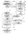
本発明の工業用内視鏡装置の一実施形態についての説明を、図面を参照しながら以下に行うが、本発明がこれらのみに限定解釈されるものでないことは勿論である。なお、図1は、本実施形態の工業用内視鏡装置の一実施形態を示す図であって、全体構成を示す斜視図である。また、図2は、同工業用内視鏡装置の制御部を中心とする内部構造を説明するためのブロック図である。また、図3は、同工業用内視鏡装置の同制御部の動作を説明するためのブロック図である。また、図4は、同工業用内視鏡装置の同制御部の制御動作を説明する図であって、被検査物内の検査を行う際の検査計画を立てるまでを示すフローチャート図である。また、図5は、同工業用内視鏡装置を用いた検査の流れを示すフローチャート図である。また、図6は、同工業用内視鏡装置の表示部である液晶モニタの画面を示す図である。また、図7(a)及び(b)は、同液晶モニタ上の要部を示す図であって、図6の表示領域A1を示す図である。また、図8は、同液晶モニタ上の同要部を示す図であって、図6の表示領域A1を切り替えた図である。また、図9は、同液晶モニタの表示画面を示す図である。また、図10は、同工業用内視鏡装置のリモートコントローラを示す側面図である。また、図11は、同工業用内視鏡装置の制御部によるマッチング動作を説明するための図であって、(a)が特徴抽出工程を説明する図であり、(b)が特徴比較を行っている状態を説明するための図である。また、図12は、同工業用内視鏡装置の同液晶モニタの画面を示す図であって、表示内容を切り替えた状態を示す図である。また、図13は、同工業用内視鏡装置の同制御部に保存される記録内容の一覧を説明する図である。また、図14は、同工業用内視鏡装置の同液晶モニタの画面を示す図であって、表示内容を切り替えた状態を示す図である。 An embodiment of the industrial endoscope apparatus of the present invention will be described below with reference to the drawings, but the present invention is of course not limited to these. FIG. 1 is a diagram showing an embodiment of the industrial endoscope apparatus of the present embodiment, and is a perspective view showing the overall configuration. FIG. 2 is a block diagram for explaining the internal structure centering on the control unit of the industrial endoscope apparatus. FIG. 3 is a block diagram for explaining the operation of the control unit of the industrial endoscope apparatus. FIG. 4 is a flowchart for explaining the control operation of the control unit of the industrial endoscope apparatus, and is a flowchart showing the process until an inspection plan is established for inspecting the inspected object. FIG. 5 is a flowchart showing the flow of inspection using the industrial endoscope apparatus. Moreover, FIG. 6 is a figure which shows the screen of the liquid crystal monitor which is a display part of the same industrial endoscope apparatus. FIGS. 7A and 7B are diagrams showing the main part on the liquid crystal monitor, and showing the display area A1 of FIG. FIG. 8 is a diagram showing the main part on the liquid crystal monitor, and is a diagram in which the display area A1 in FIG. 6 is switched. FIG. 9 is a view showing a display screen of the liquid crystal monitor. FIG. 10 is a side view showing a remote controller of the industrial endoscope apparatus. Moreover, FIG. 11 is a figure for demonstrating the matching operation | movement by the control part of the same industrial endoscope apparatus, (a) is a figure explaining a feature extraction process, (b) is a characteristic comparison. It is a figure for demonstrating the state currently performed. Moreover, FIG. 12 is a figure which shows the screen of the liquid crystal monitor of the same industrial endoscope apparatus, and is a figure which shows the state which switched the display content. FIG. 13 is a diagram for explaining a list of recorded contents stored in the control unit of the industrial endoscope apparatus. Moreover, FIG. 14 is a figure which shows the screen of the liquid crystal monitor of the industrial endoscope apparatus, and is a figure which shows the state which switched the display content.
まず、図1を参照して本実施形態の工業用内視鏡装置1のシステム構成を説明する。
図1に示すように、この工業用内視鏡装置1は、光学アダプタ2と、この光学アダプタ2が着脱自在に接続される内視鏡プローブ3を有する内視鏡4と、内視鏡4が収納されるコントロールユニット(本体)6と、各種動作制御を実行させるための操作を行うリモートコントローラ7と、内視鏡画像や操作制御内容(例えば処理メニュー)、さらにはナビゲーション情報等が表示される表示装置である液晶モニタ(以下、LCDと称する)8と、通常の内視鏡画像、あるいはその内視鏡画像をステレオ画像として立体視可能なフェイスマウントディスプレイ(以下、FMDと称する)9と、このFMD9に画像データを供給するFMDアダプタ9aとを備えて概略構成されている。
First, the system configuration of the
As shown in FIG. 1, this
前記内視鏡プローブ3は、その先端部3aにCCD(光学撮像素子。図示せず。)を内蔵した細長いケーブルであり、コントロールユニット6から引き出して被検査物(被観察物)内に挿入することが可能となっている。そして、この内視鏡プローブ3の先端部3aには、立体視観察用であるステレオ測定用の光学アダプタ2の他に、通常観察用の比較計測用光学アダプタ10も着脱自在に接続できるようになっている。
なお、同図の符号11は、後述のCCU17を経由せずに映像を映像信号処理回路に入力するための外部映像入力端子を示している。また、符号12は、外部から電力を取り入れるためのコンセントケーブルを示している。
The
Note that
続いて、図2を参照しながら工業用内視鏡装置1の内部構造の詳細説明を以下に行う。
同図に示すように、内視鏡プローブ3の基端部は、コントロールユニット6内の内視鏡ユニット15に接続されている。この内視鏡ユニット15の内部には、撮影時に必要な照明光を内視鏡プローブ3に内蔵されたライトガイドに供給する光源16や、内視鏡プローブ3に内蔵された湾曲部(図示せず)を電気的に湾曲動作させる電動湾曲装置(図示せず)などが内蔵されている。さらに、コントロールユニット6内には、内視鏡プローブ3の挿入長(すなわち、コントロールユニット6からの内視鏡プローブ3の引き出し長さ)を検出する内視鏡挿入長センサ(ロータリーエンコーダ)REが内蔵されている。
Next, a detailed description of the internal structure of the
As shown in the figure, the proximal end portion of the
内視鏡プローブ3の先端部3a内には、前記CCDが内蔵されており、このCCDから出力される撮像信号が、画像処理部であるカメラコントロールユニット(以下、CCUと称する)17に入力されるようになっている。このCCU17は、入力された撮像信号を例えばNTSC信号等の映像信号に変換して、コントロールユニット6内の制御部CUに供給するように構成されている。
The
コントロールユニット6内に搭載される前記制御部CUは、CPU18、ROM19、RAM20、PCカードインターフェイス(以下、PCカード I/Fと称する。)21a、USBインターフェイス(以下、USB I/Fと記載する。)21b、RS−232Cインターフェイス(以下、RS−232C I/Fと記載する。)21c、音声信号処理回路22、映像信号処理回路23、そして記録部Rを備えて構成されている。
The control unit CU mounted in the
前記CPU18は、主要プログラムに基づいて各種機能を実行/動作させる制御と、計測処理とを行うマイクロプロセッサーである。そして、このCPU18は、ROM19に格納されているプログラムを実行し、目的に応じた処理を行うことでシステム全体の動作制御を行うようになっている。
前記RS−232C I/F21cは、リモートコントローラ7による操作に基づいてコントロールユニット6全体を動作制御するのに必要な通信を行うためのインターフェイスであり、CCU17、内視鏡ユニット15、内視鏡挿入長センサRE、そしてリモートコントローラ7のそれぞれに接続されている。また、バスを介してCPU18に接続されている。これにより、リモートコントローラ7で、CCU17及び内視鏡ユニット15への動作指示及び制御を行うことが可能となっている。
The
The RS-232C I /
前記USB I/F21bは、コントロールユニット6とパーソナルコンピュータ25との間を電気的に接続するためのインターフェイスである。このUSB I/F21bを介してコントロールユニット6とパーソナルコンピュータ25を接続した場合に、パーソナルコンピュータ25側からも、リモートコントローラ7から動作指示した場合と同様に、内視鏡画像の表示指示や計測時における画像処理などの各種の制御指示をコントロールユニット6に対して行うことが可能となる。さらには、コントロールユニット6及びパーソナルコンピュータ25間での各種処理に必要な制御情報やデータ等の入出力も可能としている。
The USB I /
前記PCカード I/F21aには、PCMCIAメモリーカード26のみならず、PCMCIAカードアダプタを介してコンパクトフラッシュ(登録商標)メモリーカード27等の外部記憶媒体が着脱自在に装着されるようになっている。そして、この外部記憶媒体を装着した場合には、CPU18の制御により、これら外部記憶媒体に記憶された制御処理情報や検査記録等のデータを、PCカード I/F21aを介してコントロールユニット6内に取り込んだり、または、PCカード I/F21aを介して制御処理情報や検査記録等のデータを前記外部記憶媒体に供給して記録させることができるようになっている。
In addition to the
前記映像信号処理回路23は、CCU17から供給された内視鏡画像とグラフィック表示された操作メニューとを合成した合成画像を表示する機能を有しており、CCU17からの映像信号と、CPU18により生成された操作メニューの表示信号とを合成処理し、さらに、LCD8の画面上に表示するのに必要な処理を施してからLCD8に供給する。これにより、LCD8には、内視鏡画像と操作メニューとの合成画像が表示される。なお、映像信号処理回路23は、単に内視鏡画像、あるいは操作メニュー等の画像を単独で表示させるための処理を行うことも可能となっている。
前記LCD8は、内視鏡プローブ3からの内視鏡画像(映像)や操作制御内容(例えば処理メニュー)等の表示を行う表示部であるタッチパネル式の液晶モニタである。
The video
The
前記コントロールユニット6には、CCU17を経由せずに映像信号処理回路23に映像を入力する前記外部映像入力端子11が別に設けられている。この外部映像入力端子11に映像信号が入力された場合、映像信号処理回路23は、CCU17からの内視鏡画像に優先して前記映像信号に基づく合成画像を出力する。
The
前記音声信号処理回路22には、マイク28により集音されて前記外部記憶媒体に記録される音声信号や、前記外部記憶媒体の再生により得られる音声信号や、CPU18により生成された音声信号が供給されるようになっている。そして、この音声信号処理回路22は、供給された音声信号を再生するために必要な処理(増幅処理等)を施した後、スピーカ22aに出力する。これにより、スピーカ22aから音声信号が再生される。
前記リモートコントローラ7には、湾曲操作用のジョイスティック、メニュー選択用のジョイスティック、フリーズスイッチ、画像記録スイッチ等が設けられており、各種のリモコン操作を行えるようになっている。これについて図10を参照して説明すると、観察者の判断により、図10に示すリモートコントローラ7のフリーズスイッチ7aを押下することでLIVE画像を停止させ、画像記録スイッチ7bを押下することで、停止させたLIVE画像を制御部CUの記録部Rに記録することができるようになっている。ちなみに、この図10における符号7cは、内視鏡プローブ3の先端を湾曲動作させるためのジョイスティックであり、また符号7dは、LCD8上のポインタを動かすためのジョイスティックである。
The audio
The
ところで、前述したように、コントロールユニット6内には、装置全体の制御動作を司る制御部CUや、この制御部CUから発せられた音声ガイドを発するスピーカ22aなどが収容されており、本実施形態の工業用内視鏡装置1は、これらが有する機能により、観察者の検査作業をアシストするとともに、再現性のある検査結果の記録を行える点が特に特徴的となっている。
すなわち、制御部CUは、被検査物内の形状寸法を示す形状データを読み込み、この形状データ及びリアルタイム映像間の比較により、被検査物内における内視鏡プローブ3のヘッド(先端部3a)の位置及び姿勢を求めることが可能となっている。
By the way, as described above, the
That is, the control unit CU reads shape data indicating the shape dimensions in the inspection object, and compares the shape data and the real-time image to determine the head (
さらに、制御部CUは、このようにして求めた内視鏡プローブ3の位置及び姿勢を、LCD8に表示すると同時に、スピーカ22aから音声ガイドとして発することにより、観察者に、どのように内視鏡プローブ3を操作すればスムーズに検査が行えるかを常に指示することも可能としている。
また、制御部CUは、前記記録部Rを備えており、求めた内視鏡プローブ3の位置及び姿勢と、これら位置及び姿勢に対応する前記リアルタイム映像とを関連づけた検査記録を記録することも可能としている。記録部Rに記録したデータは、図示しないコピーメニューを実行することにより、PCカードI/F 21aを介してPCMCIAメモリーカード26などの外部記憶媒体に記録することができる。これにより、工業用内視鏡装置1で行った検査内容をPC(パーソナルコンピュータ)などで確認、又は保存することができる。
Further, the control unit CU displays the position and posture of the
In addition, the control unit CU includes the recording unit R, and records a test record in which the obtained position and posture of the
以下、この制御部CUの詳細について説明する。
この制御部CUでは、図3の紙面左下の符号a,bに示すように、被検査物内の内部形状を示す計算機モデル(3Dモデル)を構築し、この計算機モデルに基づいて挿入予定経路(ルート)を設定するようになっている。すなわち、制御部CUでは、これから検査を行う被検査物内の各検査箇所をどのような挿入予定経路を通って検査するかを予め決める検査計画を立てることができるようになっている。この詳細について、図4のフローチャートを参照しながら説明する。
Details of the control unit CU will be described below.
In this control unit CU, a computer model (3D model) indicating the internal shape of the object to be inspected is constructed as shown by reference symbols a and b in the lower left of the page of FIG. Root) is set. In other words, the control unit CU can make an inspection plan that determines in advance what kind of planned insertion path each inspection location in the inspection object to be inspected will be inspected. The details will be described with reference to the flowchart of FIG.
まず、検査計画設定を開始すると、ステップS1において、被検査物情報及び検査履歴情報の読み込みが実行される。この被検査物情報としては、例えば、被検査物の設計情報(CADデータ)が好適に用いられる。また、検査履歴情報としては、被検査物内の、過去に行った検査箇所の位置や、同位置で撮像された映像などの検査記録が読み込まれる。なお、設計情報の読み込みに際しては、この制御部CU内の記録部Rに保存しておいたものを使用しても良いし、または、通信回線を介して接続された他の計算機から読み込むものとしても良い。
続くステップS2では、被検査物情報として読み込まれた被検査物の設計情報に基づいて計算機モデル(3Dモデル、形状データ)が生成される。この計算機モデルの生成により、制御部CUは、被検査物の詳細かつ高精度な内部形状の把握を行う。
First, when inspection plan setting is started, reading of inspection object information and inspection history information is executed in step S1. As the inspection object information, for example, design information (CAD data) of the inspection object is preferably used. Further, as the inspection history information, the inspection record such as the position of the inspection place performed in the past in the inspection object and the video imaged at the same position is read. When reading design information, the design information stored in the recording unit R in the control unit CU may be used, or it may be read from another computer connected via a communication line. Also good.
In the subsequent step S2, a computer model (3D model, shape data) is generated based on the design information of the inspection object read as the inspection object information. By generating this computer model, the control unit CU grasps the detailed and highly accurate internal shape of the inspection object.
ステップS3では、生成された計算機モデルに基づくチャート図を、図6に示す表示画面の表示領域A1に表示させる。このチャート図は、例えば、被検査物の三面図(平面図、正面図、側面図)及び斜視図であり、これらの全てを一括表示したり、または、これらのうちの一図または複数図を選択して表示させることが可能となっている。
なお、これら図のうちのどれを表示領域A1に表示させるかは、図7(a),(b)に示す表示切り替え操作部a2内のどのボタンを押すかによって選択することが可能となっている。すなわち、表示切り替え操作部a2の「平」のボタンを押した場合には平面図が表示され、また、表示切り替え操作部a2の「正」のボタンを押した場合には正面図が表示され、また、表示切り替え操作部a2の「側」のボタンを押した場合には側面図が表示され、また、表示切り替え操作部a2の「斜」のボタンを押した場合には斜視図が表示される。各ボタンのうちのどれが選択されたかは、太枠表示されることによって確認することができる。
In step S3, a chart based on the generated computer model is displayed in the display area A1 of the display screen shown in FIG. This chart is, for example, a three-view drawing (plan view, front view, side view) and perspective view of an object to be inspected. It is possible to select and display.
It should be noted that which of these figures is displayed in the display area A1 can be selected depending on which button in the display switching operation unit a2 shown in FIGS. 7A and 7B is pressed. Yes. That is, when the “flat” button of the display switching operation unit a2 is pressed, a plan view is displayed, and when the “positive” button of the display switching operation unit a2 is pressed, a front view is displayed. Further, when the “side” button of the display switching operation unit a2 is pressed, a side view is displayed, and when the “slanting” button of the display switching operation unit a2 is pressed, a perspective view is displayed. . Which button is selected can be confirmed by being displayed in a thick frame.
この表示領域A1に表示されるチャート図は、後述の検査実施時において、被検査物内における自らの位置(内視鏡プローブ3の先端位置)を知るための地図の役目を有しており、その位置を指し示すマークが図中にリアルタイムで表示されるものとなっている。
図7(a),(b)に示すように、表示領域A1には、チャート図を拡大表示または縮小表示させるための表示倍率操作部a1が備えられている。そして、ここに表示される拡大/縮小倍率を上下させる(具体的には、表示倍率操作部a1の左にある虫眼鏡印を押すことによって縮小表示させたり、あるいは、表示倍率操作部a1の右にある虫眼鏡印を押すことによって拡大表示させる。)ことで、図7(a)に示すようにチャート図を縮小表示させて被検査物の全体像を把握したり、あるいは、図7(b)に示すように任意箇所(例えば、図7(a)のチャート図内のU部)を拡大表示させて被検査物内における内視鏡プローブ3の位置を正確に把握することが可能となっている。
The chart displayed in the display area A1 has a map function for knowing its own position (tip position of the endoscope probe 3) in the inspection object at the time of an inspection described later. A mark indicating the position is displayed in real time in the figure.
As shown in FIGS. 7A and 7B, the display area A1 is provided with a display magnification operation unit a1 for enlarging or reducing the chart. Then, the enlargement / reduction magnification displayed here is increased or decreased (specifically, the magnification is reduced by pressing the magnifying glass mark on the left of the display magnification operation unit a1, or is displayed on the right of the display magnification operation unit a1). By pressing a certain magnifying glass mark, an enlarged display is made.) As shown in FIG. 7 (a), the chart is reduced and the overall image of the inspection object is grasped, or in FIG. 7 (b). As shown, it is possible to enlarge and display an arbitrary portion (for example, U portion in the chart of FIG. 7A) to accurately grasp the position of the
このチャート図を用いて、被検査物内における自らの位置(内視鏡プローブ3の先端位置)を把握する具体的方法について説明すると、まず図7(a)において、被検査物全体における内視鏡プローブ3の位置を、同図の太矢印を確認することで把握する。なお、同図における符号APは、被検査物内に内視鏡プローブ3を挿入する際の挿入口(アクセスポイント)を示している。
With reference to this chart, a specific method for grasping its own position (tip position of the endoscope probe 3) in the inspection object will be described. First, in FIG. The position of the
続いて、被検査物内における内視鏡プローブ3の先端位置を詳細に把握すべく、表示倍率操作部a1を操作して図7(a)のU部を拡大表示させて図7(b)の表示内容にする。すると、内視鏡プローブ3の挿入経路が拡大表示されるとともに、この挿入経路上に後述のID番号が重ねて表示される。これらID番号は、内視鏡プローブ3の挿入順路を示しており、例えば同図の場合では、(1)−>(2)−>(3)−>(4)−>(5)−>(6)の順番に沿って内視鏡プローブ3を挿入していけば良いことを示している。さらに、同図における太線矢印が、内視鏡プローブ3の先端位置及びその向きを示している。したがって、この太線矢印がID番号(3)とID番号(4)との間の位置に有ることから、同位置に内視鏡プローブ3の先端位置が存在することが把握できる。
Subsequently, in order to grasp in detail the tip position of the
再び図4に戻り、前記ステップ3に続くステップS4以降の説明を行う。このステップS4では、内視鏡挿入条件情報の入力が実行される。
まず、サブルーチンSUBのステップS5では、内視鏡装置情報の入力または読み込みが実行される。すなわち、観察者の操作により、前記内視鏡プローブ3に装着される光学アダプタの種類、内視鏡プローブ3の径及び長さ、測定モード(通常測定モード、ステレオ測定モード等)などの入力、またはこれらの読み込みが行われる。
続くステップS6では、観察者の操作により、前記チャート図上における内視鏡プローブ3の挿入開始位置の入力が行われる。すなわち、図7(a)で図示したアクセスポイントAPを前記チャート図上に指定する。この指定は、前記チャート図上に図示しないポインタを重ね合わせて指定することで行われる。なお、挿入口(アクセスポイントAP)が小さくて指定しづらい場合には、必要に応じて前記表示倍率操作部a1を操作して、前記チャート図を拡大表示させてから行うのが好ましい。
Returning to FIG. 4 again, the description of step S4 and subsequent
First, in step S5 of the subroutine SUB, input or reading of endoscope apparatus information is executed. That is, by the operation of the observer, input of the type of the optical adapter attached to the
In the subsequent step S6, the insertion start position of the
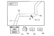
さらに続くステップS7では、前記チャート図上における検査部位と、これら検査部位に達する際に通るべき通過点との入力が行われる。この入力操作は、図7(b)に示した表示内容を、図8に示す「設定モード」に変更してから行われる。この「設定モード」では、画面下部に、これから設定するポイントが検査対象である「検査部位」であるのか、または、これら「検査部位」に到達するための道標となる「通過点」であるのかを選択する選択メニューm1と、同ポイントを他のポイントと識別したり、または、最終到達点であることを示すためのID番号を入力するID入力部m2と、各入力内容を決定するためのOKボタンm3と、各入力内容をキャンセルするCANCELボタンm4とが表示される。 In a further subsequent step S7, the inspection parts on the chart and the passing points to be passed when reaching these inspection parts are inputted. This input operation is performed after changing the display content shown in FIG. 7B to the “setting mode” shown in FIG. In this “setting mode”, at the bottom of the screen, whether the point to be set is the “inspection part” to be inspected, or the “passing point” that serves as a guide for reaching these “inspection part” A selection menu m1 for selecting the ID, an ID input unit m2 for identifying the same point as another point, or an ID number for indicating that it is the final destination, and for determining each input content An OK button m3 and a CANCEL button m4 for canceling each input content are displayed.
例えば、図8のID番号(3)に示す位置に検査部位を設定する場合には、同図に示すポインタを動かしてジョイスティックを押下して位置を決定する。続いて、選択メニューm1上に前記ポインタを重ね合わせて押下すると、「検査部位」及び「通過点」の両表示がプルダウンメニュー表示されるので、これらのうちの「検査部位」を選択して押下する。さらに続いて、前記ポインタを今度はID入力部m2上に重ね合わせ、▲印または▼印を押下することで、ID番号を入力する。なお、このID番号の入力操作は、観察者ではなく、前記制御部CU側が自動的に昇順に設定するようにしても良い。
以上の入力操作が正しく済んだらOKボタンm3を押下し、入力し直す場合にはCANCELボタンm4を押下する。OKボタンm3が押下された場合、前記制御部CUは、指定されたID番号が重複していないかをチェックし、重複していた場合には、再度入力を促すエラー表示を画面上に表示させる。重複せずに正しく入力された場合には、前記記録部Rに保存される。なお、ID入力部m2で「E」を選択した場合には、このポイントが最終到達点として設定保存される。
For example, when setting the examination site at the position indicated by the ID number (3) in FIG. 8, the pointer shown in FIG. 8 is moved and the joystick is pressed to determine the position. Subsequently, when the pointer is overlaid on the selection menu m1 and pressed, both the “test site” and “passing point” displays are displayed in a pull-down menu. To do. Subsequently, the pointer is superimposed on the ID input unit m2 and the ID number is input by pressing the ▲ or ▼ mark. The ID number input operation may be automatically set in ascending order by the control unit CU rather than the observer.
When the above input operation is correctly completed, the OK button m3 is pressed, and when re-inputting, the CANCEL button m4 is pressed. When the OK button m3 is pressed, the control unit CU checks whether the designated ID number is duplicated, and if it is duplicated, displays an error display prompting input again on the screen. . If it is correctly input without duplication, it is stored in the recording unit R. When “E” is selected in the ID input unit m2, this point is set and stored as the final destination.
最終到達点が入力されると、図8の画面が図9の画面に自動的に切り替わり、サブルーチンSUBにおける内視鏡挿入条件情報の入力が完了したか否かを問い合わせるステップS8が行われる。正しく完了している場合には、「Yes」ボタンを押下することで、サブルーチンSUBからメインルーチンの制御フローに戻る。一方、そうでない場合には、「No」ボタンを押下することで、再びステップS7に制御フローが戻される。
なお、上記各ステップS5〜S8の入力操作は、各入力項目が毎回同じである場合の入力操作の手間を省くべく、制御部CU内の記録部、または、前記PCMCIAメモリーカード26や前記コンパクトフラッシュ(登録商標)メモリーカード27等の外部記憶媒体に各入力項目を記録しておき、この記録内容を読み込ませることで、観察者の入力作業を省くものとしても良い。
When the final arrival point is input, the screen of FIG. 8 is automatically switched to the screen of FIG. 9, and step S8 for inquiring whether or not the input of the endoscope insertion condition information in the subroutine SUB is completed is performed. If it has been completed correctly, the control flow of the main routine is returned from the subroutine SUB by pressing the “Yes” button. On the other hand, if not, pressing the “No” button returns the control flow to step S7 again.
The input operations in the above steps S5 to S8 are performed in the recording unit in the control unit CU, the
メインルーチンのステップS9では、ステップS2で生成された計算機モデルと、ステップS4で入力された内視鏡挿入条件情報とに基づいて挿入予定経路情報の生成が行われる。すなわち、ステップS6で指定された挿入開始位置(アクセスポイントAP)から内視鏡プローブ3を挿入し、ステップS7で指定された各通過点を通って各検査部位に達するまでの最適な挿入予定経路が、制御部CUにより求められる。この挿入予定経路の設定は、全ての検査部位及び通過点を通ること、最短経路を通ること、内視鏡プローブ3の外径が通るのに狭すぎるような挿入箇所を避けること、などを判断基準として求められる。
そして、求められた挿入予定経路は、ステップS10において、前記チャート図上に重ねて表示される。これにより、地図であるチャート図上に、出発点である挿入開始位置(アクセスポイントAP)から、各通過点を通って各検査部位に達するまでの経路が確定される。
In step S9 of the main routine, planned insertion path information is generated based on the computer model generated in step S2 and the endoscope insertion condition information input in step S4. That is, the optimal planned insertion path until the
Then, the determined planned insertion path is displayed in an overlapping manner on the chart in step S10. As a result, the route from the insertion start position (access point AP), which is the starting point, to the inspection site through each passing point is determined on the chart as a map.
続くステップS11では、マーカー情報(VE情報)の生成が実行される(図3の符号c1も参照。)。すなわち、ステップS7で入力された各検査部位及び各通過点の、チャート図上における位置情報と、同位置に内視鏡プローブ3を配置して所定方向を向いたときの視線角度(姿勢情報)とが確定される。なお、ここで言う「VE」は「Virtual Endscope」の略であり、チャート図上に想定された仮想の内視鏡プローブを指し示すものとする。
In subsequent step S11, marker information (VE information) is generated (see also reference c1 in FIG. 3). That is, the position information on the chart diagram of each examination part and each passing point input in step S7, and the line-of-sight angle (posture information) when the
このようにして選び出されたマーカー情報(VE情報)に基づき、ステップS12ではマーカーデータ(VE画像)の生成が行われる(図3の符号c2も参照。)。すなわち、ステップS11で確定された位置情報及び視線角度に仮想の内視鏡プローブ3を配置し、そのときに見える内視鏡画像を、前記計算機モデルに基づいて生成する。
ところで、内視鏡プローブ3に装着する光学アダプタとして、プリズムを内蔵し、側面から入射した光を反射させて前記CCD上に結像するタイプの側視アダプタを用いる場合には、前記CCD上には左右反転した画像(鏡像)が結像される。この画像とカレントVE画像との間でマッチングを取ろうとしても、正常にマッチングすることができない。そこで、前述のステップS5において内視鏡装置情報を入力する際に、使用する光学アダプタが側視アダプタであるか否かを前記制御部CU側に取り込んでおき、本ステップS12における上記マーカーデータ(VE画像)の生成において、生成された各VE画像を最終的に左右反転させておくことが好ましい。もちろん、側視アダプタを用いない場合には、この画像反転動作は不要である。
同様に、使用する光学アダプタ毎に歪曲収差の特性も異なるので、前記ステップS5において予め読み込まれた歪曲収差のデータも、マーカーデータ(VE画像)の生成に反映される。すなわち、前記仮想の内視鏡プローブから見た内視鏡画像を生成する際に、前記歪曲収差に基づいて画像を歪ませることで、同等の歪曲収差をマーカーデータ(VE画像)に与える。
Based on the marker information (VE information) selected in this way, marker data (VE image) is generated in step S12 (see also symbol c2 in FIG. 3). That is, the
By the way, in the case of using a side adapter of a type that incorporates a prism and reflects light incident from the side surface to form an image on the CCD as an optical adapter to be attached to the
Similarly, since the distortion aberration characteristics are different for each optical adapter to be used, the distortion aberration data read in advance in step S5 is also reflected in the generation of the marker data (VE image). That is, when generating an endoscopic image viewed from the virtual endoscopic probe, the image is distorted based on the distortion aberration, thereby giving equivalent distortion aberration to the marker data (VE image).
このようにして生成された内視鏡画像(VE画像)は、挿入予定経路上に設定された各通過点及び各検査部位の位置における仮想の内視鏡画像(3Dコンピュータグラフィック画像)であり、ステップS13においてランドマークの表示が実行される。ここで言うランドマークとは、挿入予定経路上を進みながら検査を行う際に現在位置の確認を行うのに適した、被検査物内の特徴ポイントのことを指し示すものである。そして、これらランドマークは、図6に示すように、各検査部位及び各通過点のVE画像をサムネール表示(縮小配列表示)したものが表示領域A2に表示される。なお、同図では、明確に説明するために、図7(b)に示したID番号((1),(2),(3),・・・)に対応する番号を記している。
同時に、図4のステップS14において、各VE画像のうち、検査実施時に最初に通る点のものが制御部CU側で選び出され、この選び出されたVE画像が、図6の表示領域A3にカレントVE画像として表示される。
The endoscope image (VE image) generated in this way is a virtual endoscope image (3D computer graphic image) at the position of each passing point and each examination site set on the planned insertion path, In step S13, a landmark is displayed. The landmark mentioned here indicates a feature point in the inspection object suitable for confirming the current position when performing an inspection while proceeding on the planned insertion path. Then, as shown in FIG. 6, these landmarks are displayed in the display area A2 as thumbnails (reduced arrangement display) of the VE images of each examination site and each passing point. In the figure, for the sake of clarity, numbers corresponding to the ID numbers ((1), (2), (3),...) Shown in FIG.
At the same time, in step S14 in FIG. 4, among the VE images, the one that passes first at the time of performing the inspection is selected on the control unit CU side, and this selected VE image is displayed in the display area A3 in FIG. It is displayed as the current VE image.
そして、図4のステップS15では、制御部CU内において仮想の内視鏡プローブを挿入した場合の挿入シミュレーションが実行される。この時、VE画像の再生が挿入開始点から最終到達点に至るまで順次行われ、内視鏡プローブ3を無理なく最後まで挿入できるかが計算機モデル上で確認される。
Then, in step S15 in FIG. 4, an insertion simulation is performed when a virtual endoscope probe is inserted in the control unit CU. At this time, the reproduction of the VE image is sequentially performed from the insertion start point to the final arrival point, and it is confirmed on the computer model whether the
その結果、ステップS16において、被検査物内の突起物に内視鏡プローブ3が引っかかって挿入不可となったり、極度に狭い箇所を通ったり、または極度に内視鏡プローブ3を曲げないと通れないような箇所を通るなど、設定した挿入予定経路が不適切であると確認された場合には、ステップS4に戻って(必要に応じて、ステップS5の内視鏡装置情報の入力又は読み込み及びステップS6の挿入開始位置入力にて入力された内容を修正した上で)再度、挿入予定経路の設定が実施される。
逆に、設定した挿入予定経路で問題ないとステップS16で判断された場合には、ステップS17に進み、設定した挿入予定経路の保存が行われる。この時、併せて前記計算機モデル、チャート図、挿入開始位置、各検査部位、各通過点、前記VE画像、各ランドマークなど、後の検査実施に用いる情報も、制御部CUの記録部Rに保存される。
As a result, in step S16, the
Conversely, if it is determined in step S16 that there is no problem with the set planned insertion path, the process proceeds to step S17, where the set planned insertion path is saved. At this time, the computer model, the chart, the insertion start position, each inspection site, each passing point, the VE image, each landmark, and other information used for subsequent inspection are also stored in the recording unit R of the control unit CU. Saved.
以上説明の各工程を実行することにより、これから検査を行うための検査計画が立てられ、制御部CUの記録部Rに保存される。続いて、本実施形態の工業用内視鏡装置1を用いて、前記検査計画に基づいて実際に被検査物内の検査を行う方法の詳細について、以下に説明を行う。
本実施形態の工業用内視鏡装置1を用いた検査方法では、被検査物内のリアルタイム映像(映像)を内視鏡プローブ3で撮像する工程と、被観察物内の形状寸法を示す前記形状データを読み込む工程と、映像及び前記形状データ間の比較により、被検査物内における内視鏡プローブ3の先端位置及び姿勢の両方を求める工程とを有するものとなっている。なお、後述においても述べるが、映像及び前記形状データ間の比較により、被検査物内における内視鏡プローブ3の先端位置及び姿勢の両方を求める工程は、リアルタイムに行うことに限らず、検査後に行うものとしても良い。
By executing each process described above, an inspection plan for performing an inspection is made and stored in the recording unit R of the control unit CU. Next, details of a method for actually inspecting the inspection object based on the inspection plan using the
In the inspection method using the
まず、工業用内視鏡装置1を被検査物の挿入開始位置(アクセスポイントAP)近傍に配置して起動させる。この時の工業用内視鏡装置1では、前記光源16が起動して内視鏡プローブ3内のライトガイドに照明光を供給し、また、内視鏡プローブ3先端の前記CCDからのリアルタイム映像を制御部CU側に送信(図3の符号d参照。)し、図6の表示領域A4に示すLIVE画像としてLCD8に表示させる。さらに、工業用内視鏡装置1側に備えられている挿入長センサREで検知される、内視鏡プローブ3の挿入長が、制御部CU側に送信される状態になる(図3の符号xも参照。)。
一方、制御部CU側では、前記保存情報を読み込み、図4に示した情報(チャート図、チャート図上に設定された挿入予定経路、挿入予定経路上に設定されたチェックポイントである各ランドマーク画像など)を、LCD8上に表示可能な状態になる。このようにして、検査準備が整う。
First, the
On the other hand, on the control unit CU side, the stored information is read, and the information shown in FIG. 4 (chart diagram, planned insertion path set on the chart diagram, each landmark which is a checkpoint set on the planned insertion path) An image or the like) can be displayed on the
その後、制御部CU内では、図5のステップS21に示すようにランドマークオフセットの初期化が実行される。すなわち、検査計画時に求められた各ランドマーク画像のうち、内視鏡プローブ3が最初に通るものが選定される。そして、ステップS22において、選定されたランドマーク画像の表示が太枠付き表示(図6参照)される。これにより、全ランドマーク画像のうちのどれが現在選定されているかを観察者が一目で判るようにする。
続くステップS23では、選定されたランドマーク画像が図6に示すカレントVE画像として拡大表示される。なお、ここで言う「カレント」とは、「現在選択されている」という意味を示す。
Thereafter, in the control unit CU, initialization of the landmark offset is executed as shown in step S21 of FIG. In other words, among the landmark images obtained at the time of the inspection plan, the one that the
In the subsequent step S23, the selected landmark image is enlarged and displayed as a current VE image shown in FIG. Here, “current” means “currently selected”.
この状態で、観察者は、前記挿入開始点より内視鏡プローブ3を被検査物内に挿入していく。この時の内視鏡プローブ3の先端位置及び姿勢は、図7(b)で示したように、前記チャート図上の太矢印マークとして表示される。また、この時に撮像されるリアルタイム映像は、図6の表示領域A4にLIVE画像として表示される。また、同図6の表示領域A5に示す「テキスト支援情報」の箇所には、これから向かうランドマーク(次のランドマーク)までの距離、方向や、最終到達目標(最終のランドマーク)までの距離、方向、残ランドマーク数などの文字情報が表示される。観察者は、LCD8上のこれら文字情報及び各画像情報を見て前記リモートコントローラ7を操作しながら、内視鏡プローブ3の挿入を進めていく。
なお、以下の説明においては、制御部CU内の処理動作を中心に説明を行うが、観察者は、内視鏡プローブ3の挿入を、LCD8を介して制御部CUから送られてくる指示に従って進めながらLIVE画像を観察することで被検査物の内部検査を適宜実施する。
In this state, the observer inserts the
In the following description, the processing operation in the control unit CU will be mainly described. However, the observer follows the instruction sent from the control unit CU via the
続いて、内視鏡プローブ3の先端位置がカレントVE画像の位置(目標として選定されたランドマーク位置)に到達したと「判断」すると、図3に示す符号e,f(符号kについては後述で説明する。)及び図5に示すステップS24において、特徴抽出の作業が開始される。なお、上記「判断」を制御部CUに行わせる方法としては、以下に説明する2通りがある。
第1の判断方法は、観察者が、見ているLIVE画像の映像がカレントVE画像に似たような場所に近づいてきたと自ら判断した場合に、リモートコントローラ7を操作して制御部CUに知らせる方法である。
Subsequently, when it is “determined” that the tip position of the
The first determination method is to notify the control unit CU by operating the
第2の判断方法は、LIVE画像とカレントVE画像とのマッチング動作を常時行っている場合(すなわち、上記第1の判断方法の場合のように、挿入予定経路上の所定ポイントにおいてのみマッチング動作を行うのではなく、挿入予定経路を進んでいく際に刻々と変わる「道」の映像に対してマッチング動作を連続して行う場合。)である。この場合には、観察者が判断するのではなく、マッチング動作を連続して行う制御部CUが、LIVE画像にマッチングさせたカレントVE画像が、「目標とするランドマーク位置」のものである場合に、「目標とするランドマーク位置に到達した」と自動的に判断する。この第2の判断方法を適用した場合には、後述のステップS30は不要となるが、これについては、後述で説明する。 In the second determination method, when the matching operation between the LIVE image and the current VE image is constantly performed (that is, as in the case of the first determination method, the matching operation is performed only at a predetermined point on the planned insertion path. This is a case where the matching operation is continuously performed on the video of the “road” that changes every moment when the route is to be inserted instead of being performed. In this case, the current VE image matched with the LIVE image by the control unit CU that continuously performs the matching operation is not “judged by the observer”, but the “target landmark position”. Then, it is automatically determined that “the target landmark position has been reached”. When this second determination method is applied, step S30 described later is unnecessary, but this will be described later.
以上のようにして「目標とするランドマーク位置に到達した」と制御部CUが判断した後の特徴抽出では、図6に示すLIVE画像上の特徴点(稜線形状、突起形状、孔形状、文字情報など。画像上の輝度分布によりこれら形状を判別することで特徴点を抽出する。)と、カレントVE画像上の特徴点(ワイヤーフレームとして表示される稜線形状、突起形状、孔形状、文字情報など。)とがそれぞれ抽出される。 In the feature extraction after the control unit CU determines that “the target landmark position has been reached” as described above, the feature points (ridge line shape, protrusion shape, hole shape, character on the LIVE image shown in FIG. 6 are used. Information, etc. Feature points are extracted by discriminating these shapes based on the luminance distribution on the image.) And feature points on the current VE image (ridge line shape, projection shape, hole shape, character information displayed as a wire frame) Etc.) are extracted.
これについて、図11(a)を用いて具体的に説明する。まず、LIVE画像上から、輝度が極端に変わる線をつなげていくことで、図11(a)の左図に示すように、LIVE画像上に映し出された部品の特徴をなす外形状が、ワイヤーフレームに変換して表示される。一方、カレントVE画像上における同部品は、既にワイヤーフレーム(同図右側)で表されているので、このワイヤーフレームを、部品外形を示す特徴点としてそのまま用いることができる。
なお、本実施形態では、カレントVE画像を設計データに基づいて作成しているが、これに限らず、過去検査時に撮影した実映像に基づいて作成することも可能である。その場合には、図11(a)でカレントVE画像から特徴点を抽出した手順と同様の手順により、特徴点の抽出を行うことで対応できる。すなわち、過去検査時の実映像上から、輝度が極端に変わる線をつなげていくことで、過去検査時の実映像上に映し出された部品の特徴をなす外形状が、ワイヤーフレームに変換して表示される。
This will be specifically described with reference to FIG. First, as shown in the left diagram of FIG. 11 (a), by connecting a line whose luminance changes extremely from the LIVE image, the outer shape that characterizes the component displayed on the LIVE image is a wire. It is converted into a frame and displayed. On the other hand, since the part on the current VE image is already represented by a wire frame (right side in the figure), the wire frame can be used as it is as a feature point indicating the part outline.
In the present embodiment, the current VE image is created based on the design data. However, the present invention is not limited to this, and the current VE image can also be created based on the actual video shot at the past examination. In such a case, it can be dealt with by extracting the feature points by the same procedure as the procedure for extracting the feature points from the current VE image in FIG. In other words, by connecting a line whose brightness changes extremely from the actual image at the time of past inspection, the outer shape that characterizes the part displayed on the actual image at the time of past inspection is converted into a wire frame. Is displayed.
そして、このようにして求められた両画像の特徴点が、図3の符号g及び図5のステップS25に示す工程において比較される。すなわち、ステップS25では、図11(b)に示すように、LIVE画像のワイヤーフレームとカレントVE画像のワイヤーフレームとを互いに重ね合わることで特徴比較が行われる。 Then, the feature points of the two images obtained in this way are compared in the process indicated by reference sign g in FIG. 3 and step S25 in FIG. That is, in step S25, as shown in FIG. 11B, feature comparison is performed by superimposing the wire frame of the LIVE image and the wire frame of the current VE image on each other.
そして、両画像の特徴点が一致(マッチング)するかどうかが図5のステップS26において判定され、一致した場合(Yesの場合)にはステップS29へと進み、一方、一致しなかった場合(Noの場合)にはステップS27へと進む。
ステップS27に進んだ場合には、両画像の相対的な位置関係がずれている場合が想定されるとして、内視鏡プローブ3の先端の位置姿勢推定が実行される(図3の符号i,jも参照。)。すなわち、制御部CUは、カレントVE画像の表示内容がLIVE画像と一致するように仮想内視鏡プローブの位置及び姿勢を変更した場合の位置移動量及び姿勢移動量を算出し、これらを、検査計画時にこのカレントVE画像を作成したと同時に記録した仮想内視鏡プローブの位置及び姿勢に加えることで、現在の内視鏡プローブ3の先端の位置及び姿勢を推定して求める。
Then, whether or not the feature points of both images match (matching) is determined in step S26 in FIG. 5. If they match (Yes), the process proceeds to step S29, whereas if they do not match (No) In the case of), the process proceeds to step S27.
When the process proceeds to step S27, it is assumed that the relative positional relationship between the two images is deviated, and the position / posture estimation of the tip of the
前記ステップS27に続くステップS28では、LIVE画像に対してカレントVE画像の位置及び姿勢(画像の上下向きを含む)を一致させるべく、カレントVE画像側の加工表示を行う(図3の符号kも参照。)。すなわち、制御部CUは、ステップS27において求められた現在の内視鏡プローブ3の位置及び姿勢を参照し、これと一致するようにカレントVE画像の位置及び姿勢を変更する。この変更に伴い、カレントVE画像の表示内容が回転、上下移動、左右移動、拡大、縮小するなどして、LIVE画像の表示内容と一致する。
In step S28 following step S27, processing and display on the current VE image side is performed in order to match the position and orientation of the current VE image (including the vertical direction of the image) with respect to the LIVE image (reference symbol k in FIG. 3 also). reference.). That is, the control unit CU refers to the current position and posture of the
このようにして表示内容が一致した後のカレントVE画像上には、さらに内視鏡プローブ3を挿入するための挿入方向を指し示す矢印等の操作指示が表示される(図3の符号m,nも参照。)。すなわち、制御部CUは、求めた内視鏡プローブ3の位置及び姿勢と挿入予定経路との比較に基づき、この内視鏡プローブ3の移動すべき方向を求めて図3のnに示すようにカレントVE画像上に矢印を表示する。この時、必要に応じて前記スピーカ22aからも、音声による操作指示(「上に進んでください」、「右に進んでください」等)を行う。
そして、ステップS28において表示内容が一致した後の制御流れは、再びステップS24へと戻され、再び特徴抽出の工程が実行される。このようにして、LIVE画像の特徴とカレントVE画像の特徴とが一致してステップS29に向かうまで、ステップS24〜ステップ28の工程が繰り返される。
On the current VE image after the display contents match in this way, an operation instruction such as an arrow indicating the insertion direction for inserting the
Then, the control flow after the display contents match in step S28 is returned again to step S24, and the feature extraction process is executed again. In this way, steps S24 to 28 are repeated until the features of the LIVE image match the features of the current VE image and the process proceeds to step S29.
このようにして、現時点において見えている場所の特定がなされ、検査部位に到達した時点で、制御部CUは、LCD8上の表示画面を図6の表示内容から図12の表示内容に自動的に切り替え、「検査モード」に移る。
図12に示すように、画面中央下部に示す表示領域A6には、検査項目のリストが一覧表示される。この検査項目のリストは、このランドマーク位置の検査箇所において検査すべき項目の見出しを一覧表示したものである。これら検査項目のリストのうちの何れかを観察者が選択すると、左側の表示領域A7に、検査項目の詳細が表示される。さらに、図12の中央上部の「参考画像」の表示A8を観察者が押すと、過去に撮影した同箇所の画像(過去画像)が記録部Rから読み出され、左側の表示領域A9に表示される。なお、表示A8を省略し、表示A6を押して表示領域A7に検査項目の詳細を表示させた時点で、自動的に表示領域A9に過去画像を表示させるように構成しても良い。
In this way, the location visible at the present time is specified, and when the examination site is reached, the control unit CU automatically changes the display screen on the
As shown in FIG. 12, a list of inspection items is displayed in a list in the display area A6 shown at the lower center of the screen. This list of inspection items is a list of headings of items to be inspected at the inspection location at the landmark position. When the observer selects one of these inspection item lists, the details of the inspection item are displayed in the left display area A7. Further, when the observer presses the “reference image” display A8 in the upper center of FIG. 12, the image of the same part (past image) taken in the past is read from the recording unit R and displayed in the display area A9 on the left side. Is done. The display A8 may be omitted, and the past image may be automatically displayed in the display area A9 when the details of the inspection item are displayed in the display area A7 by pressing the display A6.
観察者は、表示領域A7,A9に表示される情報を参考にして検査を行う。この検査においてキズ計測を行う場合には、図12の中央上部の表示A10を押下して「キズ計測モード」にすることで測定を実施する。
この検査部位における全ての検査が終了した場合には、観察者が図12の中央上部の「確認済」の表示A11を押す。すると、表示領域A6内に「済」のマークA61が表示されると同時に、検査が済んだことが制御部CUの記録部Rに証拠記録として保存される(図3の符号lも参照。)。このようにして制御部CUに検査記録を残すことにより、検査漏れをなくすことができる上に、後の解析に利用することが可能となる。なお、この記録動作は本例のように各ランドマーク通過後に逐一行っても良いし、もしくは、後述のステップS33に説明するように、最終ランドマークを通過後に一括して保存するものとしても良い。
The observer performs an inspection with reference to information displayed in the display areas A7 and A9. When scratch measurement is performed in this inspection, the measurement is performed by pressing the display A10 at the upper center of FIG. 12 to enter the “scratch measurement mode”.
When all examinations at this examination site are completed, the observer presses the “confirmed” display A11 at the upper center of FIG. Then, at the same time as the “completed” mark A61 is displayed in the display area A6, the fact that the inspection has been completed is stored in the recording unit R of the control unit CU as an evidence record (see also reference numeral 1 in FIG. 3). . By leaving the inspection record in the control unit CU in this way, it is possible to eliminate the inspection omission and to use it for later analysis. This recording operation may be performed one after another after passing through each landmark as in this example, or may be collectively stored after passing through the final landmark, as will be described later in step S33. .
制御部CUの記録部Rに保存される全記録項目の例を、図13に示す。
同図に示すように、記録部Rには、各ランドマークIDと、カレントVE画像の元となる被検査物全体の3Dモデルである検査部位モデルと、図4のステップS6において入力した内視鏡装置情報と、内視鏡プローブ3をどのような経路で挿入していったか(どの位置をどのような姿勢で通過させたか)を示す挿入軌跡情報と、前記検査対象物(エンジン、パイプなど)を識別するためのユニークなIDである被検体IDとが記録される。前記挿入軌跡情報の記録が、図5のステップS29に示す挿入軌跡情報更新である。挿入軌跡情報は、ランドマークIDと関連づけて記録されている。すなわち、ランドマーク地点各々での、位置・姿勢が関連づけて記録されている。
An example of all recorded items stored in the recording unit R of the control unit CU is shown in FIG.
As shown in the figure, in the recording unit R, each landmark ID, an examination part model that is a 3D model of the entire object to be inspected from which the current VE image is generated, and the endoscope input in step S6 in FIG. Mirror apparatus information, insertion path information indicating which path the
図13に示すように、各ランドマークIDの記録においては、このランドマークが「通過点」であるのか「検査部位」であるのかを示す識別情報も併せて保存される。そして、「通過点」の識別情報が付与されたランドマークには、この通過点をなすランドマーク位置に対応するVE画像が併せて保存される。一方、「検査部位」の識別情報が付与されたランドマークには、同ランドマーク位置に対応するVE画像に加えて、検査項目毎に取得した過去の画像(実画像)が併せて保存される。
以上のようにして全ての検査項目の実施が済んだ後は、LCD8の表示画面を、図12の表示内容(「検査モード」)から図6の表示内容に自動的に切り替える。
As shown in FIG. 13, in the recording of each landmark ID, identification information indicating whether the landmark is a “passing point” or an “inspection site” is also stored. Then, a VE image corresponding to the landmark position that forms the passing point is stored together with the landmark to which the identification information of “passing point” is given. On the other hand, in the landmark to which the identification information of “inspection site” is given, in addition to the VE image corresponding to the landmark position, a past image (actual image) acquired for each inspection item is also stored. .
After all the inspection items have been performed as described above, the display screen of the
上記ステップS29に続くステップS30においては、図14に示すように、液晶ディスプレイ8上に、ランドマークオフセットの更新を行うか否かを観察者に問い合わせる表示が示される。そして、観察者が、もうしばらく現在の観察部位に止まって観察を継続して行いたいなどの理由により、図14の「No」ボタンを押下すると、制御流れが図5のステップS24に戻される。そして、次のランドマーク位置に向かわずに観察を継続して行うことが可能となる。逆に、観察者が次のランドマーク位置に向かうことを決め、図14の「Yes」ボタンを押下すると、図5のステップS31に進む。
In step S30 following step S29, as shown in FIG. 14, a display asking the observer whether or not to update the landmark offset is displayed on the
ステップS31では、現在のランドマーク位置が最終のランドマーク位置であるかが制御部CUによって判定される。そして、最終のランドマーク位置に達していない(No)と判断された場合には、ステップS32へと進み、ランドマークオフセットの更新が実行される。すなわち、検査計画において求められた各ランドマーク画像のうち、次に内視鏡プローブ3が向かうもの(次に大きいID番号を有するVE画像)が新たな目標として選定される。
一方、ステップS31において最終のランドマーク位置に達している(Yes)と判断された場合には、ステップS33へと進み、全てのLIVE画像や、これらLIVE画像に対応して求められた内視鏡プローブ3の先端の位置及び姿勢など、図13で説明した事項が最終的な検査記録(観察記録)として制御部CU内の記録部Rに自動的に保存される。
以上により、検査実施時における前記制御部の制御動作が完了する。
In step S31, the control unit CU determines whether the current landmark position is the final landmark position. If it is determined that the final landmark position has not been reached (No), the process proceeds to step S32, and the landmark offset is updated. That is, among the landmark images obtained in the inspection plan, the next image to which the
On the other hand, if it is determined in step S31 that the final landmark position has been reached (Yes), the process proceeds to step S33, and all the LIVE images and endoscopes obtained corresponding to these LIVE images are displayed. The items described in FIG. 13 such as the position and orientation of the tip of the
Thus, the control operation of the control unit at the time of performing the inspection is completed.
以上説明のように、本実施形態の工業用内視鏡装置1によれば、その制御部CUが、被検査物内を検査している際のLIVE画像とカレントVE画像とを比較することにより、両者の相対関係を一致させることができる。これにより、現在観察を行っているLIVE画像を得るための内視鏡プローブ3の位置及び姿勢がどのようなものであるかを、計算機モデル上における内視鏡プローブ3の位置及び姿勢として求めることができる。しかも、計算機モデルは設計データに基づいているものであるため、被検査物内における内視鏡プローブ3の位置及び姿勢を正確かつ容易に求めることができる。
また、LIVE画像に基づく現在観察位置の判別を観察者が行うのではなく、制御部CU側で行うものであるため、検査すべき箇所を客観的に確認することができ、これにより、検査箇所を見逃す虞を低減させることができるようになる。
したがって、被検査物内における内視鏡プローブ3自らの位置及び姿勢を見失うことなく、かつ客観的に把握することができる。これにより、検査部位に容易に達することができ、なおかつ、検査結果を客観的記録として残すことが可能となる。
As described above, according to the
In addition, since the observer does not determine the current observation position based on the LIVE image but on the control unit CU side, it is possible to objectively confirm the location to be inspected. It is possible to reduce the risk of overlooking.
Therefore, the
また、本実施形態の工業用内視鏡装置1は、制御部CUが、前記チャート図上に設定される挿入予定経路をLCD8上に表示させる構成を採用した。
この構成によればLCD8上に表示される挿入予定経路に沿って各検査箇所の検査を行うことで、全ての検査箇所を見逃すことなく順番に検査できるようになる。したがって、熟練していない観察者であっても、熟練した観察者が行うように全ての検査箇所を見逃すことなく順番に観察することが可能となる。
Moreover, the
According to this configuration, by inspecting each inspection location along the planned insertion path displayed on the
また、本実施形態の工業用内視鏡装置1は、制御部CUが、挿入予定経路上に設定されたランドマーク画像をLCD8に表示させる構成を採用した。
この構成によれば、各ランドマーク位置を通ったか否かをLCD8上で確認しながら検査を行うことで、挿入予定経路上における全ての検査箇所を逃さず検査したかをより確実に確認することが可能となる。また、全ての検査箇所のうちのどこまで検査できたかを確認しながら検査を行うことも可能となっている。
Further, the
According to this configuration, by checking on the
また、本実施形態の工業用内視鏡装置1は、制御部CUが、求められた内視鏡プローブ3の位置及び姿勢と挿入予定経路との比較に基づき、この内視鏡プローブ3の移動すべき方向を求めて、観察者に指示する構成を採用した。
この構成によれば、制御部CUから発せられる指示(ナビゲーションガイド情報)に従って内視鏡プローブ3を操作しながら移動させることにより、挿入予定経路から外れることなく内視鏡プローブ3を移動させることができる。したがって、制御部CUからの指示に従って内視鏡プローブ3を移動させていくことで、あたかも熟練者が操作した場合のように、挿入予定経路から外れることなく内視鏡プローブ3を移動させることが可能となる。
Further, in the
According to this configuration, the
また、本実施形態の工業用内視鏡装置1は、制御部CUが、被検査物内における内視鏡プローブ3の位置及び姿勢と、これら位置及び姿勢に対応するLIVE画像とを関連づけた検査記録を自動的に記録する構成を採用した。この構成によれば、検査結果を、検査記録という客観的な記録として保存することができる。これにより、観察すべき部位を間違いなく観察したかどうかを第三者が客観的に確認することが可能となる。
Further, in the
なお、本実施形態においては、検査計画時のステップS3において作成されるチャート図(形状データ)が、被観察物の設計情報に基づいて構成された計算機モデルである場合を例に説明したが、これに限らず、以前検査した時の前記検査記録に記録された内視鏡プローブ3の位置及び姿勢と実映像とに基づいて計算機モデルを構成し、これをチャート図として採用しても良い。
すなわち、以前検査した際の実映像から特徴抽出を行ってコンピュータグラフィック化し、このコンピュータグラフィック画像と今回検査時の実映像とをマッチングさせることにより、現時点における内視鏡プローブ3の先端の位置及び姿勢を求めるようにしても良い。この場合、被検査物の設計データが不要となるので、より広い用途に柔軟に対応することが可能となる。
In the present embodiment, the chart diagram (shape data) created in step S3 at the time of the inspection plan is described as an example when the computer model is configured based on the design information of the object to be observed. However, the present invention is not limited to this, and a computer model may be configured based on the position and orientation of the
That is, feature extraction is performed from the actual video image obtained at the time of previous inspection, computerized, and this computer graphic image is matched with the actual video image at the time of the current inspection, so that the position and orientation of the distal end of the
また、本実施形態では、挿入予定経路上の各ランドマーク位置においてのみ(各チェックポイントにおいてのみ)、LIVE画像とカレントVE画像とのマッチングを行って内視鏡プローブ3の位置及び姿勢を求めるものとしたが、これに限らず、前述したように、常時マッチングを取るようにする構成も採用可能である。
すなわち、図4に示した検査計画時においては、挿入開始点から最終到達点に至るまでの全経路のVE画像(仮想内視鏡の視線から見たコンピュータグラフィック画像)を作成しておき、図5に示した検査実施時においては、前記全経路のVE画像とLIVE画像(リアルタイム映像)との間で常に特徴点のマッチングを取得し、これにより、内視鏡プローブ3の先端の位置及び姿勢を常時連続して求める。すなわち、図5のステップS30では何もせずに通過し、ステップS31におけるチェックのみを行う。
この場合、常時連続して求められる内視鏡プローブ3の位置及び姿勢に基づき、挿入予定経路に正しく沿って進むことができるように、前記操作指示(カレントVE画像上の矢印による指示や音声指示など。)も併せて発することにより、より高精度かつスムーズに観察者が内視鏡プローブ3を操作することが可能となる。したがって、より高い再現性を得ることが可能となる。
Further, in the present embodiment, the position and orientation of the
That is, at the time of the inspection plan shown in FIG. 4, a VE image (computer graphic image viewed from the virtual endoscope's line of sight) of all paths from the insertion start point to the final arrival point is created in advance. When the inspection shown in FIG. 5 is performed, matching of feature points is always acquired between the VE image and the LIVE image (real-time video) of the entire path, and thereby the position and orientation of the tip of the
In this case, based on the position and orientation of the
また、VE画像の生成に際しては、前記内視鏡挿入長センサREと、内視鏡プローブ3の先端に設けた角度センサ(図示せず)とを用いて、内視鏡挿入中における内視鏡プローブ3の先端の位置及び姿勢を推定し、この位置及び姿勢で得られる予定の画像をコンピュータグラフィックとして生成するものとしても良い。
Further, when generating the VE image, the endoscope during insertion of the endoscope is used by using the endoscope insertion length sensor RE and an angle sensor (not shown) provided at the tip of the
また、本実施形態では、LCD8上にLIVE画像とカレントVE画像を独立表示するものとしたが、これに限らず、カレントVE画像がワイヤーフレームである場合、これをLIVE画像に重畳して表示するものとしても良い。この場合、カレントVE画像側の表示領域を省略してLIVE画像側の表示領域を広く取る事が可能となる。一方、カレントVE画像がテクスチャを有する三次元画像である場合には、これを重畳してしまうとLIVE画像が見にくくなるので、本実施形態のように個別に分けて表示するのが好ましい。
In the present embodiment, the LIVE image and the current VE image are displayed independently on the
また、本実施形態では、被検査物内を検査する際に得られるリアルタイムの映像を、「その場で」形状データと比較することにより、内視鏡プローブ3の先端の位置及び姿勢を求めるものとしたが、これに限らず、検査後(観察後)に両者のマッチングを行うものとしても良い。すなわち、被検査物内の映像を撮像して検査を終え、その後、撮像した映像を前記形状データと比較する(マッチングする)ことで、内視鏡プローブ3の位置及び姿勢を検査後に求めるものとしても良い。
また、本実施形態では、内視鏡画像と形状データを比較し、内視鏡プローブの位置及び姿勢の少なくとも一方を求めることをコントロールユニット内に設けた制御部CUで行うようにしたが、制御部CUをPC25内に設けて行うものとしても良い。
In the present embodiment, the position and orientation of the tip of the
In this embodiment, the endoscope image and the shape data are compared, and at least one of the position and orientation of the endoscope probe is obtained by the control unit CU provided in the control unit. The unit CU may be provided in the
1・・・工業用内視鏡装置
3・・・内視鏡プローブ
8・・・LCD(表示部)
CU・・・制御部
DESCRIPTION OF
CU ... Control unit
Claims (10)
前記内視鏡プローブの通過点であるか検査部位であるかを示す識別情報を含む、前記被観察物におけるランドマークが記録されており、前記内視鏡プローブの先端部が前記ランドマークに到達し、前記識別情報が前記検査部位を示しているとき、前記表示部に前記ランドマークにおける検査項目が表示されるように制御する制御部を備えたことを特徴とする工業用内視鏡装置。 In an industrial endoscope apparatus comprising an endoscopic probe inserted into an object to be observed and a display unit for displaying an image captured by the endoscopic probe,
A landmark on the object to be observed including identification information indicating whether it is a passing point or an inspection site of the endoscope probe is recorded, and a distal end portion of the endoscope probe reaches the landmark An industrial endoscope apparatus comprising: a control unit that controls the display unit to display the inspection item in the landmark when the identification information indicates the inspection site .
前記制御部は、前記ランドマークにおける検査が終了したときに、検査が終了したことを示す情報を前記表示部に表示させることを特徴とする工業用内視鏡装置。The industrial endoscope apparatus, wherein when the inspection at the landmark is completed, the control unit displays information indicating that the inspection is completed on the display unit.
前記制御部は、前記ランドマークにおける前記検査項目ごとに取得された画像を記録することを特徴とする工業用内視鏡装置。The industrial endoscope apparatus, wherein the control unit records an image acquired for each inspection item in the landmark.
前記制御部は、前記映像を、前記被観察物内の形状寸法を示す形状データと比較することにより、前記被観察物内における前記内視鏡プローブの位置及び姿勢の少なくとも一方を求めることを特徴とする工業用内視鏡装置。The control unit obtains at least one of a position and a posture of the endoscope probe in the observation object by comparing the image with shape data indicating a shape dimension in the observation object. An industrial endoscope device.
前記内視鏡プローブの位置情報及び姿勢情報の少なくとも一方を前記表示部に表示させることを特徴とする工業用内視鏡装置。An industrial endoscope apparatus, wherein at least one of position information and posture information of the endoscope probe is displayed on the display unit.
前記制御部は、前記内視鏡プローブの挿入予定経路を前記表示部に表示させることを特徴とする工業用内視鏡装置。The industrial endoscope apparatus, wherein the control unit causes the display unit to display a planned insertion path of the endoscope probe.
前記制御部が、前記内視鏡プローブの位置情報及び姿勢情報の少なくとも一方と前記挿入予定経路との比較に基づき、該内視鏡プローブの移動すべき方向を前記表示部に表示することを特徴とする工業用内視鏡装置。The control unit displays a direction in which the endoscope probe should move on the display unit based on a comparison between at least one of position information and posture information of the endoscope probe and the planned insertion path. An industrial endoscope device.
前記制御部が、前記被観察物内において前記内視鏡プローブが取得した画像と、前記画像を取得したときの前記内視鏡プローブの位置情報及び姿勢情報の少なくとも一方とを関連づけて記録することを特徴とする工業用内視鏡装置。The control unit records an image acquired by the endoscope probe in the observation object in association with at least one of position information and posture information of the endoscope probe when the image is acquired. An industrial endoscope apparatus characterized by the above.
前記形状データが、前記内視鏡プローブが過去観察時に取得した画像と、前記画像を取得したときの前記内視鏡プローブの位置情報及び姿勢情報の少なくとも一方とに基づいて構成されたことを特徴とする工業用内視鏡装置。 The industrial endoscope apparatus according to any one of claims 4 to 8,
The shape data is configured based on an image acquired by the endoscope probe during past observation and at least one of position information and posture information of the endoscope probe when the image is acquired. An industrial endoscope device.
前記形状データが、前記被観察物の設計情報に基づいて構成されたことを特徴とする工業用内視鏡装置。An industrial endoscope apparatus, wherein the shape data is configured based on design information of the object to be observed.
Priority Applications (1)
| Application Number | Priority Date | Filing Date | Title |
|---|---|---|---|
| JP2003308944A JP4464640B2 (en) | 2003-09-01 | 2003-09-01 | Industrial endoscope equipment |
Applications Claiming Priority (1)
| Application Number | Priority Date | Filing Date | Title |
|---|---|---|---|
| JP2003308944A JP4464640B2 (en) | 2003-09-01 | 2003-09-01 | Industrial endoscope equipment |
Publications (3)
| Publication Number | Publication Date |
|---|---|
| JP2005077831A JP2005077831A (en) | 2005-03-24 |
| JP2005077831A5 JP2005077831A5 (en) | 2006-10-12 |
| JP4464640B2 true JP4464640B2 (en) | 2010-05-19 |
Family
ID=34411255
Family Applications (1)
| Application Number | Title | Priority Date | Filing Date |
|---|---|---|---|
| JP2003308944A Expired - Fee Related JP4464640B2 (en) | 2003-09-01 | 2003-09-01 | Industrial endoscope equipment |
Country Status (1)
| Country | Link |
|---|---|
| JP (1) | JP4464640B2 (en) |
Families Citing this family (4)
| Publication number | Priority date | Publication date | Assignee | Title |
|---|---|---|---|---|
| JP5525727B2 (en) * | 2005-05-23 | 2014-06-18 | ザ ペン ステイト リサーチ ファンデーション | 3D-CT registration with guidance method based on 3D-2D pose estimation and application to raw bronchoscopy |
| US20110184238A1 (en) * | 2010-01-28 | 2011-07-28 | The Penn State Research Foundation | Image-based global registration system and method applicable to bronchoscopy guidance |
| CN105100682B (en) * | 2014-04-30 | 2018-12-25 | 通用电气公司 | Borescope with navigation feature |
| WO2023218523A1 (en) * | 2022-05-10 | 2023-11-16 | オリンパス株式会社 | Second endoscopic system, first endoscopic system, and endoscopic inspection method |
Family Cites Families (4)
| Publication number | Priority date | Publication date | Assignee | Title |
|---|---|---|---|---|
| JPH11197159A (en) * | 1998-01-13 | 1999-07-27 | Hitachi Ltd | Operation supporting system |
| JP2000135215A (en) * | 1998-10-30 | 2000-05-16 | Ge Yokogawa Medical Systems Ltd | Conduit guiding method and device thereof and radiation tomographic equipment |
| JP3610265B2 (en) * | 1999-08-05 | 2005-01-12 | オリンパス株式会社 | Endoscope device |
| JP4171833B2 (en) * | 2002-03-19 | 2008-10-29 | 国立大学法人東京工業大学 | Endoscope guidance device and method |
-
2003
- 2003-09-01 JP JP2003308944A patent/JP4464640B2/en not_active Expired - Fee Related
Also Published As
| Publication number | Publication date |
|---|---|
| JP2005077831A (en) | 2005-03-24 |
Similar Documents
| Publication | Publication Date | Title |
|---|---|---|
| US8558879B2 (en) | Endoscope apparatus and measuring method | |
| JP4656988B2 (en) | Endoscope insertion shape analysis apparatus and endoscope insertion shape analysis method | |
| US7443488B2 (en) | Endoscope apparatus, method of operating the endoscope apparatus, and program to be executed to implement the method | |
| EP1685787B1 (en) | Insertion support system | |
| JP6103827B2 (en) | Image processing apparatus and stereoscopic image observation system | |
| US6914623B2 (en) | Image processing measuring apparatus and measuring endoscope apparatus | |
| JP2005338551A (en) | Industrial endoscope | |
| US6890296B2 (en) | Measuring endoscope apparatus | |
| US20060195033A1 (en) | Insertion support system for specifying a location of interest as an arbitrary region and also appropriately setting a navigation leading to the specified region | |
| US20110187824A1 (en) | Endoscope apparatus and measurement method | |
| WO2007023631A1 (en) | Device for analyzing endoscope insertion shape and system for analyzing endoscope insertion shape | |
| JP5993515B2 (en) | Endoscope system | |
| US9392230B2 (en) | Endoscopic apparatus and measuring method | |
| US20060176321A1 (en) | Endoscope apparatus | |
| JP5295526B2 (en) | Endoscope device for measurement | |
| JP4464641B2 (en) | Industrial endoscope system | |
| JP2006223850A (en) | Electronic endoscope system | |
| JP5307407B2 (en) | Endoscope apparatus and program | |
| JP4464640B2 (en) | Industrial endoscope equipment | |
| JP2006187385A (en) | Endoscope device and contact position acquisition method therefor | |
| JP2017205343A (en) | Endoscope device and method for operating endoscope device | |
| JP4674093B2 (en) | Endoscope apparatus and program | |
| WO2021064867A1 (en) | Image processing device, control method, and storage medium | |
| JP2005173336A (en) | Industrial endoscope device and shape dimension measuring method using the same | |
| CN110858397A (en) | Measuring device, method for operating measuring device, and storage medium |
Legal Events
| Date | Code | Title | Description |
|---|---|---|---|
| A521 | Written amendment |
Free format text: JAPANESE INTERMEDIATE CODE: A523 Effective date: 20060828 |
|
| A621 | Written request for application examination |
Free format text: JAPANESE INTERMEDIATE CODE: A621 Effective date: 20060828 |
|
| A977 | Report on retrieval |
Free format text: JAPANESE INTERMEDIATE CODE: A971007 Effective date: 20090220 |
|
| A131 | Notification of reasons for refusal |
Free format text: JAPANESE INTERMEDIATE CODE: A131 Effective date: 20091104 |
|
| A521 | Written amendment |
Free format text: JAPANESE INTERMEDIATE CODE: A523 Effective date: 20091228 |
|
| A521 | Written amendment |
Free format text: JAPANESE INTERMEDIATE CODE: A821 Effective date: 20091229 |
|
| TRDD | Decision of grant or rejection written | ||
| A01 | Written decision to grant a patent or to grant a registration (utility model) |
Free format text: JAPANESE INTERMEDIATE CODE: A01 Effective date: 20100126 |
|
| A01 | Written decision to grant a patent or to grant a registration (utility model) |
Free format text: JAPANESE INTERMEDIATE CODE: A01 |
|
| A61 | First payment of annual fees (during grant procedure) |
Free format text: JAPANESE INTERMEDIATE CODE: A61 Effective date: 20100219 |
|
| FPAY | Renewal fee payment (event date is renewal date of database) |
Free format text: PAYMENT UNTIL: 20130226 Year of fee payment: 3 |
|
| R151 | Written notification of patent or utility model registration |
Ref document number: 4464640 Country of ref document: JP Free format text: JAPANESE INTERMEDIATE CODE: R151 |
|
| FPAY | Renewal fee payment (event date is renewal date of database) |
Free format text: PAYMENT UNTIL: 20140226 Year of fee payment: 4 |
|
| S531 | Written request for registration of change of domicile |
Free format text: JAPANESE INTERMEDIATE CODE: R313531 |
|
| R350 | Written notification of registration of transfer |
Free format text: JAPANESE INTERMEDIATE CODE: R350 |
|
| LAPS | Cancellation because of no payment of annual fees |