JP4460853B2 - Method and apparatus for multi-slice image reconstruction - Google Patents
Method and apparatus for multi-slice image reconstruction Download PDFInfo
- Publication number
- JP4460853B2 JP4460853B2 JP2003153796A JP2003153796A JP4460853B2 JP 4460853 B2 JP4460853 B2 JP 4460853B2 JP 2003153796 A JP2003153796 A JP 2003153796A JP 2003153796 A JP2003153796 A JP 2003153796A JP 4460853 B2 JP4460853 B2 JP 4460853B2
- Authority
- JP
- Japan
- Prior art keywords
- views
- computer
- axis
- radiation source
- different
- Prior art date
- Legal status (The legal status is an assumption and is not a legal conclusion. Google has not performed a legal analysis and makes no representation as to the accuracy of the status listed.)
- Expired - Fee Related
Links
- 238000000034 method Methods 0.000 title claims description 26
- 230000005855 radiation Effects 0.000 claims description 27
- 238000002591 computed tomography Methods 0.000 claims description 18
- 238000003384 imaging method Methods 0.000 claims description 10
- 230000008569 process Effects 0.000 claims description 4
- 238000005070 sampling Methods 0.000 description 21
- 238000013170 computed tomography imaging Methods 0.000 description 4
- 238000005259 measurement Methods 0.000 description 4
- 230000007246 mechanism Effects 0.000 description 4
- 238000013459 approach Methods 0.000 description 2
- 230000002238 attenuated effect Effects 0.000 description 2
- 230000007423 decrease Effects 0.000 description 2
- 238000010586 diagram Methods 0.000 description 2
- 238000010894 electron beam technology Methods 0.000 description 2
- 238000003491 array Methods 0.000 description 1
- 230000005540 biological transmission Effects 0.000 description 1
- 230000008859 change Effects 0.000 description 1
- 230000000295 complement effect Effects 0.000 description 1
- 230000004048 modification Effects 0.000 description 1
- 238000012986 modification Methods 0.000 description 1
- 238000012545 processing Methods 0.000 description 1
Images


Classifications
-
- G—PHYSICS
- G06—COMPUTING; CALCULATING OR COUNTING
- G06T—IMAGE DATA PROCESSING OR GENERATION, IN GENERAL
- G06T11/00—2D [Two Dimensional] image generation
- G06T11/003—Reconstruction from projections, e.g. tomography
- G06T11/005—Specific pre-processing for tomographic reconstruction, e.g. calibration, source positioning, rebinning, scatter correction, retrospective gating
-
- A—HUMAN NECESSITIES
- A61—MEDICAL OR VETERINARY SCIENCE; HYGIENE
- A61B—DIAGNOSIS; SURGERY; IDENTIFICATION
- A61B6/00—Apparatus for radiation diagnosis, e.g. combined with radiation therapy equipment
- A61B6/02—Devices for diagnosis sequentially in different planes; Stereoscopic radiation diagnosis
- A61B6/027—Devices for diagnosis sequentially in different planes; Stereoscopic radiation diagnosis characterised by the use of a particular data acquisition trajectory, e.g. helical or spiral
-
- A—HUMAN NECESSITIES
- A61—MEDICAL OR VETERINARY SCIENCE; HYGIENE
- A61B—DIAGNOSIS; SURGERY; IDENTIFICATION
- A61B6/00—Apparatus for radiation diagnosis, e.g. combined with radiation therapy equipment
- A61B6/02—Devices for diagnosis sequentially in different planes; Stereoscopic radiation diagnosis
- A61B6/03—Computerised tomographs
- A61B6/032—Transmission computed tomography [CT]
-
- A—HUMAN NECESSITIES
- A61—MEDICAL OR VETERINARY SCIENCE; HYGIENE
- A61B—DIAGNOSIS; SURGERY; IDENTIFICATION
- A61B6/00—Apparatus for radiation diagnosis, e.g. combined with radiation therapy equipment
- A61B6/40—Apparatus for radiation diagnosis, e.g. combined with radiation therapy equipment with arrangements for generating radiation specially adapted for radiation diagnosis
- A61B6/4064—Apparatus for radiation diagnosis, e.g. combined with radiation therapy equipment with arrangements for generating radiation specially adapted for radiation diagnosis specially adapted for producing a particular type of beam
- A61B6/4085—Cone-beams
-
- A—HUMAN NECESSITIES
- A61—MEDICAL OR VETERINARY SCIENCE; HYGIENE
- A61B—DIAGNOSIS; SURGERY; IDENTIFICATION
- A61B6/00—Apparatus for radiation diagnosis, e.g. combined with radiation therapy equipment
- A61B6/40—Apparatus for radiation diagnosis, e.g. combined with radiation therapy equipment with arrangements for generating radiation specially adapted for radiation diagnosis
- A61B6/4021—Apparatus for radiation diagnosis, e.g. combined with radiation therapy equipment with arrangements for generating radiation specially adapted for radiation diagnosis involving movement of the focal spot
- A61B6/4028—Apparatus for radiation diagnosis, e.g. combined with radiation therapy equipment with arrangements for generating radiation specially adapted for radiation diagnosis involving movement of the focal spot resulting in acquisition of views from substantially different positions, e.g. EBCT
-
- Y—GENERAL TAGGING OF NEW TECHNOLOGICAL DEVELOPMENTS; GENERAL TAGGING OF CROSS-SECTIONAL TECHNOLOGIES SPANNING OVER SEVERAL SECTIONS OF THE IPC; TECHNICAL SUBJECTS COVERED BY FORMER USPC CROSS-REFERENCE ART COLLECTIONS [XRACs] AND DIGESTS
- Y10—TECHNICAL SUBJECTS COVERED BY FORMER USPC
- Y10S—TECHNICAL SUBJECTS COVERED BY FORMER USPC CROSS-REFERENCE ART COLLECTIONS [XRACs] AND DIGESTS
- Y10S378/00—X-ray or gamma ray systems or devices
- Y10S378/901—Computer tomography program or processor
Description
本発明はコンピュータ断層撮影(CT)イメージングに関するものであり、より具体的に述べると、マルチスライスCTイメージング・システムを使用して生成される画像におけるアーティファクトを低減するための方法及び装置に関するものである。
新しいX線源技術をCT分野に導入することにより、多数の新しい再構成手法が提案されている。具体的に述べると、(「反転円錐」軌跡におけるような)アドレス可能なフィールド・アレイ・エミッタ及び電子ビーム源により幾分伝統的でないデータ取得手法がもたらされ、このためアドレス可能なフィールド・アレイ・エミッタ及び電子ビーム源と共に使用するための再構成アルゴリズムが必要とされている。 A number of new reconstruction techniques have been proposed by introducing new X-ray source technology into the CT field. Specifically, addressable field array emitters and electron beam sources (such as in an “inverted cone” trajectory) provide a somewhat non-traditional data acquisition approach, and thus addressable field arrays. There is a need for a reconstruction algorithm for use with emitters and electron beam sources.
本発明の一面では、対象物の複数のビューを取得するための方法を提供する。本方法は、z軸上の第1の位置で第1の数のビューを取得する工程と、前記第1の位置とは異なるz軸上の第2の位置で、前記第1の数とは異なる第2の数のビューを取得する工程と、前記第1の位置及び第2の位置とは異なるz軸上の第3の位置で、前記第1の数に等しい第3の数のビューを取得する工程と有する。 In one aspect of the invention, a method for obtaining multiple views of an object is provided. The method includes obtaining a first number of views at a first position on the z-axis, and a second position on the z-axis different from the first position, wherein the first number is Obtaining a different second number of views, and a third number of views equal to the first number at a third position on the z-axis different from the first position and the second position. And acquiring.
本発明の別の面では、対象物の複数のビューを取得するためのコンピュータを提供する。本コンピュータは、z軸上の第1の位置で第1の数のビューを取得し、前記第1の位置とは異なるz軸上の第2の位置で、前記第1の数とは異なる第2の数のビューを取得し、そして前記第1の位置及び第2の位置とは異なるz軸上の第3の位置で、前記第1の数に等しい第3の数のビューを取得するようにプログラムされている。 In another aspect of the invention, a computer for obtaining multiple views of an object is provided. The computer obtains a first number of views at a first position on the z-axis, and a second position on the z-axis that is different from the first position and different from the first number. Obtaining a second number of views and obtaining a third number of views equal to the first number at a third position on the z-axis different from the first and second positions. Is programmed.
更に別の面では、対象物の複数のビューを取得するためのコンピュータ断層撮影(CT)イメージング・システムを提供する。本CTシステムは、検出器アレイと、少なくとも1つの放射線源と、前記検出器アレイ及び前記放射線源に結合されているコンピュータとを有し、該コンピュータは、z軸上の第1の位置で第1の数のビューを取得し、前記第1の位置とは異なるz軸上の第2の位置で、前記第1の数とは異なる第2の数のビューを取得し、そして前記第1の位置及び第2の位置とは異なるz軸上の第3の位置で、前記第1の数に等しい第3の数のビューを取得するように構成されされている。 In yet another aspect, a computed tomography (CT) imaging system for acquiring multiple views of an object is provided. The CT system includes a detector array, at least one radiation source, and a computer coupled to the detector array and the radiation source, the computer at a first position on a z-axis. Acquiring a number of views of 1, a second number of views different from the first number at a second position on the z-axis different from the first position, and the first A third number of views equal to the first number is acquired at a third position on the z-axis different from the position and the second position.
また更に別の面では、対象物の画像を再構成するための方法を提供する。本方法は、各々が複数のビューを含んでいる複数の円軌跡(circle trajectory) を取得する工程と、これらの取得した円軌跡の各々についてそれぞれ1つの再構成を生成する工程とを含んでいる。 In yet another aspect, a method for reconstructing an image of an object is provided. The method includes obtaining a plurality of circle trajectories, each containing a plurality of views, and generating a reconstruction for each of the obtained circle trajectories. .
CTイメージング・システムについての公知の幾つかの構成においては、X線源が扇形ビームを投射し、このビームをデカルト座標系のX−Y平面(これは一般に「イメージング平面」と称される)の中に存在するようにコリメートする。X線ビームは撮影対象物、例えば患者を通過する。対象物によって減弱した後のビームは放射線検出器アレイに入射する。検出器アレイで受けた減弱した放射線ビームの強度は対象物によるX線ビームの減弱度に依存する。アレイの各々の検出器素子がその検出器位置におけるビーム減弱度の測定値である電気信号を別々に発生する。全ての検出器からの減弱度測定値は別々に収集されて透過度分布を生成する。 In some known configurations for CT imaging systems, an X-ray source projects a fan beam that is in the XY plane of a Cartesian coordinate system (commonly referred to as the “imaging plane”). Collimate to be present inside. The X-ray beam passes through the object to be imaged, for example a patient. The beam after being attenuated by the object enters the radiation detector array. The intensity of the attenuated radiation beam received at the detector array depends on the attenuation of the X-ray beam by the object. Each detector element of the array separately generates an electrical signal that is a measurement of the beam attenuation at that detector location. The attenuation measurements from all detectors are collected separately to generate a transmission distribution.
第3世代のCTシステムでは、放射線源及び検出器アレイはイメージング平面内で撮影対象物の周りをガントリと共に回転させて、X線ビームが対象物と交差する角度が絶えず変化するようにする。一ガントリ角度における検出器アレイからの一群のX線減弱度測定値、すなわち、投影データは、「ビュー(view)」と呼ばれている。対象物の「スキャン(scan:走査)」が、X線源及び検出器の一回転の間に異なるガントリ角度すなわちビュー角度(撮影角度)で得られた一組のビューで構成される。 In the third generation CT system, the radiation source and detector array are rotated with the gantry around the object in the imaging plane so that the angle at which the x-ray beam intersects the object is constantly changing. A group of x-ray attenuation measurements, or projection data, from a detector array at one gantry angle is referred to as a “view”. A “scan” of an object consists of a set of views taken at different gantry angles or view angles (imaging angles) during one revolution of the x-ray source and detector.
アキシャル走査では、投影データが、対象物の二次元スライス(断層面)に対応する画像を構成するように処理される。一組の投影データから画像を再構成する一方法が、フィルタ補正逆投影法と呼ばれているものである。この方法は、走査からの減弱度測定値を「CTナンバー」又は「ハウンスフィールド単位」と呼ばれる整数に変換し、これらの整数を使用して陰極線管表示装置の対応する画素の輝度を制御する。 In the axial scan, projection data is processed so as to form an image corresponding to a two-dimensional slice (tomographic plane) of an object. One method for reconstructing an image from a set of projection data is called a filtered backprojection method. This method converts attenuation measurements from the scan into integers called “CT numbers” or “Hounsfield units” and uses these integers to control the brightness of the corresponding pixel of the cathode ray tube display. .
全走査時間を短縮するために、「螺旋」走査を行うことができる。「螺旋」走査を行うために、患者を移動させながら、所定数のスライスについてのデータが取得される。このようなシステムは、1つの扇形ビーム螺旋走査から単一のヘリックス(helix) を生成する。扇形ビームによって写像されたヘリックスは投影データを生じさせ、この投影データから各々の所定のスライスにおける画像を再構成し得る。 To reduce the total scan time, a “spiral” scan can be performed. To perform a “spiral” scan, data for a predetermined number of slices is acquired while moving the patient. Such a system generates a single helix from one fan beam helical scan. The helix mapped by the fan beam gives rise to projection data from which the image at each given slice can be reconstructed.
螺旋走査のための再構成アルゴリズムは、典型的には、螺旋重み付けアルゴリズムを使用して、収集したデータをビュー角度及び検出器チャンネル・インデックスの関数として重み付けする。詳しく述べると、フィルタ補正逆投影法を行う前に、データは、ガントリ角度及び検出器角度の両方の関数である螺旋重み係数に従って重み付けされる。螺旋重み付けアルゴリズムはまた、X線源と対象物との間の距離の関数である拡縮(scaling) 係数に従ってデータを拡縮する。重み付けされ且つ拡縮されたデータは次いで、CTナンバーを作成し且つ対象物の二次元スライスに対応する画像を再構成するように処理される。 Reconstruction algorithms for helical scanning typically use a helical weighting algorithm to weight the collected data as a function of view angle and detector channel index. Specifically, prior to performing the filtered backprojection method, the data is weighted according to a helical weighting factor that is a function of both the gantry angle and the detector angle. The spiral weighting algorithm also scales the data according to a scaling factor that is a function of the distance between the x-ray source and the object. The weighted and scaled data is then processed to create a CT number and reconstruct an image corresponding to the two-dimensional slice of the object.
本書で単に「素子」又は「要素」、或いは「工程」という用語を使用するが、特に明記しない限り、これは単数(1つ)の素子又は要素、或いは工程を表すだけでなく複数の素子又は要素、或いは工程を表していることもあることを理解されたい。更に、本発明の「一実施形態」とは、その列挙した特徴を同様に含んでいる別の実施形態の存在を排除するものとして解釈されるべきではない。 In this document, the term “element” or “element” or “process” is used, but unless specified otherwise, this represents not only a single element or element or process, but also a plurality of elements or elements. It should be understood that it may represent an element or process. Furthermore, “one embodiment” of the present invention should not be interpreted as excluding the existence of other embodiments that also include the recited features.
また本書で用いる語句「画像を再構成する」は、画像を表すデータを生成するが、視覚可能な画像を生成しないような本発明の実施形態を排除することを意図したものではない。多くの実施形態では、少なくとも1つの視覚可能な画像を生成する(又は、生成するように構成されている)。 Also, the phrase “reconstruct an image” as used herein is not intended to exclude embodiments of the present invention that generate data representing the image but do not generate a visible image. In many embodiments, at least one viewable image is generated (or configured to generate).
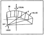
図1及び図2を参照すると、マルチスライス走査型イメージング・システム、例えば、コンピュータ断層撮影(CT)イメージング・システム10が、「第3世代」のCTイメージング・システムを表すガントリ12を含むものとして示されている。ガントリ12はX線源14を備えており、X線源14はガントリ12の反対側にある検出器アレイ18へ向かってX線ビーム16を投射する。検出器アレイ18は、患者22のような対象物を通過した投射X線ビームを検知する複数の検出器素子20を含む複数の検出器列(図示していない)によって形成されている。各々の検出器素子20は、入射するX線ビームの強度、従って対象物又は患者22を通過したビームの減弱度を表す電気信号を発生する。X線投影データを取得するための走査中、ガントリ12及びそれに装着された部品は回転中心24の周りを回転する。図2は一列の検出器素子20(すなわち、一検出器列)のみを示している。しかしながら、マルチスライス検出器アレイ18は、検出器素子20の複数の並列の検出器列を含んでいて、複数の準並列又は並列のスライスに対応する投影データを走査中に同時に取得することができる。
Referring to FIGS. 1 and 2, a multi-slice scanning imaging system, such as a computed tomography (CT)
ガントリ12の回転及びX線源14の動作はCTシステム10の制御機構26によって統制される。制御機構26は、X線源14に電力及びタイミング信号を供給するX線制御装置28と、ガントリ12の回転速度及び位置を制御するガントリ・モータ制御装置30とを含んでいる。制御機構26にはデータ収集システム(DAS)32も含まれており、該DAS32は、検出器素子20からのアナログ・データをサンプリングして、該データをその後の処理のためにディジタル信号へ変換する。画像再構成装置34がDAS32からサンプリングされ且つディジタル化されたX線データを受け取って、高速画像再構成を実行する。再構成された画像はコンピュータ36に入力として印加され、コンピュータ36は該画像を大容量記憶装置38に格納する。
The rotation of the
コンピュータ36はまた、キーボ−ドを備えたコンソール40を介してオペレータから指令及び走査パラメータも受け取る。付設された陰極線管表示装置42により、オペレータはコンピュータ36からの再構成された画像やその他のデータを観察することが可能になる。コンピュータ36はオペレータから供給された指令及びパラメータを使用して、DAS32、X線制御装置28及びガントリ・モータ制御装置30へ制御信号及び情報を供給する。加えて、コンピュータ36は、ガントリ12内に患者22を位置決めするために電動テーブル46を制御するテーブル・モータ制御装置44を動作させる。具体的に述べると、テーブル46は患者22の一部分をガントリ開口部48内へ通すように移動させる。
一実施形態において、コンピュータ36は、フレキシブル・ディスクやCD−ROMのようなコンピュータ読出し可能な媒体52から命令及び/又はデータを読み出すためのフレキシブル・ディスク・ドライブやCD−ROMドライブのようなデバイス50を含んでいる。別の実施形態では、コンピュータ36はファームウエア(図示していない)に記憶されている命令を実行する。コンピュータ36は本書で述べる機能を実行するようにプログラムされており、従って、本書で用いる用語「コンピュータ」とは当該技術分野でコンピュータと呼ばれている集積回路だけでなく、広義にコンピュータ、プロセッサ、マイクロプロセッサ、マイクロコンピュータ、プログラム可能な論理制御装置、特定用途向け集積回路、及びその他のプログラム可能な回路を表す。
In one embodiment, the
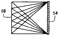
図3は、標準的なFDK(フェルドカンプ(Feldkamp)、デイヴィッド(David) 及びクレス(Kress) )ジオメトリイを例示している。FDKジオメトリイを使用すると、点放射線源14が検出器18に対向して配置される。検出器18は円筒(図示していない)の表面に沿って湾曲しており、該円筒の軸はZ軸に平行であり、線源14は、その軸がZ軸を含む円筒上を移動する。一般的なFDKデータ取得では、線源14は、Z=0でのX−Y平面内にある円である軌跡に沿って移動する。しかしながら、グランジート(Grangeat)によって実証されているように、この軌跡は、この単一のデータ集合を使用して走査の対象物22を正確に再構成することが不可能であるという意味で、完全ではない。
FIG. 3 illustrates standard FDK (Feldkamp, David and Kress) geometries. Using the FDK geometry, the
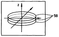
図4は、Z方向に移動し且つ角度θで円形軌道の周りを回転する線源14を使用して取得される複数の円軌跡58を例示する。一実施形態では、k番目の投影が次式に従って線源位置で取得される。
FIG. 4 illustrates a plurality of
[SID cos(θk) SID sin(θk) zk] 式(1)
ここで、
zk はZ軸上の一点で取得された投影kであり、
SID は線源画像検出器であり、
θは線源角度である。
[SID cos (θ k ) SID sin (θ k ) z k ] Equation (1)
here,
z k is the projection k acquired at one point on the Z axis,
SID is a source image detector
θ is the source angle.
一般的なFDK軌跡は次式のように定義される。 A general FDK trajectory is defined as:
θk=2π/P, zi=0 式(2)
ここで、
Pは線源14の各々の軌道で取得されるビューの数であり、
zk はZ軸上の一点で取得される投影kである。
θ k = 2π / P, z i = 0 Equation (2)
here,
P is the number of views acquired in each trajectory of the
z k is a projection k acquired at one point on the Z axis.
例えば、複数の円軌跡、すなわち、総数L個の円が異なるZ位置で逐次的に取得される場合、式(2)のパラメータ表現の項は次式のように表すことができる。 For example, when a plurality of circular trajectories, that is, a total of L circles, are sequentially acquired at different Z positions, the parameter expression term in Expression (2) can be expressed as the following expression.
θk=2πk/P, zk=a1 , 0≦k<P
θk=2π(k−P)/P, zk=a2 , P≦k<2P
:
:
θk=2π(k−(L-1)P)/P, zk=aL , (L-2)P≦k<(L-1)P
式(3)
ここで、
kは単一のビューであり、
lはZ軸上の点zで取得される単一の円であり、
Lは取得される円の総数であり、
θk はビューk取得するときの線源角度であり、
Pは各々の線源軌道について取得されるビューの数であり、
zk はZ軸上の点zで取得される投影kであり、
an はZ軸上の一点であり、ここでn=1…Lである。
θ k = 2πk / P, z k = a 1 , 0 ≦ k <P
θ k = 2π (k−P) / P, z k = a 2 , P ≦ k <2P
:
:
θ k = 2π (k− (L−1) P) / P, z k = a L , (L−2) P ≦ k <(L−1) P
Formula (3)
here,
k is a single view,
l is a single circle obtained at point z on the Z axis,
L is the total number of circles acquired,
θ k is the source angle when acquiring view k,
P is the number of views acquired for each source trajectory,
z k is the projection k acquired at point z on the Z axis,
a n is a point on the Z axis, which is where n = 1 ... L.
図5は、移動する線源14と不動の検出器18(すなわち、検出器18の中心がZ=0に固定されている)とにより取得されるサンプリング・パターンを例示し、線源は本書に記載した手法の内の少なくとも一つの手法を使用して移動させる。図6は、移動する線源14と移動する検出器18とにより取得されるサンプリング・パターン(すなわち、「歩進−撮影(step-and-shoot)」モードでの一連の標準的な円取得)を例示する。模範的な実施形態では、線源14の移動は、限定ではなく、例として挙げると、ライン形状の線源、反転円錐及び複数の管のような複数の技術を使用して行うことができる。
FIG. 5 illustrates a sampling pattern acquired by a moving
図6に示した連続する類似の軌跡についての再構成アルゴリズムは、次の手法、すなわち、各々の「円(circle)」を独立に処理して、関心領域(ROI)のL個の別々の再構成を(線源14の各々のZ位置について1つずつ)行う手法を使用して、構成される。各々の円は次式に従ってFDKアルゴリズムを使用して再構成することができる。 The reconstruction algorithm for successive similar trajectories shown in FIG. 6 uses the following approach: each “circle” is processed independently to produce L separate reconstructions of the region of interest (ROI). It is configured using a technique that performs the configuration (one for each Z position of the source 14). Each circle can be reconstructed using the FDK algorithm according to the following equation:
f1(x,y,z),f2(x,y,z),....,fL(x,y,z) 式(4)
ここで、式(4)は「コンポーネント再構成」と称される。
f 1 (x, y, z), f 2 (x, y, z),..., f L (x, y, z) Equation (4)
Here, Expression (4) is referred to as “component reconfiguration”.
更に、各々のZ位置alについて、FDK再構成は平面z=alでの扇形ビーム再構成へ簡単化される。従って、不完全な性質のデータに起因する画像品質は、データが線源14を含むZ平面から遠ざかって取得されるにつれて単調に減少する。
Furthermore, for each Z position a l , the FDK reconstruction is simplified to a fan beam reconstruction at the plane z = a l . Therefore, the image quality due to imperfect data decreases monotonically as the data is acquired away from the Z plane containing the
上述の再構成は、次式に従って空間座標の関数として変化する重みを使用して組み合わされる。 The above reconstructions are combined using weights that vary as a function of spatial coordinates according to the following equation:

L個の再構成は、所与のZ位置に最も近い線源平面に対応するコンポーネント再構成の方へ最終再構成をバイアする重みを使用して組み合わされる。例えば、重みがZのみの関数として適用される場合、円は次式に従ってZ軸に沿って等間隔に配設される。 The L reconstructions are combined using a weight that biases the final reconstruction toward the component reconstruction corresponding to the source plane closest to the given Z position. For example, if the weight is applied as a function of Z only, the circles are arranged at equal intervals along the Z axis according to the following equation:
al=(l−L/2)・Δz 式(6)
ここで、
lは1つの円であり、
Lはlの円の数であり、
ΔzはZ軸位置における変化である。
a l = (l−L / 2) · Δz Formula (6)
here,
l is a circle,
L is the number of circles of l,
Δz is a change in the Z-axis position.
再構成は次式に従って組み合わされる。 The reconstruction is combined according to the following formula:
更に、重みが次式
w(z) = 1 (z=0の場合)
w(z) = 0 (z=(l−L/2)・Δa,l=0...L-1の場合)
式(8)
のように定義される補間特性を満足する場合、各々のコンポーネント再構成が、線源の円を含んでいる平面について適切なz位置では正確であるので、最終再構成fは正確である。
Furthermore, the weight is the following formula w (z) = 1 (when z = 0)
w (z) = 0 (in the case of z = (l−L / 2) · Δa, l = 0... L−1)
Formula (8)
The final reconstruction f is accurate because each component reconstruction is accurate at the appropriate z-position for the plane containing the source circle.
点(x,y,z)を再構成するために、平均(重み付け平均)円錐角に比例する重み付け関数を用いてもよい。この比例重み付け関数により、円錐角が(x,y)の関数として変化する。同じZ値について、円錐角はX線源14(図1に示す)までの距離の増加につれて減少する。 A weighting function proportional to the average (weighted average) cone angle may be used to reconstruct the point (x, y, z). This proportional weighting function changes the cone angle as a function of (x, y). For the same Z value, the cone angle decreases with increasing distance to the X-ray source 14 (shown in FIG. 1).
図7は、焦点スポットの移動中にガントリ12(図1に示す)を回転させて取得されたサンプリング・パターンである。前に述べた円の積重ねLは、可能な1つのサンプリング・パターンである。しかし、移動可能な焦点スポットによりこの取得パターンを実現するためには、対象物を中心にして焦点スポットを数回にわたって回転させて、各回転毎にz位置を変更するか、或いは、ガントリ12を不動にしておいて、各位置θについて複数のz位置z=al にわたって焦点スポットを走査させてもよい。もし各位置θについて複数のz位置z=al にわたって焦点スポットを走査させ、且つ焦点スポットの移動中にガントリ12を回転させた場合、焦点スポットは実効的に図7に示されるように複数の位置に逐次的に動かされる。
FIG. 7 is a sampling pattern acquired by rotating the gantry 12 (shown in FIG. 1) during movement of the focal spot. The previously described circle stack L is one possible sampling pattern. However, to achieve this acquisition pattern with a movable focal spot, the focal spot is rotated several times around the object and the z position is changed for each rotation, or the
所与のz位置へ戻る時間が一定であると仮定すると、線源サンプリング・パターンは、各々のコンポーネント再構成を等しい数の等間隔のビューにより実行できることを保証する。しかしながら、この構成には2つの問題がある。第1の問題は、対象物22(図1に示す)の中心を通過する射線の数が、ROIの2つの平坦な面上の任意の点を通過する射線の数よりも遥かに多いことである。最終再構成がフィルタ補正逆投影の重み付けされた和であるので、これはノイズ特性がボリューム全体にわたって一様にならない恐れがあることを意味する。第2の問題は、この同じ特性が、すなわち、ボリュームの中心がオーバーサンプリングされることが、所与の分解能を得るために必要とされるビューの数が対象物22(図1に示す)の画像を再構成するのに必要な数よりも多いことを意味することである。具体的に述べると、図7に示されている分離可能な「円の積重ね」のサンプリング・パターンがL*Pサンプルを必要とする。ここで、Lは個別の円lの数であり、Pは各々の円lにおけるビューの数である。 Assuming that the time to return to a given z position is constant, the source sampling pattern ensures that each component reconstruction can be performed with an equal number of equally spaced views. However, this configuration has two problems. The first problem is that the number of rays passing through the center of the object 22 (shown in FIG. 1) is much greater than the number of rays passing through any point on the two flat surfaces of the ROI. is there. Since the final reconstruction is a weighted sum of filtered backprojections, this means that the noise characteristics may not be uniform across the volume. The second problem is that this same property, that is, that the center of the volume is oversampled, the number of views required to obtain a given resolution of the object 22 (shown in FIG. 1). It means more than is necessary to reconstruct the image. Specifically, the separable “circle stack” sampling pattern shown in FIG. 7 requires L * P samples. Where L is the number of individual circles l and P is the number of views in each circle l.
例えば、線源の円lを含む各々の平面において充分な画像品質を得るために1000のビュー(P)が必要とされると共に、線源の軌道の数が10、すなわちL=10である場合、必要とされるビューの総数は10000、すなわち、L*P=10000である。中心平面を通過するビューの多くは冗長であるので、全体のビュー(P)を減らすことができる。ROIの2つの「面」を除いて、すなわち、最小及び最大Z位置を除いて、再構成ボリューム内の各点は、それらを多数の交差射線が通過する結果として方位方向にオーバーサンプリングされる。このサンプリング・パターンは、オーバーサンプリングを補正するために一層良好な射線分布特性を持つ一層複雑なサンプリング・パターンを使用するように修正することができる。 For example, if 1000 views (P) are required to obtain sufficient image quality in each plane including the source circle l and the number of source trajectories is 10, ie L = 10 , The total number of views required is 10,000, ie L * P = 10000. Many of the views that pass through the central plane are redundant, so the overall view (P) can be reduced. Except for the two “faces” of the ROI, ie, the minimum and maximum Z positions, each point in the reconstruction volume is oversampled in the azimuth direction as a result of the passage of multiple intersecting rays through them. This sampling pattern can be modified to use a more complex sampling pattern with better ray distribution characteristics to correct oversampling.
図8は、対象物の画像を再構成するための方法60の流れ図である。方法60は、z軸上の第1の位置で第1の数のビューを取得する工程62と、前記第1の位置とは異なるz軸上の第2の位置で、前記第1の数とは異なる第2の数のビューを取得する工程64と、前記第1の位置及び第2の位置とは異なるz軸上の第3の位置で、前記第1の数に等しい第3の数のビューを取得する工程66とを含んでいる。
FIG. 8 is a flowchart of a
模範的な実施形態では、方法60は以下の制約を含み、焦点スポットが任意の所与の時点で正確に1つの(θ,Z)位置にある。更に、複数のコンポーネント再構成に分離されたとき、各々のコンポーネント再構成lはそのコンポーネントの平面内の円上の等間隔に配置されたビューから形成される。その上、各々のFDK再構成は等角度間隔のデータで実行され、またサンプル分布は制御可能である。模範的な実施形態では、サンプル分布は、再構成ボリュームの内部で異なる射線密度が得られるように保証し易くするためにサンプリング方式のパラメータを変更することによって制御することができる。
In the exemplary embodiment,
図9は、方法60を使用して取得される二進ツリー・サンプリング・パターン70を例示する。使用の際、放射線源14(図1に示す)は、第1の位置76のような位置74へZ軸72に沿って平行移動可能である。線源14はZ軸72を中心として円形軌道で回転させて、第1の数のビュー78が第1の数の放射線源位置80で取得されるようにする。
FIG. 9 illustrates a binary tree sampling pattern 70 obtained using the
放射線源14は、第1の位置76とは異なるZ軸72上の第2の位置82のような別の位置74へZ軸72に沿って平行移動させる。放射線源14は再び円形軌道で回転させて、第2の数のビュー84が第2の数の放射線源位置86で取得されるようにする。この場合、第2の数のビュー84は第1の数のビュー78の半分である。次いで、放射線源14は、第1の位置76及び第2の位置82とは異なるz軸72上の第3の位置90のような別の位置74へ平行移動させて、第1の数のビュー78と同等な第3の数のビュー92が第3の数の放射線源位置94で取得されるようにする。
The
使用中、放射線源14はZ軸72に沿って関心領域(ROI)の第1の面100へ平行移動させる。関心領域(ROI)の第1の面100が取得されるまで、各Z軸位置74で所定数のビューを取得する。図示のように、各々の円58についてのビューの数は、中心平面106についてのビューが取得されるまで、第1の面100から半分に減少させる。二進ツリー・サンプリング・パターンは中心平面106に関して対称である。例えば、第1の面100及び第2の面104、すなわち、最小及び最大Z位置がそれぞれ1000個のビューを含んでいる場合、中心平面106に一層近い次の2つの円58は500個のビューを含む、と云うようになる。より内側の円58は、これらの平面内の点が他の円58上で始まる射線からの寄与分を受けるので、より少ないビューを含むことができる。図9に示されているように、パターンは複数の円58(又は一定のZ位置の集合)に分離され、その各々は隣接の円58からの寄与分を補完する一様に間隔を置いた角度サンプルを有する。
In use, the
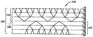
図10は、方法60を使用して取得されるオフセット二進ツリー・サンプリング・パターン110を例示する。図示のように、下側のビュー集合112は上側のビュー集合114とは食い違い配置して、Z=0平面すなわち中心平面106で角度方向サンプリング速度を2倍にすることができる。ROI102をカバーするのに必要なビューの最大数は、オフセット二進ツリー・サンプリング・パターンを使用するとき線源の点について、Z位置の数すなわち位置74の数に関係なく、4*Pである。この理由は、P+P/2+P/4+…P/N=2*Pであり、且つパターンが中心平面106に対して対称であるからである。従って、必要とされるビューの数は、使用する円の数に無関係である。
FIG. 10 illustrates an offset binary
本発明の様々な特定の実施形態について説明したが、当業者には本発明が特許請求の範囲に記載の精神および範囲内で修正して実施できることが認められよう。 While various specific embodiments of the invention have been described, those skilled in the art will recognize that the invention can be practiced with modification within the spirit and scope of the appended claims.
10 コンピュータ断層撮影(CT)イメージング・システム
12 ガントリ
14 X線源
16 X線ビーム
18 検出器アレイ
20 検出器素子
22 患者
24 回転中心
26 制御機構
42 陰極線管表示装置
48 ガントリ開口部
50 デバイス
52 コンピュータ読出し可能な媒体
58 円軌跡
70 サンプリング・パターン
72 Z軸
74 Z軸上の位置
76 Z軸上の第1の位置
78 第1の数のビュー
80 第1の数の放射線源位置
82 Z軸上の第2の位置
84 第2の数のビュー
86 第2の数の放射線源位置
90 Z軸上の第3の位置
92 第3の数のビュー
94 第3の数の放射線源位置
100 第1の面
102 ROI
104 第2の面
106 中心平面
110 オフセット二進ツリー・サンプリング・パターン
112 下側ビュー集合
114 上側ビュー集合
DESCRIPTION OF
104
Claims (5)
検出器アレイ(18)と、少なくとも1つの放射線源(14)と、前記検出器アレイ及び前記放射線源に結合されているコンピュータ(36)とを有し、
前記コンピュータは、
z軸上の第1の位置で第1の角度サンプル間隔でビューを取得し(62)、
前記第1の位置とは異なるz軸上の第2の位置で、前記第1の角度サンプル間隔よりも広い第2の角度サンプル間隔でビューを取得し(64)、
前記第1の位置及び第2の位置とは異なるz軸上の第3の位置で、前記第1の角度サンプル間隔に等しい第3の角度サンプル間隔でビューを取得する(66)ように構成されていること、
を特徴とするコンピュータ断層撮影(CT)イメージング・システム。A computed tomography (CT) imaging system (10) for acquiring a plurality of views of an object (22) comprising:
A detector array (18), at least one radiation source (14), and a computer (36) coupled to the detector array and the radiation source;
The computer
obtaining a view at a first angular sample interval at a first position on the z-axis (62);
Obtaining a view at a second position on the z-axis different from the first position at a second angular sample interval that is wider than the first angular sample interval (64);
The view is configured (66) to acquire a view at a third angular sample interval equal to the first angular sample interval at a third location on the z-axis that is different from the first and second positions. That
A computed tomography (CT) imaging system.
前記第2の位置で、前記第2の数のビューを取得する(64)ために、z=0となる中心平面で前記第1の数よりも少ない前記第2の数のビューを取得するように構成されている、コンピュータ(36)。A claim 1 according computer (36), is the computer, to obtain a first number of views in the first position (62), wherein in a second position, said first number Is configured to obtain a different second number of views (64) and to obtain a third number of views equal to the first number at the third position;
To obtain (64) the second number of views at the second position, so as to obtain the second number of views less than the first number in a central plane where z = 0. A computer (36) configured as follows.
前記第1の位置とは異なるz軸上の第2の位置で、前記第1の数とは異なる第2の数のビューを取得する(64)ために、前記第1の数の半分である第2の数のビューを取得するように構成されている、コンピュータ(36)。A claim 1 according computer (36), is the computer, to obtain a first number of views in the first position (62), wherein in a second position, said first number Are configured to obtain a different second number of views (64) and to obtain a third number of views equal to the first number at the third position;
Half of the first number to obtain (64) a second number of views different from the first number at a second position on the z-axis different from the first position A computer (36) configured to obtain a second number of views.
前記第1乃至第3の数のビューは別々に処理されて、別々の再構成が生成され、
該別々の処理による複数の再構成が組み合わされる、コンピュータ(36)。5. A computer (36) according to any of claims 2 to 4, wherein the computer further rotates the radiation source (14) in a first circle to obtain the first number of views. , Rotate the radiation source in a second circle to acquire the second number of views, and rotate the radiation source in a third circle to acquire the third number of views Is configured as
The first to third numbers of views are processed separately to generate separate reconstructions;
A computer (36) in which a plurality of reconstructions by the separate processes are combined.
Applications Claiming Priority (1)
| Application Number | Priority Date | Filing Date | Title |
|---|---|---|---|
| US10/176,427 US6597756B1 (en) | 2002-06-19 | 2002-06-19 | Methods and apparatus for multi-slice image reconstruction |
Publications (3)
| Publication Number | Publication Date |
|---|---|
| JP2004033758A JP2004033758A (en) | 2004-02-05 |
| JP2004033758A5 JP2004033758A5 (en) | 2006-07-13 |
| JP4460853B2 true JP4460853B2 (en) | 2010-05-12 |
Family
ID=22644317
Family Applications (1)
| Application Number | Title | Priority Date | Filing Date |
|---|---|---|---|
| JP2003153796A Expired - Fee Related JP4460853B2 (en) | 2002-06-19 | 2003-05-30 | Method and apparatus for multi-slice image reconstruction |
Country Status (3)
| Country | Link |
|---|---|
| US (1) | US6597756B1 (en) |
| EP (1) | EP1374775A1 (en) |
| JP (1) | JP4460853B2 (en) |
Families Citing this family (9)
| Publication number | Priority date | Publication date | Assignee | Title |
|---|---|---|---|---|
| US6687393B1 (en) * | 1999-07-16 | 2004-02-03 | General Electric Company | Efficient methods and apparatus for resampling three dimensional datasets |
| US20050201605A1 (en) * | 2004-03-11 | 2005-09-15 | Jianying Li | Methods and apparatus for CT smoothing to reduce artifacts |
| US7173996B2 (en) * | 2004-07-16 | 2007-02-06 | General Electric Company | Methods and apparatus for 3D reconstruction in helical cone beam volumetric CT |
| US7734079B2 (en) * | 2004-09-28 | 2010-06-08 | General Electric Company | Methods and apparatus for image reconstruction |
| US7826684B2 (en) * | 2005-09-21 | 2010-11-02 | Siemens Medical Solutions Usa, Inc. | Optimization and view dependency reduction for processing slice-based volumes |
| JP4679348B2 (en) * | 2005-11-22 | 2011-04-27 | ジーイー・メディカル・システムズ・グローバル・テクノロジー・カンパニー・エルエルシー | X-ray CT system |
| US8031829B2 (en) * | 2007-10-26 | 2011-10-04 | General Electric Company | Method for analytic reconstruction of cone-beam projection data for multi-source inverse geometry CT systems |
| US20110064202A1 (en) * | 2008-05-15 | 2011-03-17 | Koninklijke Philips Electronics N.V. | Method and system for generating an x-ray beam |
| US10602993B2 (en) * | 2018-05-18 | 2020-03-31 | FMI Medical Systems Co., Ltd. | Image reconstruction for Z-flying focal spot tomography |
Family Cites Families (13)
| Publication number | Priority date | Publication date | Assignee | Title |
|---|---|---|---|---|
| JPH0728862B2 (en) * | 1989-02-13 | 1995-04-05 | 株式会社東芝 | CT device |
| US5187659A (en) * | 1990-09-04 | 1993-02-16 | General Electric Company | Cone beam scanning trajectories for three-dimensional computerized tomography data acquisition where object is larger than the field of view |
| US5396528A (en) | 1991-06-28 | 1995-03-07 | General Electric Company | Tomographic image reconstruction using cross-plane rays |
| US5469486A (en) * | 1992-08-07 | 1995-11-21 | General Electric Company | Projection domain reconstruction method for helical scanning computed tomography apparatus with multi-column detector array employing overlapping beams |
| US5541971A (en) | 1993-09-06 | 1996-07-30 | Kabushiki Kaisha Toshiba | X-ray computerized tomography apparatus |
| US5448607A (en) | 1994-02-08 | 1995-09-05 | Analogic Corporation | X-ray tomography system with gantry pivot and translation control |
| US5673300A (en) | 1996-06-11 | 1997-09-30 | Wisconsin Alumni Research Foundation | Method of registering a radiation treatment plan to a patient |
| US5812628A (en) | 1996-12-12 | 1998-09-22 | General Electric Company | Methods and apparatus for detecting partial volume image artifacts |
| US6115447A (en) | 1997-11-07 | 2000-09-05 | General Electric Company | Multi-slice biopsy with single slice computed tomography |
| US6256369B1 (en) | 1999-03-31 | 2001-07-03 | Analogic Corporation | Computerized tomography scanner with longitudinal flying focal spot |
| US6385279B1 (en) | 1999-08-27 | 2002-05-07 | General Electric Company | Methods and apparatus for positioning a CT imaging x-ray beam |
| US6307910B1 (en) * | 2000-01-07 | 2001-10-23 | Ge Medical Systems Global Technology Company, Llc | Methods and apparatus for reduced radiation coronary computed tomography imaging |
| DE10038328A1 (en) * | 2000-08-05 | 2002-02-14 | Philips Corp Intellectual Pty | Computer tomograph with conical rays and helical relative movement |
-
2002
- 2002-06-19 US US10/176,427 patent/US6597756B1/en not_active Expired - Lifetime
-
2003
- 2003-05-30 JP JP2003153796A patent/JP4460853B2/en not_active Expired - Fee Related
- 2003-06-06 EP EP03253605A patent/EP1374775A1/en not_active Withdrawn
Also Published As
| Publication number | Publication date |
|---|---|
| US6597756B1 (en) | 2003-07-22 |
| EP1374775A1 (en) | 2004-01-02 |
| JP2004033758A (en) | 2004-02-05 |
Similar Documents
| Publication | Publication Date | Title |
|---|---|---|
| US6754299B2 (en) | Methods and apparatus for weighting of computed tomography data | |
| US6452996B1 (en) | Methods and apparatus utilizing generalized helical interpolation algorithm | |
| EP1374776B1 (en) | Methods and apparatus for operating a radiation source | |
| US6944260B2 (en) | Methods and apparatus for artifact reduction in computed tomography imaging systems | |
| JP4993163B2 (en) | Method and apparatus for reconstruction of tilted cone beam data | |
| JP2006314856A (en) | System of producing tomgraphic image of object, and volume-measuring type computerized tomography system | |
| US6876718B2 (en) | Scatter correction methods and apparatus | |
| IL124014A (en) | Methods and apparatus for scanning an object in a computed tomography system | |
| US6341154B1 (en) | Methods and apparatus for fast CT imaging helical weighting | |
| US6904117B2 (en) | Tilted gantry helical cone-beam Feldkamp reconstruction for multislice CT | |
| US6654440B1 (en) | Methods and apparatus for computed tomography scanning using a two-dimensional radiation source | |
| US6381297B1 (en) | High pitch reconstruction of multislice CT scans | |
| US7050527B2 (en) | Methods and apparatus for artifact reduction in cone beam CT image reconstruction | |
| JP4460853B2 (en) | Method and apparatus for multi-slice image reconstruction | |
| US7215734B2 (en) | Method and system for three-dimensional reconstruction of images | |
| JP2004113785A (en) | Image formation method and ct unit for implementing the same in computerized tomography | |
| US7583777B2 (en) | Method and apparatus for 3D reconstruction of images | |
| JP2002034970A (en) | Method and device for spiral reconstitution in multi-slice ct scan | |
| US6798860B1 (en) | Methods and apparatus for deconvolving imaging data | |
| US6654442B2 (en) | Methods and apparatus for weighting projection data | |
| US6999550B2 (en) | Method and apparatus for obtaining data for reconstructing images of an object | |
| US7539281B2 (en) | Methods and apparatus for reconstruction in helical cone beam volumetric CT | |
| US7173996B2 (en) | Methods and apparatus for 3D reconstruction in helical cone beam volumetric CT | |
| US7013034B2 (en) | Methods and apparatus for reconstructing an image of an object |
Legal Events
| Date | Code | Title | Description |
|---|---|---|---|
| A521 | Request for written amendment filed |
Free format text: JAPANESE INTERMEDIATE CODE: A523 Effective date: 20060525 |
|
| A621 | Written request for application examination |
Free format text: JAPANESE INTERMEDIATE CODE: A621 Effective date: 20060525 |
|
| A131 | Notification of reasons for refusal |
Free format text: JAPANESE INTERMEDIATE CODE: A131 Effective date: 20090324 |
|
| A521 | Request for written amendment filed |
Free format text: JAPANESE INTERMEDIATE CODE: A523 Effective date: 20090526 |
|
| RD02 | Notification of acceptance of power of attorney |
Free format text: JAPANESE INTERMEDIATE CODE: A7422 Effective date: 20090526 |
|
| RD04 | Notification of resignation of power of attorney |
Free format text: JAPANESE INTERMEDIATE CODE: A7424 Effective date: 20090526 |
|
| A131 | Notification of reasons for refusal |
Free format text: JAPANESE INTERMEDIATE CODE: A131 Effective date: 20091222 |
|
| A521 | Request for written amendment filed |
Free format text: JAPANESE INTERMEDIATE CODE: A523 Effective date: 20100105 |
|
| TRDD | Decision of grant or rejection written | ||
| A01 | Written decision to grant a patent or to grant a registration (utility model) |
Free format text: JAPANESE INTERMEDIATE CODE: A01 Effective date: 20100126 |
|
| A01 | Written decision to grant a patent or to grant a registration (utility model) |
Free format text: JAPANESE INTERMEDIATE CODE: A01 |
|
| A61 | First payment of annual fees (during grant procedure) |
Free format text: JAPANESE INTERMEDIATE CODE: A61 Effective date: 20100215 |
|
| R150 | Certificate of patent or registration of utility model |
Ref document number: 4460853 Country of ref document: JP Free format text: JAPANESE INTERMEDIATE CODE: R150 Free format text: JAPANESE INTERMEDIATE CODE: R150 |
|
| FPAY | Renewal fee payment (event date is renewal date of database) |
Free format text: PAYMENT UNTIL: 20130219 Year of fee payment: 3 |
|
| FPAY | Renewal fee payment (event date is renewal date of database) |
Free format text: PAYMENT UNTIL: 20130219 Year of fee payment: 3 |
|
| FPAY | Renewal fee payment (event date is renewal date of database) |
Free format text: PAYMENT UNTIL: 20140219 Year of fee payment: 4 |
|
| R250 | Receipt of annual fees |
Free format text: JAPANESE INTERMEDIATE CODE: R250 |
|
| R250 | Receipt of annual fees |
Free format text: JAPANESE INTERMEDIATE CODE: R250 |
|
| R250 | Receipt of annual fees |
Free format text: JAPANESE INTERMEDIATE CODE: R250 |
|
| R250 | Receipt of annual fees |
Free format text: JAPANESE INTERMEDIATE CODE: R250 |
|
| R250 | Receipt of annual fees |
Free format text: JAPANESE INTERMEDIATE CODE: R250 |
|
| R250 | Receipt of annual fees |
Free format text: JAPANESE INTERMEDIATE CODE: R250 |
|
| R250 | Receipt of annual fees |
Free format text: JAPANESE INTERMEDIATE CODE: R250 |
|
| R250 | Receipt of annual fees |
Free format text: JAPANESE INTERMEDIATE CODE: R250 |
|
| LAPS | Cancellation because of no payment of annual fees |