JP4460823B2 - Method and apparatus for supporting and promoting blood vessel analysis - Google Patents
Method and apparatus for supporting and promoting blood vessel analysis Download PDFInfo
- Publication number
- JP4460823B2 JP4460823B2 JP2002356102A JP2002356102A JP4460823B2 JP 4460823 B2 JP4460823 B2 JP 4460823B2 JP 2002356102 A JP2002356102 A JP 2002356102A JP 2002356102 A JP2002356102 A JP 2002356102A JP 4460823 B2 JP4460823 B2 JP 4460823B2
- Authority
- JP
- Japan
- Prior art keywords
- tube structure
- cursor
- computer
- point
- path
- Prior art date
- Legal status (The legal status is an assumption and is not a legal conclusion. Google has not performed a legal analysis and makes no representation as to the accuracy of the status listed.)
- Expired - Fee Related
Links
- 238000000034 method Methods 0.000 title claims abstract description 82
- 238000004458 analytical method Methods 0.000 title description 6
- 210000004204 blood vessel Anatomy 0.000 title description 2
- 230000001737 promoting effect Effects 0.000 title 1
- 230000001902 propagating effect Effects 0.000 claims description 9
- 230000005855 radiation Effects 0.000 claims description 7
- 238000002059 diagnostic imaging Methods 0.000 claims description 6
- 210000005239 tubule Anatomy 0.000 claims description 2
- 238000010586 diagram Methods 0.000 description 32
- 239000013598 vector Substances 0.000 description 26
- 238000003384 imaging method Methods 0.000 description 21
- 238000002591 computed tomography Methods 0.000 description 14
- 238000013459 approach Methods 0.000 description 13
- 230000008569 process Effects 0.000 description 6
- 239000011159 matrix material Substances 0.000 description 5
- 230000007246 mechanism Effects 0.000 description 4
- 238000013170 computed tomography imaging Methods 0.000 description 3
- 238000005259 measurement Methods 0.000 description 3
- 238000012360 testing method Methods 0.000 description 3
- 230000002238 attenuated effect Effects 0.000 description 2
- 210000001072 colon Anatomy 0.000 description 2
- 238000007689 inspection Methods 0.000 description 2
- 238000012545 processing Methods 0.000 description 2
- 230000000644 propagated effect Effects 0.000 description 2
- 230000006439 vascular pathology Effects 0.000 description 2
- 230000000007 visual effect Effects 0.000 description 2
- 206010002329 Aneurysm Diseases 0.000 description 1
- 208000031481 Pathologic Constriction Diseases 0.000 description 1
- 238000005452 bending Methods 0.000 description 1
- 230000005540 biological transmission Effects 0.000 description 1
- 238000004364 calculation method Methods 0.000 description 1
- 238000005266 casting Methods 0.000 description 1
- 230000008859 change Effects 0.000 description 1
- 238000004590 computer program Methods 0.000 description 1
- 238000010276 construction Methods 0.000 description 1
- 210000004351 coronary vessel Anatomy 0.000 description 1
- 238000013479 data entry Methods 0.000 description 1
- 230000010339 dilation Effects 0.000 description 1
- 239000004973 liquid crystal related substance Substances 0.000 description 1
- 238000012986 modification Methods 0.000 description 1
- 230000004048 modification Effects 0.000 description 1
- 230000007170 pathology Effects 0.000 description 1
- 238000002600 positron emission tomography Methods 0.000 description 1
- 238000003825 pressing Methods 0.000 description 1
- 230000002250 progressing effect Effects 0.000 description 1
- 238000011002 quantification Methods 0.000 description 1
- 230000009467 reduction Effects 0.000 description 1
- 230000036262 stenosis Effects 0.000 description 1
- 208000037804 stenosis Diseases 0.000 description 1
- 210000003437 trachea Anatomy 0.000 description 1
- 238000012546 transfer Methods 0.000 description 1
- 238000002604 ultrasonography Methods 0.000 description 1
- 230000002792 vascular Effects 0.000 description 1
- 210000005166 vasculature Anatomy 0.000 description 1
- 230000037303 wrinkles Effects 0.000 description 1
Images


Classifications
-
- G—PHYSICS
- G06—COMPUTING; CALCULATING OR COUNTING
- G06T—IMAGE DATA PROCESSING OR GENERATION, IN GENERAL
- G06T19/00—Manipulating 3D models or images for computer graphics
- G06T19/003—Navigation within 3D models or images
-
- G—PHYSICS
- G06—COMPUTING; CALCULATING OR COUNTING
- G06T—IMAGE DATA PROCESSING OR GENERATION, IN GENERAL
- G06T2210/00—Indexing scheme for image generation or computer graphics
- G06T2210/41—Medical
Landscapes
- Engineering & Computer Science (AREA)
- Software Systems (AREA)
- General Physics & Mathematics (AREA)
- Theoretical Computer Science (AREA)
- Computer Graphics (AREA)
- Computer Hardware Design (AREA)
- General Engineering & Computer Science (AREA)
- Physics & Mathematics (AREA)
- Radar, Positioning & Navigation (AREA)
- Remote Sensing (AREA)
- Apparatus For Radiation Diagnosis (AREA)
- Image Processing (AREA)
- Magnetic Resonance Imaging Apparatus (AREA)
- Measuring And Recording Apparatus For Diagnosis (AREA)
- Image Analysis (AREA)
- Analysing Materials By The Use Of Radiation (AREA)
Abstract
Description
【0001】
【発明の背景】
本発明は一般的には、血管画像の解析の方法及び装置に関し、さらに具体的には、計算機式断層写真法撮像、MR撮像、及び3D放射線撮像から得られた画像による放射線学的検査時に放射線科医師等の医療従事者が測定及び報告を準備するのを支援する方法及び装置に関する。
【0002】
少なくとも幾つかの計算機式断層写真法(CT)イメージング・システム構成においては、X線源がファン(扇形)形状のビームを投射し、このビームは、デカルト座標系のXY平面であって、一般に「イメージング(撮像)平面」と呼ばれる平面内に位置するようにコリメートされる。X線ビームは患者等の被撮像物体を透過する。ビームは物体によって減弱された後に放射線検出器のアレイに入射する。検出器アレイで受光される減弱したビーム放射線の強度は、物体によるX線ビームの減弱量に依存している。アレイ内の各々の検出器素子が、検出器の位置でのビーム減弱の測定値である別個の電気信号を発生する。すべての検出器からの減弱測定値を別個に取得して透過プロファイル(断面)を形成する。
【0003】
公知の第3世代CTシステムでは、X線源及び検出器アレイは、X線ビームが物体と交差する角度が定常的に変化するように撮像平面内で被撮像物体の周りをガントリと共に回転する。X線源は典型的には、焦点においてX線ビームを照射するX線管を含んでいる。X線検出器は典型的には、検出器で受光したX線ビームをコリメートするコリメータ、コリメータに隣接して設けられているシンチレータ、及びシンチレータに隣接して設けられている光検出器を含んでいる。
【0004】
計算機式断層写真法(CT)撮像、並びに磁気共鳴(MR)撮像及び3DX線撮像(3DXR)の一つの応用に管解析がある。血管病状のX線による定量化及び解析は、長さ、断面寸法、角度、及び関連するパラメータを定量化して狭窄又は動脈瘤パラメータを評価することを求められている放射線科医師にとって重要である。幾つかの公知のイメージング・システムでは、CT、MR又は3DXRのような三次元データを用いて血管病状の解析を行なう。
【特許文献1】
米国特許第5630034号
【0005】
【発明が解決しようとする課題】
視覚的な病状解析は、操作者が彎曲している可能性のある構造を追跡しなければならないため困難な場合がある。上述のイメージング・システムは、始点と終点との間の経路を位置決定するための方法を含むことができ、すると操作者はスライダー又はスクロールバーのような単純なインタフェイス装置の助けを借りて算出経路に沿って追跡を行なうが、この方法では経路を画定して算出するのに必要な計算機時間が長くなる可能性がある。さらに、閉塞又は不連続な経路がある場合には、構造を視覚化するのに追加の工程が必要とされることもある。
【0006】
【課題を解決するための手段】
一実施形態では、患者の管構造を解析する方法を提供する。この方法は、患者の管構造を表わす表示管構造の内部でカーソル第一の位置を受け取る工程と、受け取ったカーソル第一の位置にのみ基づいて管構造内で経路を決定する工程と、カーソル第二の位置まで所定の方向に所定の距離だけ経路に沿ってカーソルを移動させる工程とを含んでいる。
【0007】
もう一つの実施形態では、時間の経過にわたって管構造を再表示する方法を提供する。この方法は、同じ管構造を表わす少なくとも第一の時刻での第一の三次元データ集合及び第二の時刻での第二の三次元データ集合を形成する工程と、第一の三次元データ集合の第一のビュー及び第二の三次元データ集合の第二のビューを形成する工程と、第一のビュー内で第一の三次元位置に第一のカーソルを配置すると共に、第一のビューにおける第一のカーソル位置に対応する第二のビュー内での第一の三次元位置に第二のカーソルを配置する工程とを含んでいる。この方法はまた、管構造内で経路を決定する工程と、第一のビュー及び第二のビューの少なくとも一方においてカーソル位置からの方向を画定する工程と、第一のカーソル第二の位置まで所定の方向に所定の距離だけ上述の決定した経路に沿って第一のカーソルを移動させると共に、第二のカーソル第二の位置まで所定の方向に所定の距離だけ上述の決定した経路に沿って第二のカーソルを移動させる工程とを含んでいる。
【0008】
さらにもう一つの実施形態では、患者の管構造を解析するためのコンピュータにより実行可能なプログラムで符号化されているコンピュータ読み取り可能な媒体を提供する。このプログラムは、患者の管構造を表わす表示管構造の内部でカーソル第一の位置を受け取り、受け取ったカーソル第一の位置に基づいて管構造内で経路を決定し、ここで決定される経路は決定される終点を含んでおり、カーソル第二の位置まで所定の方向に所定の距離だけ経路に沿ってカーソルを移動させるべくコンピュータに指示するように構成されている。
【0009】
さらにもう一つの実施形態では、患者の管構造を解析する医用イメージング・システムを提供する。この医用イメージング・システムは、検出器アレイと、1以上の放射線源と、検出器アレイ及び放射線源に結合されているコンピュータとを含んでいる。コンピュータは、患者の管構造を表わす表示管構造の内部でカーソル第一の位置を受け取り、受け取ったカーソル第一の位置に基づいて管構造内で終点を含む経路を決定し、カーソル第二の位置まで所定の方向に所定の距離だけ経路に沿ってカーソルを移動させるように構成されている。
【0010】
【発明の実施の形態】
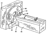
本発明の一実施形態では、計算機式断層写真法画像を用いる。図1及び図2には、計算機式断層写真(CT)イメージング・システム10が、「第3世代」CTスキャナに典型的なガントリ12を含むものとして示されている。ガントリ12はX線源14を有しており、X線源14は、X線ビーム16をガントリ12の対向する側に設けられている検出器アレイ18に向かって投射する。検出器アレイ18は検出器素子20によって形成されており、検出器素子20は一括で、患者22等の物体を透過する投射X線を感知する。各々の検出器素子20が、入射X線ビームの強度を表わし従って物体又は患者22を透過する際のビームの減弱を表わす電気信号を発生する。X線投影データを取得するための一回の走査の間に、ガントリ12及びガントリ12に装着されている構成部品は、回転中心24の周りを回転する。一実施形態では、図2に示すように、検出器素子20は、一回の走査の間に単一の画像スライスに対応する投影データが取得されるように一行に配列されている。もう一つの実施形態では、検出器素子20は複数の平行な行を成して配列されているので、一回の走査の間に複数の平行なスライスに対応する投影データを同時に得ることができる。
【0011】
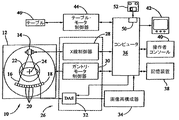
ガントリ12の回転及びX線源14の動作は、CTシステム10の制御機構26によって制御されている。制御機構26はX線制御器28とガントリ・モータ制御器30とを含んでおり、X線制御器28はX線源14に電力信号及びタイミング信号を供給し、ガントリ・モータ制御器30はガントリ12の回転速度及び位置を制御する。制御機構26内に設けられているデータ取得システム(DAS)32が検出器素子20からのアナログ・データをサンプリングして、後続の処理のためにこのデータをディジタル信号へ変換する。画像再構成器34が、サンプリングされてディジタル化されたX線データをDAS32から受け取って高速画像再構成を実行する。再構成された画像はコンピュータ36への入力として印加され、コンピュータ36は大容量記憶装置38に画像を記憶させる。
【0012】
コンピュータ36はまた、キーボードを有するコンソール40を介して操作者から指令及び走査用パラメータを受け取る。液晶表示器(LCD)及び陰極線管のような付設されている表示器42によって、操作者は再構成された画像及びコンピュータ36からのその他のデータを観測することができる。操作者が供給した指令及びパラメータはコンピュータ36によって用いられて、DAS32、X線制御器28及びガントリ・モータ制御器30に制御信号及び情報を供給する。加えて、コンピュータ36は、モータ式テーブル46を制御するテーブル・モータ制御器44を動作させて、患者22をガントリ12内で配置する。具体的には、テーブル46は患者22の各部分をガントリ開口48を通して移動させる。コンピュータ36、コンソール40、及び表示器42は、以下に述べる方法においてポインティング・デバイス及びキーボードと共に用いられる。ポインティング・デバイスは例えば、コンソール40上に設けられている制御器、又はマウスのような別個の装置(図示されていない)である。
【0013】
一実施形態では、コンピュータ36は着脱式媒体52に読み書きを行なう装置50を含んでいる。例えば、装置50はフロッピー(商標)・ディスク・ドライブ、CD−R/Wドライブ又はDVDドライブである。これに対応して、媒体52は、フロッピー(商標)・ディスク、コンパクト・ディスク又はDVDとなる。一実施形態では、装置50及び媒体52を用いて、イメージング・システム10から他のコンピュータへ取得された投影データを転送してさらなる処理を行ない、或いは他の実施形態では、コンピュータ36によって処理される機械読み取り可能な命令を入力する。
【0014】
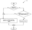
図3は、患者22(図1に示す)の管構造を解析する方法60の実施形態の一例の流れ図である。方法60は、1以上の検査において、結腸のような管構造の中心線に沿って1以上のカーソルをガイドする方法を記述している。カーソルは三次元位置を示す視覚的標識であり、利用者によって三次元ビュー及び再編成済スライスのような管構造の内部の選択された位置に配置されてよい。方法60は、カーソル位置の周囲で管構造の中心線である局所的経路を算出することを容易にする。カーソルの位置は三次元ビューに表示される。次いで、カーソルを含むアキシャル・スライス、サジタル・スライス、コロナル・スライス及び斜方スライスを表示することができる。さらに、ビューを回転させる場合には、カレントのカーソル位置における接平面から構造の中心線までの角度を記憶して、新たな接平面から同じ角度でさらに内部三次元ビューを表示するようにし、これにより、構造に対して同じ配向を保持する。
【0015】
方法60は、患者の管構造を表わす表示管構造の内部でカーソル第一の位置を受け取る工程62と、管構造内で経路を決定する工程64と、カーソル第二の位置まで所定の方向に所定の距離だけ経路に沿ってカーソルを移動させる工程66とを含んでいる。方法60はまた、カーソル第二の位置を示す三次元ビュー、並びにカーソル第二の位置を示すアキシャル・スライス、サジタル・スライス、コロナル・スライス、及び1以上の斜方スライスの1以上を表示する工程を含んでいる。尚、斜方スライスはカーソル第二の位置において管構造に垂直とする。方法60はまた、カーソル第二の位置からの内部三次元ビューを表示する工程を含んでおり、ここで内部ビューは「内視鏡様」ビューである。
【0016】
カーソル第一の位置を受け取る工程62は、第一のカーソル位置を入力する工程と、第一のカーソル位置が管構造の内部に位置するか否かを判定する工程と、コンピュータ36にインストールされているコンピュータ・プログラムを初期化する工程とを含んでいる。
【0017】
利用時には、操作者がコンピュータ36に、管構造内のカーソル第一の位置、及び操作者が検査したい管構造に沿った方向を入力する。一実施形態では、カーソル第一の位置は、操作者がポインティング・デバイスを用いることにより入力され、また方向は、操作者が前方矢印キー及び後方矢印キー等であるがこれらに限定されないキーボード上の1以上のキーを押すことにより入力される。もう一つの実施形態では、カーソル第一の位置及び方向は、操作者が他の従来のデータ入力方法を用いることにより入力される。コンピュータ36は操作者入力を受け取って、カレントのカーソル位置の値(CtxCurPos)及びベクトル方向成分(CtxMoveDir)を含む三次元ベクトルを生成する。カーソル第一の位置はCtxCurPosとして割り当てられ、すなわち表示器42に表示されている例えば結腸(図示されていない)のような三次元管構造の内部に位置するカレントのカーソル位置として割り当てられる。コンピュータは、利用者が選択した方向入力をCtxMoveDirとして割り当て、すなわちコンピュータ36は、CtxCurPosに原点を有しCtxMoveDirの方向にある三次元ベクトルを生成する。加えて、コンピュータ36はCtxCurPosにグレイ・レベル値(Val)を割り当てる。コンピュータ36は受け取ったカーソル位置にのみ基づいてベクトルを生成する。すなわちコンピュータ36は受け取った始点及び受け取った終点の両方を用いてベクトル(すなわち経路)を算出するのではない。そうではなく、コンピュータ36はベクトルに従って終点を決定する。
【0018】
次いで、コンピュータ36はカーソルが管構造内に位置するか否かを判定する。CtxCurPosに割り当てられているグレイ・レベル値が、管構造を画定する最小ボクセル値(CtxMinVoxelValue)と管構造を画定する最大ボクセル値(CtxMaxVoxelValue)との間にある、すなわちCtxMinVoxelValue<CtxCurPos<CtxMaxVoxelValueであるならば、コンピュータ36はコンピュータ36にインストールされているプログラムを初期化する工程に進む。或いは、CtxCurPosがCtxMinVoxelValueとCtxMaxVoxelValueとの間にないならば、コンピュータ36は不正の出力を生成して、操作者にCtxCurPos及びCtxMoveDirを入力し直すように要求する。次いで、コンピュータ36は、コンピュータ36にインストールされているプログラムが初期化されているか否かを判定する。プログラムが初期化されていたならばコンピュータ36は方法60を続行し、プログラムが初期化されていないならばコンピュータ36はプログラムを初期化して方法60を続行する。
【0019】
図4は、コンピュータ36を初期化する工程70を含む方法60の一部を示す流れ図である。コンピュータ36を初期化する工程70は、管構造内で複数の候補ボクセルを選択する工程と、複数の候補ボクセルを連結する工程とを含んでいる。
【0020】
利用時には、管構造内で複数の候補ボクセルを選択する工程は、初期グレイ・レベル空間にある候補ボクセルに閾値を適用する工程すなわち管構造を画定する工程と、管構造以外を除去して管構造内に位置していないすべての点を消去する工程とを含んでいる。選択されないボクセルが、以降で記載する計算工程のいずれにも用いられなければ初期化70は有効である。或いは、初期化70は具現化形態に依存しており、操作者が迂回させてもよい。一実施形態では、操作者は二つのピクセルの三次元膨張を適用することにより管構造の境界を視覚化することができる。
【0021】
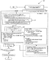
図5は、管構造内で経路を決定する工程64を含む方法60の一部を示す流れ図であり、工程64は、新たな軌跡を決定する工程72と、軌跡内でNextPoint点を得る工程74とを含んでいる。軌跡を決定する工程72は、コンテクストを初期化する工程と、カレントのCtxCurPosを用いて新たな軌跡を開始する工程と、初期探索方向を設定する工程とを含んでいる。
【0022】
コンピュータ36は先ず、軌跡コンテクスト(CtxTraj)が空であるか、又はCtxCurPosが手動で移動させられたかを判定する。CtxTrajは、方向情報を有する点の二重連鎖リストである。CtxTrajが空でなく、且つCtxCurPosが手動で移動させられていなければ、コンピュータ36は方法60を続行して、次の点(NextPoint)を得る工程74に進む。CtxTrajが空であるか又はCtxCurPosが手動で移動させられていたならば、コンピュータ36は管構造内で新たな経路を決定する。
【0023】
利用時には、コンピュータ36は軌跡点リストを空にして、カレントのCtxCurPosを軌跡に加え、すなわちCtxCurPoint=CtxCurPosと設定する。コンピュータ36は軌跡終点をロック解除して、コンピュータ36が追加点を加えられるようにする。軌跡終点をロックしていると、コンピュータ36は追加軌跡点を入力することが禁止される。次いで、コンピュータ36は回転行列(CtxRelativeRotMat)=三次元単位行列と設定する。CtxRelativeRotMatはコンピュータ36によって用いられて、本書に記載するようにCtxCurPosを用いてCtxMoveDirの方向で初期探索方向を得る。一実施形態では、x及びyの回転すなわち二次元画面座標を用いて三次元回転行列を生成する。次いで、コンピュータ36は、予め定義されている管構造の位相幾何学的特徴が利用可能であるか否かを判定する。コンピュータ36は初期探索方向を決定し、すなわち図5に従って前方(FwDir)又は後方(BkDir)を決定する。
【0024】
図6は、NexPoint点を得る工程74を含む方法60の一部を示す流れ図である。NextPoint点を得る工程74は、軌跡終点がロックされているか否かを判定する工程を含んでいる。一実施形態では、軌跡終点がロックされているならば、コンピュータ36は、軌跡終点がCtxMoveDirの方向に前方3点未満に位置するか否かを判定し、軌跡終点が移動方向に前方3点未満に位置するならば、コンピュータ36は次の点(NextPoint)をヌルに設定して続行する。軌跡終点がロックされており、且つ軌跡点がCtxMoveDirの方向に前方3点未満に位置していないならば、コンピュータ36はNextPointをCtxMoveDirの方向にCtxCurPointに続く軌跡点に等しく設定して、プログラムを続行する。或いは、軌跡終点がロックされていないならば、コンピュータ36はNextPointをCtxMoveDirの方向にCtxCurPointに続く軌跡点に等しく設定する。目標の軌跡が軌跡終点から3点未満に位置する場合に軌跡を再計算するようにすると、軌跡が管構造の中心に近接した状態に留まることを保証することが容易になる。
【0025】
ここで図3を再び参照すると、コンピュータ36は次いで、CtxTrajがロックされておらず、且つNextPointがヌルに等しいことを確認する。Yesである、すなわちCtxTrajがロックされておらず、且つNextPointがヌルに等しいならば、コンピュータ36は後に詳述する大局的アプローチを用いて新たな点を算出する。或いは、コンピュータ36はNextPointに問い合わせてNextPointがヌルに等しいか否かを確認する。Noである、すなわち次の点がヌルに等しくないならば、コンピュータ36は方法60を進める。Yesである、すなわちNextPointがヌルであるならば、前方への進行を停止して、操作者は後方に移動するか又は他の点から開始し直すことができる。或いは、終点まで3点未満のままであるならば軌跡を再計算する。軌跡を再計算すると、軌跡が管構造の中心に近接した状態に留まることを保証することが容易になる。加えて、軌跡(CtxTraj)をロックし且つ/又はNextPointがヌルであるか否かを検査することにより、コンピュータ36は前方又は後方のいずれかへの進行をいつ停止すべきかを判定することができる。
【0026】
図7は、大局的アプローチを用いて新たな点を算出する工程80を含む方法60の一部を示す流れ図である。大局的アプローチを用いて新たな点を算出する工程80は、関心のある球面を設定する工程82と、CtxCurPointまでの距離を算出する工程84と、管構造境界までの距離を算出する工程86と、最遠中心点(FinalPoint)を得る工程88と、CtxCurPointからFinalPoint(すなわち終点)までの最良の経路を算出する工程90とを含んでいる。
【0027】
図8は、関心のある球面を設定する工程82を含む方法60の一部の見取り図である。関心のある球面を設定する工程82は、CtxCurPoint、及びCtxMoveDirの方向に複数の点を含む小空間を選択する工程を含んでいる。ここで、CtxCurPointについてCtxMoveDirの方向にある方向ベクトルを定義する。
【0028】
利用時には、図7及び図8を参照して述べると、操作者はCtxCurPointすなわち三次元点と、DirToGoすなわち三次元ベクトルとを含む小空間を選択する。一実施形態では、球の半径(CtxSphereRadius)は固定されている。DirToGoベクトルが正規化されているならば、CenterofSphereは下記の式に従って決定される。
【0029】
CenterOfSphere=CtxCurPoint+4×(CtxSphereRadius/5)×DirToGo
図7を再び参照すると、次いで、前述の図5に従って空間を再び初期化して、コンピュータ36は以下に記載するようにしてCtxCurPointまでの距離を算出する84ようにプログラムに指示する。
【0030】
図9は、CtxCurPointまでの距離を算出する工程84を含む方法60の一部の流れ図である。利用時には、軌跡上のカレントの点(CtxCurPoint)までの距離を算出する工程84は、すべての点(P)について、距離マップ(DistMap(P))=65535を生成する工程を含んでいる。目標点が与えられているならば、初期値(Initvalue)=65535とする。目標点が与えられていないならば、Initvalue=0とする。次いで、コンピュータ36は前方伝播プログラム及び後方伝播プログラムの少なくとも一方を初期化する。
【0031】
図10は、前方に伝播させる工程92及び後方に伝播させる工程94を含む方法60の一部の流れ図である。伝播方向が前方であるか又は伝播方向が後方であるならば、コンピュータ36は図10に示す方法を実行する。次いで、コンピュータ36は管構造の境界までの距離を算出する。
【0032】
図11は、管構造の境界までの距離を算出する工程86を含む方法60の一部の流れ図である。一実施形態では、コンピュータ36は、CtxCurPointまでの距離を算出するのに用いられたものと同じ方法、すなわち図11に示すような方法を用いて管構造の境界までの距離を算出する。次いで、コンピュータ36は最遠点を得る工程88に進む。
【0033】
図7を再び参照すると、大局的アプローチを用いて新たな点を算出する工程80はまた、最遠点(FinalPoint)を得る工程88を含んでいる。図11は、下記の式に従って最遠点を得る工程88を含む方法60の一部の流れ図である。
【0034】
Dmin=CtxCurPointまでの最短距離
Dmax=CtxCurPointまでの最長距離
Dfar=[(4×Dmax)+(1×Dmin)]/5
ここで、CtxCurPointまでの距離(D())及び管構造の境界までの距離は、前述の距離マップを用いて決定される。
【0035】
最遠中心点(FinalPoint)を得る工程はまた、「候補」=D(CtxCurPoint,P)>Dfarとなるような点Pと設定する工程を含んでいる。次いで、FinalPointを、FinalPoint=管構造の境界までの距離が最大の「候補」に含まれる点、に従って算出する。
【0036】
図12は、CtxCurPointからFinalPointまでの最良の経路を算出する工程90(図7に示す)を含む方法60の一部の流れ図であり、工程90は、図13に示すように、距離を前方に伝播させる工程100と距離を後方に伝播させる工程102とを含んでいる。前方に伝播させる工程100及び後方に伝播させる工程102は、第一の線から伝播させる工程104及び第二の線から伝播させる工程106、すなわち線の間での距離伝播と、x軸に沿って伝播させる工程108すなわち線の内部での距離伝播とを含んでいる。第一の線から伝播させる工程104及び第二の線から伝播させる工程106を図14に示す。x軸に沿って伝播させる工程108を図15に示す。
【0037】
図12〜図15に示すように、下記に従ってcost()関数を構築する。
【0038】
Cost(Pn+1)=Minimum(Cost(Pn+1),Cost(Pn)+V(Pn+1))
ここで、nは構築経路に沿った段階であり、Pnは段階nにおける点を表わしており、V(Pn)は対応する点から管の境界までの距離であり、経路は所与のボクセルの六つの面に沿って位置している。非等方的なボクセルについては、ボクセルの六つの面は平行六面体を形成する。等方的なボクセルについては、ボクセルの六つの面は立方体を形成する。
【0039】
この関数を用いて、逐次的工程を適用して最終の結果を算出する。cost(0)における点0すなわち始点から開始する。他のすべての点は有限のcost()を有する。次いで、線の内部で左の点又は右の点まで値を伝播させ、次いで線を横断してy,zからy+1又はz+1の線まで前方に進める。次いで、工程をy,zからy−1又はz−1の線まで他方の方向に繰り返す。一旦、伝播した「波」が目標点に到達したら所与の最大繰り返し回数の後に工程を停止する。最良の直前点までの方向符号を値と共に記憶する。
【0040】
性能を高めるために、アクティブ線の配列も用いる。配列は各々の線毎に2ビット語を含んでおり、新たな値が所与の線に割り当てられた直後に2からデクリメントし、次いで、線が前方及び後方の二回処理された後に0となり、値には一切変更を加えない。この配列を用いて、伝播工程によって到達しなかった線又は収束した線をスキップする。
【0041】
この工程は、フィードバック機能を用いて操作者が中止させてもよい。また、スケーリング特徴を設けて、オーバフローを防ぐ(雑音の多い物体の極めて長い経路についてcos(t)を13ビット値に記憶させる)。オーバフローは、目標に達したことを検出するのに失敗したことになる。このことは報告され、誤った識別結果に帰すことがないようにする。最良の経路は、目標点から初期シードまでの方向符号を展開することにより算出される。
【0042】
図3を再び参照すると、一旦、コンピュータ36が大局的アプローチを用いて新たな点を算出する工程80を完了したら、コンピュータ36は管構造の転回部(half turn)について検査する。図16は、管構造の転回部について検査する工程110を含む方法60の一部を示している。図17は、管構造の転回部について検査する工程100の例図である。転回部について検査する工程110は、軌跡を検査して軌跡が図17に示すような転回部又はループを含んでいるか否かを確認して、転回部又はループのいずれかが検出されたならば軌跡を切断する。
【0043】
コンピュータ36が転回部について検査する工程110を完了した後に、コンピュータ36は前述したような軌跡内でNextPoint点を得る工程74に戻る。NextPointがヌルでないならば、コンピュータ36は後述のようにしてNextPointに向かって移動する。NextPointがヌルであるならば、コンピュータ36は局所的アプローチを用いて新たな点を算出する。
【0044】
図18は、局所的アプローチを用いて新たな点を算出する工程120を示す流れ図である。局所的アプローチを用いて新たな点を算出する工程120は、CtxMoveDirの方向でCtxCurPointに続く軌跡点を削除する工程と、PrevPoint及びCtxMoveDirについてベクトル・データを算出する工程122と、Point及びCtxMoveDirについてベクトル・データを算出する工程124とを含んでいる。
【0045】
図19及び図20は、局所的アプローチを用いて新たな点を算出する工程120の方法を示す見取り図である。局所的アプローチは、連結点が存在しないすなわち唯一の枝しか存在しない、管の直径の変化が「十分に」平滑である、及び転回が滑らかである等の管の位相幾何学的特徴に対する仮定に基づいている。従って、局所的アプローチを用いて、所与の点において、前方半平面の方向にベクトルを投射(レイ・キャスティング)する。管の境界に位置するベクトルの終点及びベクトルの長さをコンピュータ36に記憶させる。一実施形態では、得られる方向ベクトルは、ある方向で境界が遠いほど得られるベクトルに当該方向が大きな寄与をするように、ベクトルの長さによって重み付けした(ponderated)投射ベクトルの和となり、これが通例の場合である。投射ベクトルの平均長に減少が検出される場合には、直進前方に直径の減少が存在する。次いで、長いベクトルにはより多くの加重を与えて、「視角」を収縮させて転回部を回避すると、得られるベクトルは、ベクトルの長さの羃で重み付けされた投射ベクトルから選択したベクトル(視角に含まれるもの)の和となる(減少が急速であるほど羃が大きくなるようにしている)。これが、得られるベクトルを強制的に管内で最も長い投射ベクトルとする手段である。
【0046】
図3を再び参照すると、局所的アプローチを用いて新たな点を算出する工程120の後に、コンピュータ36は前述のような転回部について検査する工程110を開始する。次いで、コンピュータ36は、前述のような次の点を得る工程74を開始する。そして、コンピュータ36はNextPoint=ヌルであるか否かを検査する。NextPointがヌルに等しければ、コンピュータ36はプログラムを終了させる。NextPointがヌルに等しくなければ、コンピュータ36はNextPointに向かって移動させる工程66を開始する。
【0047】
図21は、次の点(NextPoint)に向かって移動させる工程66を含む方法60の一部である。軌跡コンテクストにおいてカレントの点及び次の点が与えられ、またカレントのカーソル位置が与えられると、コンピュータ36は図21に従って新たなカーソル位置を算出する。
【0048】
図22は、視線方向を算出する工程130を含む方法60の一部である。一旦、軌跡コンテクスト及びカレントのカーソル位置が決定されたら、図22に従って視線方向を算出する工程130が開始する。利用時には、操作者がカーソルを移動させると、新たな軌跡が開始して、相対回転行列が再初期化される。さらに、操作者が内視鏡ビューの配向を変更する度毎に、相対回転行列を算出して、追跡されている軌跡に対してビューが同じ角度を保つようにする。
【0049】
一実施形態では、方法60は、検査時に管構造に沿って操作者をガイドすることを促進する。さらに、方法60はローカル計算に頼っているので、設定時間の短縮を促進する。方法60はまた、始点及び終点の画定を回避しているため、操作者が検査を行なうのに必要な時間を短縮する。加えて、同じ構造について多数回の取得を行なう場合には、すべてのデータ集合について同じ始点が正確に識別され、従ってすべてのカーソルが構造の中心線に沿って同じ距離を走行するので、カーソルは当該構造内の同じ位置を識別するものとなる。この場合に要求される利用者入力は、全検査についての始点の画定のみである。
【0050】
もう一つの実施形態では、時間の経過にわたって管構造を再視覚化する方法200が、同じ管構造を表わす少なくとも第一の時刻での第一の三次元データ集合及び第二の時刻での第二の三次元データ集合を形成する工程202を含んでいる。方法200は、患者の検査時に、操作者がコンピュータ36において同時に前回の検査の結果と現在の検査の結果とを比較して、これらの結果の差に基づいて処置を調整することを可能にすることにより、操作者を支援することを促進する。方法200はまた、第一の三次元データ集合の第一のビュー及び第二の三次元データ集合の第二のビューを生成する工程204と、第一のビュー内で第一の三次元位置に第一のカーソルを配置すると共に、第二のビュー内で第一の三次元位置に第二のカーソルを配置する工程206とを含んでいる。方法200はまた、第一の管構造及び第二の管構造内で経路を決定する工程208と、第一のビュー及び第二のビューの少なくとも一方においてカーソル位置からの方向を画定する工程210と、第一のカーソル第二の位置まで所定の方向に所定の距離だけ上述の決定した経路に沿って第一のカーソルを移動させると共に、第二のカーソル第二の位置まで所定の方向に所定の距離だけ上述の決定した経路に沿って第二のカーソルを移動させる工程212とを含んでいる。
【0051】
方法200はまた、第一のカーソル第二の位置を示す三次元ビュー、第一のカーソル第二の位置を示すアキシャル・ビュー、第一のカーソル第二の位置を示すサジタル・ビュー、第一のカーソル第二の位置を示すコロナル・ビュー、及び第一のカーソル第二の位置を示す1以上の斜方スライスの1以上を表示する工程220と、第一のカーソル第二の位置及び第二のカーソル第二の位置の少なくとも一方からの内部三次元ビューを表示する工程222とを含んでいる。方法200はさらに、方向入力を受け取って、第一のカーソル及び第二のカーソルの少なくとも一方を受け取った方向入力に従って所定の経路に沿って所定の距離だけ移動させる工程224と、それぞれのカーソル第二の位置において管構造の軸に沿った方向に向けて第一のカーソル第二の位置及び第二のカーソル第二の位置の少なくとも一方からの管構造の1以上の内部三次元ビューを表示する工程226とを含んでいる。
【0052】
本発明の実施形態は、脈管構造、冠状動脈及び気管を含めた多くの形式の管構造の選択及び解析に応用可能である。加えて、本発明の実施形態をCTイメージング・システム10と共に説明したが、本発明は他の形式のイメージング・システム及びかかるシステムから得られた画像にも同様に適用可能であることが理解されよう。本発明の他の実施形態に用いられるかかる他の形式のイメージング・システムの実例には、MRイメージング・システム、及び3DX線イメージング・システムがある。加えて、本発明の幾つかの実施形態は、それ自体ではいずれのイメージング・システムの一部でもないデータ・コンピュータ及び表示器を用いている。これらの場合には、テープ、ディスク若しくは他の記憶媒体、又はネットワーク等を介してコンピュータが1以上の別個のイメージング・システムからデータを得る。1以上のかかる実施形態が、1よりも多い形式のイメージング・システムからデータを受け取り、操作して処理するように構成される。
【0053】
本書に記載した方法は、計算機式断層写真法システムの例におけるものであるが、これらの方法は計算機式断層写真法システムによって実施されることに限定されておらず、多くの異なる撮像モダリティで用いることができる。例えば、これらの方法をX線、磁気共鳴、陽電子放出断層写真法、超音波、及び他の撮像モダリティと共に用いることができる。
【0054】
様々な特定の実施形態によって本発明を説明したが、当業者であれば、特許請求の範囲の要旨及び範囲に含まれる改変を施して本発明を実施し得ることを理解されよう。
【図面の簡単な説明】
【図1】CTイメージング・システムの見取り図である。
【図2】図1に示すシステムのブロック概略図である。
【図3】患者の管構造を解析する方法の実施形態の一例の流れ図である。
【図4】管構造を解析する図3に示す方法の一部の図である。
【図5】管構造を解析する図3に示す方法の一部の図である。
【図6】管構造を解析する図3に示す方法の一部の図である。
【図7】管構造を解析する図3に示す方法の一部の図である。
【図8】管構造を解析する図3に示す方法の一部の図である。
【図9】管構造を解析する図3に示す方法の一部の図である。
【図10】管構造を解析する図3に示す方法の一部の図である。
【図11】管構造を解析する図3に示す方法の一部の図である。
【図12】管構造を解析する図3に示す方法の一部の図である。
【図13】管構造を解析する図3に示す方法の一部の図である。
【図14】管構造を解析する図3に示す方法の一部の図である。
【図15】管構造を解析する図3に示す方法の一部の図である。
【図16】管構造を解析する図3に示す方法の一部の図である。
【図17】管構造を解析する図3に示す方法の一部の図である。
【図18】管構造を解析する図3に示す方法の一部の図である。
【図19】管構造を解析する図3に示す方法の一部の図である。
【図20】管構造を解析する図3に示す方法の一部の図である。
【図21】管構造を解析する図3に示す方法の一部の図である。
【図22】管構造を解析する図3に示す方法の一部の図である。
【符号の説明】
10 CTシステム
12 ガントリ
14 X線源
16 X線ビーム
18 検出器アレイ
20 検出器素子
22 患者
24 回転中心
26 制御機構
42 表示器
46 モータ式テーブル
48 ガントリ開口
50 読み書き装置
52 着脱式媒体
60 患者の管構造を解析する方法
62 患者の管構造を表わす表示管構造の内部でカーソル第一の位置を受け取る工程
64 管構造内で経路を決定する工程
66 カーソル第二の位置まで所定の方向に所定の距離だけ経路に沿ってカーソルを移動させる工程
120 局所的アプローチを用いて新たな点を算出する工程[0001]
BACKGROUND OF THE INVENTION
The present invention relates generally to a method and apparatus for analyzing blood vessel images, and more particularly to radiation during radiological examination with images obtained from computed tomography imaging, MR imaging, and 3D radiographic imaging. The present invention relates to a method and apparatus for assisting medical personnel, such as a physician, to prepare measurements and reports.
[0002]
In at least some computed tomography (CT) imaging system configurations, the x-ray source projects a fan-shaped beam, which is the XY plane of a Cartesian coordinate system, generally “ It is collimated to lie in a plane called the “imaging plane”. The X-ray beam passes through an object to be imaged such as a patient. The beam is incident on the array of radiation detectors after being attenuated by the object. The intensity of the attenuated beam radiation received by the detector array depends on the amount of attenuation of the X-ray beam by the object. Each detector element in the array produces a separate electrical signal that is a measurement of beam attenuation at the detector location. Attenuation measurements from all detectors are acquired separately to form a transmission profile (cross section).
[0003]
In known third generation CT systems, the x-ray source and detector array rotate with the gantry around the object to be imaged in the imaging plane so that the angle at which the x-ray beam intersects the object constantly changes. An x-ray source typically includes an x-ray tube that emits an x-ray beam at a focal point. The X-ray detector typically includes a collimator that collimates the X-ray beam received by the detector, a scintillator provided adjacent to the collimator, and a photodetector provided adjacent to the scintillator. Yes.
[0004]
One application of computed tomography (CT) imaging and magnetic resonance (MR) imaging and 3DX ray imaging (3DXR) is tube analysis. X-ray quantification and analysis of vascular pathology is important for radiologists who are required to quantify length, cross-sectional dimensions, angles, and related parameters to evaluate stenosis or aneurysm parameters. Some known imaging systems perform vascular pathology analysis using three-dimensional data such as CT, MR or 3DXR.
[Patent Document 1]
US Pat. No. 5630034
[0005]
[Problems to be solved by the invention]
Visual pathology analysis can be difficult because the operator must track structures that may be bending. The imaging system described above can include a method for locating the path between the start and end points, so that the operator can calculate with the help of a simple interface device such as a slider or scroll bar Although tracking is performed along the route, this method may increase the computer time required to define and calculate the route. In addition, if there are occluded or discontinuous paths, additional steps may be required to visualize the structure.
[0006]
[Means for Solving the Problems]
In one embodiment, a method for analyzing a patient's tube structure is provided. The method includes receiving a cursor first position within a display tube structure representing a patient's tube structure, determining a path within the tube structure based only on the received cursor first position, Moving the cursor along a path in a predetermined direction to a second position in a predetermined direction.
[0007]
In another embodiment, a method for redisplaying a tube structure over time is provided. The method includes forming a first three-dimensional data set at least at a first time and a second three-dimensional data set at a second time representing the same tube structure; Forming a first view and a second view of a second three-dimensional data set, placing a first cursor at a first three-dimensional position in the first view, and Placing a second cursor at a first three-dimensional position in a second view corresponding to the first cursor position at. The method also includes determining a path in the tube structure, defining a direction from the cursor position in at least one of the first view and the second view, and predetermined to the second position of the first cursor. The first cursor is moved along the determined path by a predetermined distance in the direction of and the second cursor is moved along the determined path by the predetermined distance in the predetermined direction to the second position of the second cursor. Moving the second cursor.
[0008]
In yet another embodiment, a computer readable medium encoded with a computer executable program for analyzing a patient's tubule structure is provided. The program receives a cursor first position within the display tube structure representing the patient's tube structure and determines a path within the tube structure based on the received cursor first position, where the path determined is It includes an end point to be determined, and is configured to instruct the computer to move the cursor along a path in a predetermined direction to a second position of the cursor along a predetermined distance.
[0009]
In yet another embodiment, a medical imaging system for analyzing patient tube structure is provided. The medical imaging system includes a detector array, one or more radiation sources, and a computer coupled to the detector array and the radiation sources. The computer receives the cursor first position within the display tube structure representing the patient tube structure, determines a path including the end point within the tube structure based on the received cursor first position, and the cursor second position. The cursor is moved along a route by a predetermined distance in a predetermined direction.
[0010]
DETAILED DESCRIPTION OF THE INVENTION
In one embodiment of the present invention, computed tomography images are used. 1 and 2, a computed tomography (CT)
[0011]
The rotation of the
[0012]
The
[0013]
In one embodiment,
[0014]
FIG. 3 is a flow diagram of an example embodiment of a method 60 for analyzing the tube structure of a patient 22 (shown in FIG. 1). Method 60 describes a method of guiding one or more cursors along the centerline of a tubular structure such as the colon in one or more examinations. The cursor is a visual indicator that indicates a three-dimensional position and may be placed by the user at a selected position within the tube structure, such as a three-dimensional view and a reorganized slice. Method 60 facilitates calculating a local path that is the centerline of the tube structure around the cursor position. The cursor position is displayed in the 3D view. The axial slice, sagittal slice, coronal slice and oblique slice containing the cursor can then be displayed. Furthermore, when rotating the view, the angle from the tangent plane at the current cursor position to the centerline of the structure is stored, and the internal 3D view is displayed at the same angle from the new tangent plane. Keeps the same orientation to the structure.
[0015]
The method 60 includes receiving 62 a cursor first position within a display tube structure representing the patient's tube structure, determining a
[0016]
[0017]
At the time of use, the operator inputs to the
[0018]
[0019]
FIG. 4 is a flow diagram illustrating a portion of a method 60 that includes the
[0020]
In use, selecting a plurality of candidate voxels within the tube structure includes applying a threshold to the candidate voxels in the initial gray level space, i.e., defining the tube structure, and removing other than the tube structure. Erasing all points not located within.
[0021]
FIG. 5 is a flow diagram illustrating a portion of a method 60 that includes the
[0022]
The
[0023]
At the time of use, the
[0024]
FIG. 6 is a flow diagram illustrating a portion of a method 60 that includes the
[0025]
Referring now again to FIG. 3,
[0026]
FIG. 7 is a flow diagram illustrating a portion of a method 60 that includes the
[0027]
FIG. 8 is a sketch of a portion of a method 60 that includes setting 82 a sphere of interest. Setting 82 the sphere of interest includes selecting a small space that includes a plurality of points in the direction of CtxCurPoint and CtxMoveDir. Here, a direction vector in the direction of CtxMoveDir is defined for CtxCurPoint.
[0028]
In use, as described with reference to FIGS. 7 and 8, the operator selects a small space containing CtxCurPoint, ie, a three-dimensional point, and DirToGo, ie, a three-dimensional vector. In one embodiment, the radius of the sphere (CtxSphereRadius) is fixed. If the DirToGo vector is normalized, CenterofSphere is determined according to the following equation:
[0029]
CenterOfSphere = CtxCurPoint + 4 × (CtxSphereRadius / 5) × DirToGo
Referring again to FIG. 7, the space is then reinitialized according to FIG. 5 above, and the
[0030]
FIG. 9 is a flow diagram of a portion of a method 60 that includes a
[0031]
FIG. 10 is a flow diagram of a portion of a method 60 that includes a
[0032]
FIG. 11 is a flow diagram of a portion of a method 60 that includes a
[0033]
Referring back to FIG. 7, step 80 of calculating a new point using a global approach also includes
[0034]
Dmin = shortest distance to CtxCurPoint
Dmax = longest distance to CtxCurPoint
Dfar = [(4 × Dmax) + (1 × Dmin)] / 5
Here, the distance to the CtxCurPoint (D ()) and the distance to the boundary of the tube structure are determined using the above-described distance map.
[0035]
The step of obtaining the farthest center point (FinalPoint) also includes the step of setting the point P such that “candidate” = D (CtxCurPoint, P)> Dfar. Then, FinalPoint is calculated according to FinalPoint = the point included in the “candidate” having the maximum distance to the boundary of the tube structure.
[0036]
FIG. 12 is a flow diagram of a portion of a method 60 that includes a step 90 (shown in FIG. 7) that calculates the best path from CtxCurPoint to FinalPoint, where
[0037]
As shown in FIGS. 12 to 15, the cost () function is constructed according to the following.
[0038]
Cost (P n + 1 ) = Minimum (Cost (P n + 1 ), Cost (P n ) + V (P n + 1 ))
Where n is a stage along the construction path and P n Represents the point at stage n and V (P n ) Is the distance from the corresponding point to the tube boundary, and the path is located along the six faces of a given voxel. For anisotropic voxels, the six faces of the voxel form a parallelepiped. For isotropic voxels, the six faces of the voxel form a cube.
[0039]
Using this function, a sequential process is applied to calculate the final result. Start at
[0040]
An active line array is also used to enhance performance. The array contains a 2-bit word for each line, decrements from 2 immediately after a new value is assigned to a given line, then becomes 0 after the line has been processed twice, forward and backward. , Do not make any changes to the values. This array is used to skip lines that have not been reached or converged by the propagation process.
[0041]
This step may be stopped by the operator using a feedback function. A scaling feature is also provided to prevent overflow (cos (t) is stored as a 13-bit value for very long paths of noisy objects). Overflow will have failed to detect that the goal has been reached. This is reported and should not be attributed to incorrect identification results. The best path is calculated by developing the direction code from the target point to the initial seed.
[0042]
Referring again to FIG. 3, once the
[0043]
After the
[0044]
FIG. 18 is a flow
[0045]
19 and 20 are sketches illustrating the method of
[0046]
Referring again to FIG. 3, after
[0047]
FIG. 21 is a portion of a method 60 that includes a
[0048]
FIG. 22 is a portion of a method 60 that includes the
[0049]
In one embodiment, the method 60 facilitates guiding the operator along the tube structure during inspection. Furthermore, since method 60 relies on local computation, it facilitates a reduction in setup time. Method 60 also avoids defining start and end points, thus reducing the time required for the operator to perform the inspection. In addition, if multiple acquisitions are made for the same structure, the same starting point is accurately identified for all data sets, and therefore all cursors travel the same distance along the structure centerline, so the cursor It will identify the same location in the structure. The only user input required in this case is to define the starting point for all examinations.
[0050]
In another embodiment, a method 200 for re-visualizing a tube structure over time includes a first three-dimensional data set at least at a first time representing the same tube structure and a second at a second time. Forming a three-dimensional data set. The method 200 allows the operator to simultaneously compare the results of the previous test and the current test at the
[0051]
The method 200 also includes a three-dimensional view showing the first cursor second position, an axial view showing the first cursor second position, a sagittal view showing the first cursor second position, Displaying a coronal view indicating a cursor second position and one or more of one or more oblique slices indicating a first cursor second position; and a first cursor second position and a second cursor Displaying 222 an internal three-dimensional view from at least one of the cursor second positions. The method 200 further includes a step 224 of receiving a direction input and moving at least one of the first cursor and the second cursor along a predetermined path according to the received direction input by a predetermined distance; Displaying one or more internal three-dimensional views of the tube structure from at least one of the first cursor second position and the second cursor second position in a direction along the axis of the tube structure at the position of 226.
[0052]
Embodiments of the present invention are applicable to the selection and analysis of many types of vascular structures including vasculature, coronary arteries and trachea. In addition, although embodiments of the present invention have been described in conjunction with
[0053]
The methods described in this document are in the example of a computed tomography system, but these methods are not limited to being performed by a computed tomography system and are used in many different imaging modalities. be able to. For example, these methods can be used with X-ray, magnetic resonance, positron emission tomography, ultrasound, and other imaging modalities.
[0054]
While the invention has been described in terms of various specific embodiments, those skilled in the art will recognize that the invention can be practiced with modification within the spirit and scope of the claims.
[Brief description of the drawings]
FIG. 1 is a sketch of a CT imaging system.
FIG. 2 is a block schematic diagram of the system shown in FIG. 1;
FIG. 3 is a flow diagram of an example embodiment of a method for analyzing a patient's tube structure.
4 is a diagram of a portion of the method shown in FIG. 3 for analyzing tube structure.
FIG. 5 is a diagram of a portion of the method shown in FIG. 3 for analyzing tube structure.
6 is a diagram of a portion of the method shown in FIG. 3 for analyzing tube structure.
7 is a diagram of a portion of the method shown in FIG. 3 for analyzing tube structure.
8 is a diagram of a portion of the method shown in FIG. 3 for analyzing tube structure.
9 is a diagram of a portion of the method shown in FIG. 3 for analyzing tube structure.
FIG. 10 is a diagram of a portion of the method shown in FIG. 3 for analyzing tube structure.
11 is a diagram of a portion of the method shown in FIG. 3 for analyzing tube structure.
12 is a diagram of a portion of the method shown in FIG. 3 for analyzing tube structure.
13 is a diagram of a portion of the method shown in FIG. 3 for analyzing tube structure.
14 is a diagram of a portion of the method shown in FIG. 3 for analyzing tube structure.
15 is a diagram of a portion of the method shown in FIG. 3 for analyzing tube structure.
16 is a diagram of a portion of the method shown in FIG. 3 for analyzing tube structure.
FIG. 17 is a diagram of a portion of the method shown in FIG. 3 for analyzing tube structure.
18 is a partial view of the method shown in FIG. 3 for analyzing the tube structure.
19 is a diagram of a portion of the method shown in FIG. 3 for analyzing tube structure.
20 is a diagram of a portion of the method shown in FIG. 3 for analyzing tube structure.
FIG. 21 is a diagram of a portion of the method shown in FIG. 3 for analyzing tube structure.
22 is a diagram of a portion of the method shown in FIG. 3 for analyzing tube structure.
[Explanation of symbols]
10 CT system
12 Gantry
14 X-ray source
16 X-ray beam
18 Detector array
20 detector elements
22 patients
24 center of rotation
26 Control mechanism
42 Display
46 Motor type table
48 Gantry opening
50 Reading / writing device
52 Removable media
60 Method for analyzing the tube structure of a patient
62. Receiving a cursor first position within a display tube structure representative of a patient tube structure
64 Determining the path in the pipe structure
66 Step of moving the cursor along the path by a predetermined distance in a predetermined direction to the cursor second position
120 calculating a new point using a local approach
Claims (6)
前記患者の前記管構造を表わす表示管構造の内部でカーソル第一の位置を前記コンピュータ(36)が受け取る工程(62)と、
前記管構造に沿った方向を前記コンピュータ(36)が受け取る工程と、
該受け取ったカーソル第一の位置及び該受け取った方向にのみ基づいて前記管構造内で経路を決定する工程(64)と、
カーソル第二の位置まで所定の距離だけ前記経路に沿ってカーソルを移動させる工程(66)とを備え、
前記経路の決定が、初期シード点から目標点に伝播する波であって、1段階毎にいずれかの座標方向に所定単位の距離だけ伝播し、前記波が伝播する前の座標に対応付けられた値に基づいて前記波が伝播した後の座標に対応付けられた値を更新する前記波による最小の値を有する直前点までの複数の方向符号を決定することと、前記目標点から前記初期シード点までの方向符号を展開することにより最良の経路を算出することを含む、方法。A method (60) in which a computer (36) analyzes the tube structure of a patient (22), comprising:
Receiving (62) the computer (36) a first cursor position within a display tube structure representative of the tube structure of the patient;
Receiving the direction along the tube structure by the computer (36) ;
Determining a path within the tube structure based only on the received cursor first position and the received direction;
Moving the cursor along the path by a predetermined distance to the cursor second position (66),
The determination of the path is a wave that propagates from the initial seed point to the target point, propagates by a predetermined unit distance in any coordinate direction for each step, and is associated with the coordinates before the wave propagates. determining a plurality of directions sign until just before the point where the wave based on the value has a minimum value by the wave to update the values associated with the coordinates of the after propagating the said from the target point Calculating a best path by developing a direction code to an initial seed point .
検出器アレイ(18)と、
1以上の放射線源(14)と、
前記検出器アレイ及び前記放射線源に結合されているコンピュータ(36)とを備えており、
該コンピュータ(36)は、
前記患者の前記管構造を表わす表示管構造の内部でカーソル第一の位置を受け取り(62)、
前記管構造に沿った方向を受け取り、
該受け取ったカーソル第一の位置及び該受け取った方向に基づいて前記管構造内で終点を含む経路を決定し(64)、
カーソル第二の位置まで所定の距離だけ前記経路に沿ってカーソルを移動させ(66)、
前記経路の決定を、初期シード点から目標点に伝播する波であって、1段階毎にいずれかの座標方向に所定単位の距離だけ伝播し、前記波が伝播する前の座標に対応付けられた値に基づいて前記波が伝播した後の座標に対応付けられた値を更新する前記波による最小の値を有する直前点までの複数の方向符号を決定することと、前記目標点から前記初期シード点までの方向符号を展開することにより最良の経路を算出することにより行うように構成されている、医用イメージング・システム(10)。A medical imaging system (10) for analyzing the tube structure of a patient (22) comprising:
A detector array (18);
One or more radiation sources (14);
A computer (36) coupled to the detector array and the radiation source;
The computer (36)
Receiving a first cursor position (62) within a display tube structure representative of the tube structure of the patient;
Receiving a direction along the tube structure;
Determining a path including an end point in the tubular structure based on the received first cursor position and the received direction (64);
Move the cursor along the path by a predetermined distance to the second cursor position (66);
The determination of the path is a wave that propagates from the initial seed point to the target point, propagates by a predetermined unit distance in any coordinate direction for each step, and is associated with the coordinates before the wave propagates. determining a plurality of directions sign until just before the point where the wave based on the value has a minimum value by the wave to update the values associated with the coordinates of the after propagating the said from the target point A medical imaging system (10) configured to perform by calculating a best path by developing a direction code to an initial seed point .
Applications Claiming Priority (2)
| Application Number | Priority Date | Filing Date | Title |
|---|---|---|---|
| US10/012954 | 2001-12-10 | ||
| US10/012,954 US6711231B2 (en) | 2001-12-10 | 2001-12-10 | Methods and apparatus to assist and facilitate vessel analysis |
Publications (3)
| Publication Number | Publication Date |
|---|---|
| JP2003225232A JP2003225232A (en) | 2003-08-12 |
| JP2003225232A5 JP2003225232A5 (en) | 2008-07-31 |
| JP4460823B2 true JP4460823B2 (en) | 2010-05-12 |
Family
ID=21757547
Family Applications (1)
| Application Number | Title | Priority Date | Filing Date |
|---|---|---|---|
| JP2002356102A Expired - Fee Related JP4460823B2 (en) | 2001-12-10 | 2002-12-09 | Method and apparatus for supporting and promoting blood vessel analysis |
Country Status (3)
| Country | Link |
|---|---|
| US (1) | US6711231B2 (en) |
| EP (1) | EP1324272A3 (en) |
| JP (1) | JP4460823B2 (en) |
Families Citing this family (13)
| Publication number | Priority date | Publication date | Assignee | Title |
|---|---|---|---|---|
| WO2003094114A1 (en) * | 2002-05-03 | 2003-11-13 | Koninklijke Philips Electronics N.V. | Method of producing and displaying an image of a 3 dimensional volume |
| US7457444B2 (en) * | 2003-05-14 | 2008-11-25 | Siemens Medical Solutions Usa, Inc. | Method and apparatus for fast automatic centerline extraction for virtual endoscopy |
| JP4343723B2 (en) * | 2004-01-30 | 2009-10-14 | オリンパス株式会社 | Insertion support system |
| US7623900B2 (en) * | 2005-09-02 | 2009-11-24 | Toshiba Medical Visualization Systems Europe, Ltd. | Method for navigating a virtual camera along a biological object with a lumen |
| US11275242B1 (en) | 2006-12-28 | 2022-03-15 | Tipping Point Medical Images, Llc | Method and apparatus for performing stereoscopic rotation of a volume on a head display unit |
| US10795457B2 (en) | 2006-12-28 | 2020-10-06 | D3D Technologies, Inc. | Interactive 3D cursor |
| US11315307B1 (en) | 2006-12-28 | 2022-04-26 | Tipping Point Medical Images, Llc | Method and apparatus for performing rotating viewpoints using a head display unit |
| US11228753B1 (en) | 2006-12-28 | 2022-01-18 | Robert Edwin Douglas | Method and apparatus for performing stereoscopic zooming on a head display unit |
| US8934604B2 (en) * | 2007-09-28 | 2015-01-13 | Kabushiki Kaisha Toshiba | Image display apparatus and X-ray diagnostic apparatus |
| DE102008025535B4 (en) * | 2008-05-28 | 2014-11-20 | Siemens Aktiengesellschaft | Method for viewing tubular anatomical structures, in particular vascular structures, in medical 3D image recordings |
| EP2619729B1 (en) * | 2010-09-20 | 2018-07-04 | Koninklijke Philips N.V. | Quantification of a characteristic of a lumen of a tubular structure |
| CN110660059A (en) | 2012-08-13 | 2020-01-07 | 皇家飞利浦有限公司 | Tubular structure tracking |
| EP3796264A1 (en) * | 2019-09-20 | 2021-03-24 | Sandvik Mining and Construction Oy | Modelling of underground worksite |
Family Cites Families (11)
| Publication number | Priority date | Publication date | Assignee | Title |
|---|---|---|---|---|
| JP3483929B2 (en) * | 1994-04-05 | 2004-01-06 | 株式会社日立製作所 | 3D image generation method |
| US6166740A (en) * | 1994-04-15 | 2000-12-26 | Hewlett Packard Company | Method and system for viewing three-dimensional data for a tracked structure |
| US5782762A (en) * | 1994-10-27 | 1998-07-21 | Wake Forest University | Method and system for producing interactive, three-dimensional renderings of selected body organs having hollow lumens to enable simulated movement through the lumen |
| US5920319A (en) | 1994-10-27 | 1999-07-06 | Wake Forest University | Automatic analysis in virtual endoscopy |
| US5611025A (en) * | 1994-11-23 | 1997-03-11 | General Electric Company | Virtual internal cavity inspection system |
| US5882206A (en) * | 1995-03-29 | 1999-03-16 | Gillio; Robert G. | Virtual surgery system |
| US7194117B2 (en) | 1999-06-29 | 2007-03-20 | The Research Foundation Of State University Of New York | System and method for performing a three-dimensional virtual examination of objects, such as internal organs |
| US5971767A (en) * | 1996-09-16 | 1999-10-26 | The Research Foundation Of State University Of New York | System and method for performing a three-dimensional virtual examination |
| US5891030A (en) * | 1997-01-24 | 1999-04-06 | Mayo Foundation For Medical Education And Research | System for two dimensional and three dimensional imaging of tubular structures in the human body |
| US6023639A (en) * | 1998-05-01 | 2000-02-08 | Hakky; Said | Non-invasive bodily fluid withdrawal and monitoring system |
| WO2000041134A1 (en) | 1999-01-04 | 2000-07-13 | Koninklijke Philips Electronics N.V. | Method, system and apparatus for processing an image representing a tubular structure and for constructing a path through said structure |
-
2001
- 2001-12-10 US US10/012,954 patent/US6711231B2/en not_active Expired - Lifetime
-
2002
- 2002-12-09 JP JP2002356102A patent/JP4460823B2/en not_active Expired - Fee Related
- 2002-12-10 EP EP02258506A patent/EP1324272A3/en not_active Ceased
Also Published As
| Publication number | Publication date |
|---|---|
| US20030108145A1 (en) | 2003-06-12 |
| US6711231B2 (en) | 2004-03-23 |
| EP1324272A2 (en) | 2003-07-02 |
| JP2003225232A (en) | 2003-08-12 |
| EP1324272A3 (en) | 2003-07-09 |
Similar Documents
| Publication | Publication Date | Title |
|---|---|---|
| US11557069B2 (en) | System and method for estimating vascular flow using CT imaging | |
| US5891030A (en) | System for two dimensional and three dimensional imaging of tubular structures in the human body | |
| US6643533B2 (en) | Method and apparatus for displaying images of tubular structures | |
| JP5268365B2 (en) | System for determining vessel geometry and flow characteristics | |
| US7113631B2 (en) | Method and device for reconstruction of a dynamic three-dimensional image of an object covered by a contrast medium | |
| RU2550542C2 (en) | Method and device for shaping computer tomographic images using geometries with offset detector | |
| US7155046B2 (en) | Method of determining physical parameters of bodily structures | |
| US7599535B2 (en) | System and method for tree-model visualization for pulmonary embolism detection | |
| US8081809B2 (en) | Methods and systems for optimizing high resolution image reconstruction | |
| US6278767B1 (en) | Methods for measuring curved distances on 3D and MIP images | |
| JP4460823B2 (en) | Method and apparatus for supporting and promoting blood vessel analysis | |
| US8135193B2 (en) | Displaying anatomical tree structures | |
| US20080118132A1 (en) | Methods and apparatus for automatically registering lesions between examinations | |
| JP2007144173A (en) | Medical image displaying method and system | |
| US20060242146A1 (en) | Methods and systems for monitoring tumor burden | |
| JP2008539930A (en) | Serial computed tomography performing ultra-short scan and stronger weighting of the latest data | |
| JP2005198708A (en) | Vasoconstriction rate analyzer and vasoconstriction rate analyzing method | |
| US20100007663A1 (en) | Medical image display control device and method for operating medical image display control device | |
| JP2001198120A (en) | Method for combining reconstituting images | |
| EP2619729B1 (en) | Quantification of a characteristic of a lumen of a tubular structure | |
| JP4444100B2 (en) | Multidimensional structure analysis method | |
| US11615267B2 (en) | X-ray image synthesis from CT images for training nodule detection systems | |
| US6445762B1 (en) | Methods and apparatus for defining regions of interest | |
| US20200151920A1 (en) | Image reconstruction apparatus and image reconstruction method | |
| JP4820561B2 (en) | Nuclear medicine diagnostic equipment |
Legal Events
| Date | Code | Title | Description |
|---|---|---|---|
| A521 | Request for written amendment filed |
Free format text: JAPANESE INTERMEDIATE CODE: A523 Effective date: 20051206 |
|
| A621 | Written request for application examination |
Free format text: JAPANESE INTERMEDIATE CODE: A621 Effective date: 20051206 |
|
| A521 | Request for written amendment filed |
Free format text: JAPANESE INTERMEDIATE CODE: A523 Effective date: 20080616 |
|
| A131 | Notification of reasons for refusal |
Free format text: JAPANESE INTERMEDIATE CODE: A131 Effective date: 20090120 |
|
| A131 | Notification of reasons for refusal |
Free format text: JAPANESE INTERMEDIATE CODE: A131 Effective date: 20090630 |
|
| A521 | Request for written amendment filed |
Free format text: JAPANESE INTERMEDIATE CODE: A523 Effective date: 20090824 |
|
| RD02 | Notification of acceptance of power of attorney |
Free format text: JAPANESE INTERMEDIATE CODE: A7422 Effective date: 20090824 |
|
| RD04 | Notification of resignation of power of attorney |
Free format text: JAPANESE INTERMEDIATE CODE: A7424 Effective date: 20090824 |
|
| TRDD | Decision of grant or rejection written | ||
| A01 | Written decision to grant a patent or to grant a registration (utility model) |
Free format text: JAPANESE INTERMEDIATE CODE: A01 Effective date: 20100126 |
|
| A01 | Written decision to grant a patent or to grant a registration (utility model) |
Free format text: JAPANESE INTERMEDIATE CODE: A01 |
|
| A61 | First payment of annual fees (during grant procedure) |
Free format text: JAPANESE INTERMEDIATE CODE: A61 Effective date: 20100215 |
|
| R150 | Certificate of patent or registration of utility model |
Free format text: JAPANESE INTERMEDIATE CODE: R150 Ref document number: 4460823 Country of ref document: JP Free format text: JAPANESE INTERMEDIATE CODE: R150 |
|
| FPAY | Renewal fee payment (event date is renewal date of database) |
Free format text: PAYMENT UNTIL: 20130219 Year of fee payment: 3 |
|
| FPAY | Renewal fee payment (event date is renewal date of database) |
Free format text: PAYMENT UNTIL: 20130219 Year of fee payment: 3 |
|
| FPAY | Renewal fee payment (event date is renewal date of database) |
Free format text: PAYMENT UNTIL: 20140219 Year of fee payment: 4 |
|
| R250 | Receipt of annual fees |
Free format text: JAPANESE INTERMEDIATE CODE: R250 |
|
| R250 | Receipt of annual fees |
Free format text: JAPANESE INTERMEDIATE CODE: R250 |
|
| R250 | Receipt of annual fees |
Free format text: JAPANESE INTERMEDIATE CODE: R250 |
|
| R250 | Receipt of annual fees |
Free format text: JAPANESE INTERMEDIATE CODE: R250 |
|
| R250 | Receipt of annual fees |
Free format text: JAPANESE INTERMEDIATE CODE: R250 |
|
| R250 | Receipt of annual fees |
Free format text: JAPANESE INTERMEDIATE CODE: R250 |
|
| R250 | Receipt of annual fees |
Free format text: JAPANESE INTERMEDIATE CODE: R250 |
|
| R250 | Receipt of annual fees |
Free format text: JAPANESE INTERMEDIATE CODE: R250 |
|
| LAPS | Cancellation because of no payment of annual fees |