JP4460802B2 - Diagnostic method in a sensor, for example a knocking sensor - Google Patents
Diagnostic method in a sensor, for example a knocking sensor Download PDFInfo
- Publication number
- JP4460802B2 JP4460802B2 JP2001266397A JP2001266397A JP4460802B2 JP 4460802 B2 JP4460802 B2 JP 4460802B2 JP 2001266397 A JP2001266397 A JP 2001266397A JP 2001266397 A JP2001266397 A JP 2001266397A JP 4460802 B2 JP4460802 B2 JP 4460802B2
- Authority
- JP
- Japan
- Prior art keywords
- reference level
- knocking
- sensor
- threshold
- diagnosis
- Prior art date
- Legal status (The legal status is an assumption and is not a legal conclusion. Google has not performed a legal analysis and makes no representation as to the accuracy of the status listed.)
- Expired - Fee Related
Links
- 238000002405 diagnostic procedure Methods 0.000 title claims description 8
- 238000001514 detection method Methods 0.000 claims description 28
- 238000003745 diagnosis Methods 0.000 claims description 19
- 238000002485 combustion reaction Methods 0.000 claims description 17
- 238000011156 evaluation Methods 0.000 claims description 12
- 238000000034 method Methods 0.000 description 9
- 238000012360 testing method Methods 0.000 description 8
- 230000007849 functional defect Effects 0.000 description 4
- 230000001419 dependent effect Effects 0.000 description 2
- 238000010586 diagram Methods 0.000 description 2
- WABPQHHGFIMREM-UHFFFAOYSA-N lead(0) Chemical compound [Pb] WABPQHHGFIMREM-UHFFFAOYSA-N 0.000 description 2
- 230000003321 amplification Effects 0.000 description 1
- 239000000470 constituent Substances 0.000 description 1
- 230000000694 effects Effects 0.000 description 1
- 238000002347 injection Methods 0.000 description 1
- 239000007924 injection Substances 0.000 description 1
- 238000007689 inspection Methods 0.000 description 1
- 230000010354 integration Effects 0.000 description 1
- 230000007257 malfunction Effects 0.000 description 1
- 238000005259 measurement Methods 0.000 description 1
- 238000003199 nucleic acid amplification method Methods 0.000 description 1
- 238000012545 processing Methods 0.000 description 1
- 239000000243 solution Substances 0.000 description 1
Images
Classifications
-
- F—MECHANICAL ENGINEERING; LIGHTING; HEATING; WEAPONS; BLASTING
- F02—COMBUSTION ENGINES; HOT-GAS OR COMBUSTION-PRODUCT ENGINE PLANTS
- F02D—CONTROLLING COMBUSTION ENGINES
- F02D35/00—Controlling engines, dependent on conditions exterior or interior to engines, not otherwise provided for
- F02D35/02—Controlling engines, dependent on conditions exterior or interior to engines, not otherwise provided for on interior conditions
- F02D35/027—Controlling engines, dependent on conditions exterior or interior to engines, not otherwise provided for on interior conditions using knock sensors
-
- F—MECHANICAL ENGINEERING; LIGHTING; HEATING; WEAPONS; BLASTING
- F02—COMBUSTION ENGINES; HOT-GAS OR COMBUSTION-PRODUCT ENGINE PLANTS
- F02D—CONTROLLING COMBUSTION ENGINES
- F02D41/00—Electrical control of supply of combustible mixture or its constituents
- F02D41/22—Safety or indicating devices for abnormal conditions
- F02D41/222—Safety or indicating devices for abnormal conditions relating to the failure of sensors or parameter detection devices
-
- G—PHYSICS
- G01—MEASURING; TESTING
- G01L—MEASURING FORCE, STRESS, TORQUE, WORK, MECHANICAL POWER, MECHANICAL EFFICIENCY, OR FLUID PRESSURE
- G01L23/00—Devices or apparatus for measuring or indicating or recording rapid changes, such as oscillations, in the pressure of steam, gas, or liquid; Indicators for determining work or energy of steam, internal-combustion, or other fluid-pressure engines from the condition of the working fluid
- G01L23/22—Devices or apparatus for measuring or indicating or recording rapid changes, such as oscillations, in the pressure of steam, gas, or liquid; Indicators for determining work or energy of steam, internal-combustion, or other fluid-pressure engines from the condition of the working fluid for detecting or indicating knocks in internal-combustion engines; Units comprising pressure-sensitive members combined with ignitors for firing internal-combustion engines
- G01L23/221—Devices or apparatus for measuring or indicating or recording rapid changes, such as oscillations, in the pressure of steam, gas, or liquid; Indicators for determining work or energy of steam, internal-combustion, or other fluid-pressure engines from the condition of the working fluid for detecting or indicating knocks in internal-combustion engines; Units comprising pressure-sensitive members combined with ignitors for firing internal-combustion engines for detecting or indicating knocks in internal combustion engines
- G01L23/225—Devices or apparatus for measuring or indicating or recording rapid changes, such as oscillations, in the pressure of steam, gas, or liquid; Indicators for determining work or energy of steam, internal-combustion, or other fluid-pressure engines from the condition of the working fluid for detecting or indicating knocks in internal-combustion engines; Units comprising pressure-sensitive members combined with ignitors for firing internal-combustion engines for detecting or indicating knocks in internal combustion engines circuit arrangements therefor
-
- F—MECHANICAL ENGINEERING; LIGHTING; HEATING; WEAPONS; BLASTING
- F02—COMBUSTION ENGINES; HOT-GAS OR COMBUSTION-PRODUCT ENGINE PLANTS
- F02D—CONTROLLING COMBUSTION ENGINES
- F02D2250/00—Engine control related to specific problems or objectives
- F02D2250/16—End position calibration, i.e. calculation or measurement of actuator end positions, e.g. for throttle or its driving actuator
-
- Y—GENERAL TAGGING OF NEW TECHNOLOGICAL DEVELOPMENTS; GENERAL TAGGING OF CROSS-SECTIONAL TECHNOLOGIES SPANNING OVER SEVERAL SECTIONS OF THE IPC; TECHNICAL SUBJECTS COVERED BY FORMER USPC CROSS-REFERENCE ART COLLECTIONS [XRACs] AND DIGESTS
- Y02—TECHNOLOGIES OR APPLICATIONS FOR MITIGATION OR ADAPTATION AGAINST CLIMATE CHANGE
- Y02T—CLIMATE CHANGE MITIGATION TECHNOLOGIES RELATED TO TRANSPORTATION
- Y02T10/00—Road transport of goods or passengers
- Y02T10/10—Internal combustion engine [ICE] based vehicles
- Y02T10/40—Engine management systems
Description
【0001】
【発明の属する技術分野】
本発明は、評価装置が出力信号から基準レベルを形成し、該基準レベルはエラー検出のために上方の限界値及び/又は下方の限界値と比較され、実基準レベルが前もって与えられた値だけ上方の限界値を上回る及び/又は下方の限界値を下回る場合にエラーと決定され、最小検知閾値を上回る場合にのみ診断が行われる、センサたとえば内燃機関のノッキングセンサにおける診断方法に関する。
【0002】
【従来の技術】
センサ、例えば、内燃機関に対するノッキング検出ひいてはノッキング制御のために用いられるノッキングセンサにおいて、確実な診断が行われなければならないことは周知である。この診断では、一方ではセンサの機能欠陥を確実に検出することが、他方、検出エラー、例えばノッキングを誤って検出することを確実に防止することが保証される。
【0003】
ノッキングセンサは例えばそれぞれ内燃機関の1つのシリンダに配属されており、ノッキングセンサは出力信号を送信する。この出力信号は、信号処理および特別な評価方法により、当該シリンダにてノッキングが発生したか、すなわちノッキングのある燃焼が生じたか否かを検出する。ノッキングの場合、回避すべき望ましくない燃焼が生じている。
【0004】
診断を含むノッキング検出方法は、例えば国際出願番号PCT DE 94/01041明細書から公知である。この公知の方法では、一般に通常ノッキング検出方法にて行われているように、内燃機関の制御装置により、1つのノッキングセンサ又は複数のノッキングセンサ、例えば固体伝播音センサの出力信号から、回転数に依存する正規化された基準レベルが形成される。この基準レベルに依存して、回転数に依存した基準レベル閾値が形成され、その際、それぞれ上方および下方の基準レベル閾値が求められる。双方の基準レベル閾値は内燃機関の制御装置の電子メモリに特性曲線(マップ)として格納される。基準レベルの形成は、該基準レベルがノッキングのない動作における内燃機関の音量に相応するように行われる。このために、基準レベル又はそこから導出される正規化された基準レベルは、ノッキングセンサの出力信号の積分を用いて、何らノッキングが検出されなかった上記条件の場合に、例えば所定の測定窓内で実施される。
【0005】
本来の故障検出のために公知の方法では、それぞれの正規化された実基準レベルが双方の回転数に依存した基準レベル閾値と比較される。正規化された実基準レベルに所定の偏差が生じた場合、機能欠陥が検知される。このとき、例えば下方の基準レベル閾値を下回ると、ノッキングセンサの動作の不良が検知される、なぜならこの場合、信号は評価装置に供給されないからである。同様に、上方の基準レベルを上回ると、機能欠陥が検知される。
【0006】
ノッキングセンサリード線への電磁波の入射、ノイズ等により生ずる高いバックグラウンドノイズレベルとの安全な間隔を維持するために、公知の方法では診断は、所定の最小回転数閾値を上回るとはじめて実施される。この閾値は次のように選択される、すなわち、正規化された基準レベルとバックグラウンドノイズとの間隔は、確実な検査が実施できるような大きさに選定される。
【0007】
【発明が解決しようとする課題】
本発明の課題は、従来の技術水準に比して明らかに回転数の低い場合に既に診断が実施可能であると云う利点を有する、センサ、例えばノッキングセンサにおける診断方法を提案することにある。
【0008】
【課題を解決するための手段】
上記課題は本発明の診断およびエラー検出方法により、最小検知閾値として、2つの異なる閾値が選択されることにより解決される。
【0009】
この場合、評価装置においてセンサの出力信号から基準レベルが形成され、該基準レベルはエラー検出のために上方の限界値及び/又は下方の限界値と比較され、実基準レベルが前もって与えられた値だけ前記上方の限界値を上回る及び/又は下方の限界値を下回る場合にエラーと決定される。しかし、最小検知閾値を上回る場合にのみ診断が行われ、ただし、この最小検知閾値は2つの異なる値を取ることができる。
【0010】
本発明の別の利点は、従属請求項に記載の特徴部により実現される。
【0011】
【発明の実施の形態】
次に本発明を実施の形態に基づき図を用いて詳細に説明する。
【0012】
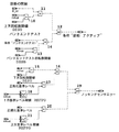
図1に、ノッキングセンサの診断の際のプロシージャを示す本発明の実施例が図示されている。ノッキングセンサの診断のために、正規化された基準レベル、すなわち用いられる増幅器段を考慮した基準レベルが、上方および下方の適用可能な検知閾値と比較される。正規化された基準レベルが上方の閾値を上回るか又は正規化された基準レベルが下方の閾値を下回る場合に、エラーが検出される。ノッキング検出装置において正規化された基準レベルを形成する際の詳細なプロシージャが、例えば国際出願番号PCT/DE94/01041の明細書に記載されており公知である。したがってここでは詳述しない。
【0013】
センサリード線への電磁波の入射により、回転数の低い場合ひいてはノイズの小さい場合には、下方の検知閾値に対するノイズ間隔(S/N比)は非常に小さい。確実なエラー検出を保証するために、診断は適用可能な回転数閾値以上になってはじめて開始される。この比較的に高い回転数閾値により、公知の解決策では、エラーが比較的に遅くなってはじめて検出できる。
【0014】
図1にブロック線図として示した実施例において、例えば内燃機関の制御装置のなかで経過する診断が、次のように行われる。診断を開始するために、ブロック10にて、エンジンの回転数すなわち内燃機関の回転数nmotが上方の回転数閾値DZSOよりも大きいかどうか検査される。エンジン回転数が上方の回転数閾値より大きく、且つ、ノッキング制御(Klopfregelung)がアクティブである場合、AND回路11の出力側に相応する信号が送出される。この信号はブロック12(OR回路)に供給され、入力の少なくとも1つが1であるならば、前記ブロック12の出力側に条件”診断 アクティブ”が生ずる。
【0015】
診断の開始に加えて、さらにバンドエンドテストが行われる。このバンドエンドテストでは、ブロック13にて、エンジンの回転数nmotが第2の回転数閾値DZSBよりも大きいかどうか検査される。この比較により、回転数nmotがバンドエンドテスト回転数閾値DZSBよりも大きいことが判明すると、ANDブロック14に相応する情報が供給される。条件”バンドエンドテスト”が満たされており、且つ、エンジン回転数がバンドエンドテスト回転数閾値DZSBよりも大きいことが検出される場合には、条件”診断 アクティブ”がブロック12を介して送出され、ノッキングセンサ診断が実施される。
【0016】
条件”診断 アクティブ”が生じている場合には、ブロック15にて、エンジン回転数が下方の回転数閾値DZSUを上回っているかどうか検査される。エンジン回転数が下方の回転数閾値DZSUを上回っていれば、ANDブロック16に相応する情報が供給される。さらにブロック17にて、正規化された基準レベルREFPNが下方の基準レベル閾値REFPUよりも小さいかどうか検査される。前記下方の基準レベル閾値REFPUはブロック18にて回転数に依存して形成される。基準レベル閾値の形成の際に例えば、基準レベルの計算に関連して国際出願番号PCT/DE94/01041明細書において記載されているような方法が行われる。
【0017】
ブロック17において質問により、正規化された基準レベルREFPNが下方の閾値REFPUよりも大きいことがわかると、相応する信号がブロック16に送出される。ブロック16にてAND演算が行われる。AND演算は、ブロック15の質問条件が満たされている場合、すなわち、エンジン回転数が下方の回転数閾値よりも大きく、且つ正規化された基準レベルREFPNが下方の閾値REFPUよりも小さい場合にのみ、イエスの出力信号(ハイ信号(high))を送出する。
【0018】
ブロック16の出力側がアクティブである場合、ブロック19の出力側に、ノッキングセンサエラーが生じているとの情報が送出される。さらにブロック20において、正規化された基準レベルREFPNがブロック21で形成される上方の閾値REFPOよりも大きいことが検出される場合、ノッキングセンサエラーが検出される。前記上方の閾値REFPOはこの場合、ブロック21にて同様に回転数に依存して形成される。
【0019】
上方および下方の検知閾値に対する2つの別個の回転数閾値DZSOおよびDZSUが評価される、図1に示したプロシージャにより、上方の検知閾値DZSOの診断は、低い回転数の場合でもすでに実施可能である。このことにより、ノッキングセンサの故障は早期に検出可能であり、ひいてはエンジンの損傷が防止できる。なぜなら、図1に示したエラー検出あるいは診断が行われる制御装置は、適時に点火角のシフトを行うことができるからである。
【0020】
バンドエンドテストの範囲内で自動ノッキングセンサ検出を実現するために、この場合、負荷閾値は十分に上げられる。バンドエンドテストのために、固有の回転数閾値がある。この回転数閾値DZSBは、ノッキングセンサの確実な検出を実現するために、標準の回転数閾値を上回っていなければならない。
【0021】
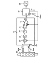
図2に、既述の評価方法が行われるノッキング検出装置が示されている。ノッキング検出装置は既に国際出願PCT/DE94/01041明細書から公知である。
【0022】
そのようなノッキング検出装置では、略線的に示した内燃機関22に2つのノッキングセンサ23a及び23bが配属されており、これらのノッキングセンサは内燃機関の所定の位置に設けられている。ノッキングセンサ23a及び23bは信号S1及びS2を評価回路24に供給し、評価回路24は入力側E1を介してマイクロプロセッサ或いは計算機25に接続されている。計算機は、詳しく図示していない内燃機関の制御装置の構成部分である。計算機25には、別の入力側E2を介して付加的な信号、例えば回転数信号nmotが供給される。計算機25は供給された信号に依存して、例えば内燃機関の点火出力段26及び/又は噴射弁等のような別の装置を、例えば適当な信号を出力側Aにて送出することにより制御する。評価回路全体を、内燃機関の制御装置の計算機25のなかに完全に一体化することもできる。
【0023】
評価回路24は例えば、調整可能な増幅率を有する少なくとも1つの増幅器27を含んでおり、該増幅器にマルチプレクサ28を介して交互に、ノッキングセンサ23a及び23bから供給される出力信号S1及びS2が供給される。後続の帯域フィルタ29および復調回路30例えば検波器において、信号がさらに処理され、最終的に積分器31において積分される。積分された信号すなわち調整された積分値はKIで示されている。KIの値は比較器32において基準レベルREFと比較され、値KIが基準レベルREFを所定の値だけ上回る場合、比較結果によりノッキングが検出される。
【0024】
信号KIおよびREFが供給される比較器32又は図2に示されていない別の比較手段は、エラー検出或いは診断のためにも用いられる。この場合、図1に示した方法が実施される。
【0025】
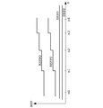
図3には、横軸に回転数nmotをとって、上方および下方の基準レベル閾値REFPO及びREFPUの経過の一例ならびに最小基準レベルが示されている。この最小基準レベルを2つの異なる基準レベルDZSO及びDZSUに分割することにより、本発明の利点が得られる。
【0026】
【発明の効果】
本発明により、ノッキングセンサのエラー又は所定のセンサの機能欠陥が早期に検出され、ひいてはエンジンの損傷が防止できる。
【図面の簡単な説明】
【図1】本発明の診断方法に用いる評価のプロシージャを示す実施例である。
【図2】図1の本発明の診断方法を実施することのできる、国際出願番号PCT/DE94/01041明細書から公知のノッキング検出装置を示す。
【図3】種々の基準レベルの経過を回転数に関連して示した線図である。
【符号の説明】
10〜21 ブロック
DZSO 上方の回転数閾値
DZSB バンドエンドテスト回転数閾値
DZSU 下方の回転数閾値
REFPU 下方の基準レベル閾値
REFPO 上方の基準レベル閾値
22 内燃機関
23a,23b ノッキングセンサ
24 評価回路
25 計算機
26 点火出力段
27 増幅器
28 マルチプレクサ
29 帯域フィルタ
30 復調回路
31 積分器
32 比較器[0001]
BACKGROUND OF THE INVENTION
In the present invention, the evaluation device forms a reference level from the output signal, and the reference level is compared with the upper limit value and / or the lower limit value for error detection, and the actual reference level is only the value given in advance. The present invention relates to a diagnostic method in a sensor, for example a knocking sensor of an internal combustion engine, which is determined to be an error if it exceeds an upper limit value and / or falls below a lower limit value and is only diagnosed if a minimum detection threshold is exceeded.
[0002]
[Prior art]
It is well known that a reliable diagnosis must be made in a sensor, for example a knocking sensor used for knocking detection and therefore for knocking control of an internal combustion engine. This diagnosis ensures on the one hand that it reliably detects a functional defect of the sensor and, on the other hand, reliably prevents false detection of detection errors, for example knocking.
[0003]
For example, each knocking sensor is assigned to one cylinder of the internal combustion engine, and the knocking sensor transmits an output signal. This output signal detects whether knocking has occurred in the cylinder, that is, whether combustion with knocking has occurred, by means of signal processing and a special evaluation method. In the case of knocking, undesired combustion is to be avoided.
[0004]
Knocking detection methods including diagnosis are known, for example, from International Application No. PCT DE 94/01041. In this known method, as is generally done by the knocking detection method, the number of revolutions is obtained from the output signal of one knocking sensor or a plurality of knocking sensors, for example, solid-propagating sound sensors, by the control device of the internal combustion engine. A dependent normalized reference level is formed. Depending on the reference level, a reference level threshold value depending on the rotational speed is formed, and at this time, an upper and lower reference level threshold value are obtained, respectively. Both reference level threshold values are stored as characteristic curves (maps) in the electronic memory of the control device of the internal combustion engine. The reference level is formed so that the reference level corresponds to the volume of the internal combustion engine in an operation without knocking. For this purpose, the reference level or the normalized reference level derived therefrom is used, for example, within a predetermined measurement window in the case of the above conditions where no knocking is detected using the integration of the output signal of the knocking sensor. Will be implemented.
[0005]
In known methods for true fault detection, each normalized actual reference level is compared to a reference level threshold that depends on both speeds. A functional defect is detected when a predetermined deviation occurs in the normalized actual reference level. At this time, if, for example, below the lower reference level threshold, a knocking sensor malfunction is detected, since in this case no signal is supplied to the evaluation device. Similarly, a functional defect is detected when the upper reference level is exceeded.
[0006]
In order to maintain a safe distance from a high background noise level caused by the incidence of electromagnetic waves on the knocking sensor lead wire, noise, etc., diagnosis is performed only when a predetermined minimum rotational speed threshold is exceeded in known methods. . This threshold value is selected as follows, that is, the interval between the normalized reference level and the background noise is selected such that a reliable inspection can be performed.
[0007]
[Problems to be solved by the invention]
The object of the present invention is to propose a diagnostic method in a sensor, for example a knocking sensor, which has the advantage that a diagnosis can already be carried out when the rotational speed is clearly lower than in the prior art.
[0008]
[Means for Solving the Problems]
The above problem is solved by selecting two different thresholds as the minimum detection threshold by the diagnosis and error detection method of the present invention.
[0009]
In this case, a reference level is formed in the evaluation device from the output signal of the sensor, the reference level is compared with the upper limit value and / or the lower limit value for error detection, and the actual reference level is given in advance. Only if the upper limit value is exceeded and / or below the lower limit value, an error is determined. However, a diagnosis is only made if the minimum detection threshold is exceeded, but this minimum detection threshold can take two different values.
[0010]
Further advantages of the invention are realized by the features described in the dependent claims.
[0011]
DETAILED DESCRIPTION OF THE INVENTION
Next, the present invention will be described in detail based on embodiments with reference to the drawings.
[0012]
FIG. 1 illustrates an embodiment of the present invention illustrating a procedure for diagnosing a knocking sensor. For diagnosis of the knocking sensor, the normalized reference level, i.e. the reference level taking into account the amplifier stage used, is compared with the upper and lower applicable detection thresholds. An error is detected if the normalized reference level is above the upper threshold or the normalized reference level is below the lower threshold. A detailed procedure for creating a normalized reference level in a knock detection device is described, for example, in the specification of international application number PCT / DE94 / 01041. Therefore, it is not detailed here.
[0013]
When the rotational speed is low and the noise is small due to the incidence of electromagnetic waves on the sensor lead wire, the noise interval (S / N ratio) with respect to the lower detection threshold is very small. In order to ensure reliable error detection, the diagnosis is started only when it exceeds the applicable speed threshold. Due to this relatively high rotational speed threshold, known solutions can only be detected when the error is relatively slow.
[0014]
In the embodiment shown as a block diagram in FIG. 1, for example, a diagnosis that passes in a control device for an internal combustion engine is performed as follows. To start the diagnosis, it is checked in
[0015]
In addition to the start of diagnosis, a further band end test is performed. In this band end test, it is checked in
[0016]
If the condition “diagnostic active” has occurred, it is checked in
[0017]
If the query in
[0018]
When the output side of
[0019]
With the procedure shown in FIG. 1, in which two separate speed thresholds DZSO and DZSU are evaluated for the upper and lower detection thresholds, the diagnosis of the upper detection threshold DZSO can already be carried out even at low speeds. . Thus, a knocking sensor failure can be detected at an early stage, and as a result, engine damage can be prevented. This is because the control device that performs error detection or diagnosis shown in FIG. 1 can shift the ignition angle in a timely manner.
[0020]
In order to achieve automatic knocking sensor detection within the band end test, the load threshold is raised sufficiently in this case. For band end testing, there is an inherent speed threshold. This rotation speed threshold value DZSB must exceed the standard rotation speed threshold value in order to realize reliable detection of the knocking sensor.
[0021]
FIG. 2 shows a knocking detection apparatus in which the above-described evaluation method is performed. Knocking detection devices are already known from the international application PCT / DE94 / 01041.
[0022]
In such a knocking detection device, two knocking
[0023]
The
[0024]
The
[0025]
FIG. 3 shows an example of the progress of the upper and lower reference level thresholds REFPO and REFPU and the minimum reference level with the rotation speed nmot on the horizontal axis. By dividing this minimum reference level into two different reference levels DZSO and DZSU, the advantages of the present invention are obtained.
[0026]
【The invention's effect】
According to the present invention, an error of a knocking sensor or a functional defect of a predetermined sensor is detected at an early stage, and as a result, engine damage can be prevented.
[Brief description of the drawings]
FIG. 1 is an example showing an evaluation procedure used in the diagnostic method of the present invention.
2 shows a knock detection device known from International Application No. PCT / DE94 / 01041, in which the diagnostic method of the invention of FIG. 1 can be implemented.
FIG. 3 is a diagram showing the course of various reference levels in relation to the rotational speed.
[Explanation of symbols]
10 to 21 block DZSO Upper rotational speed threshold DZSB Band end test rotational speed threshold DZSU Lower rotational speed threshold REFPU Lower reference level threshold REFPO Upper
Claims (1)
前記評価装置は前記出力信号から基準レベルを形成し、該基準レベルはエラー検出のために上方の限界値及び下方の限界値と比較され、実基準レベルが前もって与えられた値だけ前記上方の限界値を上回る又は下方の限界値を下回る場合にエラーと決定される、診断方法において、
2つの異なる回転数の閾値が設けられており、
上方の回転数の閾値を上回る場合に診断が行われ、
下方の回転数の閾値のみを上回る場合には、基準レベルに対し上方の限界値に関して診断が行われ、下方の限界値に関する診断はまだ抑制される、
ことを特徴とする診断方法。A diagnostic method for evaluating an output signal of a knocking sensor of an internal combustion engine using an evaluation device,
The evaluator forms a reference level from the output signal, the reference level is compared with an upper limit value and a lower limit value for error detection, and the actual reference level is set to the upper limit by a predetermined value. In a diagnostic method, where an error is determined if a value is exceeded or below a lower limit value,
Two different rotation speed thresholds are provided,
Diagnosis is made when the upper rotation speed threshold is exceeded,
If only the lower rotational speed threshold is exceeded, a diagnosis is made for the upper limit value relative to the reference level, and the diagnosis for the lower limit value is still suppressed,
A diagnostic method characterized by the above.
Applications Claiming Priority (2)
| Application Number | Priority Date | Filing Date | Title |
|---|---|---|---|
| DE10043501A DE10043501A1 (en) | 2000-09-01 | 2000-09-01 | Method of monitoring detonation in motor vehicle internal combustion engine involves comparing detected values to reference value |
| DE10043501.7 | 2000-09-01 |
Publications (3)
| Publication Number | Publication Date |
|---|---|
| JP2002115599A JP2002115599A (en) | 2002-04-19 |
| JP2002115599A5 JP2002115599A5 (en) | 2008-07-24 |
| JP4460802B2 true JP4460802B2 (en) | 2010-05-12 |
Family
ID=7654902
Family Applications (1)
| Application Number | Title | Priority Date | Filing Date |
|---|---|---|---|
| JP2001266397A Expired - Fee Related JP4460802B2 (en) | 2000-09-01 | 2001-09-03 | Diagnostic method in a sensor, for example a knocking sensor |
Country Status (5)
| Country | Link |
|---|---|
| US (1) | US6588252B2 (en) |
| JP (1) | JP4460802B2 (en) |
| DE (2) | DE10043501A1 (en) |
| FR (1) | FR2813639B1 (en) |
| IT (1) | ITMI20011819A1 (en) |
Families Citing this family (6)
| Publication number | Priority date | Publication date | Assignee | Title |
|---|---|---|---|---|
| JP4355254B2 (en) * | 2004-05-14 | 2009-10-28 | 三菱電機株式会社 | Knocking detection device for internal combustion engine |
| US20130199809A1 (en) * | 2010-03-31 | 2013-08-08 | Alfing Montagetechnik Gmbh | Assembly device and assembly method |
| DE102010040271A1 (en) * | 2010-09-06 | 2012-03-08 | Robert Bosch Gmbh | Method and device for setting an emergency operation in a faulty system for detecting pre-ignition in an internal combustion engine |
| EP2743482B1 (en) * | 2012-12-11 | 2021-01-27 | Caterpillar Motoren GmbH & Co. KG | Knock control system, combustion engine and method of operating the same |
| DE102014102324A1 (en) * | 2014-02-24 | 2015-08-27 | Dr. Ing. H.C. F. Porsche Aktiengesellschaft | Method for detecting a knocking combustion of an internal combustion engine |
| FR3091584A1 (en) * | 2019-01-08 | 2020-07-10 | Psa Automobiles Sa | METHOD OF FUNCTIONAL DIAGNOSIS OF A CLUTCH OF AIR CONDITIONING COMPRESSOR BY A VIBRATION SENSOR |
Family Cites Families (8)
| Publication number | Priority date | Publication date | Assignee | Title |
|---|---|---|---|---|
| DE2836445C2 (en) * | 1978-08-19 | 1979-11-15 | Te Ka De Felten & Guilleaume Fernmeldeanlagen Gmbh, 8500 Nuernberg | Circuit arrangement for error detection in digital signals |
| DE4117807A1 (en) * | 1991-05-31 | 1992-12-03 | Bosch Gmbh Robert | KNOCK DETECTION METHOD |
| DE4332711A1 (en) * | 1993-09-25 | 1995-03-30 | Bosch Gmbh Robert | Device for fault detection in a device for knock detection |
| DE9401041U1 (en) | 1994-01-22 | 1995-06-01 | Puky Fahrzeugfab Gmbh | Children's vehicle with safety pennants |
| DE19756081A1 (en) * | 1997-12-17 | 1999-06-24 | Bosch Gmbh Robert | Monitoring and fault detection procedures |
| WO2000001944A2 (en) * | 1998-07-02 | 2000-01-13 | Siemens Aktiengesellschaft | Method for monitoring the function of detectors in an internal combustion engine and electronic control device working in accordance with said method |
| DE10017543A1 (en) * | 2000-04-08 | 2001-10-11 | Bosch Gmbh Robert | Procedures for error detection and error healing |
| DE10021913A1 (en) * | 2000-05-05 | 2001-11-08 | Bosch Gmbh Robert | Error detection during evaluation of knock sensor signals in internal combustion engine involves forming at least one of the upper and lower thresholds based on preceding reference evaluation |
-
2000
- 2000-09-01 DE DE10043501A patent/DE10043501A1/en not_active Withdrawn
-
2001
- 2001-08-27 US US09/940,197 patent/US6588252B2/en not_active Expired - Lifetime
- 2001-08-28 IT IT2001MI001819A patent/ITMI20011819A1/en unknown
- 2001-08-30 FR FR0111250A patent/FR2813639B1/en not_active Expired - Fee Related
- 2001-08-31 DE DE10142799A patent/DE10142799B4/en not_active Expired - Fee Related
- 2001-09-03 JP JP2001266397A patent/JP4460802B2/en not_active Expired - Fee Related
Also Published As
| Publication number | Publication date |
|---|---|
| FR2813639A1 (en) | 2002-03-08 |
| DE10043501A1 (en) | 2002-03-14 |
| ITMI20011819A0 (en) | 2001-08-28 |
| FR2813639B1 (en) | 2008-02-15 |
| US20020050270A1 (en) | 2002-05-02 |
| US6588252B2 (en) | 2003-07-08 |
| JP2002115599A (en) | 2002-04-19 |
| DE10142799B4 (en) | 2010-03-11 |
| ITMI20011819A1 (en) | 2003-02-28 |
| DE10142799A1 (en) | 2002-07-25 |
Similar Documents
| Publication | Publication Date | Title |
|---|---|---|
| JP4550358B2 (en) | Method and apparatus for error identification or diagnosis | |
| US6912460B2 (en) | Method for detecting knock in an internal combustion engine | |
| JP2893233B2 (en) | Diagnostic device for in-cylinder pressure sensor | |
| JP3998719B2 (en) | Method for determining a phase position in a four-cycle internal combustion engine | |
| RU2002107440A (en) | Method and device for detecting malfunctions, respectively, diagnostics of knock sensor | |
| US6317681B2 (en) | Method for monitoring the operation of sensors in an internal combustion engine, and electronic controller operating in accordance with the method | |
| JP2005532541A (en) | Driving method for internal combustion engine | |
| JP2001221067A (en) | Gas flow control mechanism in internal combustion engine, in particular, function monitoring method and device for rotary valve | |
| JP3935200B2 (en) | Error detection device for knocking detection device | |
| JP4838479B2 (en) | Method for detecting and correcting errors, and apparatus for detecting and correcting errors | |
| JP4460802B2 (en) | Diagnostic method in a sensor, for example a knocking sensor | |
| US11434844B2 (en) | Method for checking a variable valve lift control of an internal combustion engine | |
| JPH0633837A (en) | Exhaust-gas recirculating diagnostic system of internal combustion engine | |
| JP2582969B2 (en) | Knocking control device for internal combustion engine | |
| JP2002115599A5 (en) | ||
| JP3461627B2 (en) | Device for detecting combustion state of internal combustion engine | |
| JP3131892B2 (en) | Self-diagnosis device in knocking detection device of internal combustion engine | |
| JP2000517393A (en) | Combustion misfire detection method | |
| KR100245698B1 (en) | Method for diagnosing malfunction of a measuring sensor of the amount of air | |
| KR100471222B1 (en) | Cam sensor diagnosis method of vehicle | |
| JP2544511Y2 (en) | Knock detection device for internal combustion engine | |
| JPH03246351A (en) | Misfiring detector for internal combustion engine | |
| JPH0666195A (en) | Knocking detecting device for internal combustion engine | |
| JPH08319878A (en) | Method and device for failure judgement of knock sensor | |
| JPH11326136A (en) | Diagnosing device for exhaust gas circulating device |
Legal Events
| Date | Code | Title | Description |
|---|---|---|---|
| A521 | Request for written amendment filed |
Free format text: JAPANESE INTERMEDIATE CODE: A523 Effective date: 20080606 |
|
| A621 | Written request for application examination |
Free format text: JAPANESE INTERMEDIATE CODE: A621 Effective date: 20080606 |
|
| A131 | Notification of reasons for refusal |
Free format text: JAPANESE INTERMEDIATE CODE: A131 Effective date: 20091002 |
|
| A521 | Request for written amendment filed |
Free format text: JAPANESE INTERMEDIATE CODE: A523 Effective date: 20091216 |
|
| TRDD | Decision of grant or rejection written | ||
| A01 | Written decision to grant a patent or to grant a registration (utility model) |
Free format text: JAPANESE INTERMEDIATE CODE: A01 Effective date: 20100115 |
|
| A01 | Written decision to grant a patent or to grant a registration (utility model) |
Free format text: JAPANESE INTERMEDIATE CODE: A01 |
|
| A61 | First payment of annual fees (during grant procedure) |
Free format text: JAPANESE INTERMEDIATE CODE: A61 Effective date: 20100215 |
|
| R150 | Certificate of patent or registration of utility model |
Free format text: JAPANESE INTERMEDIATE CODE: R150 |
|
| FPAY | Renewal fee payment (event date is renewal date of database) |
Free format text: PAYMENT UNTIL: 20130219 Year of fee payment: 3 |
|
| FPAY | Renewal fee payment (event date is renewal date of database) |
Free format text: PAYMENT UNTIL: 20140219 Year of fee payment: 4 |
|
| R250 | Receipt of annual fees |
Free format text: JAPANESE INTERMEDIATE CODE: R250 |
|
| R250 | Receipt of annual fees |
Free format text: JAPANESE INTERMEDIATE CODE: R250 |
|
| R250 | Receipt of annual fees |
Free format text: JAPANESE INTERMEDIATE CODE: R250 |
|
| LAPS | Cancellation because of no payment of annual fees |