JP4460740B2 - Door safety device - Google Patents
Door safety device Download PDFInfo
- Publication number
- JP4460740B2 JP4460740B2 JP2000260141A JP2000260141A JP4460740B2 JP 4460740 B2 JP4460740 B2 JP 4460740B2 JP 2000260141 A JP2000260141 A JP 2000260141A JP 2000260141 A JP2000260141 A JP 2000260141A JP 4460740 B2 JP4460740 B2 JP 4460740B2
- Authority
- JP
- Japan
- Prior art keywords
- door
- weight member
- weight
- displaced
- slide
- Prior art date
- Legal status (The legal status is an assumption and is not a legal conclusion. Google has not performed a legal analysis and makes no representation as to the accuracy of the status listed.)
- Expired - Fee Related
Links
Images


Landscapes
- Wing Frames And Configurations (AREA)
Description
【0001】
【発明の属する技術分野】
本発明は、扉と戸当たり枠との間に挟まれて扉の全閉を妨げる突出位置を保持し得る状態と、戸当たり枠に突き当たると扉の全閉を妨げないように没入位置へ移動し得る状態とが選択されるストッパ部材を備える扉用安全装置に関するものである。
【0002】
【従来の技術】
日常生活の中で、勢いよく扉を閉めることがある。このような加速度を扉に与える閉め方を不用意に行うと、ともすれば扉と戸当たり枠との間に指を挟んだりする事故を起こすおそれがある。このような事故を誘発させないために、不用意に引き戸を閉めても縦框と戸当たり枠との間に隙間が開くように、引き戸の縦框と戸当たり枠との間に出没自在なストッパを設けるようにした技術が特開平8−4409号公報に開示されている。
【0003】
【発明が解決しようとする課題】
しかるに、この先行技術によると、引き戸を開ける際に縦框と戸当たり枠との間に自動的にストッパが突出するので、閉める時には必ずストッパが突き当たることになる。従って、これによると、引き戸を全閉するには、その都度ストッパを解除位置へ戻さねばならない。これは安全性の面では確実である反面、意識して引き戸を閉める習慣のある者にとっては煩わしさを感じさせることが懸念される。
【0004】
本発明は、このような従来技術の問題点を解消するべく案出されたものであり、その主な目的は、不用意に閉めた時の保安性を損なわずに、意識的に閉める時には煩わしさを感じさせることが無いように扉用安全装置を改良することにある。
【0005】
【課題を解決するための手段】
このような目的を果たすために、本発明の請求項1においては、所定値以上の加速度(例えば0.2G)が作用したときには扉(2,3)の全閉を妨げるようにした扉用安全装置であって、戸当たり枠に対向する扉の部分に、扉の開閉方向に摺動可能に設けられたスライド部材(12)と、前記戸当たり枠に対向する扉の面から所定の長さ突出可能に前記スライド部材に突設されたストッパ部材(13)と、前記扉と前記ストッパ部材との間に設けられ、前記ストッパ部材が突出する向きに前記スライド部材を付勢する第1のばね部材(14)と、前記スライド部材に扉の開閉方向に摺動可能に設けられたウェート部材(15)と、前記スライド部材と前記ウェート部材との間に設けられ、前記ウェート部材を扉の閉方向に付勢する第2のばね部材(16)と、前記ウェート部材が前記第2のばね部材の付勢力に抗して前記スライド部材に対して扉の開方向に所定の位置まで変位した後、前記スライド部材が前記第1のばね部材の付勢力に抗して前記扉に対して扉の開方向に所定の位置まで変位した場合に、前記ウェート部材に係合し、前記ウェート部材を介して、前記ストッパ部材の扉内への没入を妨げるように、前記スライド部材の前記扉に対する摺動を制動すべく前記扉側に設けられた制限手段(19)と、前記ウェート部材が前記スライド部材に対して扉の開方向に所定の位置まで変位した場合に、前記ウェート部材の前記スライド部材に対する相対位置を保持するように前記ウェート部材と係合すべく、前記スライド部材側に設けられたロック手段(18)とを有することを特徴とするものとした。
【0006】
このようにすれば、扉を勢いよく閉め、扉の閉方向への所定値以上の加速度が扉に作用したときに、スライド部材の扉に対する摺動が制動され、ストッパ部材が突出した状態に維持される。これにより、扉と戸当り枠との間に指を詰めることが防止される。すなわち、扉用安全装置は、指詰め安全装置として作動する。一方、ゆっくりと扉を閉める分には何の抵抗も生ぜずに済む。また、扉を閉める過程において一度でも所定値以上の加速度が扉に作用すると、ウェート部材はスライド部材に対して扉の開方向に所定の位置まで変位し、ロック手段によってその位置に保持されるため、スライド部材の扉に対する摺動が制動される。そのため、その後、扉に所定値以上の加速度が加わらないように、ゆっくりと扉を閉めても指詰め安全装置が作動する。
【0007】
本発明の請求項2では、上記構成に加え、前記スライド部材が前記扉に対して扉の開方向に変位した状態から前記第1のばね部材の付勢力によって扉の閉方向へと変位する際に、前記ロック手段に係合し、前記ロック手段と前記ウェート部材との係合を解除する向きに前記ロック手段を変位させる解除手段(26)が前記扉に設けられていることを特徴とするものとした。
【0008】
本発明の請求項3では、上記構成に加え、前記ウェート部材は、前記制限手段側に斜面(20)を有し、前記制限手段は、前記扉を支持する鴨居に形成されたガイド溝(22)と対向する前記扉の部分に摺動可能かつ前記扉の前記ガイド溝と対向する面から突出可能に設けられ、前記ウェート部材側に前記ウェート部材の斜面と係合する斜面(21)を有し、前記ウェート部材が前記第2のばね部材の付勢力に抗して前記スライド部材に対して扉の開方向に所定の位置まで変位した後、前記スライド部材が前記第1のばね部材の付勢力に抗して前記扉に対して扉の開方向に所定の位置まで変位した場合に、前記制限手段の前記斜面に押圧されて前記ガイド溝側へと変位され、前記ガイド溝に圧接されることを特徴とするものとした。これにより、指詰め安全装置が作動すると同時に扉にも制動力が加わる。
【0009】
本発明の請求項4では、前記ウェート部材と前記制限手段との間に低摩擦部材(ガイドプレート17)が介設されることを特徴とするものとした。これにより、指詰め安全装置の作動と扉制動装置の作動との連携が円滑となる。
【0010】
【発明の実施の形態】
以下に添付の図面を参照して本発明について詳細に説明する。
【0011】
図7は、本発明が適用された住宅用アルミサッシュの一例を示している。このサッシュは、固定枠1の内側に2枚の引き違い式ガラス障子2・3を摺動自在に組み込んでなり、アルミニウム合金材で中空に形成された上框4における戸当たり枠1aとの対向部に本発明の安全装置5が組み込まれている。なお、本発明による安全装置5は、例示したガラス障子に限らず、パネル型引き戸や襖など、全ての形式の引き戸に適用可能である。
【0012】
この安全装置5は、図1〜図6に示すように、上框4と実質的に一体をなすケーシング11と、障子3の開閉方向に沿って移動可能なるようにケーシング11内に組み込まれたスライド部材12と、その先端を戸当たり枠1aとの対向面から出没自在なるようにスライド部材12に一体形成されたストッパ突起13と、ストッパ突起13の突出状態を保持するための第1圧縮コイルばね14と、スライド部材12に対して当該スライド部材12と同じ方向について移動自在なるように組み付けられたウェート部材15と、障子3の端面側位置(前進位置)にウェート部材15を保持するための第2圧縮コイルばね16と、スライド部材12の上部にそれぞれの一端を枢着して各遊端を上下に旋回動可能なるガイドプレート17並びにロックプレート18と、ケーシング11の上壁に上下動可能に設けられたブレーキ部材19とからなっている。
【0013】
以下、作動要領を交えて更に詳しく説明する。なお、障子3の閉方向への移動を前進と、開方向への移動を後退と、それぞれ定義する。
【0014】
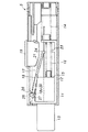
通常、スライド部材12は、第1圧縮コイルばね14の弾発力により、ストッパ突起13を戸当たり枠1aとの対向面から突出させた位置に保持されている。これと同時に、第2圧縮コイルばね16の弾発力により、ウェート部材15も前進位置に保持されている。またガイドプレート17並びにロックプレート19は、その遊端が下向きとなるように傾斜しており、ブレーキ部材19は、その自重により降下している(図1参照)。
【0015】
この状態で、障子3をゆっくりと閉めると、ウェート部材15は、上框4に固定されたケーシング11と相対移動せずに一緒に移動する。そして戸当たり枠1aにストッパ突起13が突き当たってもスライド部材12の後退を妨げるものはないので、ストッパ突起13はケーシング11内に抵抗なく没入し、障子3は完全に閉じられる(図6参照)。なお、第1圧縮コイルばね14の伸長力が常時作用しており、これがスライド部材12の後退を妨げる力とはなるが、障子の重量を押し退けることができない程度にこのばね定数を定めておけば何ら問題とはならない。またこの時、戸当たり枠1aにストッパ突起13が突き当たると、スライド部材12が第1圧縮コイルばね14の伸長力に抗して後退し、スライド部材12が共に後退する。ウェート部材15の上面は後下がりの斜面20とされ、ブレーキ部材19の下面は前上がりの斜面21とされている。そのため、スライド部材12と共に後退する後退するウェート部材15の斜面20によって、ガイドプレート17を介してブレーキ部材19の斜面21が押圧され、ブレーキ部材19がケーシング11の上壁に対して上方に押し上げられる。なお、ウェート部材15がスライド部材12に対して前進位置にあるときは、ウェート部材15に押し上げられたブレーキ部材19の上端が鴨居に設けられた溝22の底部に圧接されないように、斜面20・21の角度が定められている。
【0016】
障子3を勢い良く閉めた時には、慣性の作用によってウェート部材15は障子3の加速度に追従できないので、見かけ上、第2圧縮コイルばね16を押し縮めながらウェート部材15が後退する形となる(図2参照)。このウェート部材15が作動する加速度は、ウェート部材15の重量及び第2圧縮コイルばね16のばね定数で所望に応じて設定可能であり、例えば0.2G以上で作動するように設定すると良い。なお、図2に示されているように、障子3を勢い良く閉めた時にも、スライド部材12は、第1圧縮コイルばね14の弾発力により、ストッパ突起13を戸当り枠1aとの対向面から突出させた位置に保持されている。
【0017】
ウェート部材15の後退限度は、スライド部材12に設けられた突起23と、ガイドプレート17の遊端の鉤形部24とで定められる。またウェート部材15が限度位置まで一旦後退すると、ロックプレート18の遊端が下りてウェート部材15の前上の角に引っ掛かり、加速度が低下してもウェート部材15の前進位置への戻り移動は阻止される。この状態では、ロックプレート18がスライド部材12とウェート部材15との間を突っ張るので、ストッパ突起13が戸当たり枠1aに衝当すると、ウェート部材15の後退位置を保持したままスライド部材12が後退する(図3参照)。
【0018】
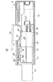
前記の通り、ウェート部材15の上面は後下がりの斜面20とされ、ブレーキ部材19の下面は前上がりの斜面21とされていると共に、ウェート部材15とブレーキ部材19との間に挟まれたガイドプレート17が摩擦係数の低い合成樹脂材で形成されており、スライド部材12と一体的なウェート部材15の後退移動はブレーキ部材19の上昇移動に円滑に変換される。そしてウェート部材15の後退によってガイドプレート17が押し上げられると同時に、ブレーキ部材19が徐々に押し上げられて鴨居側の溝22に圧接される。この楔効果によって障子3に制動力が作用すると共に、スライド部材12は、戸当たり枠1aと障子の上框4の端面4aとの間に指詰め防止寸法Aを残してそれ以上は引っ込めなくなる(図4参照)。
【0019】
他方、ロックプレート18の枢支端18a側には、スライド部材12の上面に引っ掛かる爪25が設けられていると共に、ケーシング11の上壁には、上向きに撓み変形可能な弾発爪26が形成されており、ストッパ突起13が戸当たり枠1aに突き当たってスライド部材12が幾分か後退する行程の間に、ロックプレート18の爪25がこの弾発爪26を押し退けて弾発爪26の後方へと移動する(図4参照)。
【0020】
指詰め防止寸法Aを残して静止した障子3を僅かに開くと、第1圧縮コイルばね14に押されてスライド部材12が前進し、ロックプレート18がこれに引きずられるが、ロックプレート18の枢支端18aの爪25が弾発爪26に引っ掛かるため、ロックプレート18の枢支端18aを受容した障子の移動方向に沿う長溝27が、枢支端18aを置き去りにして前方へ移動する。するとロックプレート18の爪25に対する規制が外れるとともに、爪25が弾発爪26に押圧され、ロックプレート18はその遊端を上向けるように旋回動し、ウェート部材15に作用させていた移動阻止力が解除される。而してウェート部材15が第2圧縮コイルばね16の弾発力で初期位置へと戻される(図5参照)。
【0021】
以上のようにして、スライド部材12が後退可能となり、障子3を閉めるのに支障がなくなる。
【0022】
ウェート部材15がケーシング11内で後退しない程度の速度で障子3を閉めれば、ストッパ突起13の没入を阻止するものがないので、抵抗なく障子3を全閉し得る。
【0023】
いずれにせよ、ウェート部材15が後退位置に保持される加速度を障子3に一度でも与えると、最後はゆっくりと閉めてもストッパ突起13が利くようになってしまう。そしてストッパ突起13が利いてしまっても、開く方向へ障子3を少し動かせば自動的にロックプレート18が解除されるので、障子3を全閉することができる。
【0024】
【発明の効果】
このように本発明によれば、不用意な閉め方をした場合に指を挟むことを防止するためのストッパ機能が引き戸に作用する加速度の程度に応じて自動的に作動するので、安全装置を必要としない使用者に対して閉める度にストッパの解除を強いるという不都合を払拭することができる。また、ストッパ機能が有効となった状態にあっても、引き戸を僅かに開くという簡単な操作でストッパ機能の解除が自動的に行われるので、使用者に煩わしさを感じさせない上、初めからゆっくりと閉めさえすれば抵抗感無く全閉するので、事故を誘発させるような乱雑な閉め方をしないように習慣づけることができる。これに加えて、サッシュ式の引き違い戸は勿論のこと、パネルドアや襖にもビルトインすることができるので高い汎用性が得られる上、扉の上端に組み込むものなので、人の出入りの邪魔にならずに済む。
【図面の簡単な説明】
【図1】本発明の安全装置の通常状態を示す内部構造図
【図2】本発明の安全装置の所定加速度が作用した状態を示す内部構造図
【図3】本発明の安全装置の所定加速度が作用した後に戸当たり枠に衝当した状態を示す内部構造図
【図4】本発明の安全装置の作動状態を示す内部構造図
【図5】本発明の安全装置の作動解除状態を示す内部構造図
【図6】本発明の安全装置の閉扉状態を示す内部構造図
【図7】本発明が適用された住宅用アルミサッシュの一例を示す斜視図
【符号の説明】
1 固定枠
1a 戸当たり枠
2・3 ガラス障子
4 上框
5 安全装置
11 ケーシング
12 スライド部材
13 ストッパ突起
14 第1圧縮コイルばね
15 ウェート部材
16 第2圧縮コイルばね
17 ガイドプレート
18 ロックプレート
18a 枢支端
19 ブレーキ部材
20・21 斜面
22 (鴨居の)溝
23 突起
24 鉤形部
25 爪
26 弾発爪
27 溝[0001]
BACKGROUND OF THE INVENTION
The present invention can hold a projecting position that is sandwiched between the door and the door stop frame and prevents the door from being fully closed, and moves to the immersive position so as not to prevent the door from being fully closed when it hits the door stop frame. It is related with the safety device for doors provided with the stopper member from which the state which can be selected is selected.
[0002]
[Prior art]
In everyday life, the doors can be closed with force. Inadvertently closing the door to give such acceleration may cause an accident in which a finger is caught between the door and the door stop frame. In order not to induce such an accident, even if the sliding door is inadvertently closed, a stopper that can move freely between the vertical fence of the sliding door and the door stopper frame so that a gap is opened between the vertical fence and the door stopper frame. Japanese Patent Application Laid-Open No. H8-4409 discloses a technique for providing the above.
[0003]
[Problems to be solved by the invention]
However, according to this prior art, when the sliding door is opened, the stopper automatically protrudes between the vertical fence and the door stop frame, so that the stopper always comes into contact when the door is closed. Therefore, according to this, in order to fully close the sliding door, the stopper must be returned to the release position each time. While this is certain in terms of safety, there is a concern that it may be annoying for those who are conscious of closing the sliding doors.
[0004]
The present invention has been devised to solve such problems of the prior art, and the main purpose of the present invention is troublesome when consciously closing without losing the security when closed carelessly. The purpose is to improve the safety device for the door so as not to let the user feel it.
[0005]
[Means for Solving the Problems]
In order to achieve such an object, in the first aspect of the present invention, the door safety that prevents the doors (2, 3) from being fully closed when an acceleration (for example, 0.2 G) exceeding a predetermined value is applied . It is a device, and a predetermined length from the surface of the door facing the door-holding frame, and a slide member (12) provided on the door portion facing the door-holding frame so as to be slidable in the door opening / closing direction A stopper member (13) projectingly provided on the slide member and a first spring provided between the door and the stopper member and biasing the slide member in a direction in which the stopper member projects. A member (14), a weight member (15) provided on the slide member so as to be slidable in the opening and closing direction of the door, and provided between the slide member and the weight member; The second case biasing in the direction After the member (16) and the weight member are displaced to a predetermined position in the door opening direction against the slide member against the biasing force of the second spring member, the slide member is moved to the first position. When the spring member is displaced to a predetermined position in the door opening direction against the biasing force of the spring member, it engages with the weight member, and enters the door of the stopper member through the weight member. Limiting means (19) provided on the door side to brake the sliding of the slide member with respect to the door so as to prevent the immersion of the slide member, and the weight member in a predetermined direction in the door opening direction with respect to the slide member when displaced to the position, so as to the weights member and engageable to retain the relative position with respect to the slide member of the weights member, this having a locking means provided on the slide member side (18) It was assumed to be characterized.
[0006]
In this way , the door is closed vigorously , and when an acceleration of a predetermined value or more in the closing direction of the door acts on the door, the sliding of the slide member with respect to the door is braked and the stopper member is maintained in a protruding state. Is done. Thereby, it is prevented that a finger is packed between the door and the door stop frame. That is, the door safety device operates as a finger pad safety device. On the other hand, there is no resistance to slowly closing the door. In addition, when acceleration exceeding a predetermined value is applied to the door even once in the process of closing the door, the weight member is displaced to a predetermined position in the door opening direction with respect to the slide member, and is held at that position by the locking means. The sliding of the sliding member with respect to the door is braked. Therefore, after that, even if the door is slowly closed, the finger padding safety device is operated so that acceleration exceeding a predetermined value is not applied to the door.
[0007]
According to a second aspect of the present invention, in addition to the above configuration, when the slide member is displaced in the door closing direction by the biasing force of the first spring member from a state in which the slide member is displaced in the door opening direction with respect to the door. Further, the door is provided with a release means (26) that engages with the lock means and displaces the lock means in a direction to release the engagement between the lock means and the weight member. It was supposed to be .
[0008]
According to a third aspect of the present invention, in addition to the above configuration, the weight member has a slope (20) on the restricting means side, and the restricting means is a guide groove (22 formed in a duck supporting the door). ) Is slidable on the portion of the door facing the door and protrudes from the surface facing the guide groove of the door, and has an inclined surface (21) that engages the inclined surface of the weight member on the weight member side. Then, after the weight member is displaced to a predetermined position in the door opening direction against the slide member against the biasing force of the second spring member, the slide member is attached to the first spring member. When it is displaced to a predetermined position in the door opening direction against the force, it is pressed by the inclined surface of the restricting means and displaced toward the guide groove, and is pressed against the guide groove. It was characterized by that. As a result, the braking force is applied to the door at the same time that the finger padding safety device operates.
[0009]
According to a fourth aspect of the present invention, a low friction member (guide plate 17) is interposed between the weight member and the restricting means . Thereby, cooperation with the operation | movement of a finger pad safety device and the operation | movement of a door braking device becomes smooth.
[0010]
DETAILED DESCRIPTION OF THE INVENTION
Hereinafter, the present invention will be described in detail with reference to the accompanying drawings.
[0011]
FIG. 7 shows an example of a residential aluminum sash to which the present invention is applied. This sash has two sliding-
[0012]
As shown in FIGS. 1 to 6, the
[0013]
Hereinafter, it will be described in more detail with the operating procedure. The movement of the
[0014]
Normally, the
[0015]
In this state, when the
[0016]
When the
[0017]
The retreat limit of the
[0018]
As described above, the upper surface of the
[0019]
On the other hand, a
[0020]
When the
[0021]
As described above, the
[0022]
If the
[0023]
In any case, if the acceleration at which the
[0024]
【The invention's effect】
As described above, according to the present invention, the stopper function for preventing the fingers from being pinched when inadvertently closing is automatically operated according to the degree of acceleration acting on the sliding door. It is possible to eliminate the inconvenience of forcing the user to cancel the stopper every time the user does not need to close it. Even when the stopper function is enabled, the stopper function is automatically released by a simple operation of opening the sliding door slightly, so that the user does not feel bothersome and slowly from the beginning. As long as it is closed, it will be fully closed without a sense of resistance, so you can make it a habit not to make a messy way to trigger an accident. In addition to this, it can be built in not only to sash type sliding doors, but also to panel doors and coffins, so it is highly versatile and it is built into the top edge of the door, so it does not disturb people. You do n’t have to.
[Brief description of the drawings]
FIG. 1 is an internal structural diagram showing a normal state of the safety device of the present invention. FIG. 2 is an internal structural diagram showing a state in which a predetermined acceleration of the safety device of the present invention is applied. FIG. 4 is an internal structural view showing the operating state of the safety device of the present invention. FIG. 5 is an internal view showing the operating release state of the safety device of the present invention. Structural diagram [Fig. 6] Internal structural diagram showing the closed state of the safety device of the present invention [Fig. 7] Perspective view showing an example of a residential aluminum sash to which the present invention is applied [Explanation of symbols]
DESCRIPTION OF
Claims (4)
戸当たり枠に対向する扉の部分に、扉の開閉方向に摺動可能に設けられたスライド部材と、
前記戸当たり枠に対向する扉の面から所定の長さ突出可能に前記スライド部材に突設されたストッパ部材と、
前記扉と前記ストッパ部材との間に設けられ、前記ストッパ部材が突出する向きに前記スライド部材を付勢する第1のばね部材と、
前記スライド部材に扉の開閉方向に摺動可能に設けられたウェート部材と、
前記スライド部材と前記ウェート部材との間に設けられ、前記ウェート部材を扉の閉方向に付勢する第2のばね部材と、
前記ウェート部材が前記第2のばね部材の付勢力に抗して前記スライド部材に対して扉の開方向に所定の位置まで変位した後、前記スライド部材が前記第1のばね部材の付勢力に抗して前記扉に対して扉の開方向に所定の位置まで変位した場合に、前記ウェート部材に係合し、前記ウェート部材を介して、前記ストッパ部材の扉内への没入を妨げるように、前記スライド部材の前記扉に対する摺動を制動すべく前記扉側に設けられた制限手段と、
前記ウェート部材が前記スライド部材に対して扉の開方向に所定の位置まで変位した場合に、前記ウェート部材の前記スライド部材に対する相対位置を保持するように前記ウェート部材と係合すべく、前記スライド部材側に設けられたロック手段と
を有することを特徴とする扉用安全装置。 A door safety device that prevents the door from being fully closed when an acceleration greater than a predetermined value is applied,
A sliding member provided on a portion of the door facing the door stop frame so as to be slidable in the opening and closing direction of the door;
A stopper member projecting on the slide member so as to protrude a predetermined length from the surface of the door facing the door stop frame;
A first spring member provided between the door and the stopper member and biasing the slide member in a direction in which the stopper member protrudes;
A weight member provided on the slide member so as to be slidable in a door opening and closing direction;
A second spring member provided between the slide member and the weight member and biasing the weight member in a door closing direction;
After the weight member is displaced to a predetermined position in the door opening direction with respect to the slide member against the biasing force of the second spring member, the slide member acts on the biasing force of the first spring member. When it is displaced against the door to a predetermined position in the door opening direction, it engages with the weight member and prevents the stopper member from entering the door through the weight member. Limiting means provided on the door side to brake the sliding of the sliding member relative to the door;
When the weight member is displaced to a predetermined position in the opening direction of the door with respect to the slide member, the slide is engaged with the weight member so as to maintain a relative position of the weight member with respect to the slide member. Locking means provided on the member side;
Door safety device and having a.
前記制限手段は、前記扉を支持する鴨居に形成されたガイド溝と対向する前記扉の部分に摺動可能かつ前記扉の前記ガイド溝と対向する面から突出可能に設けられ、前記ウェート部材側に前記ウェート部材の斜面と係合する斜面を有し、前記ウェート部材が前記第2のばね部材の付勢力に抗して前記スライド部材に対して扉の開方向に所定の位置まで変位した後、前記スライド部材が前記第1のばね部材の付勢力に抗して前記扉に対して扉の開方向に所定の位置まで変位した場合に、前記制限手段の前記斜面に押圧されて前記ガイド溝側へと変位され、前記ガイド溝に圧接されることを特徴とする、請求項1または請求項2に記載の扉用安全装置。 The weight member has a slope on the limiting means side,
The restricting means is provided so as to be slidable on a portion of the door facing the guide groove formed in the duck supporting the door and projecting from the surface facing the guide groove of the door, and on the weight member side The weight member has a slope that engages with the slope of the weight member, and the weight member is displaced to a predetermined position in the opening direction of the door with respect to the slide member against the biasing force of the second spring member. When the slide member is displaced to a predetermined position in the door opening direction against the door against the biasing force of the first spring member, the guide groove is pressed against the inclined surface of the limiting means. The door safety device according to claim 1 or 2, wherein the door safety device is displaced to the side and is pressed against the guide groove .
Priority Applications (1)
| Application Number | Priority Date | Filing Date | Title |
|---|---|---|---|
| JP2000260141A JP4460740B2 (en) | 2000-08-30 | 2000-08-30 | Door safety device |
Applications Claiming Priority (1)
| Application Number | Priority Date | Filing Date | Title |
|---|---|---|---|
| JP2000260141A JP4460740B2 (en) | 2000-08-30 | 2000-08-30 | Door safety device |
Publications (2)
| Publication Number | Publication Date |
|---|---|
| JP2002070411A JP2002070411A (en) | 2002-03-08 |
| JP4460740B2 true JP4460740B2 (en) | 2010-05-12 |
Family
ID=18748195
Family Applications (1)
| Application Number | Title | Priority Date | Filing Date |
|---|---|---|---|
| JP2000260141A Expired - Fee Related JP4460740B2 (en) | 2000-08-30 | 2000-08-30 | Door safety device |
Country Status (1)
| Country | Link |
|---|---|
| JP (1) | JP4460740B2 (en) |
Cited By (1)
| Publication number | Priority date | Publication date | Assignee | Title |
|---|---|---|---|---|
| KR101504509B1 (en) | 2014-11-14 | 2015-03-20 | 주식회사 우정유빅스엔지니어링종합감리전문회사 | A structure of softening the impact for a door closing |
Families Citing this family (1)
| Publication number | Priority date | Publication date | Assignee | Title |
|---|---|---|---|---|
| DE202008015721U1 (en) * | 2008-11-27 | 2010-05-27 | MACO Vermögensverwaltung GmbH | Fitting arrangement and sliding element |
-
2000
- 2000-08-30 JP JP2000260141A patent/JP4460740B2/en not_active Expired - Fee Related
Cited By (1)
| Publication number | Priority date | Publication date | Assignee | Title |
|---|---|---|---|---|
| KR101504509B1 (en) | 2014-11-14 | 2015-03-20 | 주식회사 우정유빅스엔지니어링종합감리전문회사 | A structure of softening the impact for a door closing |
Also Published As
| Publication number | Publication date |
|---|---|
| JP2002070411A (en) | 2002-03-08 |
Similar Documents
| Publication | Publication Date | Title |
|---|---|---|
| US8186010B2 (en) | Retracting mechanism and fixing structure | |
| JP5474797B2 (en) | Door safety mechanism | |
| JP4912998B2 (en) | Sliding door automatic closing device | |
| JP5982420B2 (en) | Sliding door braking device | |
| JP4847209B2 (en) | Hinged door shock absorber | |
| JP4460740B2 (en) | Door safety device | |
| US5447347A (en) | Auxiliary door stop | |
| JP5660695B2 (en) | Airtight sliding door device | |
| WO2020050789A2 (en) | Locking mechanism with additional damping mechanism | |
| GB2262565A (en) | Stay having releasable catch | |
| JP5990007B2 (en) | Finger pinching prevention device | |
| JP3925887B2 (en) | Drawer closing device | |
| JPH09165969A (en) | Door with finder-protection device | |
| CA2946913A1 (en) | Door closing mechanism having hands-free hold-open feature | |
| JP2580077Y2 (en) | Locking device for dead bolt in lock | |
| KR101876388B1 (en) | Apparatus for preventing fingers from inserting between door and doorframe for sliding door | |
| JPH0520845Y2 (en) | ||
| KR102382839B1 (en) | Stopper device on the door with hand protection | |
| JPH084445A (en) | Airtightness holding device for door | |
| JP2010270454A (en) | Sliding door apparatus | |
| JP7377140B2 (en) | fittings | |
| JP3242091B2 (en) | Lid opening and closing device | |
| JP2945612B2 (en) | Anti-shock lock | |
| JP3041307B2 (en) | Storage box with wing, auto lock device and dead bolt used for the storage box | |
| JP6193338B2 (en) | Sliding door optional opening position stop device |
Legal Events
| Date | Code | Title | Description |
|---|---|---|---|
| A621 | Written request for application examination |
Free format text: JAPANESE INTERMEDIATE CODE: A621 Effective date: 20070223 |
|
| A977 | Report on retrieval |
Free format text: JAPANESE INTERMEDIATE CODE: A971007 Effective date: 20080131 |
|
| A131 | Notification of reasons for refusal |
Free format text: JAPANESE INTERMEDIATE CODE: A131 Effective date: 20090804 |
|
| RD13 | Notification of appointment of power of sub attorney |
Free format text: JAPANESE INTERMEDIATE CODE: A7433 Effective date: 20090826 |
|
| A521 | Written amendment |
Free format text: JAPANESE INTERMEDIATE CODE: A523 Effective date: 20090909 |
|
| A521 | Written amendment |
Free format text: JAPANESE INTERMEDIATE CODE: A821 Effective date: 20090826 |
|
| TRDD | Decision of grant or rejection written | ||
| A01 | Written decision to grant a patent or to grant a registration (utility model) |
Free format text: JAPANESE INTERMEDIATE CODE: A01 Effective date: 20100126 |
|
| A01 | Written decision to grant a patent or to grant a registration (utility model) |
Free format text: JAPANESE INTERMEDIATE CODE: A01 |
|
| A61 | First payment of annual fees (during grant procedure) |
Free format text: JAPANESE INTERMEDIATE CODE: A61 Effective date: 20100215 |
|
| R150 | Certificate of patent (=grant) or registration of utility model |
Free format text: JAPANESE INTERMEDIATE CODE: R150 |
|
| FPAY | Renewal fee payment (prs date is renewal date of database) |
Free format text: PAYMENT UNTIL: 20130219 Year of fee payment: 3 |
|
| FPAY | Renewal fee payment (prs date is renewal date of database) |
Free format text: PAYMENT UNTIL: 20130219 Year of fee payment: 3 |
|
| FPAY | Renewal fee payment (prs date is renewal date of database) |
Free format text: PAYMENT UNTIL: 20130219 Year of fee payment: 3 |
|
| FPAY | Renewal fee payment (prs date is renewal date of database) |
Free format text: PAYMENT UNTIL: 20130219 Year of fee payment: 3 |
|
| LAPS | Cancellation because of no payment of annual fees |