JP4457593B2 - Finger authentication device - Google Patents
Finger authentication device Download PDFInfo
- Publication number
- JP4457593B2 JP4457593B2 JP2003207010A JP2003207010A JP4457593B2 JP 4457593 B2 JP4457593 B2 JP 4457593B2 JP 2003207010 A JP2003207010 A JP 2003207010A JP 2003207010 A JP2003207010 A JP 2003207010A JP 4457593 B2 JP4457593 B2 JP 4457593B2
- Authority
- JP
- Japan
- Prior art keywords
- finger
- blood vessel
- authentication
- unit
- vessel pattern
- Prior art date
- Legal status (The legal status is an assumption and is not a legal conclusion. Google has not performed a legal analysis and makes no representation as to the accuracy of the status listed.)
- Expired - Fee Related
Links
Images


Landscapes
- Measurement Of The Respiration, Hearing Ability, Form, And Blood Characteristics Of Living Organisms (AREA)
- Image Input (AREA)
Description
【0001】
【発明の属する技術分野】
本発明は生体情報を用い個人を識別する認証装置に関し、特に指の血管パターンに基づく指認証装置に関する。
【0002】
【従来の技術】
財産や情報の安全な管理を目的として、個人認証技術への期待が高まっている。特に、人間の体の一部を鍵として利用する生体認証技術は、従来の暗証番号や鍵による管理に比べ、遺失や盗難等による不正行使の恐れが少ないことから注目を集めている。生体認証技術としては、指紋をはじめ、顔や虹彩、手や指の血管パターンなどを用いた様々な手法が研究されている。中でも、指の血管パターンを用いた認証方法は、指紋のように犯罪を連想させたり、虹彩のように直接眼球に光を照射したりすることがないので心理的抵抗感が少なく、また、生体の表面ではなく内部の特徴を読み取るため、偽造が困難という利点がある。
具体的には、次のようにして、指の血管パターンによる認証が実現されている。まず近赤外光を発する光源を用意し、その光を撮影するように対峙させてカメラを設置する。カメラには、近赤外域の波長だけを通すような光学フィルタを装着する。認証時には、カメラと光源の間に指を挿入し、そのときの指の画像を撮る。血液中の成分は近赤外光を良く吸収するため、血管部分は光が透過せずに暗く映る。このようにして撮影された血管パターンの画像と、登録されている血管パターンの画像との間で照合を行い、個人認証を行う。
【0003】
【発明が解決しようとする課題】
血管パターンの一致を正しく検出するためには、登録時と認証時とで、同じ撮影条件で画像を取得できなくてはならない。例えば、指が回転すれば、得られる血管パターンも大きく異なる。撮影される指の面が変化しない移動や回転については簡単な画像処理によって補正できるが、指の面が背腹逆転するような回転については、未知の部分が存在するために画像処理による補正はできない。この点について、例えば、手の甲の血管パターンを用いた認証装置として、4本の指でガイドバーを握りしめることを必須とすることで、撮像される手の甲の位置が個人毎に一定になるよう矯正する試みがされている。しかし、指の血管の場合、握るなどの緊張を加えると、前述のように血管が圧迫されて血管パターンが欠落する可能性がある。また、何らかのガイドレールを設け、その特定の位置に指を合わせて置く方法も考えられるが、正しい置き方を学習する必要があり、誰でもが簡単に使えるとはいえない。
また、認証装置に挿入したときの指の姿勢によっても、得られる血管パターンは変化する。例えば、力を入れて過度に伸ばした状態にある指は、表皮の緊張によって血管が圧迫されて血管パターンが部分的に欠落する場合がある。さらに、認証装置全体を照らしている外光が変化するだけでも、得られる画像の明るさやコントラストが変わって、認証精度に影響を与える。通常の太陽光や照明光の中にも、近赤外域の光が含まれており、光が回り込んで血管パターンに影響を与えるからである。
本発明の目的は、従来の技術では同一性が保証できなかった、認証ごとの撮影条件を、ユーザにとって負担のない操作体系の中で低コストに均一化させることにある。
【0004】
【課題を解決するための手段】
上記の目的を達成するため、本発明の指認証装置においては、指の位置を決めるためのガイド部と、前記指の先端部分によってオンオフされるスイッチ部と、指が配置される場所を挟むように設けて指を透過する透過光を照射する光源と、撮像部と、スイッチ部オンになることにより、撮像部で撮影された画像の認証動作を行う認証部とを有する指認証装置を提供する。
また、指を屈曲した姿勢で位置決めさせるためのガイド部と、指が配置される場所を挟むように設け指を透過する透過光を照射する光源と、撮像部と、撮像部で撮影された画像の認証動作を行う認証部とを有する指認証装置を提供する。
これにより、指の位置を自然に特定の位置に誘導することが可能となり、さらに血管を圧迫することないため、撮影した画像に対して、安定した照合をおこなうことができ、結果として、認証の精度を著しく向上させることができる。
【0005】
【発明の実施の形態】
以下、本発明の1実施例を詳細に説明する。
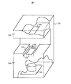
図1は、本発明を実現する認証装置100の概略図である。本体は、大きく分けて光源部102と撮像部104の2つに分けられる。光源部と撮像部の間には空間が設けられ、認証時には、その空間に指を挿入する。光源部は、指が挿入される空間の上部を屋根のようにして覆い、天井等からの照明が直接撮像部に侵入しないよう遮光の役割を果たす。ここでは空間の側壁が存在しない例を示しているが、側壁を設けて、横側からの外光の侵入も阻止するようにしてもよい。この場合、認証精度を向上させるため、側壁に近赤外線の乱反射を防止するための反射防止剤等の塗料を塗布するか、反射防止材料で側壁を構成することが望ましい。光源部には、波長810ナノメートル前後の近赤外光を発する光源106が、撮像部のカメラ114側に向けて光を放つように設置されている。光源とカメラとの間に指を挿入することで、指を近赤外光が透過し、それをカメラで撮影することによって指の血管パターン画像が得られる。ガイド溝112は、指の正しい挿入位置や向きを直感的に理解しやすい形で提示する。ガイド溝に合わせて指を置くと、指先にあたる部分にボタンスイッチ108があり、指の第1、第2関節前後の部分に開口部110が位置する。開口部110は、透明なガラスやアクリル板で覆われ、光は通しつつ、認証装置内部に異物が入り込むのを防止する。カメラ114には、近赤外波長域の光のみを透過する光学フィルタが必要なため、上記ガラスやアクリル板の替わりに、光学フィルタの板を用いることで、二つの機能を一つの板にまとめることもできる。
【0006】
認証は、ユーザがボタンスイッチ108を押すことで始まる。ボタンを押すという操作自体は、多くの人々が日常生活で頻繁に行っている行為であり、認証にかかる一連の操作体系の中においても、ごく自然に溶け込ませることができる。ボタンを押そうと、ごく自然に指を置いたときの指先の位置は、人によってほぼ一定しているか、少なくとも無理なく再現できる。指先の位置が決まれば、ガイド溝112に誘導されて、指全体としての置く向きも必然的に決まるため、開口部110の上に位置する指の部位がほぼ一意に決まり、撮影される指画像の範囲も同様に決まる。また、ボタンを押す動作をする際には、関節の曲がる方向が決まっているため、指の腹が、ボタンの凹む方向に対して鉛直面となるように自然に向く。そのため、指の背側を撮ったり、腹側を撮ったりといったような、指の胴回りの回転によって撮影される指の面が変わってしまうこともない。
また、ボタンを押すときには、指は自然に曲がった状態になり、指先以外には不必要に表皮に緊張を与えることがないので、血管の圧迫によるパターンの欠落も起こりにくい。また、自然に曲がった状態であれば、開口部110のガラス面に指が触れることもなく、ガラス面との接触によって血管が圧迫されたり、汚れが付着したり、といったこともない。
【0007】
さらに、これらによって、指の位置がほぼ一定にできれば、開口部の面積を、指で覆い尽くせるほどに小さくして外光の入射を避けることで、外光による明るさやコントラストの変化も防ぐことができる。従来は、指位置が一定にできないため、開口部を大きめにとって広範囲に撮像した指の画像の中から、登録時と同じパターンを持つ部分を探索する必要があった。そのため、パターンの探索に高コストな演算ハードウェアを必要とし、開口部が大きいために、外光が入りやすく、ノイズに弱いという問題があったが、ボタンの設置によって、それが解消される。
【0008】
そしてまた、従来の指血管パターンによる認証技術では、スイッチ等によるユーザ主導の認証開始要求手段が用意されていなかったため、認証の処理がいつ始まるのかは認証装置主導で決められ、ユーザに混乱を与える危険性もあった。このように、ボタンスイッチの設置は、それだけで操作性を高める手段として非常に有効である。なお、ガイド溝112については、図示した形状に限定されない。また、ガイド溝に指が必ずしも接触する必要もない。例えば、針金状のガイドや単に指置き形状のガイドであっても良く、要は、指を一義的に導くことが可能であれば良い。
【0009】
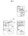
図11には、図1の発明の別形態である3面図を示す。図1とは、指を挿入する箇所の構成が異なっている。図11に示したように、開口部を備える空間下部は、指を挿入する手前側と奥側とで、空間の上部の高さ方向の距離がことなっている。また、空間の上部にあたる光源106と、空間の下部に当たる開口部110の面は、弧を描くように形成されている。ここで空間上部の弧と、空間下部の弧とでは、前者の弧の方が曲率を大きくとってある。この構成により、指を挿入するときに、例えば、指の腹が横若しくは斜めを向く方向であった場合にも、空間の奥に行くほど狭くさらに弧が形成されているため、指を挿入していくに従って、自然と指の腹が下を向くように矯正される。さらに、光源106からの近赤外が均等に照射されるとともに、カメラ114から開口部110までの距離が均等になり、より精度の高い認証をおこなうことが可能となる。
【0010】
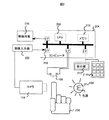
図2は、本発明を実現するシステム構成の概略ブロック図の一例である。200は手であり、光源106とカメラ114との間に、その指を挿入して、スイッチ108の押下に合わせて血管パターンの画像信号を取得する。カメラ114の画像信号は、画像入力器202によってデジタルデータに変換され、コンピュータ204の入出力インタフェース206を介してメモリ210に格納される。スイッチ108も同様に入出力インタフェースを介して接続され、オン・オフの状態がメモリ210に格納されるか、もしくは、オンになると同時にCPU208に対して割り込み信号を発生する。CPU208は、スイッチ108の状態がオンになったのを確認するか、もしくはオンになった割り込み信号を検知すると、認証を行うソフトウェアプログラムを起動し実行する。そして、プログラムの処理結果に基づき、結果を表示器212に表示したり、制御対象216に適切な信号を送って扉を開閉したり、といった各種制御を行う。キーボード214は、例えば、暗証番号などの、認証に関する補助情報を入力するなどに用いる。
【0011】
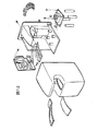
図12には、図11及び図2に示した指認証装置の組み立て斜視図を示す。
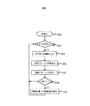
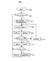
図3は、上記ハードウェア、特にCPU208によって実行されるソフトウェアフローの一例を示している。処理300では、ハードウェア全体の初期化やプログラム実行に必要となる一時変数に初期値を代入する。初期状態への移行が完了すると、プログラムはアイドリング状態に入り、スイッチ108がオンになるのを待つ(302)。スイッチがオンになったら、カメラ114で撮影した指の画像をメモリ210に取り込む(304)。取り込んだ画像データについて画像処理を行い、血管パターンの特徴を抽出し(306)、すでに登録してあるパターンと一致するものがないか照合探索を行う(308)。もし、一致するパターンが存在すれば(310)、認証を必要としている機器やソフトウェアプログラム等の制御対象に対して、正当なアクセス権が認証された旨の信号、もしくは認証された個人の識別用データを送信する(312)。そして、次にスイッチがオンになるまで再び待機する。尚、本ハードウェアの電源の入切を、ボタンスイッチ108と兼用することも可能である。ボタンスイッチ108によって電源が入り、上記ソフトウェアフローを、処理302を除いて処理310まで、認証成功時ならば312まで順次実行した後、再び電源を遮断する。これによって待機時の消費電力を低減することができる。同様に、光源のオンオフのみを制御するような形態も考えられる。ボタンスイッチ108のオンと同時に光源をオンにし、認証処理終了と同時にオフにする。システム全体の電源のオンオフは、構成によっては起動に時間がかかる場合もあるので、利便性を重視する場合には光源部分の省電力化のみにとどめる。光源のオンオフは、スイッチ108に物理的に連動させても良いし、コンピュータ204の入出力インタフェース206に、リレーやトランジスタ等によるスイッチ回路を接続して光源のスイッチを電子制御するようにしてもよい。このような電子制御回路を用いる方法では、スイッチのオンオフを高速に切り替えることによる電力制御方法、いわゆるPWM(Pulse Width Modulation)制御に回路を転用することができ、光源の明るさを段階的に制御することが可能になる。人によって指の太さは異なるため、画一的な光量では血管パターンがうまく現れる人も現れない人も発生するが、最も良好に血管パターンが現れるまで光量を制御しながら連続的に撮像することで、認証の精度を高めることができる。さらに指の太さを計測するセンサーを追加すれば、指の太さと最適光量との関係を予め計算して記憶しておくことで、より少ない枚数の撮像で最適な血管パターンが得られる。
【0012】
図9に、指の太さに応じて光量制御を行う処理のフローチャートを示す。処理900では、ハードウェア全体の初期化やプログラム実行に必要となる一時変数に初期値を代入する。初期状態への移行が完了すると、プログラムはアイドリング状態に入り、スイッチ108がオンになるのを待つ(ステップ902)。スイッチがオンになったら、まず指の太さをセンサー等で測定し、その太さと初期光量値との組を予め登録しておいた参照テーブルを用いて、光源106の初期光量を設定する。続いてカメラ114で指の画像を撮影し、メモリ210に取り込む(ステップ906)。取り込んだ画像データについて、血管パターンの特徴抽出処理908を行って血管パターンが現れているか検査し(ステップ912)、なければ光量を変化させ(ステップ910)、再度カメラから画像を取り込む。光量を変化させる方向は、指の部分の画像領域が全体に明るい場合には、光量が強く飽和気味の傾向が予測されるので光量を下げる方向に、逆に全体に暗い場合には、光量が弱いために透過光のS/N比が下がっている傾向が予測されるので光量を上げる方向に操作する。指領域の全体の明るさは、その構成画素の平均値から容易に計測できる。そして、すでに登録してあるパターンと一致するものがないか照合探索を行い(ステップ914)、一致するパターンが存在すれば(ステップ916)、認証を必要としている機器やソフトウェアプログラム等の制御対象に対して、正当なアクセス権が認証された旨の信号、もしくは認証された個人の識別用データを送信する(ステップ918)。そして、次にスイッチがオンになるまで再び待機する。
【0013】
図10は、指の太さを計測する際に、センサーを用いずに行う方法の一例である。図10−Aは、光源において、それに対峙したカメラが映し出す面を示している。中央の106が光源であり、周りを近赤外線の反射を抑える、もしくは吸収する塗料を塗布した面1000が囲んでいる。その面に、今度は逆に近赤外線を反射しやすい素材の棒状のマーキング1002を施している。光源が光ると、1000と1002の間には、明確なコントラストが生ずる。カメラで撮影すると、両者の間の輝度差は非常に大きくなる。図10―Bのように、指200を光源にかざすと、指の太さに応じて、マーキングの隠される面積が変化する。指部分の画像領域内では、血管とそうでない部分との輝度差は極端には大きくなることがないので、指がマーキング部分を覆うと、マーキング部分に存在した輝度差がなくなる。すなわち、輝度差の大きい部分が、どこで途絶えたかの位置座標が指の外郭位置を与え、これは非常に簡単な差分処理で求められる。指の太さを求める分には、最低2点のマーキングがあればよいのだが、指は太さは節などがあって一様ではないので、図のように4点のマーキングを使うと、より正確な太さを決定できる。また4点使えば、指が若干傾いて挿入された場合でも、その傾き角度を求めることができる。
【0014】
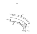
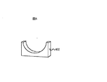
図4は、認証装置の一実施例において、指を挿入する部分を側面から見た拡大図である。上部に近赤外光源106があり、下部に光学開口部110があって、その下にカメラ114がある。400はボタンスイッチのタッチ部分であり、指が直接触れて押されることで、接点スイッチ108がオンになる。108はバネ付きプッシュスイッチであり、押されている間だけ導電状態になり、放されるとバネで自動的に初期位置に戻り、絶縁状態になる。図のように、開口部110からボタン400までの間は、指が自然に屈曲するように弧を描くようにデザインすると、確実に指が曲がるので、すでに述べた血管の圧迫によるパターンの欠落がさらに起こりにくくなる。また、開口部110を形成するガラス板をより下方に設置するか、もしくは指置き台402を設けることで、指の付け根が開口部110に対して浮き上がるようにし、これによって開口部110と指が接触することによる血管圧迫をより確実に防ぐことができる。
【0015】
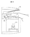
図13には、指を挿入する部分を側面から見た拡大図の別な実施例を示す。図4と比較すると、ボタンスイッチ1301の位置が異なる。図13のボタンスイッチ1301においては、図4のボタンスイッチ400とは異なり、指を奥に押し込むような動作により、接点スイッチ108の操作が行われる。この場合、図4のボタンスイッチ400よりも、ボタンスイッチ1301の押下は不自然な動作となるが、例えば、ボタンスイッチ1301をタッチセンサ等のクリック動作を伴わないスイッチ手段にすることにより、快適な操作感を得ることができる。図5は、ボタン400をさらに拡大して示した図である。指の触れる面には、指がちょうどフィットするように、凹み等の造形を施し、指先の位置が、より確実に毎回同位置に来るようにし、また、ボタンを押すこと自体による位置ずれを起こさないようにできる。また、図4でも示しているように、ボタンの高さは、ちょうど指先の腹部分が収まるだけに制限し、上部に空間を設けることで、爪を長く伸ばしていたり、付け爪をしていたりする人でも不自由なくボタンを押すことができる。図6は、指の付け根部分に設けた指置き台402の拡大図である。単なる板状の突起でも構わないが、図のように、指の太さよりもやや大きめ程度の半円形に加工することで、指を置いたときの横方向のずれを自然に防ぐことができる。この場合、指置き台402は、独立した手段というよりは、前述のガイド溝112の1バリエーションとなっており、どこに指を置けばよいのかガイドの役目も果たしている。
【0016】
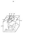
図7は、認証装置100の、別のバリエーションの1例である。図1の例では、天井照明などからの遮光のため、屋根のような形で光源部102を設けたが、ユーザにとっては、逆に、遮蔽された空間に指を挿入するという心理的不安感を煽る場合がある。そこで、図7ように、光源を指の斜め上方に配置することで、指をユーザの視界から完全に隠してしまうような覆いをなくすことができる。図の例では、開口部の両側に斜めの屋根型光源部を設け、光源106をそれぞれ配置している。光源を両側2箇所に設けるのは、1箇所だと指の透過光に偏りが生じて斑になり、正しい血管パターンが得られなくなる可能性もあるからである。
【0017】
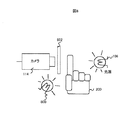
図8は、認証装置100の、また別の光学系配置の一例である。光源800は、透過光源106に対して反射光源を提供する。これら2つの光源は、コンピュータ204からの制御によって任意の組み合わせでオンオフ可能とする。例えば、反射光源800に可視光を発生させ、指の表面をカメラ114で撮像するようにしてもよい。上記実施例では、光学フィルタは近赤外域のみを透過するとしてきたが、ここではその替わりに、可変もしくは切り替え型の光学フィルタ802を設けることで、必要に応じて可視光も通すように切り替え可能とする。これによって、指表面の指紋パターン等の生体特徴を撮像することが可能になり、指表面の生体特徴と血管パターンによる認証を同時に行うことで、認証精度を高めることが可能になる。
【0018】
以上では、認証装置におけるボタンスイッチの利用がもたらす利点について述べたが、ボタンを押すという動作は、装置との接触を意味し、衛生面での抵抗感をもたらす可能性もないわけではない。これについては、装置筐体やボタンに最近では一般的に用いられている抗菌素材を用いることで、それを緩和することができる。特に、筐体に「抗菌」の文字を印刷できるだけでも心理的効果は大きい。本発明の装置構成では、血管パターンを取得するためのセンサー部は、筐体表面に現れている必要はなく、装置表面の抗菌加工は非常に容易である。指紋をはじめ、センサーが直接生体に触れる必要がある生体認証方法では、センサーの抗菌化に難を抱える場合が多いが、本発明では問題がない。
【0019】
また、上記実施例では、ボタンスイッチに機械式のプッシュスイッチを例にしたが、触れるだけで導電する、例えば静電タイプのスイッチを400と108の替わりに用いても構わない。あるいは光源と光センサーの組を用いて、所定の位置に指先が来て、光が遮られたらスイッチが入るような形式にしても構わない。この場合、同様に人感センサー等の各種センサーも利用できる。
【0020】
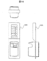
図14には、テンキー部を備えた指認証装置を示している。このテンキー部1401により、万が一、指による認証に失敗した場合においても、予め登録しておいた暗証番号等により、認証をおこなうことが可能となる。また、指による認証と暗証番号による認証とを組み合わせることにより、より確実な認証を可能とする。さらに、指による認証をおこなった場合と、暗証番号による認証とを行った場合とにより、認証後の動作を変える等の応用が可能となる。
【0021】
【発明の効果】
本発明によれば、指の位置が特定の位置に自然に誘導され、撮影画像に対して、位置合わせや回転補正を行う必要なしに安定した照合を行うことができ、また、指の圧迫等による血管パターンの欠落がないので、認証の精度を向上させることができる。
【図面の簡単な説明】
【図1】本発明を実現する装置形態の一例。
【図2】本発明を実現する装置システム構成の一例。
【図3】本発明を実現するソフトウェアフローの一例。
【図4】装置における指挿入部分の断面図の一例。
【図5】ボタンスイッチの形状の一例。
【図6】指置き台の形状の一例。
【図7】本発明を実現する装置形態の別の例。
【図8】本発明を実現する光学系構成の一例。
【図9】本発明の光量制御をおこなうソフトウェアフローの一例。
【図10】本発明の指の太さを測定する構成の一例。
【図11】本発明を実現する指認証装置の3面図。
【図12】本発明を実現する指認証装置の組み立て斜視図。
【図13】装置における指挿入部分の断面図の第2の実施例。
【図14】テンキー部を備えた指認証装置の一例。
【符号の説明】
100…認証装置筐体、102…認証装置光源部、104…認証装置撮像部、106…近赤外光源、108…ボタンスイッチ、110…光学開口部、112…ガイド溝、114…カメラ、200…手、202…画像入力器、204…コンピュータ、206…入出力インタフェース、208…中央演算装置、210…メモリ、212…表示器、214…キーボード、216…制御対象。[0001]
BACKGROUND OF THE INVENTION
The present invention relates to an authentication device for identifying an individual using biometric information, and more particularly to a finger authentication device based on a blood vessel pattern of a finger.
[0002]
[Prior art]
Expectations for personal authentication technology are increasing for the purpose of safe management of property and information. In particular, biometric authentication technology that uses a part of the human body as a key has attracted attention because it is less likely to be illegally exercised due to loss or theft, compared to the conventional management using a personal identification number or key. As biometric authentication technology, various methods using a fingerprint, a face and an iris, a blood vessel pattern of a hand and a finger, and the like have been studied. Among them, the authentication method using the blood vessel pattern of the finger has little psychological resistance because it does not associate a crime like a fingerprint or irradiates light directly on the eye like an iris. Since the internal features are read instead of the surface, there is an advantage that counterfeiting is difficult.
Specifically, authentication by a blood vessel pattern of a finger is realized as follows. First, a light source that emits near-infrared light is prepared, and a camera is set up so that the light is photographed. The camera is equipped with an optical filter that passes only wavelengths in the near infrared region. At the time of authentication, a finger is inserted between the camera and the light source, and an image of the finger at that time is taken. Since components in blood absorb near-infrared light well, the blood vessel part appears dark without transmitting light. Collation is performed between the image of the blood vessel pattern photographed in this way and the image of the registered blood vessel pattern to perform personal authentication.
[0003]
[Problems to be solved by the invention]
In order to correctly detect the matching of the blood vessel pattern, it is necessary to acquire an image under the same imaging conditions at the time of registration and at the time of authentication. For example, if the finger rotates, the blood vessel pattern obtained varies greatly. Movement and rotation that does not change the surface of the finger to be photographed can be corrected by simple image processing, but rotation that causes the finger surface to reverse the back and back is unknown, so correction by image processing is not possible. Can not. In this regard, for example, as an authentication device using a blood vessel pattern on the back of the hand, it is essential to hold the guide bar with four fingers, so that the position of the back of the hand to be imaged is corrected for each individual. An attempt has been made. However, in the case of a finger blood vessel, if a tension such as grasping is applied, the blood vessel is compressed as described above, and the blood vessel pattern may be lost. In addition, it is possible to provide a guide rail and place the finger at a specific position. However, it is necessary to learn how to place it correctly, and it cannot be used easily by anyone.
The obtained blood vessel pattern also changes depending on the posture of the finger when inserted into the authentication apparatus. For example, in a finger that is excessively stretched with force, a blood vessel pattern may be partially lost due to the blood vessel being compressed by the tension of the epidermis. Furthermore, even if the external light that illuminates the entire authentication apparatus changes, the brightness and contrast of the obtained image change, which affects the authentication accuracy. This is because normal sunlight or illumination light also includes near-infrared light, and the light wraps around and affects the blood vessel pattern.
An object of the present invention is to uniformize photographing conditions for each authentication, which cannot be guaranteed by the conventional technology, at a low cost in an operation system that does not burden the user.
[0004]
[Means for Solving the Problems]
In order to achieve the above object, in the finger authentication device of the present invention, a guide part for determining the position of the finger, a switch part that is turned on / off by the tip part of the finger, and a place where the finger is placed are sandwiched. Provided is a finger authentication device that includes a light source that irradiates transmitted light that passes through a finger, an imaging unit, and an authentication unit that performs an authentication operation of an image captured by the imaging unit when the switch unit is turned on. .
In addition, a guide unit for positioning the finger in a bent posture, a light source that radiates transmitted light that is provided so as to sandwich the place where the finger is placed, an imaging unit, and an image captured by the imaging unit There is provided a finger authentication device having an authentication unit for performing the authentication operation.
As a result, the finger position can be naturally guided to a specific position, and the blood vessel is not compressed, so that the captured image can be stably collated, and as a result, authentication can be performed. The accuracy can be remarkably improved.
[0005]
DETAILED DESCRIPTION OF THE INVENTION
Hereinafter, an embodiment of the present invention will be described in detail.
FIG. 1 is a schematic diagram of an
[0006]
Authentication starts when the user presses the
Further, when the button is pressed, the finger is naturally bent, and the epidermis is not unnecessarily tensioned except for the fingertip. Therefore, a pattern is not easily lost due to blood vessel compression. Further, in a naturally bent state, the finger does not touch the glass surface of the
[0007]
In addition, if the finger position can be made almost constant, the area of the opening can be made small enough to be covered with the finger to avoid the incidence of external light, thereby preventing changes in brightness and contrast due to external light. it can. Conventionally, since the finger position cannot be made constant, it has been necessary to search for a portion having the same pattern as that at the time of registration from the image of a finger captured over a wide range with a large opening. For this reason, there is a problem that high-cost calculation hardware is required for searching for a pattern, and since the opening is large, there is a problem that external light is likely to enter and it is susceptible to noise.
[0008]
In addition, in the conventional finger blood vessel pattern authentication technology, there is no user-initiated authentication start request means using a switch or the like, so when the authentication process starts is determined by the authentication device, which causes confusion to the user There was also danger. Thus, the installation of the button switch is very effective as a means for improving operability by itself. The
[0009]
FIG. 11 shows a three-view drawing which is another embodiment of the invention of FIG. 1 is different from the configuration shown in FIG. As shown in FIG. 11, in the lower part of the space including the opening, the distance in the height direction of the upper part of the space is different between the front side and the back side where the finger is inserted. Further, the
[0010]
FIG. 2 is an example of a schematic block diagram of a system configuration for realizing the present invention.
[0011]
FIG. 12 shows an assembled perspective view of the finger authentication device shown in FIGS. 11 and 2.
FIG. 3 shows an example of the software flow executed by the hardware, particularly the
[0012]
FIG. 9 shows a flowchart of processing for performing light amount control according to the thickness of the finger. In
[0013]
FIG. 10 is an example of a method performed without using a sensor when measuring the thickness of a finger. FIG. 10-A shows the surface of the light source that the camera facing it projects. A
[0014]
FIG. 4 is an enlarged view of a part into which a finger is inserted as seen from the side in one embodiment of the authentication device. There is a near infrared
[0015]
FIG. 13 shows another example of an enlarged view of a part where a finger is inserted as seen from the side. Compared with FIG. 4, the position of the
[0016]
FIG. 7 is an example of another variation of the
[0017]
FIG. 8 is an example of another optical system arrangement of the
[0018]
In the above, the advantage brought about by the use of the button switch in the authentication device has been described. However, the operation of pressing the button means contact with the device, and it is not without the possibility of causing a sense of hygiene resistance. This can be mitigated by using an antibacterial material that has been generally used recently for the device casing and buttons. In particular, the psychological effect is great even if the characters “antibacterial” can be printed on the housing. In the apparatus configuration of the present invention, the sensor unit for acquiring the blood vessel pattern does not need to appear on the surface of the casing, and the antibacterial processing of the apparatus surface is very easy. In a biometric authentication method in which a sensor needs to touch a living body directly such as a fingerprint, there are many cases where it is difficult to make the sensor antibacterial, but there is no problem in the present invention.
[0019]
In the above-described embodiment, a mechanical push switch is used as an example of the button switch. However, for example, an electrostatic type switch that conducts electricity only by touching may be used instead of 400 and 108. Alternatively, a combination of a light source and an optical sensor may be used so that the fingertip comes to a predetermined position and is switched on when the light is blocked. In this case, various sensors such as a human sensor can also be used.
[0020]
FIG. 14 shows a finger authentication device having a numeric keypad. With the
[0021]
【The invention's effect】
According to the present invention, the position of the finger is naturally guided to a specific position, and it is possible to perform stable verification on the captured image without the need for alignment and rotation correction, and finger compression, etc. Therefore, the accuracy of authentication can be improved.
[Brief description of the drawings]
FIG. 1 shows an example of an apparatus configuration for realizing the present invention.
FIG. 2 shows an example of an apparatus system configuration for realizing the present invention.
FIG. 3 shows an example of a software flow for realizing the present invention.
FIG. 4 is an example of a cross-sectional view of a finger insertion portion in the apparatus.
FIG. 5 shows an example of the shape of a button switch.
FIG. 6 shows an example of the shape of a finger rest.
FIG. 7 shows another example of an apparatus configuration for realizing the present invention.
FIG. 8 shows an example of an optical system configuration for realizing the present invention.
FIG. 9 shows an example of a software flow for performing light quantity control according to the present invention.
FIG. 10 shows an example of a configuration for measuring the thickness of a finger according to the present invention.
FIG. 11 is a three-side view of a finger authentication device that implements the present invention.
FIG. 12 is an assembled perspective view of a finger authentication device that implements the present invention.
FIG. 13 shows a second embodiment of a cross-sectional view of a finger insertion part in the apparatus.
FIG. 14 shows an example of a finger authentication device having a numeric keypad.
[Explanation of symbols]
DESCRIPTION OF
Claims (12)
前記設置される指を透過する透過光を照射する光源と、
前記透過光に対して透光性を有する部材からなる光学開口部と、
前記透過光を前記光学開口部を介して撮像する撮像部と、
前記光学開口部を介し前記撮像部で撮影された画像から血管パターンを抽出し、前記抽出した血管パターンと予め登録された登録パターンとの照合を行う認証部とを有し、
前記指の腹側を下方と定義したとき、
前記光学開口部が前記ガイド部と前記指との接触箇所より下方に設置され、
上記ガイド部は、上記設置される指を上記光学開口部より該指の付け根側で支持する指置き台と、該指の先端を支持する先端支持部とを有し、上記先端支持部は上記指置き台より下方に設置され、当該先端支持部は、上記光学開口部に指が接触しないように指先の腹側を保持する第一保持部と、上記設置される指の根元側から指先側方向の移動を制限する第二保持部とを有し、
前記光源は、上記透過光を少なくとも指の甲側方向と指の両側面方向との間である2方向から照射するものであって、該指の上面を開放するように前記設置された指の位置と前記撮像部とを結ぶ直線上から外れて配置されることを特徴とする指認証装置。A finger placement guide for positioning the installed finger;
A light source that irradiates transmitted light that passes through the installed finger;
An optical opening made of a member having translucency with respect to the transmitted light;
An imaging unit for imaging the transmitted light through the optical aperture;
An authentication unit that extracts a blood vessel pattern from an image photographed by the imaging unit through the optical aperture, and compares the extracted blood vessel pattern with a pre-registered registration pattern;
When the ventral side of the finger is defined as below,
The optical opening is installed below the contact point between the guide part and the finger,
The guide portion includes a finger rest that supports the finger to be installed on the base side of the finger from the optical opening, and a tip support portion that supports the tip of the finger. The tip support unit is installed below the finger rest, and the tip support unit includes a first holding unit that holds the ventral side of the fingertip so that the finger does not contact the optical opening, and a fingertip side from the base side of the finger to be installed A second holding part for restricting movement in the direction,
The light source irradiates the transmitted light from at least two directions between the direction of the back of the finger and the direction of both sides of the finger, and the light of the finger placed so as to open the upper surface of the finger A finger authentication device, wherein the finger authentication device is arranged out of a straight line connecting a position and the imaging unit.
前記タッチセンサがオンになることにより、前記認証部は前記照合を行うことを特徴とする請求項1乃至3の何れかに記載の指認証装置。Has a touch sensor,
The finger authentication device according to claim 1, wherein the authentication unit performs the verification when the touch sensor is turned on.
前記スイッチ部が押し込まれたことを契機に、前記前記認証部は照合を行うことを特徴とする請求項1乃至3の何れかに記載の指認証装置。When the finger is placed on the guide portion, the switch portion is pushed by the tip portion of the finger,
The finger authentication device according to any one of claims 1 to 3, wherein the authentication unit performs verification when the switch unit is pushed.
前記指を透過する透過光を照射する光源と、A light source that emits transmitted light that passes through the finger;
前記透過光に対して透光性を有する部材からなる光学開口部と、An optical opening made of a member having translucency with respect to the transmitted light;
前記透過光を前記光学開口部を介して撮像する撮像部と、An imaging unit for imaging the transmitted light through the optical aperture;
前記光学開口部を介し前記撮像部で撮影された画像から血管パターンを抽出する処理部とを有し、A processing unit for extracting a blood vessel pattern from an image photographed by the imaging unit through the optical opening,
前記指の腹側を下方と定義したとき、When the ventral side of the finger is defined as below,
前記光学開口部に撮像時の前記設置された指が触れないように、前記光学開口部が前記ガイド部と前記指との接触箇所より下方に設置され、The optical opening is installed below the contact portion between the guide part and the finger so that the installed finger does not touch the optical opening during imaging,
上記ガイド部は、前記設置される指を前記光学開口部より該指の付け根側で支持する指置き台と該指の先端を支持する先端支持部とを有し、上記先端支持部は上記指置き台より下方に設置され、当該先端支持部は、上記光学開口部に指が接触しないように指先の腹側を保持する第一保持部と、上記設置される指の根元側から指先側方向の移動を制限する第二保持部とを有し、The guide section includes a finger rest that supports the finger to be installed on the base side of the finger with respect to the optical opening, and a tip support section that supports the tip of the finger. The tip support unit is installed below the pedestal, and the tip support unit includes a first holding unit that holds the ventral side of the fingertip so that the finger does not contact the optical opening, and a fingertip side direction from the base side of the installed finger A second holding part that restricts movement of the
前記光源は、上記透過光を少なくとも指の甲側方向と指の両側面方向との間である2方向から照射するものであって、該指の上面を開放するように前記設置された指の位置と前記撮像部とを結ぶ直線上から外れて配置されることを特徴とする上記血管パターンを用いた認証用の指血管パターン抽出装置。The light source irradiates the transmitted light from at least two directions between the direction of the back of the finger and the direction of both sides of the finger, and the light of the finger placed so as to open the upper surface of the finger A finger blood vessel pattern extraction apparatus for authentication using the blood vessel pattern, wherein the finger blood vessel pattern is placed off a straight line connecting a position and the imaging unit.
Priority Applications (1)
| Application Number | Priority Date | Filing Date | Title |
|---|---|---|---|
| JP2003207010A JP4457593B2 (en) | 2003-08-11 | 2003-08-11 | Finger authentication device |
Applications Claiming Priority (1)
| Application Number | Priority Date | Filing Date | Title |
|---|---|---|---|
| JP2003207010A JP4457593B2 (en) | 2003-08-11 | 2003-08-11 | Finger authentication device |
Related Parent Applications (1)
| Application Number | Title | Priority Date | Filing Date |
|---|---|---|---|
| JP2001218949A Division JP3617476B2 (en) | 2001-07-19 | 2001-07-19 | Finger authentication device |
Related Child Applications (4)
| Application Number | Title | Priority Date | Filing Date |
|---|---|---|---|
| JP2008320416A Division JP4945549B2 (en) | 2008-12-17 | 2008-12-17 | Finger authentication device |
| JP2008320415A Division JP4631964B2 (en) | 2008-12-17 | 2008-12-17 | Finger authentication device |
| JP2009207686A Division JP4760969B2 (en) | 2009-09-09 | 2009-09-09 | Finger authentication device |
| JP2009207687A Division JP4697329B2 (en) | 2009-09-09 | 2009-09-09 | Finger authentication device |
Publications (3)
| Publication Number | Publication Date |
|---|---|
| JP2004070943A JP2004070943A (en) | 2004-03-04 |
| JP2004070943A5 JP2004070943A5 (en) | 2005-10-27 |
| JP4457593B2 true JP4457593B2 (en) | 2010-04-28 |
Family
ID=32025721
Family Applications (1)
| Application Number | Title | Priority Date | Filing Date |
|---|---|---|---|
| JP2003207010A Expired - Fee Related JP4457593B2 (en) | 2003-08-11 | 2003-08-11 | Finger authentication device |
Country Status (1)
| Country | Link |
|---|---|
| JP (1) | JP4457593B2 (en) |
Families Citing this family (8)
| Publication number | Priority date | Publication date | Assignee | Title |
|---|---|---|---|---|
| KR100944021B1 (en) * | 2004-11-15 | 2010-02-24 | 닛본 덴끼 가부시끼가이샤 | Biometric Features Input Device |
| JP4851723B2 (en) * | 2005-03-04 | 2012-01-11 | 富士通株式会社 | Internal structure image acquisition device, internal structure image acquisition method, and internal structure image acquisition program |
| JP4527031B2 (en) * | 2005-08-25 | 2010-08-18 | 株式会社日立情報制御ソリューションズ | Personal authentication device |
| JP4676371B2 (en) * | 2006-04-11 | 2011-04-27 | ルネサスエレクトロニクス株式会社 | Solid-state imaging device, imaging method, and imaging system |
| JP4783333B2 (en) * | 2007-06-12 | 2011-09-28 | 株式会社日立情報制御ソリューションズ | Finger vein pattern input device for personal authentication device |
| JP5034713B2 (en) * | 2007-06-28 | 2012-09-26 | 株式会社日立製作所 | Finger vein authentication device and information processing device |
| JP5144461B2 (en) | 2008-10-17 | 2013-02-13 | 株式会社日立製作所 | Finger vein authentication device and personal authentication device |
| JP5624110B2 (en) * | 2012-11-22 | 2014-11-12 | 株式会社 日立産業制御ソリューションズ | Biometric authentication device |
-
2003
- 2003-08-11 JP JP2003207010A patent/JP4457593B2/en not_active Expired - Fee Related
Also Published As
| Publication number | Publication date |
|---|---|
| JP2004070943A (en) | 2004-03-04 |
Similar Documents
| Publication | Publication Date | Title |
|---|---|---|
| JP3617476B2 (en) | Finger authentication device | |
| JP2004265269A (en) | Personal authentication device | |
| JP3630675B2 (en) | Finger authentication device | |
| JP4291107B2 (en) | Finger authentication device and finger placement guide | |
| JP4457593B2 (en) | Finger authentication device | |
| JP4631964B2 (en) | Finger authentication device | |
| JP4760969B2 (en) | Finger authentication device | |
| JP4935923B2 (en) | Authentication device and feature pattern extraction device | |
| JP4945549B2 (en) | Finger authentication device | |
| JP5678931B2 (en) | Finger authentication device | |
| JP4697329B2 (en) | Finger authentication device | |
| JP5099256B2 (en) | Finger authentication device | |
| JP6220824B2 (en) | Blood vessel imaging device and authentication device | |
| JP5561328B2 (en) | Blood vessel imaging device and personal authentication device | |
| JP5935861B2 (en) | Finger authentication device | |
| JP5765450B2 (en) | Finger authentication device | |
| JP2008279275A (en) | Personal authentication device and cash dispenser |
Legal Events
| Date | Code | Title | Description |
|---|---|---|---|
| A521 | Request for written amendment filed |
Free format text: JAPANESE INTERMEDIATE CODE: A523 Effective date: 20050726 |
|
| A621 | Written request for application examination |
Free format text: JAPANESE INTERMEDIATE CODE: A621 Effective date: 20050726 |
|
| RD01 | Notification of change of attorney |
Free format text: JAPANESE INTERMEDIATE CODE: A7421 Effective date: 20060421 |
|
| A131 | Notification of reasons for refusal |
Free format text: JAPANESE INTERMEDIATE CODE: A131 Effective date: 20080715 |
|
| A521 | Request for written amendment filed |
Free format text: JAPANESE INTERMEDIATE CODE: A523 Effective date: 20080910 |
|
| A131 | Notification of reasons for refusal |
Free format text: JAPANESE INTERMEDIATE CODE: A131 Effective date: 20081104 |
|
| A521 | Request for written amendment filed |
Free format text: JAPANESE INTERMEDIATE CODE: A523 Effective date: 20081217 |
|
| A131 | Notification of reasons for refusal |
Free format text: JAPANESE INTERMEDIATE CODE: A131 Effective date: 20090324 |
|
| A521 | Request for written amendment filed |
Free format text: JAPANESE INTERMEDIATE CODE: A523 Effective date: 20090519 |
|
| A02 | Decision of refusal |
Free format text: JAPANESE INTERMEDIATE CODE: A02 Effective date: 20090616 |
|
| A521 | Request for written amendment filed |
Free format text: JAPANESE INTERMEDIATE CODE: A523 Effective date: 20090909 |
|
| A911 | Transfer to examiner for re-examination before appeal (zenchi) |
Free format text: JAPANESE INTERMEDIATE CODE: A911 Effective date: 20090925 |
|
| A131 | Notification of reasons for refusal |
Free format text: JAPANESE INTERMEDIATE CODE: A131 Effective date: 20091104 |
|
| A521 | Request for written amendment filed |
Free format text: JAPANESE INTERMEDIATE CODE: A523 Effective date: 20091210 |
|
| TRDD | Decision of grant or rejection written | ||
| A01 | Written decision to grant a patent or to grant a registration (utility model) |
Free format text: JAPANESE INTERMEDIATE CODE: A01 Effective date: 20100119 |
|
| A01 | Written decision to grant a patent or to grant a registration (utility model) |
Free format text: JAPANESE INTERMEDIATE CODE: A01 |
|
| A61 | First payment of annual fees (during grant procedure) |
Free format text: JAPANESE INTERMEDIATE CODE: A61 Effective date: 20100201 |
|
| R151 | Written notification of patent or utility model registration |
Ref document number: 4457593 Country of ref document: JP Free format text: JAPANESE INTERMEDIATE CODE: R151 |
|
| FPAY | Renewal fee payment (event date is renewal date of database) |
Free format text: PAYMENT UNTIL: 20130219 Year of fee payment: 3 |
|
| FPAY | Renewal fee payment (event date is renewal date of database) |
Free format text: PAYMENT UNTIL: 20130219 Year of fee payment: 3 |
|
| FPAY | Renewal fee payment (event date is renewal date of database) |
Free format text: PAYMENT UNTIL: 20140219 Year of fee payment: 4 |
|
| LAPS | Cancellation because of no payment of annual fees |