JP4457149B2 - Sensor for measuring the position of the operating member - Google Patents
Sensor for measuring the position of the operating member Download PDFInfo
- Publication number
- JP4457149B2 JP4457149B2 JP2007521932A JP2007521932A JP4457149B2 JP 4457149 B2 JP4457149 B2 JP 4457149B2 JP 2007521932 A JP2007521932 A JP 2007521932A JP 2007521932 A JP2007521932 A JP 2007521932A JP 4457149 B2 JP4457149 B2 JP 4457149B2
- Authority
- JP
- Japan
- Prior art keywords
- sensor
- circuit
- current
- position sensor
- sensor device
- Prior art date
- Legal status (The legal status is an assumption and is not a legal conclusion. Google has not performed a legal analysis and makes no representation as to the accuracy of the status listed.)
- Expired - Fee Related
Links
Images


Classifications
-
- G—PHYSICS
- G01—MEASURING; TESTING
- G01D—MEASURING NOT SPECIALLY ADAPTED FOR A SPECIFIC VARIABLE; ARRANGEMENTS FOR MEASURING TWO OR MORE VARIABLES NOT COVERED IN A SINGLE OTHER SUBCLASS; TARIFF METERING APPARATUS; MEASURING OR TESTING NOT OTHERWISE PROVIDED FOR
- G01D5/00—Mechanical means for transferring the output of a sensing member; Means for converting the output of a sensing member to another variable where the form or nature of the sensing member does not constrain the means for converting; Transducers not specially adapted for a specific variable
- G01D5/12—Mechanical means for transferring the output of a sensing member; Means for converting the output of a sensing member to another variable where the form or nature of the sensing member does not constrain the means for converting; Transducers not specially adapted for a specific variable using electric or magnetic means
- G01D5/14—Mechanical means for transferring the output of a sensing member; Means for converting the output of a sensing member to another variable where the form or nature of the sensing member does not constrain the means for converting; Transducers not specially adapted for a specific variable using electric or magnetic means influencing the magnitude of a current or voltage
- G01D5/142—Mechanical means for transferring the output of a sensing member; Means for converting the output of a sensing member to another variable where the form or nature of the sensing member does not constrain the means for converting; Transducers not specially adapted for a specific variable using electric or magnetic means influencing the magnitude of a current or voltage using Hall-effect devices
- G01D5/145—Mechanical means for transferring the output of a sensing member; Means for converting the output of a sensing member to another variable where the form or nature of the sensing member does not constrain the means for converting; Transducers not specially adapted for a specific variable using electric or magnetic means influencing the magnitude of a current or voltage using Hall-effect devices influenced by the relative movement between the Hall device and magnetic fields
-
- F—MECHANICAL ENGINEERING; LIGHTING; HEATING; WEAPONS; BLASTING
- F02—COMBUSTION ENGINES; HOT-GAS OR COMBUSTION-PRODUCT ENGINE PLANTS
- F02D—CONTROLLING COMBUSTION ENGINES
- F02D11/00—Arrangements for, or adaptations to, non-automatic engine control initiation means, e.g. operator initiated
- F02D11/06—Arrangements for, or adaptations to, non-automatic engine control initiation means, e.g. operator initiated characterised by non-mechanical control linkages, e.g. fluid control linkages or by control linkages with power drive or assistance
- F02D11/10—Arrangements for, or adaptations to, non-automatic engine control initiation means, e.g. operator initiated characterised by non-mechanical control linkages, e.g. fluid control linkages or by control linkages with power drive or assistance of the electric type
- F02D11/106—Detection of demand or actuation
Description
本発明は、駆動接続部を介して電気モータによって駆動される、内燃機関の操作部材の位置を測定するためのセンサに関する。この操作部材のハウジング内には少なくとも1つの位置センサが配置されている。この位置センサは駆動接続部での位置を検出する。 The present invention relates to a sensor for measuring the position of an operating member of an internal combustion engine driven by an electric motor via a drive connection. At least one position sensor is arranged in the housing of the operating member. This position sensor detects the position at the drive connection.
この種のセンサには、非常に高い信頼性が要求される。なぜなら、機能エラーまたは故障は、場合によっては危険をも生じさせるからである。これはセンサ自体にも、回路へのその電気的な接続部にも関する。ここでこの回路は、センサに動作電圧を供給するとともに、センサの出力信号を受信し、評価する。 This type of sensor requires very high reliability. This is because a functional error or failure can cause danger in some cases. This concerns both the sensor itself and its electrical connection to the circuit. Here, the circuit supplies an operating voltage to the sensor and receives and evaluates the sensor output signal.
このような場合には、このために使用されるケーブル接続部およびコンタクト箇所がエラーの原因となり得る。これ自体は、安全関連システムにおいて、センサおよび接続エレメントを冗長性の理由から二重に構成する場合に、重大なエラーを生じさせてしまう恐れがある。さらに、電子機器が自動車内にますます導入されていることによって、ケーブル接続部の数は常に増大している。ここでコストおよび重量の理由から、多くの線路を敷設するのは望ましくない。 In such a case, the cable connection part and contact part used for this purpose may cause an error. This in itself can lead to serious errors in safety-related systems when sensors and connection elements are configured in duplicate for reasons of redundancy. Furthermore, the number of cable connections is constantly increasing as electronic devices are increasingly installed in automobiles. Here, for cost and weight reasons, it is not desirable to lay many tracks.
本発明の課題は、高い信頼性と低いコストを有することができるように、冒頭に記載した様式のセンサを改良することである。 The object of the present invention is to improve a sensor of the type described at the outset so that it can have high reliability and low cost.
上述の課題は本発明では次のことによって解決される。すなわち、少なくとも1つの位置センサを回路と接続し、さらにこの回路と少なくとも1つの位置センサの間を電圧および信号を伝える線路によって接続し、この回路内で少なくとも1つの電流測定装置を動作電圧源に対して直列接続し、少なくとも1つの位置センサの信号を介して、操作部材の位置に依存して、電流変化を前記線路を介して伝達することによって解決される。ここで前記回路は動作電圧源を含み、少なくとも1つの位置センサから信号を受信する。 The above-described problems are solved by the present invention as follows. That is, at least one position sensor is connected to a circuit, and the circuit and at least one position sensor are connected by a line for transmitting a voltage and a signal, and at least one current measuring device is used as an operating voltage source in the circuit. It is solved by connecting in series with each other and transmitting a current change through the line, depending on the position of the operating member, via the signal of at least one position sensor. Here, the circuit includes an operating voltage source and receives signals from at least one position sensor.
本発明のセンサは有利には外部影響から保護される。本発明のセンサ自体および、プラグ接続装置までの線路接続部は頑強であるにもかかわらず、廉価に製造される。さらに、本発明の線路の数は、公知のセンサと比べて低減されている。 The sensor according to the invention is advantageously protected from external influences. Although the sensor itself of the present invention and the line connection part to the plug connection device are robust, they are inexpensively manufactured. Furthermore, the number of lines according to the invention is reduced compared to known sensors.
本発明では有利には、この電流変化はバイナリーであり、1つの電流レベルとこれとは別の電流レベルを有している。ここでこの1つの電流レベルは、少なくとも1つの位置センサ内の電圧安定化回路と、動作電圧源を流れる電流に相当し、別の電流レベルは、信号の関数として接続可能な、位置センサ内の負荷によって高められた電流に相当する。 Advantageously in the present invention, this current change is binary and has one current level and another current level. Here, this one current level corresponds to the voltage stabilizing circuit in the at least one position sensor and the current flowing through the operating voltage source, and the other current level can be connected as a function of the signal in the position sensor. This corresponds to the current increased by the load.
線路を省くことができるということの他に、本発明のこの発展形態は次のような利点を有している。すなわち、コンタクトでの伝達安全性が高められるという利点を有している。これはこのコンタクトによって、電流がクリチカルな最小値を下回らないことによって高められる。これによって、多くの場合にコンタクトに金メッキを施さなくて済むようになる。さらに、同様の信号伝送で公知であるように、本発明では線路およびコンタクトでの移行抵抗によって信号は変化しない。 Besides being able to save the track, this development of the invention has the following advantages. That is, there is an advantage that transmission safety at the contact is improved. This is enhanced by this contact because the current does not fall below the critical minimum. This eliminates the need for gold plating on the contacts in many cases. Furthermore, as is well known for similar signal transmission, in the present invention, the signal does not change due to the transition resistances in the lines and contacts.
バイナリー出力信号はそれぞれ有利な様式で符号化される。これは例えばパルス幅変調、周波数変調、マンチェスター符号化または他のシリアル伝送方法である。この出力信号は位置センサの出力量だけを含むのではなく、診断および/または温度等の他のデータも含むことができる。位置センサ自体はホールセンサであってよく、または磁気抵抗式または誘導式に作動してもよい。 Each binary output signal is encoded in an advantageous manner. This is for example pulse width modulation, frequency modulation, Manchester encoding or other serial transmission methods. This output signal may include not only the output amount of the position sensor but also other data such as diagnosis and / or temperature. The position sensor itself may be a Hall sensor or may be operated in a magnetoresistive or inductive manner.
アナログ信号を伴うインタフェースとは異なり、この発展形態に従って設けられるインタフェースは、ノイズ信号に対して高い安全性を有しているという利点を有している。さらに、アナログ/デジタル変更の領域を省くことができる。さらに、リバースポラリティプロテクトおよび過電圧保護をより容易に実現することができる。なぜなら、比率測定(ratiometrisches)アナログ信号が使用されないからである。 Unlike the interface with analog signals, the interface provided according to this development has the advantage that it has a high safety against noise signals. Furthermore, the area of analog / digital change can be omitted. Furthermore, reverse polarity protection and overvoltage protection can be realized more easily. This is because ratiometric analogy signals are not used.
この発展形態を次のように構成することもできる。すなわち、位置センサが複数ある場合に、操作部材位置への信号の依存性が、位置センサから位置センサへシフトされるように構成することもできる。このような手法は、2つの位置センサの線路が短絡され、しかもこの短絡が気付かれない場合の安全性のために用いられる。 This development can also be configured as follows. That is, when there are a plurality of position sensors, the dependency of the signal on the operation member position can be shifted from the position sensor to the position sensor. Such a technique is used for safety when the lines of the two position sensors are short-circuited and this short-circuit is not noticed.
本発明の有利な構成では、2つの位置センサをそれぞれ2つの線路を介して回路と接続し、各位置センサにそれぞれ1つの電流測定装置を設ける。しかしながらこれとは異なり、冗長性を低減させるとき、また材料コストを抑えるときにも本発明の装置を次のように構成することができる。すなわち2つの位置センサをそれぞれ1つの線路と1つの共通の線路を介して回路と接続し、各位置センサに1つの電流測定装置が設けられるように構成することができる。 In an advantageous configuration of the invention, two position sensors are each connected to the circuit via two lines, and one current measuring device is provided for each position sensor. However, in contrast to this, the apparatus of the present invention can be configured as follows when reducing redundancy and reducing material costs. That is, two position sensors can be connected to a circuit through one line and one common line, respectively, and one current measuring device can be provided for each position sensor.
このような発展形態では実質的に2つのセンサが使用される。ここで線路が4つの場合には、従来技術では線路が6つであるのと比べて、非常に高いシステムの利用性が得られる。なぜなら、各技術的なエラー時に、このシステムは1つのチャネル(センサ+線路)上で、続けて動作することができるからである。 In such a development, substantially two sensors are used. Here, when the number of lines is four, the utilization of the system is very high as compared with the case where the number of lines is six according to the conventional technology. This is because at each technical error, the system can continue to operate on one channel (sensor + line).
さらに本発明の装置では有利には、位置センサに、位置検出のための1つの共通の可動エレメントが割り当てられる。 Furthermore, in the device according to the invention, the position sensor is advantageously assigned one common movable element for position detection.
本発明に相応する装置の別の有利な構成では、電流測定装置は、電流測定抵抗と閾値回路によって構成される。 In another advantageous configuration of the device according to the invention, the current measuring device comprises a current measuring resistor and a threshold circuit.
位置センサがそれぞれ、2つの接続端子ピンを有する統合された回路として構成されると、特に信頼性があり、機械的に安定している構成が得られる。ここでこれらの接続ピンはリードフレーム(Metallgitter)と溶着される。ここでこのリードフレームはプラスチックから成るハウジングカバーに組み込まれている。2つの接続端子ピンは、3つまたはそれより多い接続端子ピンよりも、より確実に自動的なプロセスで溶接される。 When the position sensors are each configured as an integrated circuit with two connection terminal pins, a particularly reliable and mechanically stable configuration is obtained. Here, these connection pins are welded to a lead frame (Metallgitter). Here, the lead frame is incorporated in a housing cover made of plastic. The two connection terminal pins are more reliably welded in an automatic process than three or more connection terminal pins.
電磁的な協調性は、本発明の装置では次のことによって高められる。すなわち、線路に対して設けられた、少なくとも1つの位置センサの接続端子が相互に、有利には位置センサ近傍で、コンデンサと接続されることによって高められる。ここで有利には、これらのコンデンサは位置センサとともにプラスチックによって射出成形して覆われる。 Electromagnetic coordination is enhanced in the device of the present invention by: That is, the connection terminals of the at least one position sensor provided for the line are enhanced by being connected to the capacitor, preferably in the vicinity of the position sensor. Advantageously, these capacitors are covered with a position sensor by injection molding with plastic.
2線路式接続の別の利点は、アナログセンサの場合に、供給電圧の供給のために設けられる付加的なコンデンサを省くことができるという点である。 Another advantage of the two-line connection is that in the case of an analog sensor, an additional capacitor provided for supplying the supply voltage can be omitted.
本発明の実施例を複数の図面に基づいて図示し、以降の明細書においてより詳細に説明する。 Embodiments of the invention are illustrated on the basis of several drawings and are described in more detail in the following specification.
図1は、第1の実施例のブロック回路図であり、
図2は第2の実施例であり、
図3および図4は、線路内を流れる電流の時間ダイヤグラムであり、
図5は、位置センサのより詳細な回路図であり、
図6は、電気モータによって動かされる操作部材のカバーであり、
図7は、このカバー内に組み込まれた、押し抜き成形リードフレーム(Stanzgitter)である。
FIG. 1 is a block circuit diagram of the first embodiment.
FIG. 2 shows a second embodiment,
3 and 4 are time diagrams of the current flowing in the line,
FIG. 5 is a more detailed circuit diagram of the position sensor,
FIG. 6 is a cover of an operating member that is moved by an electric motor;
FIG. 7 shows a stamped lead frame (Stanzgitter) incorporated in the cover.
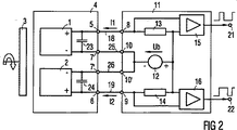
本発明では2つの位置センサ1、2が使用されて、可動対象物3の位置が測定される。この対象物は例えば磁石である。2つの位置センサは、安全関連装置の位置測定時の確実性を高めるために使用される。ここでこの安全関連装置は例えば自動車エンジンのスロットルバルブである。これらの位置センサは構成ユニットとして、プラスチック被覆部4によって取り囲まれているように射出成形されている。位置センサはそれぞれ1つの接続端子5、6および共通の接続端子7を使用することができる。回路11の相応する接続端子8、9、10と接続するために、線路18、19、20が用いられる。この回路は以降で評価回路とも称される。評価回路は動作電圧源12を含む。この動作電圧源はそれぞれ、電流測定抵抗13、14を介して接続端子8、9と、ひいては線路18、19と接続されている。測定抵抗13、14の電圧降下は、閾値特性およびヒステリシスを有する増幅器15、16に供給される。これらの増幅器の出力側21、22には、さらに使用される信号が供給される。
In the present invention, two
位置センサ1、2の接続端子には、それぞれ1つのコンデンサ23、24がブリッジ接続されており、高周波放射がフィルタリングされる。位置センサ1、2によって形成された出力信号に損害が生じないように、コンデンサ23、24は設計される。
図2に示された装置は、図1に示された装置と次の点において相違する。すなわち、共通の線路20(図1)の代わりに、それぞれ1つの線路25、26が各位置センサに使用されている点において相違する。この線路は接続端子1、10ないし7’、10’を介して、位置センサ1、2ないし回路11と接続される。このような構成によってコストは高くなるが、任意の線路に障害がある場合に、それぞれ別の位置センサが続けて完全に機能することができる。
The apparatus shown in FIG. 2 differs from the apparatus shown in FIG. 1 in the following points. That is, it differs in that one
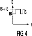
図3および4は、電流I1およびI2の経過特性を示している。これらはそれぞれ一定部分IBとパルス状部分ISから成る。一定部分は位置センサの作動に必要であり、パルス状部分は出力信号の振幅に相当する。 3 and 4 show the course characteristics of the currents I1 and I2. Each of these consists of a constant part IB and a pulsed part IS. The constant part is necessary for the operation of the position sensor, and the pulsed part corresponds to the amplitude of the output signal.
図5では、位置センサ1がより詳細に示されている。電流IBは接続端子5から、電圧安定化回路31に達する。ここでこの電圧安定化回路は元来のセンサ32および信号処理回路33に給電する。これは、電流降下部34を駆動制御するのに適した信号を生成する。これはパルス化して、電流ISを動作電流IBに接続する。
In FIG. 5, the position sensor 1 is shown in more detail. The current IB reaches the
図6は、図示されていないスロットルバルブハウジングのカバー35を示している。フランジ36によってカバー35はハウジングとねじ込み固定される。カバー35には、多重プラグ接続装置37が一体成形されている。さらに2つのプラグ接続部38、39がカバー35に設けられている。これらはハウジングの閉鎖状態で、サーボモータとプラグ接続装置37の間の接続を、妨害制止手段40、41を介して形成する。これらの妨害制止手段は、プラスチックから成るカバー35内に組み込まれている。押し抜き成形リードフレームとして構成された、プラグ接続装置37および妨害制止手段40、41の間の線路も同じように組み込まれている。
FIG. 6 shows a throttle
図示されていない、スロットルバルブの駆動接続部と並んで、カバー35内にはセンサヘッド42が配置されている。このセンサヘッドは2つの位置センサを含み、同じように、押し抜き成形リードフレーム43(図7)によって構成された、線路18、19、25、26と、プラグ接続装置37によって接続されている。この押し抜き成形リードフレーム43は同時に、プラグ接続装置37のコンタクトピン44を構成する。コンデンサ23、24は図6において、プラスチックによって射出成形被覆されずに示されている。しかし相応する前提条件のもとでは、これが射出成形被覆されていてもよい。
A
Claims (9)
前記操作部材のハウジング内に少なくとも1つの位置センサが配置されており、
当該位置センサは前記駆動接続部での位置を検出し、
少なくとも1つの位置センサ(1、2)が回路(11)と接続されており、
当該回路は動作電圧源(12)を含み、前記少なくとも1つの位置センサ(1、2)から信号を受信し、
前記回路(11)と前記少なくとも1つの位置センサ(1、2)の間の接続を、電圧および信号を伝送する線路(18、19)を介して行い、
前記回路(11)内に少なくとも1つの電流測定装置(13、15;14、16)を動作電圧源(12)に対して直列に接続し、
前記少なくとも1つの位置センサ(1,2)の信号を介して、前記操作部材の位置に依存して、電流変化を前記線路(18、19)を介して伝送する形式のものにおいて、前記2つの位置センサ(1、2)は、それぞれ1つの線路(18、19)と、1つの共通の線路(20)を介して前記回路(11)と接続されており、各位置センサ(1、2)には1つの電流測定装置(13、15;14、16)が設けられている、
ことを特徴とするセンサ装置。A sensor device for measuring the position of an operating member of an internal combustion engine, which is moved by an electric motor via a drive connection,
At least one position sensor is disposed in the housing of the operating member;
The position sensor detects the position at the drive connection,
At least one position sensor (1, 2) is connected to the circuit (11);
The circuit includes an operating voltage source (12) and receives signals from the at least one position sensor (1, 2);
A connection between the circuit (11) and the at least one position sensor (1, 2) is made via lines (18, 19) for transmitting voltages and signals;
At least one current measuring device (13, 15; 14, 16) in said circuit (11) connected in series to an operating voltage source (12);
In the type of transmitting the current change via the lines (18, 19) depending on the position of the operation member via the signal of the at least one position sensor (1, 2), the two The position sensors (1, 2) are connected to the circuit (11) via one line (18, 19) and one common line (20), respectively. Is provided with one current measuring device (13, 15; 14, 16),
A sensor device.
前記1つの電流レベルは、少なくとも1つの位置センサ(1、2)内の電圧安定化回路(31)および、前記動作電圧源(12)を流れる電流に相当し、前記1つの別の電流レベルは、信号の関数として接続可能な、位置センサ(1、2)内の負荷(34)によって高められた電流に相当する、請求項1記載のセンサ装置。The current change is binary and has one current level and one other current level;
The one current level corresponds to the current flowing through the voltage stabilization circuit (31) and the operating voltage source (12) in at least one position sensor (1, 2), and the one other current level is Sensor device according to claim 1, corresponding to a current increased by a load (34) in the position sensor (1, 2), connectable as a function of the signal.
当該2つの接続ピンは押し抜き成形リードフレームと溶着されており、当該押し抜き成形リードフレームはプラスチックから成る、ハウジングのカバー(35)内に組み込まれている、請求項1から6までのいずれか1項記載のセンサ装置。Each of the position sensors (1, 2) is configured as an integrated circuit having two connection terminal pins,
The two connecting pins are welded to the punching molded leadframe press consists of the push-out molded leadframe plastic, is incorporated into the housing of the cover (35), one of the Claims 1 to 6 The sensor device according to 1.
Applications Claiming Priority (2)
| Application Number | Priority Date | Filing Date | Title |
|---|---|---|---|
| DE102004034865A DE102004034865A1 (en) | 2004-07-19 | 2004-07-19 | Sensor for measuring the position of an actuator |
| PCT/EP2005/052794 WO2006008217A1 (en) | 2004-07-19 | 2005-06-16 | Sensor for measuring the position of an actuator |
Publications (2)
| Publication Number | Publication Date |
|---|---|
| JP2008506890A JP2008506890A (en) | 2008-03-06 |
| JP4457149B2 true JP4457149B2 (en) | 2010-04-28 |
Family
ID=35169929
Family Applications (1)
| Application Number | Title | Priority Date | Filing Date |
|---|---|---|---|
| JP2007521932A Expired - Fee Related JP4457149B2 (en) | 2004-07-19 | 2005-06-16 | Sensor for measuring the position of the operating member |
Country Status (5)
| Country | Link |
|---|---|
| US (1) | US7859250B2 (en) |
| EP (1) | EP1776518B1 (en) |
| JP (1) | JP4457149B2 (en) |
| DE (1) | DE102004034865A1 (en) |
| WO (1) | WO2006008217A1 (en) |
Families Citing this family (5)
| Publication number | Priority date | Publication date | Assignee | Title |
|---|---|---|---|---|
| DE102005016267A1 (en) | 2005-04-08 | 2006-10-12 | Siemens Ag | Sensor for measuring the position of an actuator |
| WO2013052945A2 (en) * | 2011-10-08 | 2013-04-11 | Columbus Mckinnon Corporation | Actuator control circuit |
| US9803998B1 (en) * | 2013-12-31 | 2017-10-31 | Joral Llc | Absolute position sensor with fine resolution |
| CN108122401B (en) * | 2016-11-29 | 2021-10-15 | 英飞凌科技股份有限公司 | Signal generator, decoder, method for generating a transmission signal and method for determining speed data |
| JP7293818B2 (en) | 2019-04-03 | 2023-06-20 | 株式会社プロテリアル | Sensor devices, cables with sensors and composite cables |
Family Cites Families (18)
| Publication number | Priority date | Publication date | Assignee | Title |
|---|---|---|---|---|
| US4491921A (en) * | 1980-12-23 | 1985-01-01 | Toyota Jidosha Kogyo Kabushiki Kaisha | Method and apparatus for controlling the air fuel ratio in an internal combustion engine |
| JPH0663471B2 (en) * | 1986-02-13 | 1994-08-22 | 本田技研工業株式会社 | Auxiliary air amount control device for internal combustion engine |
| FR2697585B1 (en) * | 1992-10-29 | 1995-01-06 | Solex | Motor control system with motorized throttle body. |
| DE19504822C1 (en) * | 1995-02-14 | 1996-09-26 | Hirschmann Richard Gmbh | Device for monitoring at least two state variables of a motor vehicle |
| DE19548222A1 (en) | 1995-12-22 | 1997-06-26 | Forschungszentrum Juelich Gmbh | Process for the microbial production of amino acids through increased activity of export carriers |
| DE19634714B4 (en) * | 1996-08-28 | 2007-08-16 | Continental Teves Ag & Co. Ohg | Arrangement for a motor vehicle control system |
| DE19634715A1 (en) * | 1996-08-28 | 1998-03-05 | Teves Gmbh Alfred | Arrangement for detecting the turning behavior of a wheel |
| DE19650935A1 (en) * | 1996-12-07 | 1998-06-10 | Teves Gmbh Alfred | Method and circuit arrangement for the transmission of speed information and additional data |
| JP4545954B2 (en) | 1999-05-18 | 2010-09-15 | コンティネンタル・テーベス・アクチエンゲゼルシヤフト・ウント・コンパニー・オッフェネ・ハンデルスゲゼルシヤフト | Sensor assembly device and sensor for such assembly device |
| DE19937155A1 (en) * | 1999-08-06 | 2001-03-15 | Bosch Gmbh Robert | System for generating a signal for superimposing information |
| DE19946994C2 (en) * | 1999-09-30 | 2001-09-13 | Infineon Technologies Ag | Method and timing circuit for generating a switching or control signal |
| US6498481B2 (en) * | 2000-05-13 | 2002-12-24 | Ab Eletronik Gmbh | Angel-of-rotation sensor device |
| DE20008663U1 (en) * | 2000-05-13 | 2000-08-03 | A B Elektronik Gmbh | Angle of rotation sensor |
| DE10133631A1 (en) * | 2001-07-11 | 2003-01-30 | Siemens Ag | Method for contactless detection of the position of a throttle valve shaft of a throttle valve connector and throttle valve connector |
| US6541281B2 (en) * | 2001-07-16 | 2003-04-01 | Tachyon Semiconductors Corporation | Ferroelectric circuit element that can be fabricated at low temperatures and method for making the same |
| US6638025B2 (en) | 2001-12-14 | 2003-10-28 | Caterpillar Inc | Method and apparatus for controlling a fluid actuated system |
| JP2004011406A (en) | 2002-06-07 | 2004-01-15 | Hidemi Yoshizawa | Recycled asphalt portable plant method |
| JP2006042907A (en) | 2004-07-30 | 2006-02-16 | Samii Kk | Winning device of pinball game machine |
-
2004
- 2004-07-19 DE DE102004034865A patent/DE102004034865A1/en not_active Withdrawn
-
2005
- 2005-06-16 WO PCT/EP2005/052794 patent/WO2006008217A1/en active Application Filing
- 2005-06-16 EP EP05778971A patent/EP1776518B1/en not_active Expired - Fee Related
- 2005-06-16 JP JP2007521932A patent/JP4457149B2/en not_active Expired - Fee Related
- 2005-06-16 US US11/572,364 patent/US7859250B2/en not_active Expired - Fee Related
Also Published As
| Publication number | Publication date |
|---|---|
| US7859250B2 (en) | 2010-12-28 |
| EP1776518A1 (en) | 2007-04-25 |
| US20070236223A1 (en) | 2007-10-11 |
| WO2006008217A1 (en) | 2006-01-26 |
| EP1776518B1 (en) | 2013-02-13 |
| DE102004034865A1 (en) | 2006-02-16 |
| JP2008506890A (en) | 2008-03-06 |
Similar Documents
| Publication | Publication Date | Title |
|---|---|---|
| US10215799B2 (en) | Diagnositc circuitry for powered sensor multiple unique faults diagnostics and resistive fault tolerant interface to microprocessor | |
| JP3588127B2 (en) | Electronic control method and apparatus for internal combustion engine of automobile | |
| JP4457149B2 (en) | Sensor for measuring the position of the operating member | |
| JP6353648B2 (en) | Semiconductor abnormality detection circuit | |
| CN105445525B (en) | Overcurrent detection in a current sensor having a hall sensor | |
| JP3770675B2 (en) | Throttle control device | |
| WO2018230087A1 (en) | Position sensor | |
| US11131720B2 (en) | Electronic control device | |
| CN113315501A (en) | Intelligent semiconductor switch | |
| KR100187739B1 (en) | Control system of automotive air conditioning device | |
| US11169209B2 (en) | Circuit arrangement for evaluating at least two switching states of an actuating element, method for operating a circuit arrangement and switching device | |
| US9698678B2 (en) | Circuitry and method for regulating a current for diagnosing an electromechanical load utilizing multiple current measurements | |
| KR20210142649A (en) | Automotive Sensor Assemblies | |
| WO2019111673A1 (en) | Signal output device | |
| CN108352830A (en) | Has the electronic device that secondary failure prevents circuit | |
| US7235976B2 (en) | Sensor for measuring the position of an actuating element | |
| US8698491B2 (en) | Position detecting device | |
| CN109690934A (en) | Method for powering to inductive load | |
| KR20040081176A (en) | Load failure diagnosis method and apparatus and load failure processing method and apparatus | |
| CN115656750A (en) | Power supply control device and semiconductor fault detection method | |
| US11762039B2 (en) | Electrical installation comprising a monitoring module | |
| US7239235B2 (en) | Non-contact sensor idle validation switch | |
| KR101766981B1 (en) | Intergrated sensor for detecting rotating object | |
| JP2009145181A (en) | Detection device | |
| US4808935A (en) | Electric set-point transmitter |
Legal Events
| Date | Code | Title | Description |
|---|---|---|---|
| A131 | Notification of reasons for refusal |
Free format text: JAPANESE INTERMEDIATE CODE: A131 Effective date: 20090715 |
|
| A601 | Written request for extension of time |
Free format text: JAPANESE INTERMEDIATE CODE: A601 Effective date: 20091013 |
|
| A602 | Written permission of extension of time |
Free format text: JAPANESE INTERMEDIATE CODE: A602 Effective date: 20091020 |
|
| A601 | Written request for extension of time |
Free format text: JAPANESE INTERMEDIATE CODE: A601 Effective date: 20091113 |
|
| A602 | Written permission of extension of time |
Free format text: JAPANESE INTERMEDIATE CODE: A602 Effective date: 20091120 |
|
| A521 | Request for written amendment filed |
Free format text: JAPANESE INTERMEDIATE CODE: A523 Effective date: 20091210 |
|
| TRDD | Decision of grant or rejection written | ||
| A01 | Written decision to grant a patent or to grant a registration (utility model) |
Free format text: JAPANESE INTERMEDIATE CODE: A01 Effective date: 20100108 |
|
| A01 | Written decision to grant a patent or to grant a registration (utility model) |
Free format text: JAPANESE INTERMEDIATE CODE: A01 |
|
| A61 | First payment of annual fees (during grant procedure) |
Free format text: JAPANESE INTERMEDIATE CODE: A61 Effective date: 20100208 |
|
| FPAY | Renewal fee payment (event date is renewal date of database) |
Free format text: PAYMENT UNTIL: 20130212 Year of fee payment: 3 |
|
| R150 | Certificate of patent or registration of utility model |
Ref document number: 4457149 Country of ref document: JP Free format text: JAPANESE INTERMEDIATE CODE: R150 Free format text: JAPANESE INTERMEDIATE CODE: R150 |
|
| FPAY | Renewal fee payment (event date is renewal date of database) |
Free format text: PAYMENT UNTIL: 20130212 Year of fee payment: 3 |
|
| S111 | Request for change of ownership or part of ownership |
Free format text: JAPANESE INTERMEDIATE CODE: R313113 |
|
| FPAY | Renewal fee payment (event date is renewal date of database) |
Free format text: PAYMENT UNTIL: 20130212 Year of fee payment: 3 |
|
| R350 | Written notification of registration of transfer |
Free format text: JAPANESE INTERMEDIATE CODE: R350 |
|
| FPAY | Renewal fee payment (event date is renewal date of database) |
Free format text: PAYMENT UNTIL: 20130212 Year of fee payment: 3 |
|
| RD02 | Notification of acceptance of power of attorney |
Free format text: JAPANESE INTERMEDIATE CODE: R3D02 |
|
| FPAY | Renewal fee payment (event date is renewal date of database) |
Free format text: PAYMENT UNTIL: 20140212 Year of fee payment: 4 |
|
| R250 | Receipt of annual fees |
Free format text: JAPANESE INTERMEDIATE CODE: R250 |
|
| R250 | Receipt of annual fees |
Free format text: JAPANESE INTERMEDIATE CODE: R250 |
|
| R250 | Receipt of annual fees |
Free format text: JAPANESE INTERMEDIATE CODE: R250 |
|
| R250 | Receipt of annual fees |
Free format text: JAPANESE INTERMEDIATE CODE: R250 |
|
| R250 | Receipt of annual fees |
Free format text: JAPANESE INTERMEDIATE CODE: R250 |
|
| R250 | Receipt of annual fees |
Free format text: JAPANESE INTERMEDIATE CODE: R250 |
|
| R250 | Receipt of annual fees |
Free format text: JAPANESE INTERMEDIATE CODE: R250 |
|
| LAPS | Cancellation because of no payment of annual fees |