JP4457004B2 - Catheter and introducer needle assembly with needle shield - Google Patents
Catheter and introducer needle assembly with needle shield Download PDFInfo
- Publication number
- JP4457004B2 JP4457004B2 JP2004516098A JP2004516098A JP4457004B2 JP 4457004 B2 JP4457004 B2 JP 4457004B2 JP 2004516098 A JP2004516098 A JP 2004516098A JP 2004516098 A JP2004516098 A JP 2004516098A JP 4457004 B2 JP4457004 B2 JP 4457004B2
- Authority
- JP
- Japan
- Prior art keywords
- needle
- shield assembly
- plate
- tilting
- needle shield
- Prior art date
- Legal status (The legal status is an assumption and is not a legal conclusion. Google has not performed a legal analysis and makes no representation as to the accuracy of the status listed.)
- Expired - Lifetime
Links
Images


Classifications
-
- A—HUMAN NECESSITIES
- A61—MEDICAL OR VETERINARY SCIENCE; HYGIENE
- A61M—DEVICES FOR INTRODUCING MEDIA INTO, OR ONTO, THE BODY; DEVICES FOR TRANSDUCING BODY MEDIA OR FOR TAKING MEDIA FROM THE BODY; DEVICES FOR PRODUCING OR ENDING SLEEP OR STUPOR
- A61M5/00—Devices for bringing media into the body in a subcutaneous, intra-vascular or intramuscular way; Accessories therefor, e.g. filling or cleaning devices, arm-rests
- A61M5/178—Syringes
- A61M5/31—Details
- A61M5/32—Needles; Details of needles pertaining to their connection with syringe or hub; Accessories for bringing the needle into, or holding the needle on, the body; Devices for protection of needles
- A61M5/3205—Apparatus for removing or disposing of used needles or syringes, e.g. containers; Means for protection against accidental injuries from used needles
- A61M5/321—Means for protection against accidental injuries by used needles
- A61M5/3243—Means for protection against accidental injuries by used needles being axially-extensible, e.g. protective sleeves coaxially slidable on the syringe barrel
- A61M5/3273—Means for protection against accidental injuries by used needles being axially-extensible, e.g. protective sleeves coaxially slidable on the syringe barrel freely sliding on needle shaft without connection to syringe or needle
-
- A—HUMAN NECESSITIES
- A61—MEDICAL OR VETERINARY SCIENCE; HYGIENE
- A61M—DEVICES FOR INTRODUCING MEDIA INTO, OR ONTO, THE BODY; DEVICES FOR TRANSDUCING BODY MEDIA OR FOR TAKING MEDIA FROM THE BODY; DEVICES FOR PRODUCING OR ENDING SLEEP OR STUPOR
- A61M25/00—Catheters; Hollow probes
- A61M25/01—Introducing, guiding, advancing, emplacing or holding catheters
- A61M25/06—Body-piercing guide needles or the like
- A61M25/0612—Devices for protecting the needle; Devices to help insertion of the needle, e.g. wings or holders
- A61M25/0618—Devices for protecting the needle; Devices to help insertion of the needle, e.g. wings or holders having means for protecting only the distal tip of the needle, e.g. a needle guard
- A61M25/0625—Devices for protecting the needle; Devices to help insertion of the needle, e.g. wings or holders having means for protecting only the distal tip of the needle, e.g. a needle guard with a permanent connection to the needle hub, e.g. a guiding rail, a locking mechanism or a guard advancement mechanism
-
- A—HUMAN NECESSITIES
- A61—MEDICAL OR VETERINARY SCIENCE; HYGIENE
- A61M—DEVICES FOR INTRODUCING MEDIA INTO, OR ONTO, THE BODY; DEVICES FOR TRANSDUCING BODY MEDIA OR FOR TAKING MEDIA FROM THE BODY; DEVICES FOR PRODUCING OR ENDING SLEEP OR STUPOR
- A61M5/00—Devices for bringing media into the body in a subcutaneous, intra-vascular or intramuscular way; Accessories therefor, e.g. filling or cleaning devices, arm-rests
- A61M5/178—Syringes
- A61M5/31—Details
- A61M5/32—Needles; Details of needles pertaining to their connection with syringe or hub; Accessories for bringing the needle into, or holding the needle on, the body; Devices for protection of needles
- A61M5/3205—Apparatus for removing or disposing of used needles or syringes, e.g. containers; Means for protection against accidental injuries from used needles
- A61M5/321—Means for protection against accidental injuries by used needles
- A61M5/3243—Means for protection against accidental injuries by used needles being axially-extensible, e.g. protective sleeves coaxially slidable on the syringe barrel
- A61M5/3275—Means for protection against accidental injuries by used needles being axially-extensible, e.g. protective sleeves coaxially slidable on the syringe barrel being connected to the needle hub or syringe by radially deflectable members, e.g. longitudinal slats, cords or bands
-
- A—HUMAN NECESSITIES
- A61—MEDICAL OR VETERINARY SCIENCE; HYGIENE
- A61M—DEVICES FOR INTRODUCING MEDIA INTO, OR ONTO, THE BODY; DEVICES FOR TRANSDUCING BODY MEDIA OR FOR TAKING MEDIA FROM THE BODY; DEVICES FOR PRODUCING OR ENDING SLEEP OR STUPOR
- A61M5/00—Devices for bringing media into the body in a subcutaneous, intra-vascular or intramuscular way; Accessories therefor, e.g. filling or cleaning devices, arm-rests
- A61M5/178—Syringes
- A61M5/31—Details
- A61M5/32—Needles; Details of needles pertaining to their connection with syringe or hub; Accessories for bringing the needle into, or holding the needle on, the body; Devices for protection of needles
- A61M5/3205—Apparatus for removing or disposing of used needles or syringes, e.g. containers; Means for protection against accidental injuries from used needles
- A61M5/321—Means for protection against accidental injuries by used needles
- A61M5/3243—Means for protection against accidental injuries by used needles being axially-extensible, e.g. protective sleeves coaxially slidable on the syringe barrel
- A61M5/3245—Constructional features thereof, e.g. to improve manipulation or functioning
- A61M2005/3247—Means to impede repositioning of protection sleeve from needle covering to needle uncovering position
Landscapes
- Health & Medical Sciences (AREA)
- Life Sciences & Earth Sciences (AREA)
- Engineering & Computer Science (AREA)
- Anesthesiology (AREA)
- General Health & Medical Sciences (AREA)
- Biomedical Technology (AREA)
- Heart & Thoracic Surgery (AREA)
- Hematology (AREA)
- Veterinary Medicine (AREA)
- Animal Behavior & Ethology (AREA)
- Public Health (AREA)
- Biophysics (AREA)
- Pulmonology (AREA)
- Vascular Medicine (AREA)
- Environmental & Geological Engineering (AREA)
- Infusion, Injection, And Reservoir Apparatuses (AREA)
- Media Introduction/Drainage Providing Device (AREA)
Abstract
Description
本願は、35USC119(e)に基づき、2002年6月20日提出の米国仮特許出願第60/390,499号の利益を主張する。 This application claims the benefit of US Provisional Patent Application No. 60 / 390,499 filed June 20, 2002, based on 35 USC 119 (e).
本願は、次の先願に関連されており、各先願は参照により組み込まれる。本願は、2002年12月17日提出の米国特許出願第10/320,960号の一部継続出願であり、これは2000年2月4日提出の米国特許出願第09/499,331号の継続出願であり、これは1999年5月14日提出の米国特許出願第09/312,335号(米国特許第6,379,333号)の一部継続出願であり、これは1998年4月8日提出の米国特許出願第09/057,718号(米国特許第6,004,294号)の一部継続出願である。 This application is related to the following prior applications, each prior application being incorporated by reference. This application is a continuation-in-part of US patent application Ser. No. 10 / 320,960, filed on Dec. 17, 2002, which is a continuation of US patent application Ser. No. 09 / 499,331, filed Feb. 4, 2000. This is a continuation application, which is a continuation-in-part of US patent application Ser. No. 09 / 312,335 (US Pat. No. 6,379,333) filed May 14, 1999, which was issued in April 1998. This is a continuation-in-part of US Patent Application No. 09 / 057,718 (US Pat. No. 6,004,294) filed on the 8th.
また、本願は、2000年11月21日提出の米国特許出願第09/717,148号の一部継続出願であり、これは放棄された米国特許出願第09/590,600号の一部継続出願であり、これは1999年5月14日提出の米国特許出願第09/312,335号(米国特許第6,379,333号)の一部継続出願であり、これは1998年4月8日提出の米国特許出願第09/057,718号(米国特許第6,004,294号)の一部継続出願である。 This application is a continuation-in-part of US patent application Ser. No. 09 / 717,148 filed Nov. 21, 2000, which is a continuation of a part of abandoned US patent application No. 09 / 590,600. This is a continuation-in-part application of US patent application Ser. No. 09 / 312,335 (US Pat. No. 6,379,333) filed May 14, 1999, which was issued on April 8, 1998. This is a continuation-in-part of U.S. patent application Ser.
本発明は、ニードルのシャープな遠位端を安全にシールドすると共に、先端がシールドされた後、ニードル先端の遠位方向の移動を、傾く又は「傾動する(canting)」板によって、制限するように構成されたニードルシールドアッセンブリに関するものである。 The present invention safely shields the sharp distal end of the needle and limits the distal movement of the needle tip after the tip is shielded by a tilted or “canting” plate. The present invention relates to a needle shield assembly configured as described above.
ノーマルセーライン溶液(normal saline solution)、種々の薬剤、及びトータルな非経口栄養(total parenteral nutrition)等の流体を患者に導入し、又は患者から血液を抜き取るため、静脈(IV)カテーテルが用いられる。周辺IVカテーテル(peripheral IV catheter)は、比較的短くなる傾向にあり、長さにおいて約1及び1.5インチ(25.4及び38.1ミリメートル)のオーダーである。共通タイプのIVカテーテルは、オーバー・ザ・ニードル(over the needle)周辺IVカテーテルである。その名が示す通り、オーバー・ザ・ニードルカテーテルは、シャープな遠位端を有するイントロデューサニードルに被さって取り付けられる(mounted over an introducer needle)。カテーテルとイントロデューサニードルとは、イントロデューサニードルの遠位端がカテーテルの遠位端を越えて延在し、ニードルの斜面が患者の皮膚から離れて上向くように、組み立てられる。 Intravenous (IV) catheters are used to introduce fluids such as normal saline solution, various drugs, and total parenteral nutrition into the patient, or withdraw blood from the patient. . Peripheral IV catheters tend to be relatively short, on the order of about 1 and 1.5 inches (25.4 and 38.1 millimeters) in length. A common type of IV catheter is an over the needle peripheral IV catheter. As the name implies, an over-the-needle catheter is mounted over an introducer needle having a sharp distal end. The catheter and introducer needle are assembled such that the distal end of the introducer needle extends beyond the distal end of the catheter and the bevel of the needle faces away from the patient's skin.
カテーテル及びイントロデューサニードルアッセンブリは、浅い角度で患者の皮膚を通過し、周辺血管(即ち、心臓に直接接続されていないが、心臓に直接接続された中心血管の枝官の一つである小血管)に挿入される。静脈におけるアッセンブリの適切な配置を確かめるため、医者は、ニードル内に、及びニードルの近位端に位置されたフラッシュバックチャンバ内に、血液のフラッシュバック(逆流;flashback)があることを確認する。典型的に、フラッシュバックチャンバはニードルハブの一部として形成される。適切な配置が確認されると、医者は、イントロデューサニードルの遠位端及びカテーテル付近の患者の皮膚に押し下げることにより、血液容器に圧力を加える。この指圧はイントロデューサニードルを通ずるさらなる血流を妨げる。医者はイントロデューサニードルを引き抜き、カテーテルを定位置に残し、流体処理装置をカテーテルハブに取り付ける。イントロデューサニードルがカテーテルから引き抜かれれば、それは「血液汚染された鋭利物(blood contaminated sharp)」と考えられ、適切に取り扱われなければならない。 The catheter and introducer needle assembly passes through the patient's skin at a shallow angle and is a small blood vessel that is one of the branches of the surrounding blood vessels (ie, not directly connected to the heart but directly connected to the heart). ) Is inserted. To ascertain proper placement of the assembly in the vein, the physician verifies that there is a flashback of blood in the needle and in the flashback chamber located at the proximal end of the needle. Typically, the flashback chamber is formed as part of the needle hub. Once proper placement is confirmed, the physician applies pressure to the blood container by pushing down the distal end of the introducer needle and the patient's skin near the catheter. This finger pressure prevents further blood flow through the introducer needle. The physician pulls out the introducer needle, leaves the catheter in place, and attaches the fluid treatment device to the catheter hub. If the introducer needle is withdrawn from the catheter, it is considered “blood contaminated sharp” and must be handled appropriately.
近年、患者の血液による医者の汚染と、「血液汚染された鋭利物」が即座に廃棄されなければならないという認識とに関する多くの関心がある。この関心は、感染者から他人への体液の交換によって移され得る病気を広めることに関するリスクを、いくぶん、減少するために高まっている。結局、感染者の体液との接触は避けるのが望ましい。様々なニードルシールドが開発されている。概して、この種のニードルシールドはそれらの予定された目的のために作動するが、改良されることができる。例えば、幾つかのニードルシールドはがさばり、使用が困難であったり、適切に作動されるための特別の要素又は技術を必要とする。 In recent years, there has been much interest in the contamination of doctors with patient blood and the recognition that “blood-contaminated sharps” must be discarded immediately. This interest has increased to somewhat reduce the risks associated with spreading illness that can be transferred by the exchange of fluid from one infected person to another. After all, it is desirable to avoid contact with body fluids of infected people. Various needle shields have been developed. In general, this type of needle shield operates for their intended purpose, but can be improved. For example, some needle shields are bulky, difficult to use, and require special elements or techniques to operate properly.
本発明の一形態によれば、オーバー・ザ・ニードルカテーテルアッセンブリは、カテーテルアダプタとニードルとを含む。ニードルは直径と遠位端とを有し、カテーテルアダプタ内にスライド可能に配置される。ニードルシールドアッセンブリはニードルにスライド可能に取り付けられる。ニードルシールドアッセンブリは開放遠位端と開放近位端とを有し、これらをニードルが通過する。「傾動板(canting plate)」と称される剛体板が、ニードルシールドアッセンブリ内に配置されると共に、非作動第1位置と作動第2位置とを有する。第2位置において、傾動板はニードルの動きを制限する。傾動板を保持するための手段が設けられる。傾動板保持手段は傾動板に接続し、ニードルの近位方向の移動に反応する。これにより、ニードル先端がニードルシールドアッセンブリ内に収容されたとき、傾動板保持手段は作動され、ニードルの遠位方向の動きを生じさせ、傾動板を非作動第1位置から作動第2位置へと付勢する。 According to one aspect of the invention, an over-the-needle catheter assembly includes a catheter adapter and a needle. The needle has a diameter and a distal end and is slidably disposed within the catheter adapter. The needle shield assembly is slidably attached to the needle. The needle shield assembly has an open distal end and an open proximal end through which the needle passes. A rigid plate referred to as a “canting plate” is disposed within the needle shield assembly and has a non-actuated first position and an actuated second position. In the second position, the canting plate limits the movement of the needle. Means are provided for holding the canting plate. The canting plate holding means is connected to the canting plate and is responsive to the proximal movement of the needle. Thus, when the needle tip is housed in the needle shield assembly, the tilting plate holding means is actuated, causing the needle to move in the distal direction, and the tilting plate is moved from the non-operating first position to the operating second position. Energize.
本発明のこの形態のある実施例によれば、傾動板保持手段はスプリング、保持アーム及び保持ワッシャを備える。スプリングは、コイルスプリング、波ワッシャ及びリーフスプリング等からなるグループから選択されてもよい。ニードルシールドアッセンブリは、傾動板保持手段に反応する複数の傾動板を有していても良い。傾動板保持手段は、傾動板保持アームと、傾動板に取り付けられビルトインスプリングを有する保持ワッシャとを含んでもよい。保持ワッシャはシールド内に全体的に収容されてもよい。傾動板保持手段は弾性ワッシャと整列アームとを含んでもよい。弾性ワッシャは切頭状の(truncated)遠位端を有してもよい。カテーテルアダプタとシールドとはインターロック(interlock)により共に保持されてもよい。静止要素(static feature)がニードルに設けられてもよく、これにおいて、インターロックは、ニードルの静止要素がシールド近位端に接触する前又はそれと実質的に同時に、解放される。ニードル先端と静止要素との間の距離は、静止要素がシールド近位端に接触したときニードル先端がシールド内に収容されるような距離である。傾動板は、ニードルの通過のための穴を含んでもよく、またシールドの近位端の遠位側に位置されてもよい。傾動板は、ニードルが遠位方向に付勢されないときに非作動位置に戻されてもよい。 According to one embodiment of this aspect of the invention, the tilting plate holding means comprises a spring, a holding arm and a holding washer. The spring may be selected from the group consisting of a coil spring, a wave washer, a leaf spring, and the like. The needle shield assembly may have a plurality of tilt plates that react to the tilt plate holding means. The tilting plate holding means may include a tilting plate holding arm and a holding washer attached to the tilting plate and having a built-in spring. The retaining washer may be entirely contained within the shield. The tilting plate holding means may include an elastic washer and an alignment arm. The elastic washer may have a truncated distal end. The catheter adapter and shield may be held together by an interlock. A static feature may be provided on the needle, wherein the interlock is released before or substantially simultaneously with the needle's stationary element contacting the shield proximal end. The distance between the needle tip and the stationary element is such that the needle tip is received within the shield when the stationary element contacts the shield proximal end. The canting plate may include a hole for the passage of the needle and may be located distal to the proximal end of the shield. The canting plate may be returned to the inoperative position when the needle is not biased in the distal direction.
本発明の他の形態によれば、前述のオーバー・ザ・ニードルカテーテルが次の方法に従って使用されてもよい。即ち、この方法は、静止要素がニードルシールドの近位端に接触するまでニードルを近位方向に引くことと、ニードル先端がシールド内にあることを確認することと、ニードルを遠位方向に付勢して傾動板をロックさせ、さらなる遠位方向の移動を規制することとを含む。 According to another aspect of the invention, the aforementioned over-the-needle catheter may be used according to the following method. That is, the method pulls the needle proximally until the stationary element contacts the proximal end of the needle shield, verifies that the needle tip is within the shield, and attaches the needle distally. Forcing the canting plate to lock and restricting further distal movement.
本発明の一形態によれば、ニードルをシールドするための装置が設けられ、装置はハウジングを含む。ニードルシールドアッセンブリは、ハウジング内のアンロック位置及びハウジング外のロック位置から移動可能である。ニードルシールドアッセンブリはシールド本体を含み、シールド本体は側壁、近位端及び遠位端を有する。傾動部材は、整列状態から非整列状態への移動のためにシールド本体内に配置される。スプリングがシールド本体及び傾動部材に作動可能に係合され、傾動部材を非整列状態に付勢する。保持アームが、シールド本体に係合されると共に、係合位置から非係合位置に変位可能である。ニードルシールドアッセンブリがハウジング内にあるとき、ハウジングは保持アームを係合位置に変位させ、このとき保持アームは傾動部材に係合し、傾動部材を整列状態に維持する。ニードルシールドがハウジング外にあるとき、保持アームは非係合位置に移動し、このとき保持アームは傾動部材から離脱し、傾動部材はスプリングによって非整列状態に変位される。 In accordance with one aspect of the invention, an apparatus for shielding a needle is provided, the apparatus including a housing. The needle shield assembly is movable from an unlocked position within the housing and a locked position outside the housing. The needle shield assembly includes a shield body that has a sidewall, a proximal end, and a distal end. The canting member is disposed within the shield body for movement from the aligned state to the non-aligned state. A spring is operatively engaged with the shield body and the tilting member to bias the tilting member out of alignment. The holding arm is engaged with the shield body and is displaceable from the engagement position to the non-engagement position. When the needle shield assembly is in the housing, the housing displaces the holding arm to the engaged position, wherein the holding arm engages the tilting member and maintains the tilting member in alignment. When the needle shield is outside the housing, the holding arm moves to the disengaged position, at which time the holding arm is disengaged from the tilting member, and the tilting member is displaced into a non-aligned state by the spring.
本発明の形態のある実施例では、傾動部材が傾動板である。スプリングは、傾動部材に一体的に形成されたリーフスプリングであってもよい。シールド本体、傾動板及びスプリングは一体的に形成されてもよい。シールド本体は、その近位端に配置された保持ワッシャを含んでもよく、保持ワッシャは、ニードルが通過する開口を区画する。 In one embodiment of the present invention, the tilting member is a tilting plate. The spring may be a leaf spring formed integrally with the tilting member. The shield body, the tilting plate, and the spring may be integrally formed. The shield body may include a retaining washer disposed at a proximal end thereof that defines an opening through which the needle passes.
前述の装置は、ニードルの本体より大きい直径を有する要素を含むニードルと共に用いられてもよい。保持ワッシャの開口は、ニードル本体の通過を許容するがその要素の通過を阻止するサイズとされる。シールド本体は保持アームを含んでもよい。保持アームは、ニードルシールドアッセンブリがハウジング内にあるとき、半径方向内側に付勢されて傾動部材に係合し、ニードルシールドアッセンブリがハウジング外にあるとき、半径方向外側に移動して傾動部材から離脱する。シールド本体はレッジ(ledge)を含んでもよく、レッジは保持アームの反対側に配置され、傾動部材に隣接する。レッジは側壁に一体的に形成されてもよい。 The aforementioned device may be used with a needle that includes an element having a larger diameter than the body of the needle. The opening in the retaining washer is sized to allow passage of the needle body but prevent passage of the element. The shield body may include a holding arm. The holding arm is biased radially inward to engage the tilting member when the needle shield assembly is in the housing, and moves radially outward to disengage from the tilting member when the needle shield assembly is outside the housing. To do. The shield body may include a ledge, the ledge being disposed on the opposite side of the holding arm and adjacent to the tilting member. The ledge may be formed integrally with the side wall.
本発明の他の形態によれば、ニードルシールドアッセンブリがシールド本体を含み、シールド本体は側壁、近位端及び遠位端を有する。弾性ワッシャ等の部材が、ハウジング内に配置されると共に、中心空所を有する。空所は、ニードルと摩擦的に係合するサイズとされる。傾動部材が、シールド本体内に配置されると共に、整列状態と非整列状態との間を移動可能である。この部材は、ニードルがシールド本体に対し近位方向に移動されたとき、ニードルが部材を変形させ、これが傾動部材を非整列状態に変位させるように、傾動部材に選択的に係合される。 According to another aspect of the invention, a needle shield assembly includes a shield body, the shield body having a side wall, a proximal end, and a distal end. A member such as an elastic washer is disposed within the housing and has a central cavity. The void is sized to frictionally engage the needle. A tilt member is disposed within the shield body and is movable between an aligned state and an unaligned state. The member is selectively engaged with the canting member such that when the needle is moved proximally with respect to the shield body, the needle deforms the member, which displaces the canting member in an unaligned state.
本発明のこの形態のある実施例では、部材が弾性部材であって傾動部材が傾動板である。傾動部材を整列状態に保持するための手段が設けられてもよい。整列アームが、シールド本体に取り付けられると共に、傾動部材に隣接する。部材は、傾動部材と、シールド本体の近位端とに隣接する弾性ワッシャである。部材は傾動部材に恒久的かつ直接的に取り付けられる。レッジがシールド本体に固定して取り付けられてもよく、傾動部材の遠位側に配置されて傾動部材に隣接しても良い。インターロックフランジが、シールド本体の遠位端に設けられてもよく、アダプタリリースがシールド本体内にスライド可能に配置されてもよい。アダプタリリースはリリースピンを含み、リリースピンは、傾動板が整列状態にあるときインターロックフランジに係合し、インターロックフランジをカテーテルアダプタと係合するよう付勢する。 In an embodiment of this aspect of the invention, the member is an elastic member and the tilting member is a tilting plate. Means may be provided for holding the tilting member in alignment. An alignment arm is attached to the shield body and is adjacent to the canting member. The member is an elastic washer adjacent to the tilting member and the proximal end of the shield body. The member is permanently and directly attached to the tilting member. The ledge may be fixedly attached to the shield body, or may be disposed on the distal side of the tilting member and adjacent to the tilting member. An interlock flange may be provided at the distal end of the shield body and the adapter release may be slidably disposed within the shield body. The adapter release includes a release pin that engages the interlock flange when the canting plate is in alignment and biases the interlock flange to engage the catheter adapter.
本発明の他の形態によれば、カテーテルアッセンブリが、カテーテルアダプタと、先端を有するニードルとを含んで設けられる。要素が、先端から選択された距離の位置にニードルに設けられる。ニードルシールドアッセンブリはニードルの周りにスライド可能に配置される。ニードルシールドアッセンブリは側壁、近位端及び遠位端を有する。インターロックフランジが、シールド本体の遠位端の位置に設けられると共に、半径方向外側に付勢される。アダプタリリースが、遠位位置から近位位置への移動のため、シールド本体内にスライド可能に配置される。アダプタリリースはリリースピンを含み、リリースピンは、アダプタリリースが遠位位置にあるとき、インターロックフランジに係合する。傾動板が、ハウジング内に保持されると共に、エッジによって区画される開口を含む。ニードルが開口内にスライド可能に配置される。傾動板は、ニードルがエッジからの干渉無く通過する整列位置から、エッジがニードルに巻き付く非整列位置へと、移動可能である。摩擦部材が、ハウジング内に移動可能に配置されると共に、ニードルに摩擦係合される。アダプタリリースが遠位位置にあるとき、それはインターロックフランジをカテーテルアダプタと係合するよう付勢する。逆に、アダプタリリースが近位位置にあるとき、インターロックフランジはカテーテルアダプタとの係合から解放される。ニードルがニードルシールドアッセンブリに対し近位方向に変位されたとき、摩擦部材が変位され、傾動板を非整列位置に動かす。 According to another aspect of the invention, a catheter assembly is provided including a catheter adapter and a needle having a tip. An element is provided on the needle at a selected distance from the tip. The needle shield assembly is slidably disposed about the needle. The needle shield assembly has a side wall, a proximal end and a distal end. An interlock flange is provided at the distal end of the shield body and biased radially outward. An adapter release is slidably disposed within the shield body for movement from the distal position to the proximal position. The adapter release includes a release pin that engages the interlock flange when the adapter release is in the distal position. A canting plate is held in the housing and includes an opening defined by an edge. A needle is slidably disposed within the opening. The canting plate is movable from an aligned position where the needle passes without interference from the edge to an unaligned position where the edge wraps around the needle. A friction member is movably disposed within the housing and frictionally engaged with the needle. When the adapter release is in the distal position, it biases the interlock flange into engagement with the catheter adapter. Conversely, when the adapter release is in the proximal position, the interlock flange is released from engagement with the catheter adapter. When the needle is displaced proximally with respect to the needle shield assembly, the friction member is displaced and moves the canting plate to the non-aligned position.
本発明の他の形態によれば、先端及びニードル軸を有するニードルのためのニードルシールドアッセンブリが設けられる。特に、ハウジングは近位端と遠位端とを有する。摩擦部材が、ハウジング内に配置されると共に、ニードルに摩擦係合される。傾動部材が、ハウジング内に配置されると共に、部材開口を区画するエッジを含む。傾動部材は、部材開口がニードル軸に整列される第1位置から、エッジがニードルにロックして係合する第2位置へと移動可能である。摩擦部材が傾動部材に作動可能に係合され、摩擦部材の移動は傾動部材を第2位置に変位させる。 According to another aspect of the invention, a needle shield assembly is provided for a needle having a tip and a needle shaft. In particular, the housing has a proximal end and a distal end. A friction member is disposed in the housing and frictionally engaged with the needle. A tilting member is disposed within the housing and includes an edge that defines a member opening. The tilting member is movable from a first position where the member opening is aligned with the needle axis to a second position where the edge locks and engages the needle. The friction member is operatively engaged with the tilt member, and movement of the friction member displaces the tilt member to the second position.
本発明のこの形態のある実施例では、保持ワッシャがハウジングの近位端の位置に位置され、選択された穴サイズを有する穴が保持ワッシャに配置される。 In certain embodiments of this aspect of the invention, a retaining washer is positioned at the proximal end of the housing and a hole having a selected hole size is disposed in the retaining washer.
本発明の他の形態によれば、ニードルをシールドするための方法が提供される。傾動部材がニードルと作動可能に係合される。傾動部材は、傾動部材がニードルに係合しない第1位置から、傾動部材がニードルに巻き付く第2位置へと、ニードルに対して変位可能である。作動部材がニードルと摩擦係合される。ニードルは、作動部材が変位されるよう、傾動部材に対して変位される。傾動部材は、作動部材が変位されたとき、作動部材によって第2位置に移動される。本発明のこの形態のある実施例では、作動部材とニードルとの間の摩擦が作動部材をニードルと共に変位させ、或いは、作動部材が傾動部材に直接作用する。 In accordance with another aspect of the invention, a method for shielding a needle is provided. A tilting member is operatively engaged with the needle. The tilt member is displaceable relative to the needle from a first position where the tilt member does not engage the needle to a second position where the tilt member wraps around the needle. The actuating member is frictionally engaged with the needle. The needle is displaced relative to the tilting member so that the actuating member is displaced. The tilting member is moved to the second position by the actuating member when the actuating member is displaced. In certain embodiments of this aspect of the invention, friction between the actuating member and the needle displaces the actuating member with the needle, or the actuating member acts directly on the tilting member.
本発明によれば、改良された好適なニードルシールドアッセンブリ及びこれを備えたカテーテル及びイントロデューサニードルアッセンブリを提供することができるという、優れた効果が発揮される。 According to the present invention, it is possible to provide an improved advantageous needle shield assembly, a catheter equipped with the needle shield assembly, and an introducer needle assembly.
ここで使用されるように、用語「近位(proximal)」とは、本発明のカテーテル及びニードルシールドアッセンブリにおける位置であって、通常使用時に、装置を使用する医者に最も近く、装置が使用される患者から最も遠い位置のことをいう。逆に、用語「遠位(distal)」とは、本発明のカテーテル及びニードルシールドアッセンブリにおける位置であって、通常使用時に、装置を使用する医者から最も遠く、装置が使用される患者に最も近い位置のことをいう。 As used herein, the term “proximal” is a position in the catheter and needle shield assembly of the present invention that, in normal use, is closest to the physician using the device and the device is used. The farthest position from the patient. Conversely, the term “distal” is a position in the catheter and needle shield assembly of the present invention that, in normal use, is furthest from the doctor using the device and closest to the patient in which the device is used. It refers to the position.
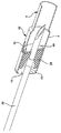
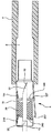
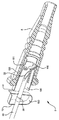
カテーテルアッセンブリ100はカテーテルアダプタ8を含むことができる。カテーテルアダプタ8は、その遠位端に取り付けられたカテーテル108を有する。ウイング130がアダプタ8に設けられても良い。使用前及び挿入中(図1に描かれる如く)、ニードル30はカテーテル内に配置され、先端又は遠位点32が、カテーテルの遠位端から突出する。ニードルの近位端はニードルハブ110に取り付けられる。フィンガーグリップ120がニードルハブ110に含まれても良い。参照により本願に組み込まれる米国特許出願第09/865,915号明細書(2001年5月25日提出)に述べられているように、この種の構造は、ウイング130と関連して、介護者がカテーテル挿入のための様々なテクニックを用いるのを許容する。
図1に示されるように、ニードルシールドアッセンブリ5は、ニードルの周りに、ニードルハブ110とカテーテルアダプタ8との間に配置されている。或いは、とりわけ図2A及び図2Bに示されるように、ニードルシールドアッセンブリ5は、カテーテルアダプタの中に完全に配置されてもよく、これも本発明の実施形態である。本発明の実施形態が、カテーテルアダプタの中にあるニードルシールドアッセンブリ、ニードルハブとカテーテルアダプタとの間に配置されているニードルシールドアッセンブリ、又はニードルに沿った他の位置にあるニードルシールドアッセンブリと共に実施され得ることが認識されるであろう。また、本発明の実施形態は、注射器や血液採集器等の他の装置に使用されるニードル及び鋭利物と共に用いられても良い。
As shown in FIG. 1, the
後により完全に説明されるように、ニードルシールドアッセンブリ5の実施形態は、オーバー・ザ・ニードルカテーテル108の患者への挿入後、ニードル30が引き抜かれるとき、ニードルの先端32がニードルシールドアッセンブリに進入するように設計されている。この点において、ニードルシールドアッセンブリはニードル先端上にロックし、ニードルに沿ったシールドアッセンブリのさらなる移動を防止する。このように、ニードルシールドアッセンブリは、ニードルの先端から容易にすべり外したり取り外したりすることができない。加えて、ニードルシールドアッセンブリがニードル先端上にロックしているとき、それはニードルシールドアッセンブリの遠位端からの先端の再出現を防止する。
As will be more fully described later, embodiments of the
このニードルシールドアッセンブリ5とニードル30との間のロックを達成するため、ニードルシールドアッセンブリは、傾動部材又は傾動板40を含む。この傾動部材又は傾動板40の動作は、ニードルシールドアッセンブリに対して妨げられる。好ましくは、傾動部材は、ニードルシールドアッセンブリ内に収容される剛体板である。傾動板の穴42がエッジ43によって区画される。ニードルは、傾動板の穴42を挿通する。アンロック状態(例えば図2Aに見られる)において、傾動板は、保持装置又は傾動板保持手段によって、ニードルと整列された位置に保持され、これによってニードルは、実質的な干渉無く傾動板を通過する。後により完全に説明されるように、傾動板保持手段は、固定構造と可動要素との組合せ、スプリング及び・又は摩擦部材を含んでもよく、これらは協働して傾動板の位置をコントロールする。ニードルの先端32がニードルシールドアッセンブリ内に引かれると、傾動板保持手段はトリガー作動され(triggered)、傾動板を「非整列」又は「作動」状態とする。傾動板は、それがニードルの外面に巻き付き、傾動板に対するニードルの相対移動を防止するように、傾動される。傾動板がニードルシールドアッセンブリに対しても拘束されるので、ニードルとその先端とは、ニードルシールドアッセンブリに対しても拘束され、これによりニードル先端をニードルシールドアッセンブリ内でロックする。ニードルシールドアッセンブリがニードル先端からすべり外れるのを一層防止するため、要素35がニードルに設けられても良い。ニードルシールドアッセンブリがニードル先端からすべり外れるのを防止するため、つなぎひも(テザー;tether)400が設けられることもできる。後述されるように、要素及びつなぎひもは、ニードルハブ110が近位方向に動かされるとき、ニードルシールドアッセンブリをカテーテルアダプタ8から引き抜く役割を果たすこともできる。いったん定位置にロックされれば、シールドされたニードルは廃棄されることができる。
In order to achieve a lock between the
一体スプリングを備えた保持ワッシャ
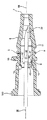
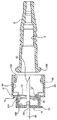
ここで図2A〜図3Bを参照すると本発明の一実施形態が示されている。図2A及び図3Aは、ニードル30がニードルシールドアッセンブリ5内に部分的に引き抜かれているが、ニードルシールドアッセンブリが作動され又はニードル上にロックされる前を描いている。図2B及び図3Bは、作動され、ニードル上にロックされた後のニードルシールドアッセンブリを描いている。アンロック又は非作動状態において(図2A及び図3A)、ニードルシールドアッセンブリ5はカテーテルアダプタ(又は単に「アダプタ」)8内に位置される。明瞭化のためカテーテル108は省略されている。図1に見られるように、使用前にカテーテルがカテーテルアダプタの遠位端に固定され、ニードルがカテーテルを同軸に挿通することが認識されるであろう。アダプタ8は内部チャンバを含み、内部チャンバはシールドハウジング6を形成し、シールドハウジング6の中にニードルシールドアッセンブリ5が着座する。シールドハウジングはアダプタから独立した構造物であっても良い。ニードルシールドアッセンブリはシールド本体10を有し、シールド本体10は側壁9及び遠位端11及び近位端12を含む。典型的に、側壁は、シールドハウジング内にぴったりと嵌まる円筒状である。側壁は、カテーテルアダプタ内への嵌合を達成する他の形状を有しても良い。シールド端11,12は、遠位端における遠位開口13と、近位端における近位開口14とを含む。
Retaining washer with integral spring Referring now to FIGS. 2A-3B, one embodiment of the present invention is shown. 2A and 3A depict the
ニードル30は、遠位のニードル点又は先端32と軸99とを有すると共に、アダプタ8内に配置されて、使用前にシールドアッセンブリ5を挿通する。特に、ニードルはシールド開口13,14を挿通し、アダプタ8の遠位端7から突出し、オーバー・ザ・ニードルカテーテル108を通じて伸びる(明瞭化のため図2A〜図3Bには示されていない)。ニードル直径は、シールド本体10の遠位開口13及び近位開口14を干渉無く挿通するサイズとされる。
The
本発明のある実施形態に関し、静止要素(static feature)35もまた、先端32から選択された距離だけ離れた位置のニードル30に設けられる。例えば参照によりともに本願に組み込まれる特許文献3及び4に開示されているように、静止要素35は、それがシールド本体10の近位開口14を挿通できぬように設計されている。静止要素は、ニードル30の拡径部(即ち、かしめ(crimp)、カラー、拡径スリーブ又はフェルール等により形成された拡大寸法)であることができ、又はニードルシールドアッセンブリ5の近位端12にロックする粗い表面であることができる。シールドの近位端からのニードル先端の脱出を制限するために他の構造が採用されることができ(例えば後述するつなぎひも)、このような構造も本発明の実施形態である。
For certain embodiments of the present invention, a
ニードルシールドアッセンブリ5は、シールド本体10内でのニードル30の軸方向移動を防止する傾動板40を含むシールド機構を収容する。傾動板は、エッジ43によって区画される穴42を含み、これをニードルが挿通する。ニードルシールドアッセンブリの近位端12は保持ワッシャ15を形成する。保持ワッシャは一端(図2Aに見られるように頂部)において側壁9に取り付けられる。スプリング45が、保持ワッシャの他端に取り付けられる。図2B及び図3Bに示されるように、スプリングは傾動板に係合し、それを非整列位置(即ち、作動又はロック位置)に付勢する。示されるように、保持ワッシャとスプリングとは一体に形成されている。これらの部品が別個に形成され、溶接等によって取り付けられ得ることが認識されるであろう。
The
ニードルシールドアッセンブリ5は保持アーム16をも含む。好ましくは、保持アームは、側壁9に一体に形成され近位端にリップ127を含むリーフスプリングである。勿論、他の構造が採用可能であり、このような構造も本発明の実施形態であり得る。図2Bに見られるように、保持アームはニードルシールドアッセンブリから半径方向外側に付勢される。ニードルシールドアッセンブリがシールドハウジング6内に位置されているとき、シールドハウジングは保持アームを図2Aに見られるように半径方向内側に押す。後述されるように、保持アームは、ニードルシールドアッセンブリがシールドハウジング内にある間に傾動板40をニードルに整列された位置(即ち、非作動又はアンロック位置)に維持するのを助ける。
ニードルシールドアッセンブリ5は、保持アーム16から離れて側壁9に形成されたレッジ(棚部;ledge)27を含む。示されるように、レッジは、側壁の一部を半径方向内側に突出するように変形させることにより形成される。レッジが他の方法(例えば、別個のレッジ構造を側壁の内側に固着させることにより、或いは側壁に出っ張りを作るかしめ等により)で形成され得ることが認識されるであろう。重要なのは、傾動板の一部がニードルシールドアッセンブリに対し動くのを防止するストッパをレッジがなすことである。
The
図2A〜図3Bのニードルシールドアッセンブリ5の作動がここで説明される。図2Aを参照して、整列又はアンロック状態において、傾動板40は保持装置、特にスプリング45、保持アーム16のリップ127及びレッジ27の協働によって定位置に保持される。スプリングは傾動板の頂部を遠位方向(図2Aにおける右側)に付勢する。ニードルシールドアッセンブリがカテーテルアダプタ8のシールドハウジング6内に位置されているとき、傾動板の頂部に係合する保持アームのリップと、傾動板の底部に係合するレッジとによって、傾動板の回転及び移動が防止される。こうして傾動板は整列状態に維持され、ニードルは、エッジ43に実質的に係合すること無く、傾動板の穴42を自由に通過できる。
Operation of the
患者の静脈への挿入後、ニードル30はカテーテル108及びカテーテルアダプタ8を通じて引き抜かれる。ニードルの要素35はニードルシールドアッセンブリ5の近位端12に係合する。図2B及び図3Bに示されるように、ニードルの要素35は、保持ワッシャの穴14に嵌まらない。結果として、介護者がニードルをカテーテルアダプタ8を通して引き抜くと、ニードルシールドアッセンブリ5の全体がシールドハウジング6から引き出される。ニードルシールドアッセンブリの取り外し時、保持アーム16はその自然のバイアス(傾き;bias)へと倒れ、半径方向外側に移動し、これによってリップ127は傾動板40の頂部から離脱する。いったん離脱されると、傾動板はスプリング45の付勢下で回転可能となる。傾動板が回転すると、穴42のエッジ43がニードル30の外面に巻き付く。傾動板は、ニードル、レッジ127及びスプリング45の協働により、このロック状態に保持される。ニードル先端をニードルシールドアッセンブリから再出現させようとしてニードルが遠位方向に押された場合、ニードル上の摩擦(傾動板を遠位方向に付勢する)とレッジ(傾動板の底部の移動を規制する)とは、傾動板をニードルに対しよりきつく傾けさせ、傾動板とニードルとの間の拘束力を増加させ、これによりそのような動きに抵抗する。これも認識されるであろうが、要素35は、傾動板が非整列(off alignment)であるときに傾動板の穴に嵌まらぬようなサイズとされても良い。これはニードル先端の再出現に対するさらなる抵抗を提供するであろう。
After insertion into the patient's vein,
図3Aに見られたように、傾動板40は、その中心部を通過する穴42を有する剛体ディスクであっても良い。示されるように、傾動板40は実質的に円形であるが、正方形、長方形、三角形、楕円形、対称形状、非対称形状等の様々な他の形状であることができる。傾動板40の中心の穴42は、好ましくはこれを通ずるニードル30と実質的に同じ形状である。しかしながら、長方形、三角形又は楕円形又は他の様々な形状等の他の穴形状が採用されることができ、このような形状も本発明の実施形態である。さらに、傾動板は平らである必要はない。それは与えられた用途のため、湾曲、段付き形状等とされることができる。
As can be seen in FIG. 3A, the
傾動板40の穴42は、ニードルのジオメトリ及び傾動板のジオメトリを考慮してニードル30への適切な締付力を得るようなサイズとされる。特に、穴は、要素35の最大直径より少なくとも大きくあるべきであり(要素がニードルの拡径部である場合)、ある実施においては、ニードル30の静止要素35の直径より約100%大きくなるよう増大してもよい。他のある用途において、穴は、ニードル30の静止要素35の最大直径より僅かに大きいサイズから、ニードル30の静止要素35の最大直径より約10〜30%大きいサイズまでの間のサイズであるのが好ましい。さらに他の用途において、穴は、ニードルシールドアッセンブリのジオメトリを考慮して、傾動板が軸99に垂直な方向から0°〜45°傾いたときそれがニードルに係合するようなサイズとされるのが望ましい。認識されるであろうが、傾動角は、傾動板、ニードルシールドアッセンブリ及びニードルのジオメトリ及び材料と、望まれる締付力とに基づいて選択されることができる。
The
ニードルシールドアッセンブリ5がアンロック状態にあるとき(またそれ故傾動板がニードルに整列されているとき)、傾動板40の穴42は、傾動板40の本体の周縁円形状46に同軸に整列される。板40は、偏心中心穴又は、傾動板40の任意の位置にある穴を有して所望の締付力を得るように設計されることもできる。さらに、穴42は、傾動板の外面縁又は外縁46を欠くように傾動板の外縁46に位置されてもよい。このような構造は、本発明のある実施に応じた「溝付き」型の傾動板40を創るであろう。このような構造は、ニードルの板への側方荷重を許容するのに、或いはガイドワイヤとの使用のために、特に望ましいかもしれない。
When the
板40は、これが傾動され又は非整列とされたときニードル表面31に巻き付くエッジ43を提供する使用に適した厚さを有する。この厚さ43は、しかしながら、他のパラメータ、例えば使用される材料、ニードルシールドアッセンブリの他の部品の特定のジオメトリ、及び望まれる締付力等に応じて、変化し得る。
The
傾動板40は、シールド本体10内に完全に格納されることができ、或いは、シールド本体10内に部分的に格納されシールド本体10外に部分的に露出されることができる。一枚の傾動板40又は複数の傾動板が使用され得る。複数の傾動板が使用される場合、これらは、お互い間近に隣接して配置されることができるし、それらの間の隙間によって隔てられて配置されることができるし、両者の組み合わせで配置されることもできる。
The tilting
シールドと一体の傾動板及びスプリング
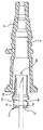
図4A〜図5Bに示される本発明の実施形態に移ると、構造の作動は、図2A〜図3Bに描かれた本発明の実施形態と類似である。この実施形態では、しかしながら、傾動板又は傾動部材40と保持ワッシャ15とが、ニードルシールドアッセンブリ5のシールド本体10と同一片の材料から一体に形成される。傾動板は好ましくはステンレス鋼等から作られる。傾動板40を保持ワッシャ15に接続する材料はスプリング45として機能し、このスプリング45は傾動板を非整列状態に付勢する。再び、作動中及び作動後、ニードルシールドアッセンブリ5に対するニードル30の近位方向の動きは、ニードル30の静止要素35と保持ワッシャ15との間の干渉により停止される。作動後、ニードルシールドアッセンブリ5に対するニードル30の遠位方向の動きは、前述されたように、傾動板40のニードルへの係合により停止される。認識されるであろうが、レッジ27は必要とされない。なぜならスプリング45と、これの保持ワッシャ15への接続とが、傾動板の底部をニードルシールドアッセンブリに対し動かないよう拘束するからである。さらに、ニードルハブとカテーテルアダプタとの相対移動を制限するため、つなぎひもが要素35の代わりに用いられても良い。
Tilting plate and spring integral with the shield Turning to the embodiment of the invention shown in FIGS. 4A-5B, the operation of the structure is similar to the embodiment of the invention depicted in FIGS. 2A-3B. In this embodiment, however, the tilting plate or tilting
相互に一体の傾動板、スプリング及び保持ワッシャ
図6A〜図7Bに示される本発明の実施形態に移ると、傾動板40、スプリング45及び保持ワッシャ15は互いに一体であるが、ニードルシールドアッセンブリ5の近位端12からは分離されている。保持ワッシャがシールド本体10に近位端において溶接、接着等により取り付けられている。描かれているように、保持ワッシャは、シールド本体の近位端の内面に取り付けられるが、保持ワッシャが外面に取り付けられても良いことが認識されるであろう。本実施形態の作動は前記実施形態と同様である。
Mutually canting plate integral, turning to the embodiment of the invention shown in the spring and retaining washer view 6A~ Figure 7B, the
摩擦部材と傾動板
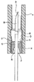
図8A〜図8C及び図9A〜図9Cを参照して、本発明のこの実施形態は部材28を使用する。部材28は、ニードル30に摩擦係合され、傾動板40を整列状態に保持すると共に、ニードルがニードルシールドアッセンブリ5に対し遠位方向に動かされたとき傾動板を非整列状態に動かす。特に、ニードルシールドアッセンブリ5は、傾動板40と、例えば弾性ワッシャである摩擦部材28とを含む。ニードル30に摩擦的に係合すると共に傾動板に接触する他の構造が採用されることもでき、このような構造も本発明の実施形態である。弾性ワッシャは好ましくはシールド本体10内にスライド可能に嵌まるように設計される。弾性ワッシャ28は、近位端36から遠位端37に伸びる中心空所29を有する。ニードル30は空所29を挿通し、ワッシャ28はニードル30に摩擦嵌合により係合される。ニードル30が弾性ワッシャ28を通って遠位方向及び近位方向に移動すると、これらの間の摩擦が弾性ワッシャ28をニードル30に連動させようとする。
Friction Member and Tilting Plate Referring to FIGS. 8A-8C and 9A-9C, this embodiment of the present invention uses
ニードルシールドアッセンブリ5のシールド本体10は、保持ワッシャ15を区画する近位部12を含む。シールド本体は遠位開口13を有し、保持ワッシャは近位開口14を有する。近位開口14は、ニードル30のシャフトの直径より僅かに大きいが、ニードル30の静止要素35の通過を許容するほどに大きくないよう設計される。保持ワッシャ15は、弾性ワッシャ28のためのストッパ(backstop)としても機能し、それを傾動板40の裏側のシールド本体内に固定する。弾性ワッシャ28がニードル30により近位方向に引き摺られると、それは最終的に保持ワッシャ15に当たり、ニードルシールドアッセンブリに対するさらなる移動を許容されない(図8B参照)。
The
傾動板40は、弾性ワッシャ28の遠位側に位置され、ニードル30によって軸方向に収容される。シールド本体10から内側に突出するのは整列アーム19である。整列アーム19は、傾動板40がその位置で遠位方向に動くのを規制する積極ストッパを形成する。シールド本体10の側壁9の対向する内面は、滑らかであり、傾動板40の起こり得る遠位方向の動きを妨げない。それ故、整列アーム19は、傾動板40が回転するポイントを規定する。本発明の他の実施形態のように、傾動板が十分大きく回転されたとき、それは、前記同様の方法でニードルシャフト30を締め付け始める。この例において、整列アーム19と弾性ワッシャ28とは、それ故、傾動板保持手段又は保持装置として機能する。
The tilting
弾性ワッシャ28は、整列アーム19と協働して、傾動板40の傾動又は作動を引き起こす。弾性ワッシャ28がニードルシャフト30に摩擦嵌合されるので、ニードルシャフト30がニードルシールドアッセンブリ5に対し遠位方向に駆動されると、弾性ワッシャ28はそれに引き摺られる。図8Cに示されるように、弾性ワッシャ28は傾動板40を押圧してそれを遠位方向に付勢する。傾動板が(保持アーム19によって)一側でのみ規制されるので、それは傾いてニードル30に巻き付く。空所128が、ワッシャ128の遠位端に形成され、ワッシャからの力を傾動板の周縁に伝え、傾動を促進する。
The
弾性ワッシャ28は様々な長さ及び形状を有することができ、このようなものも本発明の実施形態である。図8A〜Cから図9A〜Cに示されるように、ワッシャは漏刻形状を有する。ワッシャは単純な平板、ドーナツ型リング等であってもよい。ワッシャの特定の形状が、特定の用途に基づいて当業者により選択され得る。図8Aに描かれたワッシャは傾動板に取り付けられていないけれども、ワッシャが傾動板に取り付けられることができ、さらに機能し得ることが認識されるであろう。
The
保持ワッシャ15と整列アーム19との間に形成された空所48は、弾性ワッシャ28がシールド本体10内に位置するのを許容するのに適したいかなる長さであってもよい。弾性ワッシャ28の内径(即ち、ニードルシャフト30に接触する面)は、滑らかであったり、粗くされたりすることができる。それは、ニードル30に対する摩擦を調節するため、列状フィン若しくはリブ、又は任意の要素の組み合わせを有することもできる。弾性ワッシャ28は、自然な円筒状であることができ、傾動板40の全面に接触することができる。ワッシャ28は、その遠位端37で切頭状とされ、特にその最遠位部が整列アーム19のちょうど反対側の位置で傾動板40に当たるように整列されることができる。これは、ニードル30の遠位方向の動作中に傾動板40により強い力を与えるのを容易にする。
The
使用において、カテーテルアッセンブリ100のニードル先端32は、患者の静脈に挿入され、カテーテルも静脈に位置づける。その後ニードル30はカテーテル108を通じて引き抜かれる。ニードルは、弾性ワッシャ28に摩擦力を作用させ、ニードルがニードルシールドアッセンブリ5を通じて引かれる際それを近位方向に付勢する。図8A〜Cに示されるように、弾性ワッシャは、ニードルシールドアッセンブリの近位端12に隣接し、ニードルが中心空所29を通じてスライドするとき摩擦部材を停止させる。ニードルの要素35がニードルシールドアッセンブリの近位端12(例えば保持ワッシャ15)に接触したとき、要素は近位端に係合し、ニードルシールドアッセンブリに対するニードルのさらなる近位方向の移動を規制する。ニードル30がカテーテルアダプタ8からさらに引き抜かれると、図8Bに示されるように、ニードルシールドアッセンブリ5はシールドハウジング6から引き出される(「ボトミングアウト(bottoming out)」と称される)。
In use, the
ニードル30がニードルシールドアッセンブリ5に対し遠位方向に移動されると、摩擦部材28はニードル30との摩擦により遠位方向に付勢される。摩擦部材が傾動板40に係合すると、傾動板も遠位方向に付勢される。傾動板の一部に隣接する整列アーム19は、その位置を規制し、図8Cに示されるように、傾動板の非整列状態又は作動状態への傾動を生じさせる。図8C及び図9Cに描かれているように、要素35は摩擦部材に係合し、それを遠位方向に動かし、傾動板に係合させる。図11C及び図12Cに見られるように、摩擦部材はニードルによりきつく嵌合されることができる。これにより、要素が摩擦部材に係合するしないに拘らず、それがニードルと共に移動する。いずれの場合も、傾動板40が傾斜されたとき、傾動板の穴42のエッジ43はニードルの外面に巻き付き、傾動板40(ひいてはニードルシールドアッセンブリ5)に対するニードル30のさらなる移動を防止する。ニードルシールドアッセンブリのシールド本体10は、傾動板が作動されたときニードル30の先端32がニードルシールドアッセンブリの遠位端11から再出現しないのを確実にするほど十分に長い。
When the
ゴムワッシャ及びインターロックと傾動板
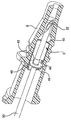
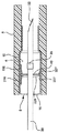
本発明の一形態のさらなる実施例が図10A〜Cに示されている。ニードル30がシールドされた位置にあるときまでカテーテルアダプタ8をシールド本体10にロックするためのインターロック50が含まれる。ニードルの静止要素35が、アダプタリリース55を作動させニードルシールドアッセンブリ5をカテーテルアダプタから離脱させるために使用される。傾動板40は、弾性ワッシャ28、レッジ27及び整列アーム227によって整列位置に維持される。レッジはニードルシールドアッセンブリ5に固定して取り付けられる。整列アームは、アダプタリリース55に取り付けられたリーフスプリングの形態であってもよい。
Rubber Washer and Interlock and Tilt Plate A further embodiment of one form of the present invention is shown in FIGS. An
図10Bに示されるように、ニードル30の静止要素35は、シールド本体又は保持ワッシャ15の近位端12にボトミングアウトする前に、リリースピン56の近位壁155に係合し、それを遠位位置57から近位位置58へと引きずる(図10Aと図10Bとを比較のこと)。ニードルシールドアッセンブリ5は複数のロッキングフランジ158を含み、ロッキングフランジ158は、ニードルシールドアッセンブリの遠位端付近に取り付けられ近位方向に伸びるリーフスプリングの形態をもつ。それらの元々の無変形状態において、フランジは比較的直線的に伸びる(即ち、ニードルシールドアッセンブリ5の軸に平行に)(図10C)。組み付けられると、ロッキングフランジ158はアダプタ8のカラー180に係合し、カラー(そしてアダプタ)がニードルシールドアッセンブリから外れるのを防止する。図10A参照。それが図10Aに示される遠位位置57にあるとき、リリースピン56はロッキングフランジ158が半径方向内側に変形するのを防止する。リリースピンが近位位置58に移動されると、それはフランジ158と非係合となり、フランジは自由に半径方向外側に曲がれるようになる。結局、カテーテルアダプタ8がニードルシールドアッセンブリに対し遠位方向に移動すると、図10Bに見られるようにカラーがロッキングフランジを半径方向外側に押し、カラーがロッキングフランジを滑って通過できるようになる。結果として、ニードルシールドアッセンブリ5はアダプタ8からすべり外せる。図面に描かれているように、ニードルシールドアッセンブリ5の遠位開口13は、ニードル先端32がシールドされた後においても開放されている。再出現をさらに防止するための横断バリアを作るため、ある長さのニードルシールドクリップ又は他のそのような機構がさらに使用されてもよいことが認識されるであろう。また、ニードルシールドアッセンブリ5がニードル30の先端32から滑り外れるのを阻止するため、静止要素35が採用されている。つなぎひも等の他の構造がそのような外れを防止するために採用されてもよいことが認識されるであろう。
As shown in FIG. 10B, the
使用において、カテーテルアッセンブリ100のニードル先端32が患者の静脈に挿入され、カテーテル108を静脈に同様に位置させる。ニードル30が、カテーテル108及びカテーテルアダプタ8を通じて引き抜かれる。ニードルはワッシャ28に摩擦力を作用させる。ワッシャは、アダプタリリース55の近位壁155によって定位置に保持される。ニードルの要素35が近位壁に係合したとき、それは壁の開口内に嵌まることができず、アダプタリリースをシールド本体10に対し近位方向に引く。アダプタリリースが近位方向に移動すると、整列アーム227が傾動板40に被さるようにそれる。整列アームは、それが遠位方向に移動されたとき傾動板を非整列状態に傾けるように、斜めの形状を有している。アダプタリリースは、近位壁155がシールド本体の近位端12に接触するまでシールド本体内で移動し続ける。この位置において、ニードルシールドアッセンブリに対するニードルの遠位方向のさらなる移動が規制される(図10B参照)。
In use, the
アダプタリリース55がその遠位位置57からその近位位置58まで移動されると、リリースピン56がロッキングフランジ158との係合から引き外される。そしてカラー180がニードルシールドアッセンブリから出るにつれ、ロッキングフランジは半径方向外側に自由に変形可能となる。このように、ニードルシールドアッセンブリ5はアダプタ8から分離され得る。
As the
ニードル30がニードルシールドアッセンブリ5に対し遠位方向に付勢されると、ワッシャ28とニードルとの間の摩擦がワッシャを同様に遠位方向に付勢する。ワッシャは傾動板40に係合し、それを遠位方向に付勢する。傾動板はレッジ27によって一端縁の位置で拘束される。結果的に、ニードルが遠位方向に移動されるにつれ、傾動板は一層傾き、ニードルに一層しっかりと巻き付き、ニードルシールドアッセンブリ5に対するニードルのさらなる移動を防止する。
As the
スプリングアーム保持と傾動板
図11A〜C及び図12A〜Cを参照して、本発明のこの実施形態は作動において図8A〜C及び図9A〜Cに描かれた実施形態と同様である。しかしながら、この実施形態では、スプリングアーム427が作動前に半径方向内側に圧縮され、使用前に傾動板40を整列状態に維持するのを助ける。図11A参照。弾性ワッシャ28と保持アーム16及びレッジ27との協働により、傾動板40は作動前に整列状態に維持される。ニードルシールドアッセンブリ5が作動される前、ニードル30はアッセンブリ内で近位方向及び遠位方向に移動されることができる。使用において、ニードルは、要素35が保持ワッシャ15に接触するまで引かれる。ニードルの更なる移動は、ニードルシールドアッセンブリ5を、アダプタ8のシールドハウジング6から引き出す。図11C参照。この位置において、スプリングアーム427は、無応力状態となるまで半径方向外側に移動する。レッジ27はそれ故傾動板40の底縁に非係合となり、それの回転を許容する。ニードルがニードルシールドアッセンブリ5に対し遠位方向に付勢されると、それはワッシャ28に作用し、それを同様に遠位方向に付勢する。ワッシャは傾動板に係合し、次いで、それを遠位方向に付勢する。傾動板の頂縁は保持アーム16によって移動できぬようにされている。結果として、傾動板はニードル30へと回転し、ニードル30に巻き付き、更なる近位方向の動きを規制する。図11C参照。
Spring Arm Holding and Tilt Plate Referring to FIGS. 11A-C and 12A-C, this embodiment of the present invention is similar in operation to the embodiment depicted in FIGS. 8A-C and 9A-C. However, in this embodiment, the
二方向シングル傾動板
図13A〜図13Cは、本発明の一形態の他の実施例を示す。これにおいては一つの傾動板40が含まれ、この傾動板40はニードル30に巻き付いて、ニードルシールドアッセンブリ5に対するニードルの近位方向及び遠位方向の両方向の移動を防止する。ニードルシールドアッセンブリは、シールド本体10に一体に形成された近位保持アーム216及び遠位保持アーム116を含む。近位レッジ227と遠位レッジ327とがスプリングアーム427に設けられる。図13Aに描かれているように、アダプタ8のシールドハウジング6は、スプリングアームを半径方向内側に圧縮し或いは曲げ、傾動板40に係合させる。弾性ワッシャ228が傾動板に取り付けられ、ニードルに摩擦的に係合される。要素35はニードルに恒久的に取り付けられている。ニードルシールドアッセンブリの遠位端の保持ワッシャ15は開口14を含み、この開口14は、ニードルの挿通を許容するが要素35の通過は阻止するようなサイズとされる。
Bidirectional Single Tilt Plate FIGS. 13A-13C illustrate another embodiment of one aspect of the present invention. In this, a
使用において、ユーザは、オーバー・ザ・ニードルカテーテルアッセンブリ10のニードル先端32を患者の静脈に挿入する。フラッシュバックの確認時、ユーザはニードルハブ110をつかみ、ニードルハブをカテーテルアダプタ8から引き離し、ニードル30をカテーテルアダプタ8及びニードルシールドアッセンブリ5を通じて引き抜く。図13A参照。ニードルは、要素35が保持ワッシャ15に当たるまでニードルシールドアッセンブリを通じて引き抜かれ続ける。ニードルの更なる移動は、ニードルシールドアッセンブリ5を、アダプタ8のシールドハウジング6から引き抜かせる。図13B参照。ニードルシールドアッセンブリがカテーテルアダプタのシールドハウジングから完全に引き抜かれると、スプリングアーム427がニードルシールドアッセンブリから半径方向外側に回転可能となる。結果的に、近位レッジ227及び遠位レッジ327は傾動板40に対し非係合となる。図13C参照。その結果、傾動板は回転されることができる。傾動板の上縁は保持アーム116,216によって遠位方向及び近位方向のいずれにも動けない。
In use, the user inserts the
デュアル傾動板
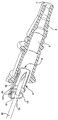
本発明の他の実施形態が図14A〜図14Cに開示されている。ニードルシールドアッセンブリ5は、好ましくはシールド本体10に一体に形成された遠位保持アーム116及び近位保持アーム216を含む。図示されるように、保持アームは、例えば曲げ(ベンディング)により、半径方向内側に変形される。遠位傾動板140と近位傾動板240とがシールド本体内に配置されている。これら傾動板は、後述されるように、保持アーム、遠位レッジ327、近位レッジ227及び弾性ワッシャ28の協働により、整列状態に維持される。レッジ227,327はスプリングアーム527に設けられる。ニードルシールドアッセンブリがアダプタ8のシールドハウジング6内に配置されるとき、スプリングアーム527は半径方向内側に付勢され、これによりレッジ227,327が傾動板140,240に係合する。摩擦部材、例えば漏刻形状のワッシャ28が、シールド本体10内で遠位傾動板140と近位傾動板240との間に配置される。弾性ワッシャ28はニードルに摩擦係合する。本発明のこの形態のある実施例において、弾性ワッシャ28は、図14Aに描かれているように、二つの傾動板の間に配置されるとき圧縮されてもよい。この場合、ワッシャは、傾動板に連続的な付勢力を作用する。この付勢力はニードルシールドアッセンブリによって受け止められる。
Dual Tilt Plate Another embodiment of the present invention is disclosed in FIGS. 14A-14C. The
使用において、オーバー・ザ・ニードルカテーテルアッセンブリ100のニードル先端32は患者の静脈に挿入される。フラッシュバックの確認時、ニードル30はカテーテル108を通じて引き抜かれ、これによりニードルはニードルシールドアッセンブリ5を挿通する。遠位傾動板140は、弾性ワッシャ28、遠位保持アーム116及び遠位レッジ327の協働により、ニードルと整列状態に維持される。近位傾動板240は、弾性ワッシャ、近位保持アーム216及び近位レッジ227の協働により、ワッシャ28(これはニードルに倣おうとし、それ故、傾動板に逆らって移動される)の付勢に拘わらず、整列状態に維持される。傾動板がニードルに整列されるので、ニードルは傾動板の開口を自由に通過できる。ニードルがさらに引かれると、要素35は保持ワッシャ15に係合し、ニードルシールドアッセンブリ5をアダプタ8のシールドハウジング6から引き出す。図14B参照。ニードルシールドアッセンブリのカテーテルアダプタからの取り外し時、スプリングアーム527はシールド本体から半径方向外側に拡径可能となり、これにより近位レッジ227が近位傾動板240に非係合となり、遠位レッジ327が遠位傾動板140に非係合となる。この非係合は傾動板の回転を許容する。仮にワッシャが圧縮されていると、それは膨張可能となり、それゆえ傾動板の即時の傾動を生じさせる。ニードル30がニードルシールドアッセンブリ5に対し近位方向に付勢されると、ニードルはワッシャ28を遠位方向に付勢し、これは、図14Bに見られるように、近位傾動板240を回転させる。ニードルがニードルシールドアッセンブリに対し遠位方向に付勢されると、ワッシャ28は遠位方向に動き、遠位傾動板140を遠位方向に動かすよう付勢する。遠位保持アーム116は、遠位傾動板140がニードルシールド本体10内で遠位方向に動くのを妨げ、遠位傾動板の傾動とニードルへの巻き付きとをもたらす。図14C参照。
In use, the
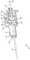
つなぎひもとデュアル傾動板
図15A〜図15Cを参照すると、本発明の実施形態が描かれており、これは、ニードルシールドアッセンブリ5を、カテーテルアダプタ8のシールドハウジング6から引き出すためのつなぎひも(つなぎ縄、テザー;tether)400を用いている。つなぎひもは、ニードルハブ110と、ニードルシールドアッセンブリの近位端12とに取り付けられている。図15A〜図15Cに描かれているように、つなぎひもは保持ワッシャ15に取り付けられている。つなぎひもがニードルシールドアッセンブリをカテーテルアダプタから引き出すので、ニードルの要素35は必要とされない。使用において、ニードル先端32が患者の静脈に挿入され、カテーテル108の先端を同様に静脈に届ける。そして介護者は、カテーテルアダプタ8を定位置に保持しながら、ニードルハブ110を引く。図15B参照。ニードルハブが近位方向に移動されると、ニードルシールドアッセンブリ5は、カテーテルアダプタ8のシールドハウジング6から引き出される。図15B参照。この実施形態のその他の作動は、図14A〜図14Cに関連して図説された実施形態と同様である。
Tie and Dual Tilt Plate Referring to FIGS. 15A-15C, an embodiment of the present invention is depicted, which is a tether for pulling the
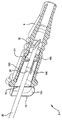
シングル傾動板とつなぎひも
ここで図16A〜図16Dを参照すると、図13A〜図13Cに描かれた実施形態に類似の本発明の実施形態が描かれている。しかしながら、ニードルシールドアッセンブリ5を、カテーテルアダプタ8のシールドハウジング6から引き出すため、つなぎひも400が用いられている。結果的に、ニードルの要素35は必要とされない。一つの傾動板40が作動後にニードル30に巻き付き、ニードルシールドアッセンブリに対するニードルの近位方向及び遠位方向の両方向の移動を妨げる。ニードルシールドアッセンブリ5は、シールド本体10に一体に形成された近位保持アーム216と遠位保持アーム116とを含む。近位レッジ227及び遠位レッジ327がスプリングアーム427に設けられる。図16Aに描かれているように、アダプタ8のシールドハウジング6は、スプリングアームを半径方向内側に圧縮し或いは曲げ、傾動板40に係合させる。弾性ワッシャ228が傾動板に取り付けられ、ニードルに摩擦的に係合される。要素35はニードルに恒久的に取り付けられている。
使用において、ユーザは、オーバー・ザ・ニードルカテーテル100のニードル先端32を患者の静脈に挿入し、カテーテル108の先端を同様に静脈に位置付ける。フラッシュバックの確認時、ユーザはニードルハブ110をつかみ、ニードルハブをカテーテルアダプタ8から引き離し、ニードル30をカテーテルアダプタ8及びニードルシールドアッセンブリ5を通じて引き抜く。図16B参照。つなぎひも400がその全長まで伸ばされたとき、ニードルハブの更なる近位方向の移動が始まり、ニードルシールドアッセンブリをカテーテルアダプタから引き抜く。図16B参照。ニードルシールドアッセンブリがカテーテルアダプタのシールドハウジングから完全に引き抜かれると、スプリングアーム427がニードルシールドアッセンブリから半径方向外側に回転可能となる。結果的に、近位レッジ227及び遠位レッジ327は傾動板40に対し非係合となる。図16C参照。その結果、傾動板は回転されることができる。傾動板の上縁は保持アーム116,216によって遠位方向及び近位方向のいずれにも動けない。図13A〜Cに関連して説明されたように、ニードルの再出現は、傾動板からニードル30の外壁への巻き付き力によって防止される。図16D参照。
Single Tilt Plate and Tethers Referring now to FIGS. 16A-16D, an embodiment of the present invention is depicted that is similar to the embodiment depicted in FIGS. 13A-13C. However, a
In use, the user inserts the
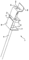
傾動スロットとクリップ
図17A〜図17Dを参照すると、本発明の実施形態が描かれており、これにおいてはクリップ130が、ニードルシールドアッセンブリ5のハウジング内に配置されている。クリップは、実質的にV字状の部材であり、ハウジングに固定して設けられた第1の脚131を備えている。第2の脚132が第1の脚に曲がりヒンジ133を介して設けられている。スライドタブ134が第2の脚に形成され、作動中にニードル30と第2の脚との間の抵抗を減じると共に、ニードル30にスライド係合する。図17A及び図17Bに示されるように、作動前、クリップ130は圧縮され、クリップに整列された位置におけるニードルシールド5内のニードルの存在により、圧縮状態に維持される。トラップアーム730が、第2の脚に取り付けられ、カテーテルアダプタ(図示せず)に係合し、それのニードルシールドアッセンブリからの取り外しを妨げる。ニードルが引かれると、それは第2の脚への係合を終え、これにより曲がりヒンジ133が急速に開く。図17C及び図17D参照。そしてトラップアームがカテーテルアダプタとの係合から離脱し、これによりそれがニードルシールドアッセンブリから取り外され得るようになる。
Tilt Slot and Clip Referring to FIGS. 17A-17D, an embodiment of the present invention is depicted in which a
ガイドプレート140が、クリップ130の第2の脚132に取り付けられる。ガイドプレート140はガイドスロット141を含む。傾動ピン142が傾動板40に取り付けられる。傾動ピンは傾動板に一体に形成されても良い。傾動ピンはガイドスロット141の中に配置されている。図17Aに示されるように、非作動状態において、傾動スロット内の傾動ピンの位置は、傾動板をニードル30と整列された状態に維持する。結果として、ニードルは傾動板の開口を通じて抵抗無く引き抜かれ得る。ニードルがクリップを超えて引き抜かれると、クリップは急速に開き、ガイドプレートをそれに従って移動させる。図17C及び図17D参照。ガイドプレートの移動は、ピン142を遠位方向に移動させることになる。傾動板の底縁はその近位方向又は遠位方向の移動が妨げられる。なぜならそれは、ニードルシールドアッセンブリハウジングの溝740内に保持されているからである。ピン142が遠位方向に移動されると、傾動板が回転されてニードルに巻き付き係合する。ニードルがニードルシールドアッセンブリに対し遠位方向に付勢されると、傾動板の係合は、ニードルがニードルシールドアッセンブリから再出現するのを妨げる。保持ワッシャ15は、ニードルシールドアッセンブリの近位端からの要素35の脱出(さらにはニードル先端32の脱出)を妨げる。ニードルシールドアッセンブリがニードルの先端から滑り外れるのを防止するため、要素が取り除かれつなぎひもが設けられてもよいことが認識されるであろう。
A
一体化されたワッシャとフローティングプレート
ここで図18A〜図18Dを参照すると、本発明の実施形態が描かれており、これは、アクチュエータアーム(作動アーム)150に一体的に形成された保持ワッシャ15を含む。開口14が保持ワッシャに配置される。ニードルの通過を容易にし、保持ワッシャとニードルとの間の相対的に垂直な整列を保証するため、リップが開口14の周囲に形成されてもよい。アクチュエータアームは、前壁151とスライドプレート152とを含む。穴153が、前壁に配置されているが、ある実施においては省略されることもできる。傾動板40は、一対のU字状スリーブ154により、ニードル周辺の定位置に維持される。スリーブは、傾動板40に比較的接近して嵌まるが、傾動板がスリーブ内でスライドできないほどには接近されない。図18B及び図18Dを比較のこと。U字状スリーブはそれ自身アーム150に取り付けられている。穴155が、傾動板の直上でアームに配置されている。
Integrated Washer and Floating Plate Referring now to FIGS. 18A-18D, an embodiment of the present invention is depicted, which includes a holding
図18A及び図18Bに見られるように、非作動状態において、保持プレート15とアーム150とは、保持ワッシャの開口14内におけるニードル30の存在及びニードルのプレート152との係合により、互いから離れるように曲げられ(即ち、開方向に付勢され)、この曲げられた状態に維持される。患者の静脈へのカテーテル108の挿入後、ニードルシールドアッセンブリ5はニードル先端32に向けて移動される(或いは、その代わりに、ニードル30がニードルシールドアッセンブリを通じて引き抜かれる)。ニードルがニードルシールドアッセンブリ5に対し近位方向に移動すると、ニードルの先端32はスライドプレート152を通過し、これにより、図18C及び図18Dに見られるように、アーム150と保持プレート15とがそれらの無付勢状態に復元可能となり、互いに向かって回転する。この無付勢状態又は作動状態において、U字状部材154は保持ワッシャ15に対して移動する(特に、U字状部材は保持プレートに対し回転される)。図18B及び図18Dを比較のこと。こうして、傾動板40も保持ワッシャ(よってニードル)に対し移動される。効果的に、傾動板はニードルに対し傾けられ、ニードルの外面に係合するようになる。作動状態において、傾動板の頂部はアーム150の穴155を通過して突出する。認識されるであろうが、アーム150はそのような穴155が必要とされないように設計されることができるが、これはより大きなニードルシールドアッセンブリ5に帰する。
As seen in FIGS. 18A and 18B, in a non-actuated state, the retaining
一体化された板と係合フック
ここで図19A及び図19Bを参照すると、本発明の実施形態が描かれており、これは、図4A,Bに描かれた実施形態にやや類似しており、ニードル先端32がニードルシールドアッセンブリ5内に引き抜かれるまでカテーテルアダプタ8に係合する機構を含む。ニードルシールドアッセンブリは、二つの係合アーム190(好ましくはシールド本体10に一体的に形成されたリーフスプリングの形態である)を含み、これらはニードルシールドアッセンブリの本体から半径方向外側に付勢される。複数のフック191が係合アーム190の遠位端に取り付けられる。非作動状態において、ニードル30はフックの間に位置され、これによりフックと係合アームとを半径方向外側に付勢する。フックはそれゆえカテーテルアダプタ8の環状溝192内に配置される。結果的に、カテーテルアダプタはニードルシールドアッセンブリから移動され得ない。ニードルがフックの間から引き抜かれると、図19Bに見られるように係合アームは半径方向内側に曲がり、それらの無応力状態となる。こうしてフック191は環状溝192から離脱する。結果的に、ニードルシールドアッセンブリ5がカテーテルアダプタ8から取り外されることができるようになる。
Integrated Plate and Engagement Hook Referring now to FIGS. 19A and 19B, an embodiment of the present invention is depicted, which is somewhat similar to the embodiment depicted in FIGS. 4A and B. A mechanism for engaging the
ニードルシールドアッセンブリ5は保持ワッシャ15も含む。保持ワッシャ15は、傾動板40と一体に形成され、曲がりヒンジ部材193によって接続される。ヒンジ部材は、傾動板40を傾斜状態に付勢するスプリングである。組立時及び作動前(図19A参照)、傾動板は、曲がりヒンジ193によって作用される力と、カテーテルアダプタ8の近位端との干渉との協働によって、ニードルに整列された状態に維持される。結果的に、ニードルは抵抗無く傾動板を挿通可能となる。ニードルシールドアッセンブリがカテーテルアダプタから解放され、カテーテルアダプタから近位方向に移動すると、傾動板は曲がりヒンジ193の付勢に屈し得るようになり、ニードルの外面に係合する(図19B参照)。
一体化されたワッシャ、ヒンジ、傾動板及び作動アーム
ここで図20A及び図20Bを参照すると、本発明の実施形態が描かれており、これは、曲がりヒンジ193と一体に形成された保持ワッシャ15を含む。曲がりヒンジ193は傾動板40と一体に形成され、傾動板40は作動アーム150と一体に形成される。保持ワッシャはシールド本体10の近位端に取り付けられている。非作動状態において、傾動板は、曲がりヒンジ193によって作用される力と、作動アーム150によって作用される拘束力との協働によって、ニードル30に整列された状態に維持される。特に、曲がりヒンジ193は、傾動板を傾斜又は係合状態に付勢するスプリングとして機能する。傾動板のこの動作は、それ自身ニードルに係合される作動アームによって防止される。図20A参照。ニードル先端32が引き抜かれると、作動アーム150は、ニードル先端との係合から外れ、シールド本体10内で可動になる。結果的に、傾動板40は、曲がりヒンジ193によって作用される付勢に屈する。傾動板がニードルとの整列状態から傾斜されると、それはニードルの外面に巻き付いて係合する。切欠き159が作動アームに設けられてもよく、これは、ニードル先端の通過後、作動アームがニードルから干渉されずに動くことを許容する。
Integrated washer, hinge, tilt plate and actuating arm Referring now to Figures 20A and 20B, an embodiment of the present invention is depicted, which is integrally formed with a
前述の如く、本発明のある実施形態は、ニードル30の要素35を採用し、これによりニードルの先端32に対するニードルシールドアッセンブリ5の動作を制限する。他の実施形態はつなぎひも400を採用し、これによりニードルシールドアッセンブリに対するニードル先端の動作を制限する。認識されるであろうが、様々な実施形態において、要素はつなぎひもに置換されることができ(又はつなぎひもは要素に置換されることができ)、このようなものも本発明の実施形態である。さらに、摩擦部材は、ある実施形態においては、弾性ワッシャと称されている。認識されるであろうが、摩擦部材は、エラストマー又は、異なる特性及び様々な形状を有する他の材料から作られることができ、このようなものも本発明の実施形態である。
As previously mentioned, certain embodiments of the present invention employ the
以上の説明は、本質において、限定的というよりもむしろ例示的である。本発明の範囲及び思想から必ずしも外れない、開示例に対する応用及び変形が、当業者にとって明らかになるかもしれない。例えば、本発明の実施形態は、麻酔針、注射器、血液サンプル採集器等の他のニードルと共に使用されることができる。本発明に与えられる法的保護の範囲は、特許請求の範囲を検討することによってのみ決定され得る。 The above description is exemplary rather than limiting in nature. Applications and variations to the disclosed examples may become apparent to those skilled in the art that do not necessarily depart from the scope and spirit of the invention. For example, embodiments of the present invention can be used with other needles such as anesthesia needles, syringes, blood sample collectors and the like. The scope of legal protection afforded this invention can only be determined by studying the claims.
好適実施形態が図面に示され、これにおいて同様の符号は同様の要素を意味する。
5 ニードルシールドアッセンブリ
6 シールドハウジング
8 カテーテルアダプタ
9 側壁
10 シールド本体
11 遠位端
12 近位端
13 遠位開口
14 近位開口
15 保持ワッシャ
16 保持アーム
19 整列アーム
27 レッジ
28 部材(摩擦部材、弾性ワッシャ)
29 中心空所
30 ニードル
32 先端
35 静止要素
40 傾動板
42 穴
43 エッジ
45 スプリング
50 インターロック
55 アダプタリリース
56 リリースピン
100 カテーテルアッセンブリ
108 カテーテル
110 ニードルハブ
116 遠位保持アーム
127 リップ
130 クリップ
140 ガイドプレート
140 遠位傾動板
141 ガイドスロット
150 作動アーム
158 ロッキングフランジ
159 切欠き
190 係合アーム
191 フック
216 近位保持アーム
227 近位レッジ
227 整列アーム
228 弾性ワッシャ
240 近位傾動板
327 遠位レッジ
400 つなぎひも
427 スプリングアーム
527 スプリングアーム
DESCRIPTION OF
29
Claims (16)
直径及び遠位端を有し、前記アダプタ内にスライド可能に配置されるニードルと、
該ニードルにスライド可能に取り付けられ、前記アダプタに対して移動可能であり、前記ニードルが通過される開放遠位端と開放近位端とを有するニードルシールドアッセンブリと、
該ニードルシールドアッセンブリ内に配置され、前記ニードルの通過のための穴を有し、非作動第1位置と、ニードルの動きを制限する作動第2位置とを有する傾動板と、
該傾動板を保持するための手段であって、前記傾動板に接続し、前記ニードルの近位方向の動きに反応する手段とを備え、
前記ニードル先端が前記ニードルシールドアッセンブリ内に収容されたとき、前記傾動板保持手段が作動されて前記傾動板の前記非作動第1位置から前記作動第2位置への移動を許容し、前記保持手段が保持ワッシャを備え、前記保持ワッシャが前記ニードルのための近位開口を有し、
前記ニードルが、前記保持ワッシャの前記開口を通過できない静止要素を備え、これにより、前記ニードルが近位方向に引かれたとき、前記ニードルが前記ニードルシールドアッセンブリを引き、これにより前記ニードルシールドアッセンブリが前記アダプタのシールドハウジングから抜かれ、
前記傾動板保持手段が、前記傾動板を前記作動第2位置に付勢するスプリングと、保持アームとを備え、前記ニードルシールドアッセンブリが前記アダプタから引き抜かれたとき、前記保持アームがその自然のバイアスにより係合位置から非係合位置へと移動し、前記係合位置において前記保持アームが前記傾動板を前記非作動第1位置に保持し、前記非係合位置において前記保持アームが前記傾動板を前記作動第2位置へと解放する
オーバー・ザ・ニードルカテーテルアッセンブリ。 An adapter having a shield housing ;
A needle having a diameter and a distal end and slidably disposed within the adapter;
A needle shield assembly slidably attached to the needle, movable relative to the adapter, and having an open distal end and an open proximal end through which the needle is passed;
A canting plate disposed within the needle shield assembly, having a hole for passage of the needle, and having a non-actuated first position and an actuating second position for restricting needle movement;
Means for holding the canting plate, comprising means for connecting to the canting plate and responding to proximal movement of the needle,
When the tip of the needle is accommodated in the needle shield assembly, the tilting plate holding means is actuated to allow the tilting plate to move from the non-operating first position to the operating second position, and the holding means Comprises a retaining washer, the retaining washer having a proximal opening for the needle,
The needle includes a stationary element that cannot pass through the opening of the retaining washer so that when the needle is pulled proximally, the needle pulls the needle shield assembly, thereby causing the needle shield assembly to move. Unplugged from the shield housing of the adapter,
The tilting plate holding means includes a spring for biasing the tilting plate to the second operating position, and a holding arm, and when the needle shield assembly is pulled out from the adapter, the holding arm has its natural bias. Is moved from the engagement position to the non-engagement position, and in the engagement position, the holding arm holds the tilting plate in the non-operating first position, and in the non-engagement position, the holding arm moves to the tilting plate. An over-the-needle catheter assembly that releases the valve to the activated second position .
請求項1記載のニードルシールドアッセンブリ。 The needle shield assembly according to claim 1.
請求項1記載のニードルシールドアッセンブリ。 The needle shield assembly according to claim 1.
請求項1記載のニードルシールドアッセンブリ。 The needle shield assembly according to claim 1.
請求項1記載のニードルシールドアッセンブリ。 The needle shield assembly according to claim 1.
請求項1記載のニードルシールドアッセンブリ。 The needle shield assembly according to claim 1.
請求項1記載のニードルシールドアッセンブリ。 The needle shield assembly according to claim 1.
ハウジングと、 A housing;
該ハウジング内に配置されたニードルシールドアッセンブリと A needle shield assembly disposed within the housing;
を備え、 With
該ニードルシールドアッセンブリが、 The needle shield assembly is
側壁、近位端及び遠位端を有するシールド本体と、 A shield body having a side wall, a proximal end and a distal end;
整列状態から非整列状態への移動のために前記シールド本体内に配置された傾動部材と、 A tilting member disposed within the shield body for movement from an aligned state to an unaligned state;
前記シールド本体及び前記傾動部材に作動可能に係合され、前記傾動部材を前記非整列状態に付勢するスプリングと、 A spring operatively engaged with the shield body and the tilting member and biasing the tilting member into the non-aligned state;
前記シールド本体に係合され、前記傾動部材に係合する係合位置から前記傾動部材から離脱する非係合位置に付勢されて変位可能なアームと An arm that is engaged with the shield body and is biased from an engagement position that engages with the tilting member to a non-engagement position that disengages from the tilting member;
をさらに備え、 Further comprising
前記ニードルシールドアッセンブリが前記ハウジング内にあるとき、前記ハウジングが前記アームを前記係合位置に変位させ、このとき前記アームが前記傾動部材に係合し、前記傾動部材を前記整列状態に維持し、 When the needle shield assembly is in the housing, the housing displaces the arm to the engagement position, wherein the arm engages the tilt member and maintains the tilt member in the aligned state;
前記ニードルが近位方向に移動されて前記ニードルシールドアッセンブリが前記ハウジング外に引き出されたとき、前記アームが前記非係合位置に移動し、このとき前記アームが前記傾動部材から離脱し、前記傾動部材が前記非整列状態に変位される When the needle is moved in the proximal direction and the needle shield assembly is pulled out of the housing, the arm moves to the disengaged position. At this time, the arm is detached from the tilting member, and the tilting is performed. The member is displaced to the non-aligned state
装置。 apparatus.
請求項8記載の装置。 The apparatus of claim 8.
請求項9記載の装置。 The apparatus of claim 9.
請求項8記載の装置。 The apparatus of claim 8.
請求項8記載の装置。 The apparatus of claim 8.
請求項12記載の装置。 The apparatus of claim 12.
請求項8記載の装置。 The apparatus of claim 8.
請求項14記載の装置。 The apparatus of claim 14.
請求項15記載の装置。 The apparatus of claim 15.
Applications Claiming Priority (3)
| Application Number | Priority Date | Filing Date | Title |
|---|---|---|---|
| US39049902P | 2002-06-20 | 2002-06-20 | |
| US10/320,960 US6652490B2 (en) | 1998-04-09 | 2002-12-17 | Catheter and introducer needle assembly with compact needle shield |
| PCT/US2003/019670 WO2004000408A1 (en) | 2002-06-20 | 2003-06-20 | Catheter and introducer needle assembly with needle shield |
Related Child Applications (2)
| Application Number | Title | Priority Date | Filing Date |
|---|---|---|---|
| JP2009269009A Division JP5121808B2 (en) | 2002-06-20 | 2009-11-26 | Catheter and introducer needle assembly with needle shield |
| JP2009269010A Division JP5112412B2 (en) | 2002-06-20 | 2009-11-26 | Catheter and introducer needle assembly with needle shield |
Publications (2)
| Publication Number | Publication Date |
|---|---|
| JP2005529717A JP2005529717A (en) | 2005-10-06 |
| JP4457004B2 true JP4457004B2 (en) | 2010-04-28 |
Family
ID=41573530
Family Applications (3)
| Application Number | Title | Priority Date | Filing Date |
|---|---|---|---|
| JP2004516098A Expired - Lifetime JP4457004B2 (en) | 2002-06-20 | 2003-06-20 | Catheter and introducer needle assembly with needle shield |
| JP2009269009A Expired - Lifetime JP5121808B2 (en) | 2002-06-20 | 2009-11-26 | Catheter and introducer needle assembly with needle shield |
| JP2009269010A Expired - Lifetime JP5112412B2 (en) | 2002-06-20 | 2009-11-26 | Catheter and introducer needle assembly with needle shield |
Family Applications After (2)
| Application Number | Title | Priority Date | Filing Date |
|---|---|---|---|
| JP2009269009A Expired - Lifetime JP5121808B2 (en) | 2002-06-20 | 2009-11-26 | Catheter and introducer needle assembly with needle shield |
| JP2009269010A Expired - Lifetime JP5112412B2 (en) | 2002-06-20 | 2009-11-26 | Catheter and introducer needle assembly with needle shield |
Country Status (10)
| Country | Link |
|---|---|
| US (1) | US7935080B2 (en) |
| EP (9) | EP3159032B1 (en) |
| JP (3) | JP4457004B2 (en) |
| CN (2) | CN101628144B (en) |
| AT (5) | ATE544488T1 (en) |
| AU (1) | AU2003243717A1 (en) |
| BR (1) | BR0311937B1 (en) |
| DE (1) | DE60332019D1 (en) |
| ES (12) | ES2382347T3 (en) |
| WO (1) | WO2004000408A1 (en) |
Families Citing this family (133)
| Publication number | Priority date | Publication date | Assignee | Title |
|---|---|---|---|---|
| US7413562B2 (en) * | 2001-03-15 | 2008-08-19 | Specialized Health Products, Inc. | Safety shield for medical needles |
| US8066678B2 (en) * | 2001-12-17 | 2011-11-29 | Bard Access Systems, Inc. | Safety needle with collapsible sheath |
| EP1725282A1 (en) * | 2004-02-13 | 2006-11-29 | Smiths Medical ASD, Inc. | Needle tip protector |
| US7513888B2 (en) * | 2004-02-17 | 2009-04-07 | Smiths Medical Asd, Inc. | Needle guards |
| US7776016B1 (en) | 2004-02-26 | 2010-08-17 | C. R. Bard, Inc. | Huber needle safety enclosure |
| US7651476B2 (en) * | 2004-09-28 | 2010-01-26 | B. Braun Medical Inc. | Protective clips |
| US7850650B2 (en) | 2005-07-11 | 2010-12-14 | Covidien Ag | Needle safety shield with reset |
| US7828773B2 (en) | 2005-07-11 | 2010-11-09 | Covidien Ag | Safety reset key and needle assembly |
| US7905857B2 (en) | 2005-07-11 | 2011-03-15 | Covidien Ag | Needle assembly including obturator with safety reset |
| EP2497523B1 (en) * | 2005-03-07 | 2016-11-16 | Erskine Medical LLC | Catheter introducer with needle shield |
| US20060276747A1 (en) | 2005-06-06 | 2006-12-07 | Sherwood Services Ag | Needle assembly with removable depth stop |
| ATE424879T1 (en) | 2005-07-06 | 2009-03-15 | Vascular Pathways Inc | INTRAVENOUS CATHETER INSERTION DEVICE AND METHOD OF USE |
| US7731692B2 (en) | 2005-07-11 | 2010-06-08 | Covidien Ag | Device for shielding a sharp tip of a cannula and method of using the same |
| US8251950B2 (en) | 2005-08-08 | 2012-08-28 | Smiths Medical Asd, Inc. | Needle guard clip with heel |
| US7597681B2 (en) * | 2005-08-08 | 2009-10-06 | Smiths Medical Asd, Inc. | Needle guard mechanism with shroud |
| US7753877B2 (en) | 2005-08-08 | 2010-07-13 | Smiths Medical Asd, Inc. | Needle guard strut wall clip |
| US8403886B2 (en) | 2005-08-08 | 2013-03-26 | Smiths Medical Asd, Inc. | Needle guard clip with lip |
| US7632243B2 (en) | 2005-08-08 | 2009-12-15 | Smiths Medical Asd, Inc. | Duckbill catheter release mechanism |
| US8162881B2 (en) * | 2005-08-08 | 2012-04-24 | Smiths Medical Asd, Inc. | Needle guard mechanism with angled strut wall |
| US7654735B2 (en) | 2005-11-03 | 2010-02-02 | Covidien Ag | Electronic thermometer |
| US7658725B2 (en) | 2006-02-16 | 2010-02-09 | Smiths Medical Asd, Inc. | Enclosed needle device with duckbill release mechanism |
| US20080097330A1 (en) * | 2006-07-18 | 2008-04-24 | Smiths Medical Asd, Inc. | Catheter insertion device with fluid leakage control |
| CN101112639B (en) * | 2006-07-27 | 2012-07-18 | 贝克顿·迪金森公司 | Vessel having a safeguard device and introducing needle component |
| CN101112638B (en) * | 2006-07-27 | 2011-06-08 | 贝克顿·迪金森公司 | Vessel having a safeguard device and introducing needle component |
| US8382718B2 (en) * | 2006-07-31 | 2013-02-26 | B. Braun Melsungen Ag | Needle assembly and components thereof |
| JP4994775B2 (en) | 2006-10-12 | 2012-08-08 | 日本コヴィディエン株式会社 | Needle point protector |
| US7871397B2 (en) * | 2006-12-26 | 2011-01-18 | Stat Medical Devices, Inc. | Pen needle tip |
| US10085680B2 (en) * | 2007-03-07 | 2018-10-02 | Becton, Dickinson And Company | Safety blood collection assembly with indicator |
| US8597253B2 (en) | 2007-04-20 | 2013-12-03 | Bard Access Systems | Huber needle with safety sheath |
| DE602008003791D1 (en) | 2007-05-07 | 2011-01-13 | Vascular Pathways Inc | INTRODUCTION OF INTRAVENOUS CATHETER AND BLOOD DETECTING DEVICE AND METHOD OF USE |
| US8357104B2 (en) | 2007-11-01 | 2013-01-22 | Coviden Lp | Active stylet safety shield |
| ES2788079T3 (en) * | 2007-11-21 | 2020-10-20 | Becton Dickinson Co | Needle safety device |
| US8858503B2 (en) * | 2007-12-21 | 2014-10-14 | Becton, Dickinson And Company | Tip shield with gripping surfaces and guard features |
| EP2077133A1 (en) | 2008-01-03 | 2009-07-08 | Eastern Medikit Ltd. | Safety I.V. catheter with tip locking insert |
| EP2161049A1 (en) * | 2008-09-05 | 2010-03-10 | Eastern Medikit Ltd. | Safety IV catheter with tip protective housing |
| EP2168627A1 (en) * | 2008-09-11 | 2010-03-31 | Eastern Medikit Ltd. | Safety I.V. catheter with cylindrical tip protector |
| US8231582B2 (en) | 2008-12-11 | 2012-07-31 | Bard Access Systems, Inc. | Device for removing a Huber needle from a patient |
| US8496623B2 (en) * | 2009-03-02 | 2013-07-30 | Becton, Dickinson And Company | Bi-directional cannula feature capture mechanism |
| US8439877B2 (en) * | 2009-03-02 | 2013-05-14 | Becton, Dickinson And Company | Bi-directionally engageable cannula crimp feature |
| US9399120B2 (en) | 2009-03-02 | 2016-07-26 | Becton, Dickinson And Company | Bi-directional cannula feature capture mechanism |
| US8936575B2 (en) † | 2009-03-19 | 2015-01-20 | Becton, Dickinson And Company | Cannula-tip shielding mechanism |
| US20110023281A1 (en) * | 2009-04-30 | 2011-02-03 | Stat Medical Devices, Inc. | Pen injection device cap with integral pen needle quick release and/or removal system |
| DE102009020061A1 (en) * | 2009-05-06 | 2010-11-11 | B. Braun Melsungen Ag | Needle protection device for a medical hollow needle |
| US9700681B2 (en) * | 2009-05-15 | 2017-07-11 | Stat Medical Devices, Inc. | Pen needle with quick release and/or removal system |
| US20100305519A1 (en) * | 2009-06-02 | 2010-12-02 | Becton, Dickinson And Company | Cannula having an overlapping cannula feature and notch feature |
| US8474300B2 (en) * | 2009-07-20 | 2013-07-02 | Becton, Dickinson And Company | Methods to provide a feature on a needle |
| SE534021C2 (en) | 2009-08-13 | 2011-04-05 | Vigmed Ab | Protective device for a catheter needle tip |
| US20110060292A1 (en) * | 2009-08-14 | 2011-03-10 | Stat Medical Devices, Inc. | Pen needle storage device with integral removal and/or installation system |
| SE535169C2 (en) * | 2010-04-13 | 2012-05-08 | Vigmed Ab | Polymer protective device for a catheter needle tip |
| US10384039B2 (en) | 2010-05-14 | 2019-08-20 | C. R. Bard, Inc. | Catheter insertion device including top-mounted advancement components |
| US9872971B2 (en) | 2010-05-14 | 2018-01-23 | C. R. Bard, Inc. | Guidewire extension system for a catheter placement device |
| US8932258B2 (en) | 2010-05-14 | 2015-01-13 | C. R. Bard, Inc. | Catheter placement device and method |
| US11925779B2 (en) | 2010-05-14 | 2024-03-12 | C. R. Bard, Inc. | Catheter insertion device including top-mounted advancement components |
| US9950139B2 (en) | 2010-05-14 | 2018-04-24 | C. R. Bard, Inc. | Catheter placement device including guidewire and catheter control elements |
| US8257322B2 (en) | 2010-06-02 | 2012-09-04 | Smiths Medical Asd, Inc. | Tip protector for a safety catheter |
| CN102284110A (en) * | 2010-06-18 | 2011-12-21 | 苏州康益明华生物医药科技有限公司 | Sheath-type safety needle guard |
| CN102284109A (en) * | 2010-06-18 | 2011-12-21 | 苏州康益明华生物医药科技有限公司 | Receiving type safe needle protector with sheath |
| FR2961701B1 (en) * | 2010-06-28 | 2014-06-20 | Braun Medical Sas | NEEDLE FOR INJECTING OR EXTRACTING FLUIDS WITH A SAFETY DEVICE FOR PROTECTING AGAINST INJURIES ON THE NEEDLE'S NEEDLE |
| CA2806393A1 (en) | 2010-09-10 | 2012-03-15 | C.R. Bard, Inc. | Systems for isolation of a needle-based infusion set |
| US10525234B2 (en) | 2010-09-10 | 2020-01-07 | C. R. Bard, Inc. | Antimicrobial/haemostatic interface pad for placement between percutaneously placed medical device and patient skin |
| US20140066894A1 (en) | 2010-09-10 | 2014-03-06 | C. R. Bard, Inc. | Self-Sealing Pad for a Needle-Based Infusion Set |
| WO2012039672A1 (en) | 2010-09-23 | 2012-03-29 | Vigmed Ab | Needle tip shielding device |
| US9428254B1 (en) | 2010-09-24 | 2016-08-30 | Katalyst Surgical, Llc | Microsurgical handle and instrument |
| US10463803B2 (en) | 2010-11-12 | 2019-11-05 | Stat Medical Devices, Inc. | Pen needle with quick release and/or removal system |
| EP2646091A4 (en) | 2010-12-02 | 2015-12-23 | Erskine Medical Llc | Needle shield assembly with hub engagement member for needle device |
| ES2725777T3 (en) | 2010-12-02 | 2019-09-27 | Erskine Medical Llc | Release mechanism for use with needle protection devices |
| US8690833B2 (en) | 2011-01-31 | 2014-04-08 | Vascular Pathways, Inc. | Intravenous catheter and insertion device with reduced blood spatter |
| US8961470B2 (en) | 2011-02-17 | 2015-02-24 | Steven Schraga | Pen needle with safety shield system |
| EP3563898B1 (en) | 2011-02-25 | 2020-11-11 | C.R. Bard, Inc. | Medical component insertion device including a retractable needle |
| US9238104B2 (en) | 2011-02-28 | 2016-01-19 | Injectimed, Inc. | Needle guard |
| US8764711B2 (en) | 2011-02-28 | 2014-07-01 | Injectimed, Inc. | Needle guard |
| CN103608060B (en) | 2011-04-07 | 2016-01-27 | 厄斯金医学有限公司 | Needle shield |
| US8486024B2 (en) | 2011-04-27 | 2013-07-16 | Covidien Lp | Safety IV catheter assemblies |
| USD903101S1 (en) | 2011-05-13 | 2020-11-24 | C. R. Bard, Inc. | Catheter |
| EP2760520A1 (en) | 2011-09-26 | 2014-08-06 | Covidien LP | Safety catheter |
| WO2013048768A1 (en) | 2011-09-26 | 2013-04-04 | Covidien Lp | Safety iv catheter and needle assembly |
| US8834422B2 (en) | 2011-10-14 | 2014-09-16 | Covidien Lp | Vascular access assembly and safety device |
| CA3012939C (en) | 2011-12-07 | 2020-07-21 | Becton, Dickinson And Company | Needle shielding assemblies and infusion devices for use therewith |
| US9078978B2 (en) | 2011-12-28 | 2015-07-14 | Stat Medical Devices, Inc. | Needle assembly with safety system for a syringe or fluid sampling device and method of making and using the same |
| US9468423B2 (en) * | 2012-01-10 | 2016-10-18 | Becton, Dickinson And Company | Safety shield for fluid specimen container |
| US9138346B2 (en) | 2012-01-26 | 2015-09-22 | Katalyst Surgical, Llc | Surgical instrument sleeve |
| SE537334C2 (en) * | 2012-04-27 | 2015-04-07 | Vigmed Ab | Protective device for needle point and mounting device |
| JP6028021B2 (en) * | 2012-05-16 | 2016-11-16 | テルモ株式会社 | Catheter assembly |
| US9226762B2 (en) | 2012-11-07 | 2016-01-05 | Katalyst Surgical, Llc | Atraumatic microsurgical forceps |
| ITMO20120309A1 (en) * | 2012-12-20 | 2014-06-21 | Delta Med Spa Unipersonale | NEEDLE-CANNULA WITH PROTECTION ELEMENT |
| US9522254B2 (en) | 2013-01-30 | 2016-12-20 | Vascular Pathways, Inc. | Systems and methods for venipuncture and catheter placement |
| US10500376B2 (en) | 2013-06-07 | 2019-12-10 | Becton, Dickinson And Company | IV catheter having external needle shield and internal blood control septum |
| US9775972B2 (en) * | 2013-07-30 | 2017-10-03 | Becton, Dickinson And Company | Interlocking needle hub and catheter hub actuator to increase rigidity of IV catheter assembly |
| GB2508466C (en) | 2013-08-21 | 2017-11-08 | Braun Melsungen Ag | Catheter Assembly |
| JP5816777B2 (en) * | 2013-09-04 | 2015-11-18 | オリンパス株式会社 | Endoscopic puncture device |
| US9555221B2 (en) | 2014-04-10 | 2017-01-31 | Smiths Medical Asd, Inc. | Constant force hold tip protector for a safety catheter |
| US10022267B2 (en) | 2014-04-21 | 2018-07-17 | Katalyst Surgical, Llc | Method of manufacturing a microsurgical instrument tip |
| US10118000B2 (en) | 2014-04-21 | 2018-11-06 | Stat Medical Devices, Inc. | Pen needle installation and removal safety cover and pen needle assembly utilizing the same |
| US10155091B2 (en) | 2014-07-11 | 2018-12-18 | Stat Medical Devices, Inc. | Pen needle tip and method of making and using the same |
| WO2016037127A1 (en) | 2014-09-05 | 2016-03-10 | C.R. Bard, Inc. | Catheter insertion device including retractable needle |
| US9775943B2 (en) | 2014-10-10 | 2017-10-03 | Katalyst Surgical, Llc | Cannula ingress system |
| WO2016123616A1 (en) | 2015-01-30 | 2016-08-04 | Smiths Medical Asd, Inc. | Intravenous catheter assembly design |
| WO2016123612A1 (en) | 2015-01-30 | 2016-08-04 | Smiths Medical Asd, Inc. | Releaseable catheter hub retainer |
| USD903100S1 (en) | 2015-05-01 | 2020-11-24 | C. R. Bard, Inc. | Catheter placement device |
| WO2016187037A1 (en) | 2015-05-15 | 2016-11-24 | C.R.Bard, Inc. | Catheter placement device including an extensible needle safety component |
| US10173002B2 (en) * | 2015-06-08 | 2019-01-08 | B. Braun Melsungen Ag | Catheter devices with needle guards and related methods |
| AU2016323969B2 (en) * | 2015-09-18 | 2020-12-10 | Becton, Dickinson And Company | Safety IV catheter with molded-open blood control valve |
| US10898223B2 (en) * | 2016-03-28 | 2021-01-26 | Becton, Dickinson And Company | Multi-diameter cannula |
| US10327667B2 (en) | 2016-05-13 | 2019-06-25 | Becton, Dickinson And Company | Electro-magnetic needle catheter insertion system |
| US11344220B2 (en) | 2016-05-13 | 2022-05-31 | Becton, Dickinson And Company | Invasive medical device cover with magnet |
| US10980979B2 (en) | 2016-05-13 | 2021-04-20 | Becton, Dickinson And Company | Magnetic shield for medical devices |
| US11826522B2 (en) | 2016-06-01 | 2023-11-28 | Becton, Dickinson And Company | Medical devices, systems and methods utilizing permanent magnet and magnetizable feature |
| US11116419B2 (en) * | 2016-06-01 | 2021-09-14 | Becton, Dickinson And Company | Invasive medical devices including magnetic region and systems and methods |
| US10583269B2 (en) | 2016-06-01 | 2020-03-10 | Becton, Dickinson And Company | Magnetized catheters, devices, uses and methods of using magnetized catheters |
| US20170347914A1 (en) * | 2016-06-01 | 2017-12-07 | Becton, Dickinson And Company | Invasive Medical Devices Including Magnetic Region And Systems And Methods |
| US11413429B2 (en) | 2016-06-01 | 2022-08-16 | Becton, Dickinson And Company | Medical devices, systems and methods utilizing permanent magnet and magnetizable feature |
| EP3471673A1 (en) | 2016-06-16 | 2019-04-24 | Katalyst Surgical, LLC | Reusable instrument handle with single- use tip |
| US10032552B2 (en) | 2016-08-30 | 2018-07-24 | Becton, Dickinson And Company | Cover for tissue penetrating device with integrated magnets and magnetic shielding |
| JP7051821B2 (en) | 2016-09-12 | 2022-04-11 | シー・アール・バード・インコーポレーテッド | Blood control for catheter insertion device |
| AU2017345349B2 (en) | 2016-10-18 | 2022-08-11 | Piper Access, Llc | Intraosseous access devices, systems, and methods |
| EP4245352A3 (en) | 2016-10-27 | 2023-11-15 | C. R. Bard, Inc. | Intraosseous access device |
| USD865956S1 (en) * | 2017-01-25 | 2019-11-05 | Becton, Dickinson And Company | Catheter assembly |
| US10695043B2 (en) | 2017-02-21 | 2020-06-30 | Katalyst Surgical, Llc | Surgical instrument subcomponent integration by additive manufacturing |
| JP6953541B2 (en) | 2017-03-01 | 2021-10-27 | シー・アール・バード・インコーポレーテッドC R Bard Incorporated | Catheter insertion device |
| AU2018231164B2 (en) * | 2017-03-06 | 2020-10-15 | Smiths Medical Asd, Inc | Blood containment for IV catheter |
| EP3568083B1 (en) | 2017-03-07 | 2021-04-28 | Piper Access, LLC. | Safety shields for elongated instruments and related systems |
| JP7169984B2 (en) | 2017-03-10 | 2022-11-11 | パイパー・アクセス、エルエルシー | Fastening device, fastening system, and fastening method |
| US10946176B2 (en) | 2017-04-06 | 2021-03-16 | Becton, Dickinson And Company | Intravenous catheter assembly with safety clip |
| US20190076628A1 (en) * | 2017-09-11 | 2019-03-14 | Osprey Vascular, LLC | Splittable catheter insertion device and related methods |
| ES2953372T3 (en) | 2018-02-20 | 2023-11-10 | Piper Access Llc | Drilling devices and related methods |
| WO2019173641A1 (en) | 2018-03-07 | 2019-09-12 | Bard Access Systems, Inc. | Guidewire advancement and blood flashback systems for a medical device insertion system |
| US10849640B2 (en) | 2018-05-23 | 2020-12-01 | Katalyst Surgical, Llc | Membrane aggregating forceps |
| US11291755B2 (en) * | 2018-06-19 | 2022-04-05 | Aadi Innovations LLC | Arteriovenous access catheter with protectable inline needle |
| US20190381235A1 (en) * | 2018-06-19 | 2019-12-19 | Aadi Innovations LLC | Vascular access catheter with protectable inline needle and associated method of use thereof |
| USD921884S1 (en) | 2018-07-27 | 2021-06-08 | Bard Access Systems, Inc. | Catheter insertion device |
| US11344704B2 (en) * | 2019-07-11 | 2022-05-31 | Becton, Dickinson And Company | Catheter system facilitating reduced drag force |
| EP4010057A4 (en) | 2019-08-19 | 2023-10-18 | Becton, Dickinson and Company | Midline catheter placement device |
| EP4181803A1 (en) * | 2020-07-17 | 2023-05-24 | Bard Access Systems, Inc. | Safety mechanism |
Family Cites Families (79)
| Publication number | Priority date | Publication date | Assignee | Title |
|---|---|---|---|---|
| US4654034A (en) | 1986-02-03 | 1987-03-31 | Masters Edwin J | Safety needle cap |
| US4755170A (en) | 1986-12-03 | 1988-07-05 | Golden Theodore A | Venipuncture and cutaneous sealing device and method |
| US4846811A (en) | 1987-01-29 | 1989-07-11 | International Medical Innovators, Inc. | Sliding sheath for medical needles |
| US4832696A (en) | 1987-03-05 | 1989-05-23 | Luther Medical Products, Inc. | Assembly of needle and protector |
| US4816024A (en) | 1987-04-13 | 1989-03-28 | Icu Medical, Inc. | Medical device |
| US4834718A (en) | 1987-06-01 | 1989-05-30 | Michael McDonald | Safety needle apparatus |
| US4944725A (en) | 1987-06-01 | 1990-07-31 | Mcdonald Michael | Safety needle apparatus |
| USRE34416E (en) | 1988-07-11 | 1993-10-19 | Critikon, Inc. | I.V. catheter with self-locating needle guard |
| US4929241A (en) | 1988-08-05 | 1990-05-29 | Kulli John C | Medical needle puncture guard |
| US4978344A (en) | 1988-08-11 | 1990-12-18 | Dombrowski Mitchell P | Needle and catheter assembly |
| US4964854A (en) | 1989-01-23 | 1990-10-23 | Luther Medical Products, Inc. | Intravascular catheter assembly incorporating needle tip shielding cap |
| US5662610A (en) * | 1989-02-01 | 1997-09-02 | Sircom; Richard C. | Automatic needle guard tip protection |
| CA2045691C (en) * | 1989-02-01 | 2005-09-27 | Richard C. Sircom | Disposable automatic hypodermic needle guard |
| US5458658A (en) | 1989-02-01 | 1995-10-17 | Sero-Guard Corporation | Positive locking needle-mounted needle guard for needle supported catheters |
| US4917669A (en) | 1989-02-08 | 1990-04-17 | Safetyject | Catheter inserter |
| US5000740A (en) * | 1989-04-10 | 1991-03-19 | Critikon, Inc. | Catheter with needle guard |
| US5135504A (en) | 1989-07-17 | 1992-08-04 | Mclees Donald J | Needle tip guard |
| US5147327A (en) | 1990-01-10 | 1992-09-15 | Johnson Gerald W | Hypodermic needle with protective sheath |
| US5049136A (en) | 1990-01-10 | 1991-09-17 | Johnson Gerald W | Hypodermic needle with protective sheath |
| US5053017A (en) | 1990-02-28 | 1991-10-01 | Chamuel Steven R | Hypodermic needle safety clip |
| US5558651A (en) | 1990-04-20 | 1996-09-24 | Becton Dickinson And Company | Apparatus and method for a needle tip cover |
| US5279591A (en) | 1990-07-16 | 1994-01-18 | Simon Alexander Z | Protector for needle catheter |
| US5051109A (en) | 1990-07-16 | 1991-09-24 | Simon Alexander Z | Protector for catheter needle |
| US5085648A (en) | 1990-09-13 | 1992-02-04 | Becton Dickinson And Company | Dual diameter needle with a smooth transition |
| US5176655A (en) | 1990-11-08 | 1993-01-05 | Mbo Laboratories, Inc. | Disposable medical needle and catheter placement assembly having full safety enclosure means |
| US5183468A (en) * | 1991-04-02 | 1993-02-02 | Mclees Donald J | Snap ring needle guard |
| AU2196292A (en) * | 1991-07-18 | 1993-02-23 | Sterimatic Holdings Limited | Skin puncturing instruments, especially clinical needles |
| US5186712A (en) | 1991-08-23 | 1993-02-16 | Kansas Creative Devices, Inc. | Intravenous catheter launching device |
| US5195983A (en) * | 1991-08-27 | 1993-03-23 | Penta Associates | Syringe guard and disposal system |
| GB9120416D0 (en) * | 1991-09-25 | 1991-11-06 | Sterimatic Holdings Ltd | Catheter placement units |
| US5312359A (en) | 1991-12-03 | 1994-05-17 | Wallace Henry G | Intravenous cannula insertion assembly with protective shield |
| US5613952A (en) | 1991-12-23 | 1997-03-25 | Syringe Develpoment Partners | Safety syringe |
| US5215528C1 (en) | 1992-02-07 | 2001-09-11 | Becton Dickinson Co | Catheter introducer assembly including needle tip shield |
| US5215525A (en) | 1992-09-29 | 1993-06-01 | Sturman Warren M | Safety casing for intravenous catheter needle |
| US5704919A (en) | 1992-12-04 | 1998-01-06 | Travenol Laboratories (Israel) Ltd. | Intravenous cannula assembly |
| US5300045A (en) | 1993-04-14 | 1994-04-05 | Plassche Jr Walter M | Interventional needle having an automatically capping stylet |
| US5584809A (en) | 1993-07-20 | 1996-12-17 | Graphic Controls Corporation | Safety catheter |
| US5697907A (en) * | 1993-07-20 | 1997-12-16 | Graphic Controls Corporation | Safety catheter |
| US5344408A (en) * | 1993-08-06 | 1994-09-06 | Becton, Dickinson And Company | Break-away safety shield for needle cannula |
| US5409461A (en) * | 1993-09-28 | 1995-04-25 | Becton Dickinson And Company | Catheter introducer assembly with needle shielding device |
| US5573510A (en) | 1994-02-28 | 1996-11-12 | Isaacson; Dennis R. | Safety intravenous catheter assembly with automatically retractable needle |
| AU654464B3 (en) | 1994-04-20 | 1994-11-03 | Noble House Group Pty Ltd | Protective sheath |
| GB2292525B (en) * | 1994-08-24 | 1998-07-01 | Sterimatic Holdings Ltd | Catheter placement units |
| CA2168615A1 (en) | 1995-03-07 | 1996-09-08 | Timothy J. Erskine | Catheter-advancement actuated needle retraction system |
| US6012213A (en) * | 1995-06-07 | 2000-01-11 | Chang; Joseph J. | Method for forming a rib on a cannula for a tip protection device |
| US5599310A (en) | 1995-06-07 | 1997-02-04 | Johnson & Johnson Medical, Inc. | I.V. catheter assembly with automatic cannula tip guard |
| US5713876A (en) | 1995-06-07 | 1998-02-03 | Johnson & Johnson Medical, Inc. | Catheter release mechanism |
| US5683365A (en) * | 1995-06-07 | 1997-11-04 | Johnson & Johnson Medical, Inc. | Tip protection device |
| US5882337A (en) * | 1995-06-07 | 1999-03-16 | Johnson & Johnson Medical, Inc. | Tip protection device |
| IL118551A (en) | 1995-06-07 | 2004-05-12 | Johnson & Johnson Medical | Protective needle cover containment |
| US5853393A (en) | 1995-06-07 | 1998-12-29 | Johnson & Johnson Medical, Inc. | Catheter needle locking and catheter hub unlocking mechanism |
| US5584810A (en) * | 1995-07-11 | 1996-12-17 | Becton Dickinson And Company | Needle point guard assembly |
| DE69618405T2 (en) | 1995-09-18 | 2002-08-01 | Becton Dickinson Co | Needle protection with collapsing cover |
| US5879337A (en) | 1997-02-27 | 1999-03-09 | Injectimed, Inc. | Needle tip guard for hypodermic needles |
| GB9605206D0 (en) | 1996-03-12 | 1996-05-15 | Boc Group Plc | Medical devices |
| US5865806A (en) | 1996-04-04 | 1999-02-02 | Becton Dickinson And Company | One step catheter advancement automatic needle retraction system |
| IN189105B (en) * | 1996-05-03 | 2002-12-21 | Nordway Ltd | |
| SE507732C2 (en) | 1996-11-04 | 1998-07-06 | Hydracine Develop Ab | Infusion cannula with needle guard |
| GB9708569D0 (en) | 1997-04-29 | 1997-06-18 | Smiths Industries Ltd | Catheter and needle assemblies |
| US6117108A (en) | 1997-08-20 | 2000-09-12 | Braun Melsungen Ag | Spring clip safety IV catheter |
| DE20104539U1 (en) * | 2000-08-14 | 2001-12-20 | Braun Melsungen Ag | Intravenous catheter device |
| US5910132A (en) * | 1998-01-06 | 1999-06-08 | B. Braun Medical Inc. | Safety IV catheter guard |
| US6749588B1 (en) * | 1998-04-09 | 2004-06-15 | Becton Dickinson And Company | Catheter and introducer needle assembly with needle shield |
| US6379333B1 (en) * | 1998-04-09 | 2002-04-30 | Becton, Dickinson And Company | Catheter and introducer needle assembly with needle shield |
| US6004294A (en) | 1998-04-09 | 1999-12-21 | Becton, Dickinson And Company | Catheter and introducer needle assembly with needle shield |
| GB9823598D0 (en) | 1998-10-29 | 1998-12-23 | Smiths Industries Plc | Needle protection devices and assemblies |
| US6280419B1 (en) * | 1999-08-09 | 2001-08-28 | Arrow International, Inc. | Hypodermic needle guard |
| DE29921084U1 (en) * | 1999-12-01 | 2000-02-17 | Braun Melsungen Ag | Short catheter |
| US6406459B1 (en) * | 1999-12-21 | 2002-06-18 | Butch Allmon | Needle safety device |
| EP1292355B1 (en) * | 2000-06-09 | 2007-05-16 | Becton, Dickinson and Company | Catheter and introducer needle assembly with needle shield |
| BRPI0107774B8 (en) * | 2000-11-21 | 2021-06-22 | Becton Dickinson Co | introducer needle and catheter set with needle guard. |
| EP1344544A4 (en) * | 2000-12-18 | 2008-09-03 | Terumo Corp | Protector and storage needle assembly |
| US6595955B2 (en) * | 2001-03-15 | 2003-07-22 | Specialized Health Products, Inc. | Safety shield for medical needles |
| DE20106697U1 (en) * | 2001-04-18 | 2001-10-31 | Braun Melsungen Ag | Catheter introducer |
| ITBO20010497A1 (en) * | 2001-07-31 | 2003-01-31 | Delta Med S R L | PROTECTION DEVICE FOR NEEDLE-CANNULA |
| US9057718B2 (en) | 2005-10-06 | 2015-06-16 | Jp3 Measurement, Llc | Optical determination and reporting of hydrocarbon properties |
| US9312335B2 (en) | 2011-09-23 | 2016-04-12 | Alpha And Omega Semiconductor Incorporated | Lateral PNP bipolar transistor with narrow trench emitter |
| US9590600B2 (en) | 2014-12-22 | 2017-03-07 | Opel Solar, Inc. | Thyristor-based optical flip-flop |
| US9717148B2 (en) | 2015-09-18 | 2017-07-25 | Quartzdyne, Inc. | Methods of forming a microelectronic device structure, and related microelectronic device structures and microelectronic devices |
-
2003
- 2003-06-20 EP EP16183358.7A patent/EP3159032B1/en not_active Expired - Lifetime
- 2003-06-20 AU AU2003243717A patent/AU2003243717A1/en not_active Abandoned
- 2003-06-20 ES ES10158815T patent/ES2382347T3/en not_active Expired - Lifetime
- 2003-06-20 EP EP16191525.1A patent/EP3184142B1/en not_active Expired - Lifetime
- 2003-06-20 ES ES10158840T patent/ES2382227T3/en not_active Expired - Lifetime
- 2003-06-20 ES ES10158847T patent/ES2375548T3/en not_active Expired - Lifetime
- 2003-06-20 ES ES08167647.0T patent/ES2611593T3/en not_active Expired - Lifetime
- 2003-06-20 ES ES16183358T patent/ES2782875T3/en not_active Expired - Lifetime
- 2003-06-20 EP EP10158840A patent/EP2204211B1/en not_active Expired - Lifetime
- 2003-06-20 ES ES03761229T patent/ES2344056T3/en not_active Expired - Lifetime
- 2003-06-20 CN CN2009101602996A patent/CN101628144B/en not_active Expired - Lifetime
- 2003-06-20 ES ES10179388.3T patent/ES2602569T3/en not_active Expired - Lifetime
- 2003-06-20 JP JP2004516098A patent/JP4457004B2/en not_active Expired - Lifetime
- 2003-06-20 US US10/477,438 patent/US7935080B2/en not_active Expired - Lifetime
- 2003-06-20 AT AT10158840T patent/ATE544488T1/en active
- 2003-06-20 ES ES10158829T patent/ES2383587T3/en not_active Expired - Lifetime
- 2003-06-20 ES ES10179409T patent/ES2808602T3/en not_active Expired - Lifetime
- 2003-06-20 EP EP03761229A patent/EP1513579B1/en not_active Expired - Lifetime
- 2003-06-20 EP EP10158847A patent/EP2204212B1/en not_active Expired - Lifetime
- 2003-06-20 CN CNB038143879A patent/CN100544788C/en not_active Expired - Lifetime
- 2003-06-20 BR BRPI0311937-8A patent/BR0311937B1/en active IP Right Grant
- 2003-06-20 WO PCT/US2003/019670 patent/WO2004000408A1/en active Application Filing
- 2003-06-20 EP EP19197029.2A patent/EP3639881A1/en not_active Withdrawn
- 2003-06-20 DE DE60332019T patent/DE60332019D1/en not_active Expired - Lifetime
- 2003-06-20 AT AT10158815T patent/ATE541606T1/en active
- 2003-06-20 AT AT10158829T patent/ATE547142T1/en active
- 2003-06-20 ES ES16187759T patent/ES2697329T3/en not_active Expired - Lifetime
- 2003-06-20 EP EP10158815A patent/EP2204209B1/en not_active Expired - Lifetime
- 2003-06-20 ES ES16191525T patent/ES2763438T3/en not_active Expired - Lifetime
- 2003-06-20 AT AT03761229T patent/ATE463273T1/en not_active IP Right Cessation
- 2003-06-20 ES ES07117417.1T patent/ES2619477T3/en not_active Expired - Lifetime
- 2003-06-20 EP EP07117417.1A patent/EP1886710B1/en not_active Expired - Lifetime
- 2003-06-20 AT AT10158847T patent/ATE528037T1/en not_active IP Right Cessation
- 2003-06-20 EP EP10158829A patent/EP2204210B1/en not_active Expired - Lifetime
-
2009
- 2009-11-26 JP JP2009269009A patent/JP5121808B2/en not_active Expired - Lifetime
- 2009-11-26 JP JP2009269010A patent/JP5112412B2/en not_active Expired - Lifetime
Also Published As
Similar Documents
| Publication | Publication Date | Title |
|---|---|---|
| JP4457004B2 (en) | Catheter and introducer needle assembly with needle shield | |
| EP2298405A1 (en) | Catheter and introducer needle assembly with needle shield | |
| CN109475731B (en) | Closed system conduit vent cap | |
| KR101989656B1 (en) | Catheter assembly | |
| US8864714B2 (en) | Catheter and introducer needle assembly with needle shield | |
| CN107205704B (en) | Releasable catheter hub holder | |
| CN114099903A (en) | Catheter insertion device | |
| JP2005533617A (en) | Safety shield for medical needle | |
| JP2009527285A (en) | A device with a closed injection needle having a skeleton-shaped release mechanism of a platypus | |
| KR20080011013A (en) | Catheter and introducer needle assembly with safety device | |
| EP1292355B1 (en) | Catheter and introducer needle assembly with needle shield | |
| WO2016133138A1 (en) | Indwelling needle assembly | |
| WO2003090602A2 (en) | Apparatus for shielding a needle |
Legal Events
| Date | Code | Title | Description |
|---|---|---|---|
| A621 | Written request for application examination |
Free format text: JAPANESE INTERMEDIATE CODE: A621 Effective date: 20060614 |
|
| A131 | Notification of reasons for refusal |
Free format text: JAPANESE INTERMEDIATE CODE: A131 Effective date: 20090526 |
|
| A601 | Written request for extension of time |
Free format text: JAPANESE INTERMEDIATE CODE: A601 Effective date: 20090825 |
|
| A602 | Written permission of extension of time |
Free format text: JAPANESE INTERMEDIATE CODE: A602 Effective date: 20090901 |
|
| A601 | Written request for extension of time |
Free format text: JAPANESE INTERMEDIATE CODE: A601 Effective date: 20090928 |
|
| A602 | Written permission of extension of time |
Free format text: JAPANESE INTERMEDIATE CODE: A602 Effective date: 20091005 |
|
| A601 | Written request for extension of time |
Free format text: JAPANESE INTERMEDIATE CODE: A601 Effective date: 20091026 |
|
| A602 | Written permission of extension of time |
Free format text: JAPANESE INTERMEDIATE CODE: A602 Effective date: 20091102 |
|
| A521 | Request for written amendment filed |
Free format text: JAPANESE INTERMEDIATE CODE: A523 Effective date: 20091126 |
|
| TRDD | Decision of grant or rejection written | ||
| A01 | Written decision to grant a patent or to grant a registration (utility model) |
Free format text: JAPANESE INTERMEDIATE CODE: A01 Effective date: 20100202 |
|
| A01 | Written decision to grant a patent or to grant a registration (utility model) |
Free format text: JAPANESE INTERMEDIATE CODE: A01 |
|
| A61 | First payment of annual fees (during grant procedure) |
Free format text: JAPANESE INTERMEDIATE CODE: A61 Effective date: 20100208 |
|
| FPAY | Renewal fee payment (event date is renewal date of database) |
Free format text: PAYMENT UNTIL: 20130212 Year of fee payment: 3 |
|
| R150 | Certificate of patent or registration of utility model |
Free format text: JAPANESE INTERMEDIATE CODE: R150 Ref document number: 4457004 Country of ref document: JP Free format text: JAPANESE INTERMEDIATE CODE: R150 |
|
| FPAY | Renewal fee payment (event date is renewal date of database) |
Free format text: PAYMENT UNTIL: 20140212 Year of fee payment: 4 |
|
| R250 | Receipt of annual fees |
Free format text: JAPANESE INTERMEDIATE CODE: R250 |
|
| R250 | Receipt of annual fees |
Free format text: JAPANESE INTERMEDIATE CODE: R250 |
|
| R250 | Receipt of annual fees |
Free format text: JAPANESE INTERMEDIATE CODE: R250 |
|
| R250 | Receipt of annual fees |
Free format text: JAPANESE INTERMEDIATE CODE: R250 |
|
| R250 | Receipt of annual fees |
Free format text: JAPANESE INTERMEDIATE CODE: R250 |
|
| R250 | Receipt of annual fees |
Free format text: JAPANESE INTERMEDIATE CODE: R250 |
|
| R250 | Receipt of annual fees |
Free format text: JAPANESE INTERMEDIATE CODE: R250 |
|
| R250 | Receipt of annual fees |
Free format text: JAPANESE INTERMEDIATE CODE: R250 |
|
| R250 | Receipt of annual fees |
Free format text: JAPANESE INTERMEDIATE CODE: R250 |
|
| R250 | Receipt of annual fees |
Free format text: JAPANESE INTERMEDIATE CODE: R250 |
|
| R250 | Receipt of annual fees |
Free format text: JAPANESE INTERMEDIATE CODE: R250 |
|
| EXPY | Cancellation because of completion of term |