JP4455786B2 - Method for producing porous material and method for producing hollow granules used therefor - Google Patents
Method for producing porous material and method for producing hollow granules used therefor Download PDFInfo
- Publication number
- JP4455786B2 JP4455786B2 JP2001230827A JP2001230827A JP4455786B2 JP 4455786 B2 JP4455786 B2 JP 4455786B2 JP 2001230827 A JP2001230827 A JP 2001230827A JP 2001230827 A JP2001230827 A JP 2001230827A JP 4455786 B2 JP4455786 B2 JP 4455786B2
- Authority
- JP
- Japan
- Prior art keywords
- raw material
- cordierite
- producing
- porous material
- hollow
- Prior art date
- Legal status (The legal status is an assumption and is not a legal conclusion. Google has not performed a legal analysis and makes no representation as to the accuracy of the status listed.)
- Expired - Fee Related
Links
Images


Description
【0001】
【発明の属する技術分野】
本発明は多孔質材料の製造方法、並びに、当該多孔質材料の製造方法に用いるコーディエライト原料からなる中空状顆粒の製造方法に関する。
【0002】
【従来の技術】
ディーゼルエンジン排気ガスのような含塵流体中の粒子状物質を捕集除去するためのフィルタ、又は排気ガス中の有害物質を浄化する触媒成分を担持するための触媒担体として、複数のそれぞれ隣接したセルの複合体を形成するセル隔壁(リブ)と、このセル複合体の最外周に位置する最外周セルを囲繞して保持するハニカム外壁とから構成された多孔質のハニカム構造体が広く用いられ、また、その構成材料としては炭化珪素(SiC)、コーディエライト等のセラミックス材料が用いられている。
【0003】
具体的な関連技術として、例えば特開平6−182228号公報には、所定の比表面積を有するとともに不純物を含有する炭化珪素粉末を出発原料とし、これを所望の形状に成形、乾燥後、1600〜2200℃の温度範囲で焼成して得られるハニカム構造の多孔質炭化珪素質触媒担体が開示されている。
【0004】
また、特開平5−213665号公報においては、コーディエライト質マトリックスに板状の炭化珪素を両者の含量に対して5〜40重量%存在せしめたことを特徴とするコーディエライト質複合材料が開示されている。
【0005】
【発明が解決しようとする課題】
しかしながら、特開平6−182228号公報に開示された触媒担体における、炭化珪素粉末自体の再結晶反応による焼結形態(ネッキング)では、炭化珪素粒子表面から炭化珪素成分が蒸発し、これが粒子間の接触部(ネック部)に凝縮することで、ネック部が成長し結合状態が得られるが、炭化珪素を蒸発させるには、非常に高い焼成温度が必要であるため、これがコスト高を招き、かつ、熱膨張率の高い材料を高温焼成しなければならないために、焼成歩留りが低下するという問題があった。
【0006】
また、上述の炭化珪素粉末自体の再結晶反応による焼結によって、高気孔率であるフィルタ、特に50%以上の気孔率を有するフィルタを製造しようとすると、この焼結機構が十分に機能しなくなるためにネック部の成長が妨げられ、これに起因してフィルタの強度が低下してしまうという問題もあった。
【0007】
更に、上述の材料は熱伝導率が30W/m・K以上と非常に高く、局所的な発熱を抑えるという点では有利であるが、例えば、触媒を担持してパティキュレートを酸化及び燃焼し、連続的に再生する方式のフィルタに用いた場合、パティキュレートの堆積量が少なく、放熱し易いといった特性から、担体の温度が上がるまでに長時間を要することになり、触媒が機能する温度にまで昇温させるのに長時間を要するため、パティキュレートの燃え残りが生じて再生効率が下がる等の問題もあった。
【0008】
なお、特開平5−213665号公報に開示されたコーディエライト質複合材料は、クリープ特性や耐衝撃性の向上には一定の効果を発揮するものの、炭化珪素の含有量が少なく、熱伝導性、化学的耐久性の面では、必ずしも十分に満足し得るものではなかった。
【0009】
また、近年の急激な産業発達に伴い、フィルタや触媒担体の機能向上が要望されている。即ち、捕集効率の増大や圧力損失の低減のなされたフィルタや触媒担体が求められている。しかしながら、上述してきたいずれの従来技術による場合であっても、更なる捕集効率の増大や圧力損失の低減を狙いとした高気孔率化、気孔径の大径化等を行うことは困難である。
【0010】
前記問題点を解消するため、特開昭60−226416号公報においては、所定の原料溶液を火炎中等に噴霧してコーディエライトガラス質粉体を生成し、これを成形及び焼結して得られる多孔性コーディエライトセラミックスが開示されている。当該多孔性コーディエライトセラミックスは、高気孔率であるとともに、気孔の形状が球状であるため、圧力損失が低減されている。しかしながら、材質がコーディエライトであるために、特に熱伝導性、化学的耐久性の面では、必ずしも十分に満足し得るものではない。
【0011】
本発明は、このような従来技術の有する問題点に鑑みてなされたものであり、その目的とするところは、高気孔率、高熱伝導率である多孔質材料を低コストで簡便に製造することができる多孔質材料の製造方法、及び当該多孔質材料の製造に好適に用いることができるコーディエライト原料からなる中空状顆粒の製造方法を提供することにある。
【0012】
【課題を解決するための手段】
即ち、本発明によれば、焼成するとコーディエライトとなるコーディエライト原料と成形助剤とを混合して造粒用原料を調製し、該造粒用原料を用いて、ドライヤーへの入口温度を200〜500℃に設定してスプレードライヤーにより噴霧造粒して中空状顆粒とすることを特徴とするコーディエライト原料からなる中空状顆粒の製造方法が提供される。
【0013】
本発明においては、コーディエライト原料に対して、外配で1〜20質量%の成形助剤を添加することが好ましい。
【0014】
また、本発明においては、ポリビニルアルコール(PVA)、アクリル、及びセルロースからなる群より選択される少なくとも1種を成形助剤として用いることが好ましい。
【0015】
なお、本発明においては、スプレードライヤーにより噴霧造粒した後、更に仮焼することが好ましく、又は、仮焼することに代えて成形助剤の結晶化処理をすることが好ましい。
【0016】
一方、本発明によれば、焼成するとコーディエライトとなるコーディエライト原料からなる、上述の製造方法により製造された中空状顆粒を含む原料混合物を用いて所定形状の成形体を得、得られた該成形体を本焼成することを特徴とする多孔質材料の製造方法が提供される。
【0017】
本発明においては、原料混合物にセラミックスを添加することが好ましく、融点が1400℃以上であるセラミックスを添加することが好ましい。
【0018】
更に、本発明においては、セラミックスとして炭化珪素、ムライト、窒化珪素、窒化アルミニウム、アルミナ、スピネル、シリカ、マグネシア、炭化ホウ素、及び窒化ホウ素からなる群より選択される少なくとも1種を用いることが好ましい。
【0019】
また、本発明においては、原料混合物を用いてハニカム形状の成形体を得ることが好ましく、本焼成を1300〜1500℃の温度範囲で実施することが好ましい。
【0020】
【発明の実施の形態】
以下、本発明の実施の形態について説明するが、本発明は以下の実施の形態に限定されるものではなく、本発明の趣旨を逸脱しない範囲で、当業者の通常の知識に基づいて、適宜、設計の変更、改良等が加えられることが理解されるべきである。
【0021】
本発明の一実施態様は多孔質材料の製造方法であり、焼成するとコーディエライトとなるコーディエライト原料からなる、後述する「コーディエライト原料からなる中空状顆粒の製造方法」により製造された中空状顆粒を含む原料混合物を用いて所定形状の成形体を得、この成形体を本焼成することを特徴とする。以下、その詳細について説明する。
【0022】
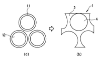
図1は、本発明の多孔質材料の製造方法の一例を模式的に示す説明図であり、(a)は本焼成前、(b)は本焼成後の状態を示している。まず、コーディエライト原料からなる中空状顆粒11(以下、単に「中空状顆粒」と記す。)に、有機バインダー(図示せず)、及び必要に応じて水等を添加して原料混合物とする。
【0023】
なお、本発明にいう「コーディエライト原料」とは、「焼成することによりコーディエライトとなる原料」のことを意味する。得られた原料混合物を、適当な成形方法により所定の形状に成形することによって、図1(a)に示す状態の混合物(成形体)を得る。
【0024】
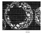
このとき用いる中空状顆粒の平均粒径は特に限定されるものではないが、5〜100μmのものであればよい。図5に、本発明の多孔質材料の製造方法に好適に用いられるコーディエライト原料からなる中空状顆粒の粒子構造の一例である顕微鏡写真を示す。なお、当該中空状顆粒の製造方法については後述する。
【0025】
次いで、図1(a)に示す状態の混合物を本焼成することにより、図1(b)に示すような、球状の気孔4を有するコーディエライト3質の多孔質材料1を得ることができる。このような本発明に係る多孔質材料の製造方法によれば、従来の製造方法による場合と比較して、容易に高気孔率化された多孔質材料を得ることができる。
【0026】
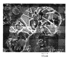
なお、本発明に用いる中空状顆粒は、図1において示すような外周形状に限定されるものではなく、例えば、図2(a)において示すような外周形状であってもよく、その内部に中空部12を有する構造であればよい。図6は、本発明の多孔質材料の製造方法に好適に用いられるコーディエライト原料からなる中空状顆粒の粒子構造の別の例である顕微鏡写真であり、コーディエライト原料に含まれる成分を溶融し、非晶質として凝固させたものをエポキシ樹脂にてコーティング及び硬化した後、その一部を研磨して得られたものである。この粒子構造の顕微鏡写真においては、コーディエライト原料により膜状の殻が形成されているとともに、その芯部には中空部が形成された状態が示されている。
【0027】
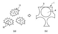
更に、本発明においては、焼成するとコーディエライトとなるコーディエライト原料からなる中空状顆粒を含む原料混合物にセラミックスを添加することが好ましい。図3は、本発明の多孔質材料の製造方法の一例を模式的に示す説明図であり、(a)は本焼成前、(b)は本焼成後の状態を示している。まず、コーディエライト原料からなる中空状顆粒11(以下、単に「中空状顆粒」と記す。)に、セラミックス2、有機バインダー(図示せず)、及び必要に応じて水等を添加して原料混合物とする。
【0028】
このとき用いるセラミックスには、Fe、Ca等の微量の不純物が含有される場合があるが、そのまま使用してもよく、薬品洗浄等の化学的な処理を施して精製したものを用いてもよい。得られた坏土を、適当な成形方法により所定の形状に成形することによって、図3(a)に示す混合状態(成形体)とする。これを本焼成することにより、図3(b)に示すようなコーディエライト3とセラミックス2との結合組織が形成されているとともに、球状の気孔4を有するコーディエライト3質の多孔質材料1を得ることができる。
【0029】
得られた多孔質材料1は結合組織中に骨材としてのセラミックス2を含有しているため、用いるセラミックスの物理的性質、例えば高熱伝導率等が十分に生かされる。また、骨材を含有する結合組織を形成することにより、組織の微構造を強固に支持することが可能となるため、従来の製造方法による場合と比較して容易に高気孔率化された多孔質材料を得ることができる。
【0030】
なお、中空状顆粒及び有機バインダーに、更にセラミックスを添加する場合であっても、中空状顆粒は図3(a)において示すような外周形状に限定されるものではなく、例えば、図4(a)において示すような外周形状であってもよく、その内部に中空部12を有する構造であればよい。
【0031】
また、本発明の多孔質材料の製造方法においては、融点が1400℃以上であるセラミックスを用いることが好ましく、1450℃以上であることが更に好ましく、1500℃以上であることが特に好ましい。即ち、結合材としてのコーディエライトの融点に比して、高融点であるセラミックスが骨材として含有された状態の多孔質材料を得ることができるため、コーディエライトの融点付近の温度で焼成するに際して当該セラミックスが溶融することがなく、結合組織中に分散された状態となる。従って、高温条件下、例えばDPF等として使用する場合において、フィルタ再生のためにパティキュレートを燃焼させても、フィルタを損傷させるような局所的な発熱が生じ難い多孔質材料を提供することができる。
【0032】
なお、本発明においては、用いるセラミックスの融点の上限については特に限定されるものではないが、各種セラミックスの物理的性質を考慮すると、概ね2900℃以下であればよい。
【0033】
本発明の多孔質材料の製造方法においては、セラミックスとして炭化珪素、ムライト、窒化珪素、窒化アルミニウム、アルミナ、スピネル、シリカ、マグネシア、炭化ホウ素、及び窒化ホウ素からなる群より選択される少なくとも1種を用いることが好ましい。これらのセラミックスは入手が容易であるだけでなく、用いることによって得られる多孔質材料に各々の物理的特性を付与することができる。ここでいう物理的特性とは、例えば高熱伝導率、高機械的強度を始めとする特性である。
【0034】
また、用いるセラミックスの形状は、粉末状、粒子状、その他の形状であってもよく、特に限定されるものではないが、その平均粒径は1〜100μmのものを用いることが好ましい。5μm以上であれば容易に所望の気孔率及び気孔径とすることができる。一方、100μmを超えると、その後の成形の際に、成形性が不良となる場合がある。
コーディエライトは焼成時に比較的容易に物質移動する性質を有することから、セラミックスの平均粒径の差異に大きく影響されることなく気孔率及び気孔径を制御することができる。
【0035】
なお、セラミックスとして炭化珪素を用いた場合、得られる多孔質材料を構成する結合組織は、再結晶SiCと同等以上の機械的強度を有することから、結果的に、平均粒径が小さな炭化珪素群がコーディエライトで細長く結合されて大きな細孔を形成する状態になったとしても、ハニカム形状等の薄壁の構造体であっても十分に維持することができる。
【0036】
所望の形状に成形することにより得られた成形体は、次いで、必要に応じて仮焼してもよい。具体的には、150〜700℃程度の所定の温度で一旦保持してもよく、また、所定温度域で昇温速度を50℃/h以下に遅くして仮焼してもよい。また、所定の温度で一旦保持する手法については、使用した有機バインダーの種類と量により、一温度水準のみの保持でも複数温度水準での保持でもよく、更に複数温度水準で保持する場合には、互いに保持時間を同じにしても異ならせてもよい。また、昇温速度を遅くする手法についても同様に、ある一温度区域間のみ遅くしても複数区間で遅くしてもよく、更に複数区間の場合には、互いに速度を同じとしても異ならせてもよい。
【0037】
本発明においては、コーディエライト原料からなる中空状顆粒を含む原料混合物は、適当な成形方法により所望とする形状となるように成形すればよく、例えば押出成形、プレス成形等を始めとする成形方法を好適に採用することができる。
【0038】
このとき、本発明においては、原料混合物を用いてハニカム形状の成形体を得ることが好ましい。即ち、得られる多孔質材料が高熱伝導率、かつ、高気孔率であるといった特徴を生かし、特に、ディーゼルエンジンから排出されるパティキュレートを捕集除去するためのDPFや、触媒担体等として高SV条件下で好適に使用することができる。
【0039】
次いで、本焼成することにより、目的とする多孔質材料を製造することができる。ここで、セラミックスとコーディエライトが結合してなる結合組織を得るためには、中空状顆粒を構成するコーディエライト原料が溶融して、コーディエライトを形成する必要がある。従って、本焼成は1300〜1500℃の温度範囲で実施することが好ましく、1320〜1500℃で実施することが更に好ましく、1350〜1480℃で実施することが特に好ましい。更に最適な焼成温度は、微構造や特性値から決定される。
【0040】
なお、特開平6−182228号公報に示される再結晶法を用いた製造方法によれば、炭化珪素粒子同士で結合した構造を有するために高い熱伝導率の焼結体が得られるが、先に述べたように蒸発凝縮という機構で焼結するので、炭化珪素を蒸発させるために、本発明の製造方法よりも高い焼成温度を必要とし、実用上使用可能な炭化珪素質多孔体を得るためには少なくとも1800℃以上、通常は2000℃以上の高温で焼成する必要がある。
【0041】
次に、本発明の別の実施態様であるコーディエライト原料からなる中空状顆粒の製造方法について説明する。まず、焼成するとコーディエライトとなるコーディエライト原料と成形助剤とを混合して造粒用原料を調製する。次いで、得られた造粒用原料を用いて、スプレードライヤーにより噴霧造粒して中空状顆粒とすることを特徴とするものである。
【0042】
まず、一般的に用いられるコーディエライト原料に成型助剤を添加し、必要に応じて水等を添加することによって造粒用原料を得る。このとき、用いる原料中にはFe、Ca等の微量の不純物が含有される場合があるが、そのまま使用してもよく、薬品洗浄等の化学的な処理を施して精製したものを用いてもよい。
【0043】
本発明においては、成型助剤は、コーディエライト原料に対して外配で1〜20質量%を添加することが好ましく、2〜15質量%を添加することが更に好ましく、5〜10質量%を添加することが特に好ましい。1質量%未満である場合には、得られる中空状顆粒の強度が不充分となり易く、その後の取り扱い時において、顆粒のつぶれを生じ易くなるために好ましくない。一方、20質量%超である場合には、得られる顆粒が中空とならずに、中空部のない中実顆粒となり易くなるために好ましくない。
【0044】
また、本発明において用いる成形助剤としては、ポリビニルアルコール(PVA)、アクリル、及びセルロースからなる群より選択される少なくとも1種を用いることが好ましい。これらの成型助剤は入手、取り扱いが容易であるとともに、効果的に中空状顆粒を得ることができるからである。
【0045】
上述のようにして得られた造粒用原料を、スプレードライヤーにより噴霧造粒する。このとき、造粒用原料は水分中にコーディエライト原料等が分散された状態の液滴状態で加熱域中へと噴霧されるが、噴霧直後に内部に水分を閉じ込めた状態で瞬時に固められる。その後、水分が蒸発することにより、図5に示すような形状的特徴を有する、平均粒径が5〜100μm程度の中空状顆粒が得られる。
【0046】
本発明においては、スプレードライヤーのドライヤー、即ち、造粒用原料が噴霧される加熱域への入口温度を200℃以上に設定する。200℃未満である場合には、温度が低すぎるために得られる顆粒が中空になり難いために好ましくない。なお、入口温度の上限値は、実質的な製造条件やエネルギー効率等を考慮して500℃とする。
【0047】
本発明においては、スプレードライヤーによる噴霧造粒によって得られた中空状顆粒を更に仮焼することが好ましく、このことにより、混合や成形工程の際に加わる応力に抗するだけの強度を発現させることができ、平均粒径が5〜100μm程度の中空状顆粒を得ることができる。
なお、仮焼は一般的な仮焼条件に従って実施すればよいが、具体的には1000〜1200℃、1〜3時間程度行えばよい。但し、仮焼を実施しない場合には、その後に本発明に係る多孔質材料の製造方法に用いた場合に、混合、成形工程の際につぶれを生じ易くなり、高気孔率である多孔質材料を得ることが困難となるために好ましくない。
【0048】
一方、本発明においては、前述の仮焼に代えて成形助剤の結晶化処理を実施することも同様に好ましい。即ち、造粒用原料に含まれる成形助剤を適当な方法によって結晶化することによっても、混合や成形工程の際に加わる応力に抗するだけの強度を発現させることができる。
【0049】
なお、成形助剤の結晶化処理は、用いる成形助剤の種類や添加量等に応じ、一般的な条件に従って実施すればよい。例えば、成形助剤としてPVAを添加した場合には、具体的には125〜175℃、2〜7時間程度行えばよい。仮焼することに代えて結晶化処理を実施することにより、熱処理温度を下げることができるため、多孔質材料の製造コストを低減することも可能となる。
【0050】
【実施例】
以下、本発明を実施例によって更に具体的に説明するが、本発明はこれらの実施例によっていかなる制限を受けるものではない。
(実施例1〜6)
平均粒径15μmのタルク、平均粒径10μmのカオリン、及び平均粒径5μmのアルミナからなるコーディエライト原料に、表1に示す量のポリビニルアルコール(PVA)を外配で添加した。次いで、ドライヤーへの入口温度を250℃としたスプレードライヤーを用いて噴霧造粒を行うことによりコーディエライト原料からなる顆粒を得、更にこの顆粒を1100℃の温度にて2時間仮焼した。これを、表1に示す種類及び平均粒径のセラミックスと、体積比で1:1となるように配合し(但し、実施例2ではセラミックスと配合しない)、有機バインダーとしてメチルセルロース7質量%、界面活性剤1質量%を外配で加え、これを混合及び混練することにより成形用の坏土を得た。得られた坏土を所定の形状に成形した後、窒素雰囲気において1400℃の焼成温度にて2時間の焼成を行い、多孔質材料を作製した。
【0051】
(実施例7)
仮焼することに代えて、成形助剤(PVA)の結晶化処理(150℃、5時間)を実施すること以外は、実施例1〜6と同様の操作手順により、多孔質材料を作製した。
【0052】
(比較例1)
実施例1〜6と同様の組成からなるコーディエライト原料に、平均粒径6.5μmの炭化珪素(SiC)粉末を、体積比で1:1となるように配合し、有機バインダーとしてメチルセルロース7質量%、界面活性剤1質量%を外配で加え、これを混合及び混練することにより成形用の坏土を得た。得られた坏土を所定の形状に成形した後、窒素雰囲気において1400℃の焼成温度にて2時間の焼成を行い、多孔質材料を作製した。
【0053】
(比較例2)
実施例1〜6と同様の組成からなるコーディエライト原料に、有機バインダーとしてメチルセルロース7質量%、界面活性剤1質量%を外配で加え、これを混合及び混練することにより成形用の坏土を得た。得られた坏土を所定の形状に成形した後、大気中1400℃の焼成温度にて2時間の焼成を行い、多孔質材料を作製した。
【0054】
(比較例3)
実施例1〜6と同様の組成からなるコーディエライト原料に、平均粒径40μmのムライトを、体積比で1:1となるように配合し、有機バインダーとしてメチルセルロース7質量%、界面活性剤1質量%を外配で加え、これを混合及び混練することにより成形用の坏土を得た。得られた坏土を所定の形状に成形した後、窒素雰囲気において1400℃の焼成温度にて2時間の焼成を行い、多孔質材料を作製した。
【0055】
(比較例4〜6)
実施例1〜6と同様の組成からなるコーディエライト原料に、表1に示す量のPVAを外配で添加した。次いで、表1に示す入口温度としたスプレードライヤーを用いて噴霧造粒を行うことによりコーディエライト原料からなる顆粒を得、更にこの顆粒を1100℃の温度にて2時間仮焼した。これを、平均粒径6.5μmのSiC粉末と、体積比で1:1となるように配合し、有機バインダーとしてメチルセルロース7質量%、界面活性剤1質量%を外配で加え、これを混合及び混練することにより成形用の坏土を得た。得られた坏土を所定の形状に成形した後、窒素雰囲気において1400℃の焼成温度にて2時間の焼成を行い、多孔質材料を作製した。
【0056】
実施例1〜7及び比較例4〜6の操作途中において得られたコーディエライト原料からなる顆粒の平均粒径(μm)を測定した。また、顆粒の形態(中空又は中実)、及び焼成時によるつぶれの有無について評価を行った。結果を表1に示す。なお、顆粒の形態、及び焼成によるつぶれの有無についての評価方法を以下に示す。
【0057】
[顆粒の形態の評価]:
作製した顆粒を樹脂(エポキシ樹脂)でコーティング及び硬化した後に一部を研磨し、次いで顕微鏡観察することにより、顆粒の形態を評価した。より具体的には、顆粒の平均粒径が20μm以上かつ、タップ密度が0.69g/cm3未満である場合を「中空」、0.69g/cm3以上である場合を「中実」と評価した。なお、図5に、実施例1において作製した顆粒の粒子構造の顕微鏡写真を示す。
【0058】
[焼成による顆粒のつぶれの有無の評価]:
比較例1に示した、中空状顆粒の造粒操作を行わずに一般原料を使用して作製した多孔質材料と比較して、気孔率の増大分が10%以上の場合を、「(つぶれ)なし」、10%未満の場合を「(つぶれ)あり」と評価した。
【0059】
また、実施例1〜7及び比較例1〜6で得られた多孔質材料の気孔率(%)を測定した。同じく結果を表1に示す。なお、コーディエライト原料からなる顆粒の平均粒径(μm)、及び多孔質材料の気孔率(%)の測定方法を以下に示す。
【0060】
[コーディエライト原料からなる顆粒の平均粒径]:
乾式レーザー回折/散乱法にて測定した。
【0061】
[多孔質材料の気孔率]:
アルキメデス法にて測定した。
【0062】
【表1】

(考察)
表1に示す結果から明らかなように、成形助剤として、PVAを1、5、又は20質量%添加した実施例1〜6の場合においては、得られる顆粒が中空であるとともに、その後のハンドリングの際にもつぶれを生ずることはなかった。これに対して、比較例4(PVA添加量:0.5質量%)、比較例5(PVA添加量:25質量%)の場合においては、顆粒につぶれを生ずる、或いは、顆粒が中実となることが判明した。また、スプレードライヤーのドライヤーへの入口温度が200℃未満である比較例5(入口温度:170℃)の場合においても、中空状顆粒を得ることができなかった。
【0064】
実施例1〜7に示す多孔質材料の製造方法においては、いずれの比較例に示す方法と比較しても、高気孔率である多孔質材料とすることができた。
また、骨材としてSiC、ムライトのいずれを用いた場合であっても、多孔質材料を製造可能であることが判明した。
【0065】
【発明の効果】
以上説明したように、本発明の多孔質材料の製造方法によれば、コーディエライト原料からなる中空状顆粒を始めとする所定の原料を用いるため、高気孔率、高熱伝導率である多孔質材料を低コストで簡便に製造することができる。得られた多孔質材料はこれらの物理的特性を生かし、例えば自動車排気ガス浄化用のフィルタや触媒担体等に好適に用いることができる。
また、本発明のコーディエライト原料からなる中空状顆粒の製造方法によれば、所定の原料を使用し、スプレードライヤーを用いた噴霧造粒を実施することにより、前述の多孔質材料の製造に好適に用いることができるコーディエライト原料からなる中空状顆粒を製造することができる。
【図面の簡単な説明】
【図1】 本発明の多孔質材料の製造方法の一例を模式的に示す説明図であり、(a)は本焼成前、(b)は本焼成後の状態を示す。
【図2】 本発明の多孔質材料の製造方法の別の例を模式的に示す説明図であり、(a)は本焼成前、(b)は本焼成後の状態を示す。
【図3】 本発明の多孔質材料の製造方法の更に別の例を模式的に示す説明図であり、(a)は本焼成前、(b)は本焼成後の状態を示す。
【図4】 本発明の多孔質材料の製造方法の更に別の例を模式的に示す説明図であり、(a)は本焼成前、(b)は本焼成後の状態を示す。
【図5】 本発明の多孔質材料の製造方法に好適に用いられるコーディエライト原料からなる中空状顆粒の粒子構造の一例を示す顕微鏡写真である。
【図6】 本発明の多孔質材料の製造方法に好適に用いられるコーディエライト原料からなる中空状顆粒の粒子構造の別の例を示す顕微鏡写真である。
【符号の説明】
1…多孔質材料、2…セラミックス、3…コーディエライト、4…気孔、11…中空状顆粒、12…中空部。[0001]
BACKGROUND OF THE INVENTION
The present invention relates to a method for producing a porous material, and a method for producing a hollow granule comprising a cordierite raw material used in the method for producing the porous material.
[0002]
[Prior art]
A plurality of adjacent filters as a filter for collecting and removing particulate matter in a dust-containing fluid such as diesel engine exhaust gas, or as a catalyst carrier for supporting a catalyst component for purifying harmful substances in exhaust gas. A porous honeycomb structure comprising a cell partition wall (rib) forming a cell composite and a honeycomb outer wall that surrounds and holds the outermost peripheral cell located at the outermost periphery of the cell composite is widely used. In addition, ceramic materials such as silicon carbide (SiC) and cordierite are used as the constituent material.
[0003]
As a specific related technique, for example, in JP-A-6-182228, a silicon carbide powder having a predetermined specific surface area and containing impurities is used as a starting material, which is molded into a desired shape, dried, A honeycomb-structured porous silicon carbide catalyst carrier obtained by firing in a temperature range of 2200 ° C. is disclosed.
[0004]
JP-A-5-213665 discloses a cordierite composite material characterized in that 5 to 40% by weight of a plate-like silicon carbide is present in the cordierite matrix with respect to the content of both. It is disclosed.
[0005]
[Problems to be solved by the invention]
However, in the catalyst carrier disclosed in JP-A-6-182228, in the sintered form (necking) by the recrystallization reaction of the silicon carbide powder itself, the silicon carbide component evaporates from the surface of the silicon carbide particles, and this is between the particles. By condensing in the contact portion (neck portion), the neck portion grows and a bonded state is obtained, but in order to evaporate silicon carbide, a very high firing temperature is required, which leads to high costs, and In addition, since a material having a high coefficient of thermal expansion has to be fired at a high temperature, there is a problem in that the firing yield is lowered.
[0006]
Further, when a filter having a high porosity, particularly a filter having a porosity of 50% or more, is manufactured by sintering the silicon carbide powder itself by recrystallization reaction, the sintering mechanism does not function sufficiently. For this reason, the growth of the neck portion is hindered, resulting in a problem that the strength of the filter is lowered.
[0007]
Furthermore, although the above-mentioned material has a very high thermal conductivity of 30 W / m · K or more and is advantageous in terms of suppressing local heat generation, for example, the catalyst is supported to oxidize and burn particulates, When used for a filter that regenerates continuously, it takes a long time for the temperature of the carrier to rise to the temperature at which the catalyst functions, due to the small amount of particulate accumulation and easy heat dissipation. Since it takes a long time to raise the temperature, there is a problem that particulates remain unburned and the regeneration efficiency is lowered.
[0008]
The cordierite composite material disclosed in JP-A-5-213665 exhibits a certain effect in improving creep characteristics and impact resistance, but has a low silicon carbide content and is thermally conductive. In terms of chemical durability, it was not always satisfactory.
[0009]
Further, with the recent rapid industrial development, there is a demand for improved functions of filters and catalyst carriers. That is, there is a need for a filter or catalyst carrier that has increased collection efficiency and reduced pressure loss. However, in any of the conventional techniques described above, it is difficult to increase the porosity, increase the pore diameter, etc. with the aim of further increasing the collection efficiency and reducing the pressure loss. is there.
[0010]
In order to solve the above problems, in Japanese Patent Laid-Open No. 60-226416, a predetermined raw material solution is sprayed into a flame or the like to produce cordierite glassy powder, which is obtained by molding and sintering. Porous cordierite ceramics are disclosed. Since the porous cordierite ceramic has a high porosity and a spherical shape, the pressure loss is reduced. However, since the material is cordierite, it is not always satisfactory in terms of thermal conductivity and chemical durability.
[0011]
The present invention has been made in view of such problems of the prior art, and its object is to easily produce a porous material having high porosity and high thermal conductivity at low cost. Another object of the present invention is to provide a method for producing a porous material comprising a cordierite raw material that can be suitably used for producing the porous material.
[0012]
[Means for Solving the Problems]
That is, according to the present invention,A raw material for granulation is prepared by mixing a cordierite raw material that becomes cordierite upon firing and a forming aid, and the inlet temperature to the dryer is set to 200 to 500 ° C. using the raw material for granulation. Hollow granules made of cordierite raw material, which are spray-granulated with a spray dryer to form hollow granulesA manufacturing method is provided.
[0013]
In the present invention, it is preferable to add 1 to 20% by mass of a molding aid externally to the cordierite raw material.
[0014]
In the present invention, at least one selected from the group consisting of polyvinyl alcohol (PVA), acrylic, and cellulose is preferably used as a molding aid.
[0015]
In the present invention, it is preferable to perform calcining after spray granulation with a spray dryer, or it is preferable to perform crystallization treatment of the molding aid instead of calcining.
[0016]
On the other hand, according to the present invention,A molded body having a predetermined shape is obtained using a raw material mixture containing hollow granules manufactured by the above-described manufacturing method, which is made of a cordierite raw material that becomes cordierite when fired, and the obtained molded body is subjected to main firing. Porous material characterized byA manufacturing method is provided.
[0017]
In the present invention, it is preferable to add ceramics to the raw material mixture, and it is preferable to add ceramics having a melting point of 1400 ° C. or higher.
[0018]
Furthermore, in the present invention, it is preferable to use at least one selected from the group consisting of silicon carbide, mullite, silicon nitride, aluminum nitride, alumina, spinel, silica, magnesia, boron carbide, and boron nitride as ceramics.
[0019]
In the present invention, it is preferable to obtain a honeycomb-shaped formed body using the raw material mixture, and it is preferable to perform the main firing in a temperature range of 1300 to 1500 ° C.
[0020]
DETAILED DESCRIPTION OF THE INVENTION
Hereinafter, embodiments of the present invention will be described. However, the present invention is not limited to the following embodiments, and may be appropriately selected based on ordinary knowledge of those skilled in the art without departing from the spirit of the present invention. It should be understood that design changes, improvements, etc. may be made.
[0021]
One embodiment of the present invention is a method for producing a porous material, comprising a cordierite raw material that becomes cordierite when fired., Produced by “Method for producing hollow granules comprising cordierite raw material” described laterA molded body having a predetermined shape is obtained using a raw material mixture containing hollow granules, and the molded body is subjected to main firing. The details will be described below.
[0022]
FIG. 1 is an explanatory view schematically showing an example of a method for producing a porous material of the present invention, in which (a) shows a state before the main baking, and (b) shows a state after the main baking. First, an organic binder (not shown) and water as required are added to a hollow granule 11 (hereinafter simply referred to as “hollow granule”) made of cordierite raw material to obtain a raw material mixture. .
[0023]
The “cordierite raw material” in the present invention means “a raw material that becomes cordierite by firing”. The obtained raw material mixture is molded into a predetermined shape by an appropriate molding method to obtain a mixture (molded body) in the state shown in FIG.
[0024]
The average particle size of the hollow granules used at this time is not particularly limited, but may be 5 to 100 μm. In FIG. 5, the microscope picture which is an example of the particle structure of the hollow granule which consists of a cordierite raw material used suitably for the manufacturing method of the porous material of this invention is shown. In addition, the manufacturing method of the said hollow granule is mentioned later.
[0025]
Next, the mixture in the state shown in FIG. 1 (a) is subjected to main firing, whereby a cordierite-like
[0026]
The hollow granules used in the present invention are not limited to the outer peripheral shape as shown in FIG. 1, but may be, for example, the outer peripheral shape as shown in FIG. Any structure having the
[0027]
Furthermore, in the present invention, it is preferable to add ceramics to a raw material mixture containing hollow granules made of cordierite raw material that becomes cordierite when fired. FIG. 3 is an explanatory view schematically showing an example of the method for producing a porous material of the present invention, wherein (a) shows a state before the main baking, and (b) shows a state after the main baking. First, a
[0028]
Ceramics used at this time may contain a small amount of impurities such as Fe and Ca, but they may be used as they are, or those purified by chemical treatment such as chemical cleaning may be used. . The obtained clay is formed into a predetermined shape by an appropriate forming method to obtain a mixed state (formed body) shown in FIG. When this is fired, a
[0029]
Since the obtained
[0030]
Even when ceramics are further added to the hollow granule and the organic binder, the hollow granule is not limited to the outer peripheral shape as shown in FIG. 3A. For example, FIG. The outer peripheral shape as shown in FIG. 2 may be used, and any structure having the
[0031]
In the method for producing a porous material of the present invention, it is preferable to use ceramics having a melting point of 1400 ° C. or higher, more preferably 1450 ° C. or higher, and particularly preferably 1500 ° C. or higher. That is, since a porous material containing ceramics having a high melting point as an aggregate can be obtained as compared with the melting point of cordierite as a binder, firing is performed at a temperature near the melting point of cordierite. In this case, the ceramic is not melted and is dispersed in the connective tissue. Therefore, when used as a DPF or the like under high temperature conditions, it is possible to provide a porous material that hardly generates local heat that damages the filter even if the particulates are burned for filter regeneration. .
[0032]
In the present invention, the upper limit of the melting point of the ceramic to be used is not particularly limited. However, considering the physical properties of various ceramics, it may be approximately 2900 ° C. or lower.
[0033]
In the method for producing a porous material of the present invention, the ceramic is at least one selected from the group consisting of silicon carbide, mullite, silicon nitride, aluminum nitride, alumina, spinel, silica, magnesia, boron carbide, and boron nitride. It is preferable to use it. These ceramics are not only easily available, but can also impart physical properties to the porous material obtained by using them. The physical characteristics referred to here are characteristics such as high thermal conductivity and high mechanical strength.
[0034]
Further, the shape of the ceramic to be used may be powder, particle, or other shape, and is not particularly limited, but it is preferable to use one having an average particle diameter of 1 to 100 μm. If it is 5 micrometers or more, it can be set as a desired porosity and a pore diameter easily. On the other hand, if it exceeds 100 μm, the moldability may be poor during subsequent molding.
Since cordierite has the property of mass transfer relatively easily during firing, the porosity and the pore diameter can be controlled without being greatly affected by the difference in the average particle diameter of the ceramics.
[0035]
When silicon carbide is used as the ceramic, the connective structure constituting the obtained porous material has a mechanical strength equal to or higher than that of recrystallized SiC, and as a result, a silicon carbide group having a small average particle size. However, even if it becomes a state in which long cords are combined with cordierite to form large pores, even a thin wall structure such as a honeycomb shape can be sufficiently maintained.
[0036]
The molded body obtained by molding into a desired shape may then be calcined as necessary. Specifically, it may be temporarily held at a predetermined temperature of about 150 to 700 ° C., or may be calcined at a temperature rising rate of 50 ° C./h or less in a predetermined temperature range. In addition, for the method of temporarily holding at a predetermined temperature, depending on the type and amount of the organic binder used, it may be held only at one temperature level or held at multiple temperature levels, and when holding at multiple temperature levels, The holding times may be the same or different. Similarly, the method of slowing the rate of temperature rise may be slowed only in one temperature zone or slowed down in a plurality of sections. Further, in the case of a plurality of sections, the speeds may be different even if they are the same. Also good.
[0037]
In the present invention, the raw material mixture containing hollow granules made of cordierite raw material may be molded into a desired shape by an appropriate molding method, for example, molding such as extrusion molding and press molding. The method can be suitably employed.
[0038]
At this time, in the present invention, it is preferable to obtain a honeycomb-shaped formed body using the raw material mixture. That is, taking advantage of the feature that the obtained porous material has a high thermal conductivity and a high porosity, in particular, a high SV as a DPF for collecting and removing particulates discharged from a diesel engine, a catalyst carrier or the like. It can be suitably used under conditions.
[0039]
Subsequently, the target porous material can be manufactured by this baking. Here, in order to obtain a connective structure formed by bonding ceramics and cordierite, the cordierite raw material constituting the hollow granules needs to be melted to form cordierite. Therefore, the main calcination is preferably performed in a temperature range of 1300 to 1500 ° C., more preferably performed at 1320 to 1500 ° C., and particularly preferably performed at 1350 to 1480 ° C. Furthermore, the optimum firing temperature is determined from the microstructure and characteristic values.
[0040]
Incidentally, according to the manufacturing method using the recrystallization method disclosed in JP-A-6-182228, a sintered body having a high thermal conductivity can be obtained because it has a structure in which silicon carbide particles are bonded to each other. In order to obtain a silicon carbide based porous material that requires a higher firing temperature than the production method of the present invention and is practically usable in order to evaporate silicon carbide. Requires firing at a high temperature of at least 1800 ° C or higher, usually 2000 ° C or higher.
[0041]
Next, the manufacturing method of the hollow granule which consists of a cordierite raw material which is another embodiment of this invention is demonstrated. First, a raw material for granulation is prepared by mixing a cordierite raw material that becomes cordierite when fired and a molding aid. Next, the obtained granulation raw material is used for spray granulation with a spray dryer to form hollow granules.
[0042]
First, a granulating raw material is obtained by adding a molding aid to a commonly used cordierite raw material and adding water or the like as necessary. At this time, the raw material to be used may contain a small amount of impurities such as Fe and Ca, but they may be used as they are, or may be used after being purified by chemical treatment such as chemical cleaning. Good.
[0043]
In the present invention, the molding assistant is preferably added in an amount of 1 to 20% by mass, more preferably 2 to 15% by mass, more preferably 5 to 10% by mass with respect to the cordierite raw material. It is particularly preferable to add If it is less than 1% by mass, the strength of the resulting hollow granule tends to be insufficient, and the granule tends to collapse during subsequent handling, which is not preferable. On the other hand, when it is more than 20% by mass, the resulting granule does not become hollow, and it tends to be a solid granule having no hollow portion, which is not preferable.
[0044]
Moreover, it is preferable to use at least 1 sort (s) selected from the group which consists of polyvinyl alcohol (PVA), an acryl, and a cellulose as a shaping | molding adjuvant used in this invention. This is because these molding aids are easily available and handled, and hollow granules can be obtained effectively.
[0045]
The granulation raw material obtained as described above is spray granulated with a spray dryer. At this time, the raw material for granulation is sprayed into the heating zone in the form of droplets in which the cordierite raw material and the like are dispersed in moisture, but immediately after spraying, the moisture is confined instantaneously in a state where moisture is confined inside. It is done. Thereafter, when the water evaporates, hollow granules having a shape characteristic as shown in FIG. 5 and an average particle diameter of about 5 to 100 μm are obtained.
[0046]
In the present invention, the dryer temperature of the spray dryer, that is, the inlet temperature to the heating zone where the granulation raw material is sprayed is set to 200 ° C. or higher.TheWhen the temperature is lower than 200 ° C., the temperature is too low, and thus the obtained granules are difficult to be hollow, which is not preferable. In addition, EnterUpper limit of mouth temperatureIsConsidering actual manufacturing conditions and energy efficiencydo it500 ° CTo.
[0047]
In the present invention, it is preferable that the hollow granules obtained by spray granulation with a spray dryer are further calcined, thereby exhibiting strength sufficient to resist the stress applied during the mixing and molding process. Hollow granules having an average particle diameter of about 5 to 100 μm can be obtained.
In addition, what is necessary is just to implement calcination according to general calcination conditions, but specifically, it may be performed at 1000 to 1200 ° C. for about 1 to 3 hours. However, when calcining is not carried out, when used in the method for producing a porous material according to the present invention, the porous material is likely to be crushed during the mixing and molding process and has a high porosity. It is not preferable because it becomes difficult to obtain.
[0048]
On the other hand, in the present invention, it is also preferable to carry out the crystallization treatment of the molding aid instead of the above-mentioned calcination. That is, the strength sufficient to withstand the stress applied during the mixing or molding process can also be expressed by crystallizing the molding aid contained in the raw material for granulation by an appropriate method.
[0049]
In addition, what is necessary is just to implement the crystallization process of a shaping | molding adjuvant according to general conditions according to the kind, addition amount, etc. of the shaping | molding adjuvant to be used. For example, when PVA is added as a molding aid, specifically, it may be performed at 125 to 175 ° C. for about 2 to 7 hours. By performing the crystallization treatment instead of calcination, the heat treatment temperature can be lowered, so that the manufacturing cost of the porous material can be reduced.
[0050]
【Example】
EXAMPLES Hereinafter, the present invention will be described more specifically with reference to examples. However, the present invention is not limited to these examples.
(Examples 1-6)
Polyvinyl alcohol (PVA) in the amount shown in Table 1 was added externally to a cordierite raw material consisting of talc having an average particle diameter of 15 μm, kaolin having an average particle diameter of 10 μm, and alumina having an average particle diameter of 5 μm. Subsequently, the granulation which consists of a cordierite raw material was obtained by performing spray granulation using the spray dryer which set the inlet_port | entrance temperature to a dryer to 250 degreeC, Furthermore, this granule was calcined for 2 hours at the temperature of 1100 degreeC. This was blended with ceramics of the types and average particle diameters shown in Table 1 so that the volume ratio was 1: 1 (however, not blended with ceramics in Example 2), 7% by mass of methylcellulose as an organic binder,
[0051]
(Example 7)
A porous material was produced by the same operation procedure as in Examples 1 to 6, except that a crystallization treatment (150 ° C., 5 hours) of the molding aid (PVA) was performed instead of calcination. .
[0052]
(Comparative Example 1)
In a cordierite raw material having the same composition as in Examples 1 to 6, silicon carbide (SiC) powder having an average particle diameter of 6.5 μm is blended so as to have a volume ratio of 1: 1. Mass% and 1% by mass of a surfactant were added externally and mixed and kneaded to obtain a clay for molding. The obtained clay was molded into a predetermined shape, and then fired at a firing temperature of 1400 ° C. for 2 hours in a nitrogen atmosphere to produce a porous material.
[0053]
(Comparative Example 2)
A cordierite raw material having the same composition as in Examples 1 to 6 is added with 7% by mass of methylcellulose and 1% by mass of a surfactant as an organic binder, and mixed and kneaded to form a clay for molding. Got. The obtained clay was molded into a predetermined shape, and then fired at a firing temperature of 1400 ° C. in the atmosphere for 2 hours to produce a porous material.
[0054]
(Comparative Example 3)
In the cordierite raw material having the same composition as in Examples 1 to 6, mullite having an average particle size of 40 μm is blended so as to have a volume ratio of 1: 1, and 7% by mass of methyl cellulose as an organic binder,
[0055]
(Comparative Examples 4-6)
The amount of PVA shown in Table 1 was added externally to a cordierite raw material having the same composition as in Examples 1 to 6. Next, spray granulation was performed using a spray dryer having the inlet temperature shown in Table 1 to obtain granules made of cordierite raw material, and the granules were calcined at a temperature of 1100 ° C. for 2 hours. This is blended with SiC powder having an average particle diameter of 6.5 μm so as to have a volume ratio of 1: 1, and 7% by mass of methylcellulose and 1% by mass of a surfactant are externally added as an organic binder and mixed. And kneading was obtained by kneading. The obtained clay was molded into a predetermined shape, and then fired at a firing temperature of 1400 ° C. for 2 hours in a nitrogen atmosphere to produce a porous material.
[0056]
The average particle diameter (micrometer) of the granule which consists of a cordierite raw material obtained in the middle of operation of Examples 1-7 and Comparative Examples 4-6 was measured. Moreover, it evaluated about the form (hollow or solid) of a granule, and the presence or absence of the crushing at the time of baking. The results are shown in Table 1. In addition, the evaluation method about the form of a granule and the presence or absence of crushing by baking is shown below.
[0057]
[Evaluation of granule morphology]:
The prepared granules were coated with a resin (epoxy resin) and cured, and then part of the granules were polished and then observed under a microscope to evaluate the morphology of the granules. More specifically, the average particle diameter of the granules is 20 μm or more and the tap density is 0.69 g / cm.ThreeIf it is less than “hollow”, 0.69 g / cmThreeThe above cases were evaluated as “solid”. In addition, in FIG. 5, the microscope picture of the particle structure of the granule produced in Example 1 is shown.
[0058]
[Evaluation of whether or not the granules are crushed by firing]:
Compared with the porous material produced by using a general raw material without performing the granulation operation of the hollow granule shown in Comparative Example 1, the increase in porosity is 10% or more. ) None ”and the case of less than 10% was evaluated as“ (crushed) ”.
[0059]
Moreover, the porosity (%) of the porous material obtained in Examples 1-7 and Comparative Examples 1-6 was measured. Similarly, the results are shown in Table 1. In addition, the measuring method of the average particle diameter (micrometer) of the granule which consists of a cordierite raw material, and the porosity (%) of a porous material is shown below.
[0060]
[Average particle size of granules made of cordierite raw material]:
Measurement was performed by a dry laser diffraction / scattering method.
[0061]
[Porosity of porous material]:
It was measured by Archimedes method.
[0062]
[Table 1]
(Discussion)
As is apparent from the results shown in Table 1, in the case of Examples 1 to 6 in which 1, 5 or 20% by mass of PVA was added as a molding aid, the resulting granules were hollow and the subsequent handling There was no crushing on the occasion. On the other hand, in the case of Comparative Example 4 (PVA addition amount: 0.5% by mass) and Comparative Example 5 (PVA addition amount: 25% by mass), the granules are crushed or the granules are solid. Turned out to be. Also, in the case of Comparative Example 5 (inlet temperature: 170 ° C.) in which the inlet temperature of the spray dryer to the dryer was less than 200 ° C., hollow granules could not be obtained.
[0064]
In the manufacturing method of the porous material shown in Examples 1-7, even if it compared with the method shown in any comparative example, it was able to be set as the porous material which is a high porosity.
It has also been found that a porous material can be produced regardless of whether SiC or mullite is used as the aggregate.
[0065]
【The invention's effect】
As described above, according to the method for producing a porous material of the present invention, since a predetermined raw material such as hollow granules made of cordierite raw material is used, a porous material having high porosity and high thermal conductivity is used. The material can be easily manufactured at low cost. The obtained porous material takes advantage of these physical characteristics, and can be suitably used for, for example, an automobile exhaust gas purification filter, a catalyst carrier, and the like.
In addition, according to the method for producing hollow granules comprising the cordierite raw material of the present invention, by using a predetermined raw material and carrying out spray granulation using a spray dryer, the above porous material can be produced. Hollow granules made of cordierite raw material that can be suitably used can be produced.
[Brief description of the drawings]
BRIEF DESCRIPTION OF DRAWINGS FIG. 1 is an explanatory view schematically showing an example of a method for producing a porous material of the present invention, where (a) shows a state before main firing and (b) shows a state after main firing.
FIG. 2 is an explanatory view schematically showing another example of the method for producing a porous material of the present invention, in which (a) shows a state before the main baking, and (b) shows a state after the main baking.
FIGS. 3A and 3B are explanatory views schematically showing still another example of the method for producing a porous material according to the present invention, wherein FIG. 3A shows a state before the main baking, and FIG. 3B shows a state after the main baking.
FIGS. 4A and 4B are explanatory views schematically showing still another example of the method for producing a porous material of the present invention, in which FIG. 4A shows a state before the main baking, and FIG. 4B shows a state after the main baking.
FIG. 5 is a photomicrograph showing an example of the particle structure of hollow granules made of cordierite raw material suitably used in the method for producing a porous material of the present invention.
FIG. 6 is a photomicrograph showing another example of the particle structure of a hollow granule made of cordierite material suitably used in the method for producing a porous material of the present invention.
[Explanation of symbols]
DESCRIPTION OF
Claims (11)
該造粒用原料を用いて、ドライヤーへの入口温度を200〜500℃に設定してスプレードライヤーにより噴霧造粒して中空状顆粒とすることを特徴とするコーディエライト原料からなる中空状顆粒の製造方法。A raw material for granulation is prepared by mixing a cordierite raw material that becomes cordierite when fired and a molding aid,
A hollow granule made of a cordierite raw material, wherein the granulation raw material is used, and the inlet temperature to the dryer is set to 200 to 500 ° C. and is spray-granulated by a spray dryer to form a hollow granule Manufacturing method.
得られた該成形体を本焼成することを特徴とする多孔質材料の製造方法。A molded body having a predetermined shape is obtained using a raw material mixture containing hollow granules produced by the production method according to any one of claims 1 to 5, which comprises a cordierite raw material that becomes cordierite when fired. ,
A method for producing a porous material, comprising subjecting the obtained molded body to main firing.
Priority Applications (1)
| Application Number | Priority Date | Filing Date | Title |
|---|---|---|---|
| JP2001230827A JP4455786B2 (en) | 2001-07-31 | 2001-07-31 | Method for producing porous material and method for producing hollow granules used therefor |
Applications Claiming Priority (1)
| Application Number | Priority Date | Filing Date | Title |
|---|---|---|---|
| JP2001230827A JP4455786B2 (en) | 2001-07-31 | 2001-07-31 | Method for producing porous material and method for producing hollow granules used therefor |
Publications (2)
| Publication Number | Publication Date |
|---|---|
| JP2003040691A JP2003040691A (en) | 2003-02-13 |
| JP4455786B2 true JP4455786B2 (en) | 2010-04-21 |
Family
ID=19062970
Family Applications (1)
| Application Number | Title | Priority Date | Filing Date |
|---|---|---|---|
| JP2001230827A Expired - Fee Related JP4455786B2 (en) | 2001-07-31 | 2001-07-31 | Method for producing porous material and method for producing hollow granules used therefor |
Country Status (1)
| Country | Link |
|---|---|
| JP (1) | JP4455786B2 (en) |
Cited By (1)
| Publication number | Priority date | Publication date | Assignee | Title |
|---|---|---|---|---|
| CN107285748A (en) * | 2017-06-22 | 2017-10-24 | 府谷县旭丽机电技术有限公司 | A kind of preparation method for being used to emulsify the ceramic composite of pump plunger |
Families Citing this family (10)
| Publication number | Priority date | Publication date | Assignee | Title |
|---|---|---|---|---|
| JP5008068B2 (en) * | 2007-03-20 | 2012-08-22 | 独立行政法人物質・材料研究機構 | Porous composite and method for producing the same |
| CN102908977B (en) * | 2012-11-12 | 2015-08-26 | 江西理工大学 | A kind of preparation method of hollow spherical magnesium oxide adsorbent |
| US9623360B2 (en) | 2013-05-20 | 2017-04-18 | Corning Incorporated | Porous ceramic article and method of manufacturing the same |
| US9376347B2 (en) | 2013-05-20 | 2016-06-28 | Corning Incorporated | Porous ceramic article and method of manufacturing the same |
| US9908260B2 (en) * | 2013-05-20 | 2018-03-06 | Corning Incorporated | Porous ceramic article and method of manufacturing the same |
| US10252441B2 (en) | 2013-08-28 | 2019-04-09 | Corning Incorporated | System and method for cutting a wet green ceramic article |
| KR101567311B1 (en) | 2014-10-21 | 2015-11-09 | 주식회사 원익큐엔씨 | Seramic material component and manufacturing method thereof |
| US11229902B2 (en) | 2016-05-31 | 2022-01-25 | Corning Incorporated | Porous article and method of manufacturing the same |
| JP7396989B2 (en) | 2017-10-31 | 2023-12-12 | コーニング インコーポレイテッド | Batch composition comprising pre-reacted spherical inorganic particles and spherical pore forming agent and method for producing honeycomb bodies therefrom |
| CN115959909B (en) * | 2022-12-09 | 2023-08-22 | 武汉科技大学 | B (B) 4 C-mullite-NbB 2 Composite ceramic and preparation method thereof |
-
2001
- 2001-07-31 JP JP2001230827A patent/JP4455786B2/en not_active Expired - Fee Related
Cited By (1)
| Publication number | Priority date | Publication date | Assignee | Title |
|---|---|---|---|---|
| CN107285748A (en) * | 2017-06-22 | 2017-10-24 | 府谷县旭丽机电技术有限公司 | A kind of preparation method for being used to emulsify the ceramic composite of pump plunger |
Also Published As
| Publication number | Publication date |
|---|---|
| JP2003040691A (en) | 2003-02-13 |
Similar Documents
| Publication | Publication Date | Title |
|---|---|---|
| US7208108B2 (en) | Method for producing porous ceramic article | |
| KR100607481B1 (en) | Porous material and method for production thereof | |
| JP4459052B2 (en) | Diesel particulate filter made of mullite / aluminum titanate | |
| KR100931755B1 (en) | Strontium Feldspa Aluminum Titanate for High Temperature | |
| JP5478259B2 (en) | Silicon carbide based porous material | |
| CN105008050B (en) | Ceramic honeycomb structural body and its manufacture method | |
| JP4495152B2 (en) | Honeycomb structure and manufacturing method thereof | |
| JP3150928B2 (en) | Method for manufacturing thin-walled cordierite-based honeycomb structure | |
| JP4094824B2 (en) | Honeycomb ceramic filter | |
| JP5095215B2 (en) | Porous body manufacturing method, porous body and honeycomb structure | |
| WO2002070433A1 (en) | Honeycomb structure | |
| WO2002041972A1 (en) | Porous honeycomb filter and method for manufacture thereof | |
| JP2002154876A (en) | Honeycomb structure and method for producing the same | |
| JP4455786B2 (en) | Method for producing porous material and method for producing hollow granules used therefor | |
| JP2008043852A (en) | Ceramics filter | |
| US6933255B2 (en) | Beta-spodumene ceramics for high temperature applications | |
| JP2009143763A (en) | Silicon carbide-based porous body | |
| JPWO2005068396A1 (en) | Honeycomb structure and manufacturing method thereof | |
| JP2004292197A (en) | Method of manufacturing honeycomb structure | |
| JP5128989B2 (en) | Cordierite ceramics manufacturing method | |
| JP2008239408A (en) | Heat-resistant ceramic member | |
| JP2005059000A (en) | Silicon nitride honeycomb filter and manufacturing method therefor |
Legal Events
| Date | Code | Title | Description |
|---|---|---|---|
| A621 | Written request for application examination |
Free format text: JAPANESE INTERMEDIATE CODE: A621 Effective date: 20070222 |
|
| A977 | Report on retrieval |
Free format text: JAPANESE INTERMEDIATE CODE: A971007 Effective date: 20091019 |
|
| A131 | Notification of reasons for refusal |
Free format text: JAPANESE INTERMEDIATE CODE: A131 Effective date: 20091027 |
|
| A521 | Written amendment |
Free format text: JAPANESE INTERMEDIATE CODE: A523 Effective date: 20091224 |
|
| TRDD | Decision of grant or rejection written | ||
| A01 | Written decision to grant a patent or to grant a registration (utility model) |
Free format text: JAPANESE INTERMEDIATE CODE: A01 Effective date: 20100202 |
|
| A01 | Written decision to grant a patent or to grant a registration (utility model) |
Free format text: JAPANESE INTERMEDIATE CODE: A01 |
|
| A61 | First payment of annual fees (during grant procedure) |
Free format text: JAPANESE INTERMEDIATE CODE: A61 Effective date: 20100204 |
|
| FPAY | Renewal fee payment (event date is renewal date of database) |
Free format text: PAYMENT UNTIL: 20130212 Year of fee payment: 3 |
|
| R150 | Certificate of patent or registration of utility model |
Ref document number: 4455786 Country of ref document: JP Free format text: JAPANESE INTERMEDIATE CODE: R150 Free format text: JAPANESE INTERMEDIATE CODE: R150 |
|
| FPAY | Renewal fee payment (event date is renewal date of database) |
Free format text: PAYMENT UNTIL: 20130212 Year of fee payment: 3 |
|
| LAPS | Cancellation because of no payment of annual fees |