JP4453771B2 - T-section steel manufacturing method and rolling equipment line - Google Patents
T-section steel manufacturing method and rolling equipment line Download PDFInfo
- Publication number
- JP4453771B2 JP4453771B2 JP2008132900A JP2008132900A JP4453771B2 JP 4453771 B2 JP4453771 B2 JP 4453771B2 JP 2008132900 A JP2008132900 A JP 2008132900A JP 2008132900 A JP2008132900 A JP 2008132900A JP 4453771 B2 JP4453771 B2 JP 4453771B2
- Authority
- JP
- Japan
- Prior art keywords
- web
- rolling
- roll
- rolling mill
- flange
- Prior art date
- Legal status (The legal status is an assumption and is not a legal conclusion. Google has not performed a legal analysis and makes no representation as to the accuracy of the status listed.)
- Active
Links
- 238000005096 rolling process Methods 0.000 title claims description 288
- 229910000831 Steel Inorganic materials 0.000 title claims description 61
- 239000010959 steel Substances 0.000 title claims description 61
- 238000004519 manufacturing process Methods 0.000 title claims description 19
- 239000000463 material Substances 0.000 claims description 19
- 238000010586 diagram Methods 0.000 description 13
- 238000005098 hot rolling Methods 0.000 description 11
- 238000007493 shaping process Methods 0.000 description 10
- 238000000034 method Methods 0.000 description 6
- 238000003825 pressing Methods 0.000 description 5
- 230000000052 comparative effect Effects 0.000 description 3
- 238000005520 cutting process Methods 0.000 description 3
- 235000014676 Phragmites communis Nutrition 0.000 description 2
- 238000010438 heat treatment Methods 0.000 description 2
- 230000000694 effects Effects 0.000 description 1
- 238000002474 experimental method Methods 0.000 description 1
- 230000002349 favourable effect Effects 0.000 description 1
- 238000009419 refurbishment Methods 0.000 description 1
- 238000003466 welding Methods 0.000 description 1
- 230000037303 wrinkles Effects 0.000 description 1
Images


Classifications
-
- B—PERFORMING OPERATIONS; TRANSPORTING
- B21—MECHANICAL METAL-WORKING WITHOUT ESSENTIALLY REMOVING MATERIAL; PUNCHING METAL
- B21B—ROLLING OF METAL
- B21B1/00—Metal-rolling methods or mills for making semi-finished products of solid or profiled cross-section; Sequence of operations in milling trains; Layout of rolling-mill plant, e.g. grouping of stands; Succession of passes or of sectional pass alternations
- B21B1/08—Metal-rolling methods or mills for making semi-finished products of solid or profiled cross-section; Sequence of operations in milling trains; Layout of rolling-mill plant, e.g. grouping of stands; Succession of passes or of sectional pass alternations for rolling structural sections, i.e. work of special cross-section, e.g. angle steel
- B21B1/092—T-sections
-
- B—PERFORMING OPERATIONS; TRANSPORTING
- B21—MECHANICAL METAL-WORKING WITHOUT ESSENTIALLY REMOVING MATERIAL; PUNCHING METAL
- B21B—ROLLING OF METAL
- B21B1/00—Metal-rolling methods or mills for making semi-finished products of solid or profiled cross-section; Sequence of operations in milling trains; Layout of rolling-mill plant, e.g. grouping of stands; Succession of passes or of sectional pass alternations
- B21B1/08—Metal-rolling methods or mills for making semi-finished products of solid or profiled cross-section; Sequence of operations in milling trains; Layout of rolling-mill plant, e.g. grouping of stands; Succession of passes or of sectional pass alternations for rolling structural sections, i.e. work of special cross-section, e.g. angle steel
- B21B1/12—Metal-rolling methods or mills for making semi-finished products of solid or profiled cross-section; Sequence of operations in milling trains; Layout of rolling-mill plant, e.g. grouping of stands; Succession of passes or of sectional pass alternations for rolling structural sections, i.e. work of special cross-section, e.g. angle steel in a continuous process, i.e. without reversing stands
-
- B—PERFORMING OPERATIONS; TRANSPORTING
- B21—MECHANICAL METAL-WORKING WITHOUT ESSENTIALLY REMOVING MATERIAL; PUNCHING METAL
- B21B—ROLLING OF METAL
- B21B13/00—Metal-rolling stands, i.e. an assembly composed of a stand frame, rolls, and accessories
- B21B13/06—Metal-rolling stands, i.e. an assembly composed of a stand frame, rolls, and accessories with axes of rolls arranged vertically, e.g. edgers
-
- B—PERFORMING OPERATIONS; TRANSPORTING
- B21—MECHANICAL METAL-WORKING WITHOUT ESSENTIALLY REMOVING MATERIAL; PUNCHING METAL
- B21B—ROLLING OF METAL
- B21B13/00—Metal-rolling stands, i.e. an assembly composed of a stand frame, rolls, and accessories
- B21B13/08—Metal-rolling stands, i.e. an assembly composed of a stand frame, rolls, and accessories with differently-directed roll axes, e.g. for the so-called "universal" rolling process
-
- B—PERFORMING OPERATIONS; TRANSPORTING
- B21—MECHANICAL METAL-WORKING WITHOUT ESSENTIALLY REMOVING MATERIAL; PUNCHING METAL
- B21B—ROLLING OF METAL
- B21B2203/00—Auxiliary arrangements, devices or methods in combination with rolling mills or rolling methods
- B21B2203/18—Rolls or rollers
-
- B—PERFORMING OPERATIONS; TRANSPORTING
- B21—MECHANICAL METAL-WORKING WITHOUT ESSENTIALLY REMOVING MATERIAL; PUNCHING METAL
- B21B—ROLLING OF METAL
- B21B2263/00—Shape of product
- B21B2263/02—Profile, e.g. of plate, hot strip, sections
Landscapes
- Engineering & Computer Science (AREA)
- Mechanical Engineering (AREA)
- Metal Rolling (AREA)
- Reduction Rolling/Reduction Stand/Operation Of Reduction Machine (AREA)
Description
本発明は、熱間圧延によるT形鋼の製造方法および圧延設備に関する。 The present invention relates to a method for manufacturing a T-shaped steel by hot rolling and rolling equipment.
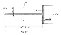
図9にT形鋼の断面形状を示す。T形鋼10はウェブ11とフランジ12からなる断面がT字形状の形鋼であり、造船や橋梁等の分野で広く使用され、その用途や使用条件、使用箇所等によって様々な寸法の製品が製造されている。
FIG. 9 shows the cross-sectional shape of the T-section steel. The T-
通常用いられるT形鋼の寸法は、ウェブ高さ:200〜1000mm程度、ウェブ厚:8〜25mm程度、ウェブ内法寸法:190〜980mm程度、フランジ幅:80〜400mm程度、フランジ厚:12〜40mm程度である。さらに、造船用として用いられるT形鋼の場合、ウェブ高さはフランジ幅の2倍以上であることが多い。 The dimensions of the T-shaped steel that is usually used are as follows: web height: about 200 to 1000 mm, web thickness: about 8 to 25 mm, internal web dimension: about 190 to 980 mm, flange width: about 80 to 400 mm, flange thickness: 12 to 12. It is about 40 mm. Furthermore, in the case of a T-shaped steel used for shipbuilding, the web height is often more than twice the flange width.
また、ウェブ11とフランジ12とを溶接して製造されることが一般的であるが、圧延にてT形鋼を一体成形する技術も提案されている。
Moreover, although it is common to manufacture by welding the
例えば、ウェブ厚、フランジ厚、ウェブ高さおよびフランジ幅が様々な寸法のT形鋼を効率よく製造するため、ユニバーサル圧延機を中間圧延工程と仕上圧延工程に1基ずつ配置した熱間圧延設備が提案されている(例えば特許文献1)。 For example, in order to efficiently produce T-shaped steels with various web thicknesses, flange thicknesses, web heights and flange widths, a hot rolling facility in which one universal rolling mill is arranged in each of the intermediate rolling process and the finishing rolling process. Has been proposed (for example, Patent Document 1).
図10は、その一例を示し、加熱炉(図示しない)から搬出された素材鋼片を往復圧延して断面略T形に粗成形する粗造形圧延機1と、この粗造形圧延機1により略T形形状に粗成形したT形鋼片(図示しない)を略製品寸法のT形鋼に成形するための粗ユニバーサル圧延機2、粗ユニバーサル圧延機2の下流に近設されたエッジャ圧延機3および仕上ユニバーサル圧延機5を備える(図10(a))。
FIG. 10 shows an example thereof, and a rough shaping rolling mill 1 that reciprocally rolls a raw steel piece carried out from a heating furnace (not shown) to roughly form a cross-section into a substantially T-shaped section, and the rough shaping rolling mill 1 is used. A rough universal rolling
粗ユニバーサル圧延機2およびエッジャ圧延機3による圧延工程が中間圧延工程、仕上ユニバーサル圧延機5による圧延工程が仕上圧延工程であり、図10(b)に粗ユニバーサル圧延機2の構成を、図10(c)にエッジャ圧延機3の構成を、図10(d)に仕上ユニバーサル圧延機5の構成を模式的に示す。
The rolling process by the rough universal rolling
粗ユニバーサル圧延機2は水平ロール21a,21bと、竪ロール22a,22bとを有しており、また、仕上ユニバーサル圧延機5は、水平ロール51a,51bと竪ロール52a,52bとを有しており、それぞれのロール開度を調整することによってロール交換を行わずとも種々のフランジ厚、ウェブ厚の製品に圧延することが可能である。
The rough universal rolling
エッジャ圧延機3は水平ロール31a、31bを有し、これらは大径部33と小径部32で構成され、小径部32でフランジ12の端面を圧下し、フランジ幅の調整を行うことができる。
The edger rolling mill 3 has
また、特許文献2には、3軸粗圧延機および3軸エッジャを用いてT形鋼を効率よく製造する方法が開示されている。粗圧延後に図11に示す3軸エッジャによりウェブ11の端面11aとフランジ12の端面12aとを同時に圧下し、ウェブ11の高さの調整も行う。
図10に示した圧延設備で圧延する場合、中間圧延工程の粗ユニバーサル圧延機2では、水平ロール21a,21bでT形鋼片Hのウェブ11をその板厚方向に圧下するとともに、竪ロール22aと水平ロール21a,21bとの間でT形鋼片Hのフランジ12をその板厚方向に圧下する。
When rolling with the rolling equipment shown in FIG. 10, in the rough universal rolling
フランジ12を圧下しない側の竪ロール22bは、水平ロール21a,21bの側面に接して配置され、フランジ12を圧下する際に、竪ロール22aから水平ロール21a,21bの軸方向に働くスラスト力により、水平ロール21a,21bが移動しないようにそれらの側面を押圧する。
The
また、粗ユニバーサル圧延機2の下流に近設されたエッジャ圧延機3では、T形鋼片H
のフランジ12の幅方向の端面を圧下してフランジ12の幅を調整する。仕上圧延工程では、仕上ユニバーサル圧延機5によってフランジ12が水平ロール51a,51bと、竪ロール52a、52bとの間で垂直に整形されて、ウェブはその高さ方向に圧下されずにT形鋼の熱間圧延が終了する。
Moreover, in the edger rolling mill 3 installed near the downstream of the rough universal rolling
The width of the
すなわち、図10に示した圧延設備を用いた場合、中間圧延工程において、粗ユニバーサル圧延機2を用いてウェブ厚およびフランジ厚を調整し、さらに、エッジャ圧延機3によってフランジ端面を圧下してフランジ幅を調整しているが、ウェブは、その高さ方向にロールで圧下されることがない。
That is, when the rolling equipment shown in FIG. 10 is used, the web thickness and the flange thickness are adjusted using the rough universal rolling
このため、ウェブはその高さが必ずしも目標寸法とならない場合が生じ、また、ウェブ先端部(図9におけるウェブ11の端面11a)が断面形状(製品の長手方向に直角な断面形状、以下同様)において円弧状となり、製品形状として好ましくない。
For this reason, the height of the web may not necessarily reach the target dimension, and the web tip (the
熱間圧延の後でガス切断やスリッター等でウェブの先端部を切断して製品とするという対策もあるが、この場合、熱間圧延の後に切断工程を追加するため、T形鋼の製造コストの増加や製造所要期間の長期化(納期遅れ等)が生じる。 There is also a measure to cut the web tip with a gas cutter or slitter after hot rolling to make a product, but in this case, a cutting process is added after hot rolling, so the manufacturing cost of T-section steel Increase in production time and production period (such as delay in delivery).
特許文献1には、仕上ユニバーサル圧延機の水平ロールに切断部を設けて仕上圧延工程でウェブの端部を切断整形することが記載されているが、切断部にダレや丸みが生じるため、断面形状の良い製品が得られない。 Patent Document 1 describes that a cutting portion is provided in a horizontal roll of a finishing universal rolling mill and the end portion of the web is cut and shaped in a finishing rolling process. A product with good shape cannot be obtained.
特許文献2に開示された、3軸エッジャによりウェブ11の端面11aとフランジ12の端面12aとを同時に圧下する方法では、ウェブ高さの調整も行われる。しかし、エッジャ圧延時にウェブ11は端面のみが拘束されることとなるため、ウェブ高さが大きい場合や、ウェブ厚が小さい寸法のT形鋼を製造する際に、ウェブ端面に対して強い圧下を行おうとすると、ウェブ11が座屈してしまいウェブ高さを精度よく調整することはできない。
In the method disclosed in
本発明は、上述した問題を解決するためになされたもので、熱間圧延ままで、ウェブ先端部の形状が良好で、且つ所望のウェブ高さが精度良く得られるT形鋼の製造方法と圧延設備を提供することを目的とする。 The present invention has been made to solve the above-described problems, and a method for producing a T-section steel that is hot-rolled, has a good web tip shape, and can accurately obtain a desired web height. It aims to provide rolling equipment.
本発明の課題は以下の手段により達成可能である。
1.T形形状に粗成形されたT形鋼片のウェブとフランジを圧延する中間圧延工程と、前記中間圧延工程で得られたT形鋼片を製品形状とする仕上圧延を行う仕上圧延工程とを有するT形鋼の製造方法であって、
前記中間圧延工程は、上下の水平ロールがウェブの板厚方向における上下面の全面を圧下する第1の粗ユニバーサル圧延機による圧延工程と、フランジの端面を圧下するエッジャ圧延工程と、上下の水平ロールが、ウェブの端部近傍を除いた板厚方向の上下面を圧下しつつ、左右の竪ロールの一方がウェブの端面をウェブの高さ方向に圧下し、他方がフランジをその板厚方向に圧下する第2の粗ユニバーサル圧延機による圧延工程とを有し、前記仕上圧延工程は仕上ユニバーサル圧延機による圧延工程を有することを特徴とするT形鋼の製造方法。
2.T形形状に粗成形されたT形鋼片を被圧延材として、そのウェブとフランジを圧延するT形鋼の圧延設備列であって、
中間圧延工程として、ロール面の幅が前記被圧延材のウェブ内法寸法より広い上下の水平ロールを有する第1の粗ユニバーサル圧延機と、前記被圧延材のフランジの端面を圧下するエッジャ圧延機と、ロール面の幅が前記被圧延材のウェブ内法寸法より狭い上下の水平ロールおよび一方がフランジをその板厚方向に圧下し他方がウェブの端面をウェブの高さ方向に圧下する左右の竪ロールを有する第2の粗ユニバーサル圧延機とが配置されてなり、
仕上圧延工程として、ロール面の幅が前記被圧延材のウェブ内法寸法より広い上下の水平ロールを有する仕上ユニバーサル圧延機が配置されてなることを特徴とするT形鋼の圧延設備列。
3.第2の粗ユニバーサル圧延機のウェブ端面をウェブ高さ方向に圧下する竪ロールの高さ方向中央部に、底部が直線状でその幅がウェブ厚さよりも大きい溝部が形成されていることを特徴とする2に記載のT形鋼の圧延設備列。
The object of the present invention can be achieved by the following means.
1. An intermediate rolling step of rolling a web and a flange of a T-shaped steel piece roughly formed into a T-shape, and a finishing rolling step of performing a finish rolling to make the T-shaped steel piece obtained in the intermediate rolling step into a product shape A method for producing a T-shaped steel having
The intermediate rolling process includes a rolling process by a first rough universal rolling machine in which upper and lower horizontal rolls roll down the entire upper and lower surfaces in the web thickness direction, an edger rolling process in which the end face of the flange is rolled down, and upper and lower horizontal rolls. While the roll is rolling down the upper and lower surfaces in the plate thickness direction excluding the vicinity of the end of the web, one of the left and right heel rolls rolls down the web end surface in the web height direction, and the other is the flange in the plate thickness direction second and a rolling step using rough universal rolling mill, the finishing rolling step the method for producing a T-shaped steel, characterized by have a rolling process by the finishing universal rolling machine for rolling the.
2. A T-shaped steel rolling equipment row for rolling a web and a flange using a T-shaped steel piece roughly formed into a T-shape as a material to be rolled,
As an intermediate rolling step, a first rough universal rolling mill having upper and lower horizontal rolls whose roll surface width is wider than the in-web dimension of the material to be rolled, and an edger rolling machine for rolling down the end face of the flange of the material to be rolled Upper and lower horizontal rolls whose width of the roll surface is narrower than the in-web dimension of the material to be rolled, and one that reduces the flange in the plate thickness direction and the other that reduces the end surface of the web in the web height direction. a second coarse universal rolling machine are arranged with vertical rolls with Ri Na,
As the finish rolling step, rolling equipment rows of T shaped steel width of the roll surface is characterized Rukoto finish universal rolling mill, such are arranged with a wider upper and lower horizontal rolls from web in dimensions, of the material to be rolled.
3. A groove portion whose bottom is linear and whose width is larger than the web thickness is formed at the center in the height direction of the reed roll that rolls down the web end face of the second rough universal rolling mill in the web height direction. The rolling equipment row | line | column of T-section steel as described in 2 mentioned above.
なお、上記において「底部が直線状」とは、底が平らな溝を指す。すなわちロール中心軸を含むロール断面において、溝の底部が実質的に直線を成すことを意味する。 In the above, “the bottom is linear” refers to a groove having a flat bottom. That is, in the roll cross section including the roll center axis, it means that the bottom of the groove is substantially straight.
本発明に係るT形鋼の製造方法と圧延設備列によれば、熱間圧延ままで、端部の形状が良好で、目標値を満足するウェブ高さのウェブが得られ、熱間圧延後にウェブ先端部を切断する必要がない。切断工程が不要となるため、製造工程の短縮と、製造コストの低減が可能で産業上極めて有用である。
According to the method for manufacturing a T-section steel and a rolling equipment train according to the present invention, a web having a web height that satisfies the target value can be obtained while maintaining the hot rolling, the end shape being good, and after the hot rolling. There is no need to cut the web tip. Since the cutting process is not necessary, the manufacturing process can be shortened and the manufacturing cost can be reduced, which is extremely useful industrially.
以下、本発明に係る製造方法および圧延設備列の実施形態を図面を用いて詳細に説明する。
Hereinafter, embodiments of a manufacturing method and a rolling equipment line according to the present invention will be described in detail with reference to the drawings.
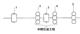
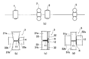
図1は、本発明に係る圧延設備列の一例を示し、図において1は粗造形圧延機、2は第1の粗ユニバーサル圧延機、3はエッジャ圧延機、4は第2の粗ユニバーサル圧延機、5は仕上圧延機を示す。
FIG. 1 shows an example of a rolling equipment line according to the present invention, in which 1 is a rough shaping rolling mill, 2 is a first rough universal rolling mill, 3 is an edger rolling mill, and 4 is a second rough universal rolling mill.
加熱炉(図示せず)から搬出された素材鋼片(図示せず)は粗造形圧延機1によって断面形状が略T形のT形鋼片に圧延される。粗造形圧延機1としては、公知の設備が利用でき、例えば、孔型を有するロールが装備された二重式圧延機とする。 A raw steel slab (not shown) carried out of a heating furnace (not shown) is rolled into a T-shaped steel slab having a substantially T-shaped cross section by the rough shaping rolling mill 1. As the rough shaping rolling mill 1, known equipment can be used, for example, a double rolling mill equipped with a roll having a hole shape.
得られたT形鋼片を、第1の粗ユニバーサル圧延機2とエッジャ圧延機3と第2の粗ユニバーサル圧延機4が近接して配置された圧延設備列で圧延を行って、ウェブとフランジの圧下を行う(中間圧延工程)。
The obtained T-shaped slab is rolled in a rolling equipment row in which the first rough
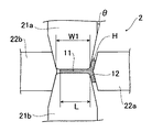
図2に第1の粗ユニバーサル圧延機2の構造を説明する模式図を示す。第1の粗ユニバーサル圧延機2は、水平軸上を回転する水平ロール21a,21bと、垂直軸上を回転する竪ロール22a,22bを有する。水平ロール21aと21b、竪ロール22aと22bは、夫々対向配置される。
FIG. 2 is a schematic diagram for explaining the structure of the first rough
本発明では、水平ロール21a、21bの圧下面の幅W1を、ウェブ11の内法寸法L(フランジ内面からウェブ先端部までの距離)より大きくする。好ましくは、ウェブ11の内法寸法Lの105〜150%程度とする。
In the present invention, the width W1 of the pressing surface of the
第1の粗ユニバーサル圧延機2では、水平ロール21a,21bによりウェブ11の高さ方向の全面をその板厚方向に圧下し、竪ロール22aと、水平ロール21a,21bの側面でフランジ12をその板厚方向に圧下する。
In the first rough
ウェブ11の板厚調整は、水平ロール21a,21bの開度調整で行い、フランジ12の板厚調整は、竪ロール22aと、水平ロール21a,21bの側面との開度調整で行う。
The thickness of the
フランジ12を圧下する際、竪ロール22aにより、水平ロール21a,21bの一方の側面から軸方向にスラスト力が作用するので、竪ロール22bを水平ロール21a,21bの、他方の側面に押圧して、水平ロール21a,21bが軸方向に移動しないようにすることが好ましい。
When the
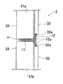
図3にエッジャ圧延機3の構造を説明する模式図を示す。エッジャ圧延機3は、水平軸方向に大径ロール部33と小径ロール部32を備えた水平ロール31a,31bを有し、大径ロール部33が被圧延材Hのウェブ11を誘導し、小径ロール部32のロール表面32aがフランジ12の端面12aをその幅方向に圧下する。
FIG. 3 is a schematic diagram for explaining the structure of the edger rolling mill 3. The edger rolling mill 3 has
大径ロール部33のロール径と、小径ロール部32のロール径は、小径ロール部32によるフランジ12の端面12aの圧延中に、大径ロール部33のロール表面がウェブ11の板厚方向の上下面に若干の隙間を有するように調整するのが好ましい。若干の隙間を設けることで、大径ロール部33がウェブに接触した場合に発生する余分な圧延反力をなくすとともに、大径ロール部33がガイドとして働き、上下のウェブ面から上下のフランジ先端までの長さを揃える効果が生まれ、寸法精度を向上させることができる。隙間は2mm以下とすることが好ましい。
The roll diameter of the large
図4に第2の粗ユニバーサル圧延機4の構造を説明する模式図を示す。第2の粗ユニバーサル圧延機4は、水平軸上を回転する水平ロール41a,41bと、垂直軸上を回転する竪ロール42a,42bを有する。水平ロール41aと41b、竪ロール42aと42bは、夫々対向配置される。
FIG. 4 is a schematic diagram illustrating the structure of the second rough universal rolling mill 4. The second rough universal rolling mill 4 has
本発明では、水平ロール41a、41bのロール面の幅W2を、ウェブ11の内法寸法L(フランジ内面からウェブ先端部11aまでの距離)より小さくする(すなわちW2<W1でもある)。好ましくは、ウェブ11の内法寸法Lの70〜95%程度とする。さらに、W1とW2との差は30mm以上確保することが好ましい。被圧延材Hのフランジ12を水平ロール41a、41bの側面に押し付けた場合、ウェブ先端部11aは、水平ロール41a、41bのロール面より外側に突出するので、竪ロール42bでウェブ11をその高さ方向に圧下することが可能となる。
In the present invention, the width W2 of the roll surface of the
第2の粗ユニバーサル圧延機4では、水平ロール41a,41bのロール開度を調整して、ウェブ11の板厚を調整し、竪ロール42aと水平ロール41a,41bの一方の側面との開度を調整することによりフランジ12の板厚を調整し、竪ロール42bと水平ロール41a,41bの他方の側面との開度を調整することによりウェブ11の高さと、端部の形状を調整する。
In the 2nd rough universal rolling mill 4, the roll opening degree of the
なお、図4のロール形状では水平ロール41a、41bの軸方向移動をウェブ先端側の竪ロール42bで抑えることができないため、水平ロール41a、41bのロール軸に水平方向の移動を抑える機構を組み込む必要がある。例えば、ロール軸にスラスト玉軸受やスラストころ軸受を組込み、軸方向のスラスト荷重を受ける構造とすればよい。
In the roll shape of FIG. 4, since the axial movement of the
また、第2の粗ユニバーサル圧延機4で被圧延材Hのフランジ12を圧延する際の圧延荷重が大きくなると、水平ロール41a、41bのロール軸に加わる水平方向の荷重も大きくなり、水平ロール41a、41bの水平方向の移動を抑える機構が大規模なものとなって設備費が過大になる場合がある。
Moreover, if the rolling load at the time of rolling the
この問題を解消するためには、図5(a)に示すように、第2の粗ユニバーサル圧延機4において、ウェブ先端部側の竪ロール42bの高さ方向中央部に溝部43を設けることが好ましい。すなわち、溝部43以外の竪ロール外周を水平ロール41a、41bの側面に接触させる構造にすれば、特別な機構を設けることなく水平ロール41a、41bの軸方向移動を抑えることができる。
In order to solve this problem, as shown in FIG. 5 (a), in the second rough universal rolling mill 4, a
溝部43は底部が垂直な直線状とし、その幅aは被圧延材Hのウェブ厚よりも大きくする。また、溝部43の深さは製品となるT形鋼のウェブ高さと水平ロールのロール面の幅W2に合わせて決定する。このときの水平ロール41a、41bの形状は、図5(a)に示すようにウェブ先端に近い側面が垂直であってもよく、また図5(b)に示すようにウェブ先端に近い側面がフランジ側の側面と同様に傾斜を有していてもよい。傾斜を有する場合には、その傾斜角度に合わせて竪ロール42bの外周にも同じ角度の傾斜を設けることが好ましい。
The
第2の粗ユニバーサル圧延機4を用いて、竪ロール42bによりウェブ11の端面をウェブの高さ方向に圧延する本発明の方法では、水平ロール41a,41bでウェブの大部分(すなわち先端部11a近傍以外)はウェブの板厚方向に圧延されているので、竪ロール42bでウェブ先端部11aを強く圧下してもウェブ11は座屈しない。
In the method of the present invention in which the second rough universal rolling mill 4 is used to roll the end surface of the
但し、水平ロール41a、41bの幅が狭いと、ウェブの非圧下部分が長くなり、座屈が生じ易くなるので、ロール面の幅は少なくとも、ウェブ内法寸法の70%とすることが好ましい。他方、ウェブ端面の圧下代を十分に確保するためには、ウェブの端部近傍20mm以上を非圧下領域とすることが好ましい。
However, if the width of the
上述した第1の粗ユニバーサル圧延機2、エッジャ圧延機3、および第2の粗ユニバーサル圧延機4による中間圧延工程においては、仕上圧延が可能な形状が得られるまで、必要に応じて往復圧延を行う。
In the intermediate rolling process by the first rough
また、第2の粗ユニバーサル圧延機4で、ウェブ11を板厚方向に圧延すると、水平ロール41a,41bにより圧下される部分と圧下されない部分(ウェブ先端部11a近傍)で、板厚差が生じることがある。
Further, when the
当該板厚差が仕上圧延機5による仕上圧延で解消されない程度に大きい場合は、被圧延材Hを逆送して、再度第1の粗ユニバーサル圧延機2で圧延して、ウェブの高さ方向の全面を圧下して解消すればよい。
When the plate thickness difference is so large that it cannot be eliminated by finish rolling by the
当該板厚差が仕上圧延機5による仕上圧延で解消される程度の大きさの場合は、中間圧延工程を終了し、仕上圧延工程を開始する。中間圧延工程の最後の圧延パスで第2の粗ユニバーサル圧延機4のロール開度を被圧延材Hの寸法よりも大きくしておき、圧延せずに通過させてもよく、この場合にはウェブ先端近傍に板厚差は発生しない。
If the plate thickness difference is such that it can be eliminated by finish rolling by the
尚、中間圧延工程では、被圧延材を圧延方向からみた断面視で、フランジとウェブとの交差角を95〜100°とすることが好ましい。当該交差角とすることで、水平ロールと被圧延のフランジ内面が圧延後、速やかにはなれて、フランジ内面に疵が発生することが防止される。また、ロール磨耗時のロール改削量を小さくでき、ロール寿命が延長される。 In the intermediate rolling step, it is preferable that the crossing angle between the flange and the web is 95 to 100 ° in a cross-sectional view of the material to be rolled as viewed from the rolling direction. By setting the crossing angle, it is possible to prevent the horizontal roll and the inner surface of the flange to be rolled from coming off quickly after rolling and generating wrinkles on the inner surface of the flange. In addition, the amount of roll refurbishment during roll wear can be reduced, and the roll life can be extended.
フランジとウェブの交差角を95〜100°とする場合は、粗ユニバーサル圧延機において、水平ロールの側面および竪ロールの圧下面を、鉛直方向から角度θ:5〜10°となるよう傾ける(図2)。竪ロールは、断面形状においてロール面の幅方向中心を頂点とする、鉛直から角度θ:5〜10°傾いた斜辺を有する上下対称の山形形状とする(図2、図4、図5)。フランジを圧下しない側の、水平ロール側面および竪ロールは、実質的にθ=0°であっても良い(図4、図5(a))。 When the crossing angle between the flange and the web is 95 to 100 °, in the rough universal rolling mill, the side surface of the horizontal roll and the pressed surface of the roll are inclined so that the angle θ is 5 to 10 ° from the vertical direction (see FIG. 2). The scissors roll has a vertically symmetrical chevron shape having a hypotenuse inclined at an angle θ of 5 to 10 ° from the vertical with the center in the width direction of the roll surface in the cross-sectional shape (FIGS. 2, 4, and 5). The side of the horizontal roll and the side roll on the side where the flange is not crushed may be substantially θ = 0 ° (FIGS. 4 and 5A).
本発明では、中間圧延工程を第1と第2の粗ユニバーサル圧延機で実施するため、一基の粗ユニバーサル圧延機で圧延する場合と比較して、1パス当たりのウェブ厚とフランジ厚の圧下量を大きくすることが可能で、圧延パスを削減し、圧延能率が向上する。 In the present invention, since the intermediate rolling process is performed by the first and second rough universal rolling mills, the web thickness and the flange thickness per pass are reduced as compared with the case of rolling by one rough universal rolling mill. The amount can be increased, reducing the rolling pass and improving the rolling efficiency.
更に圧延能率を向上させる場合は、第1の粗ユニバーサル圧延機、エッジャ圧延機、第2の粗ユニバーサル圧延機の少なくともいずれかを、複数基配置すると良い。 In order to further improve the rolling efficiency, a plurality of at least one of the first rough universal rolling mill, the edger rolling mill, and the second rough universal rolling mill may be arranged.
例えば、図7、8に示すように、第1の粗ユニバーサル圧延機2、エッジャ圧延機3および第2の粗ユニバーサル圧延機4からなる構成を複数組配置することができる。図7は、第1の粗ユニバーサル圧延機2、エッジャ圧延機3および第2の粗ユニバーサル圧延機4からなる構成を2組配置した構成である。また、図8は、第1の粗ユニバーサル圧延機2、エッジャ圧延機3および第2の粗ユニバーサル圧延機4からなる構成を3組配置した構成で、中間圧延工程を1パスで終了させることが可能であり、飛躍的に圧延能率が向上する。
For example, as shown in FIGS. 7 and 8, a plurality of sets of configurations including the first rough
なお、本発明は、図1、7、8に示す配置に限られるものではなく、第1の粗ユニバーサル圧延機2、エッジャ圧延機3および第2の粗ユニバーサル圧延機4を1基以上ずつ有する設備であれば、他のどのような配置であっても適用することができる。
The present invention is not limited to the arrangement shown in FIGS. 1, 7, and 8, and has at least one first rough
例えば、第1の粗ユニバーサル圧延機、エッジャ圧延機、第2の粗ユニバーサル圧延機の少なくともいずれかを、2基以上連続して配置してもよい。 For example, at least one of the first rough universal rolling mill, the edger rolling mill, and the second rough universal rolling mill may be continuously arranged.
また、第1の粗ユニバーサル圧延機、エッジャ圧延機、第2の粗ユニバーサル圧延機の配置順を変更して、例えば、中間圧延工程の最初にエッジャ圧延機や第2の粗ユニバーサル圧延機を配置してもよい。さらに、各圧延機は通常、リバース圧延や素通し(圧延を行わずに圧延機を通過させる)が可能なので、圧延の順番は圧延機の順番と一致せずともよい。 Further, the arrangement order of the first rough universal rolling mill, the edger rolling mill, and the second rough universal rolling mill is changed, for example, the edger rolling mill and the second rough universal rolling mill are arranged at the beginning of the intermediate rolling process. May be. Furthermore, since each rolling mill is normally capable of reverse rolling or through (passing the rolling mill without rolling), the rolling order does not have to coincide with the rolling mill order.
中間圧延工程で得られたT形鋼は、仕上圧延工程で製品寸法に圧延する。 The T-shaped steel obtained in the intermediate rolling process is rolled to the product dimensions in the finish rolling process.
図6に、仕上ユニバーサル圧延機の構造を説明する模式図を示す。仕上ユニバーサル圧延機5は、水平軸上を回転する水平ロール51a,51bと垂直軸上を回転する竪ロール52a,52bを有し、水平ロール51a,51bの側面はロール面と直交させる。
In FIG. 6, the schematic diagram explaining the structure of a finishing universal rolling mill is shown. The finishing
竪ロール52aで被圧延材Hのフランジを圧延すると、ウェブに対し、フランジが垂直に整形される。竪ロール52bを水平ロール51a,52bのフランジと対向しない側の側面に押圧することで水平ロール51a,52bが軸方向に移動しないようにできる。
When the flange of the material to be rolled H is rolled with the
仕上ユニバーサル圧延機では、ウェブはほとんど圧下されないか、または、形・寸法を整える程度に軽圧下される。この目的に適うため、水平ロール51a,51bの圧下面の幅は、ウェブ内法寸法より大きくする(したがってW2より大きい)。好ましくは、ウェブ11の内法寸法Lの105〜150%程度とする。
In the finishing universal rolling mill, the web is hardly reduced, or lightly reduced to adjust the shape and dimensions. In order to meet this purpose, the width of the pressed surface of the
仕上ユニバーサル圧延機と粗ユニバーサル圧延機は、一般にフランジ側の竪ロールの形状が異なる。すなわち、粗ユニバーサル圧延機においては、θ:3〜15°の山形形状とすることが多い。これに対して、仕上ユニバーサル圧延機においては実質的にθ=0°である。いずれのユニバーサル圧延機においても、水平ロールの圧延面は、中心軸を含む断面上で実質的に直線とする。 The finishing universal rolling mill and the rough universal rolling mill are generally different in the shape of the flange roll. That is, in a rough universal rolling mill, it is often a mountain shape with θ: 3 to 15 °. On the other hand, in the finishing universal rolling mill, θ = 0 ° substantially. In any universal rolling mill, the rolling surface of the horizontal roll is substantially straight on the cross section including the central axis.
図1に示す圧延設備を用いて、厚さ250mm、幅310mmの長方形断面を有するブルームから、ウェブ高さ300mm、フランジ幅100mm、ウェブ厚9mm、フランジ厚16mmを目標寸法とするT形鋼を圧延した。 Using the rolling equipment shown in FIG. 1, a T-section steel having a target dimension of a web height of 300 mm, a flange width of 100 mm, a web thickness of 9 mm, and a flange thickness of 16 mm is rolled from a bloom having a rectangular cross section with a thickness of 250 mm and a width of 310 mm. did.
第1の粗ユニバーサル圧延機2は、図2に示す構造のものを用いた。水平ロールは、圧下面の幅W1がウェブ内法寸法よりも広くなるように320mmとし、水平ロールの側面の鉛直方向からの角度θは、7°とした。
The 1st rough
左右の竪ロールは対向するように配置し、断面形状においてロール面の幅方向中心を頂点とする、鉛直から角度7°傾いた斜辺を有する上下対称の山形形状とした。 The left and right scissors rolls are arranged so as to be opposed to each other, and in the cross-sectional shape, a vertically symmetrical mountain shape having a hypotenuse inclined at an angle of 7 ° from the vertical with the center in the width direction of the roll surface as a vertex.
また、左右の竪ロールのうち、水平ロールの側面を押圧するものは、フランジの圧延で水平ロールが水平軸方向に移動しないように、押圧力を調整した。 In addition, among the left and right scissors rolls, the pressing force of the one that presses the side surface of the horizontal roll was adjusted so that the horizontal roll would not move in the horizontal axis direction by rolling the flange.
第2の粗ユニバーサル圧延機4は、図4に示す構造のものを用いた。水平ロールのロール軸にはスラストころ軸受を組込み、ロール軸方向の荷重に強い構造とした。水平ロールは、圧下面の幅W2がウェブ内法寸法よりも狭くなるように250mmとし、水平ロールの、フランジを圧延する側の側面は鉛直から角度7°傾けた。 The 2nd rough universal rolling mill 4 used the structure shown in FIG. A thrust roller bearing is incorporated in the roll shaft of the horizontal roll to make it resistant to loads in the roll shaft direction. The horizontal roll was 250 mm so that the width W2 of the pressed surface was narrower than the in-web dimension, and the side surface of the horizontal roll on the side where the flange was rolled was tilted by 7 ° from the vertical.
また、左右の竪ロールで、フランジを圧延する一方の竪ロールは、断面形状においてロール面の幅方向中心を頂点とする、鉛直から角度7°傾いた斜辺を有する上下対称の山形形状とし、ウェブ先端部を高さ方向に圧下する他方の竪ロールは、ロール面が平坦な円筒型とした。 In addition, one of the scissors rolls that rolls the flange with the left and right scissors rolls has a vertically-symmetrical chevron shape having a hypotenuse inclined at an angle of 7 ° from the vertical with the center in the width direction of the roll surface in the cross-sectional shape. The other scissors roll that squeezes the tip in the height direction was a cylindrical shape with a flat roll surface.
エッジャ圧延機3は図3に示す構造のものを用いた。水平ロールの大径部と小径部との段差は44mmとし、ロール幅は大径部が500mm以上、小径部が200mm以上を確保した。また、段差部分の傾斜角は鉛直から角度7°とした。 The edger rolling mill 3 has a structure shown in FIG. The level difference between the large diameter part and the small diameter part of the horizontal roll was 44 mm, and the roll width was ensured to be 500 mm or more for the large diameter part and 200 mm or more for the small diameter part. Further, the inclination angle of the step portion was set to 7 ° from the vertical.
仕上ユニバーサル圧延機5は図6に示す構造のものを用いた。水平ロールの幅は320mmとした。
A finishing
最初に、上記ブルームを粗造形圧延機1(孔型ロールを組み込んだ二重式圧延機を用いた)で圧延し、略T形断面形状のT形鋼片とした。得られたT形鋼片のウェブ厚は40mm、フランジ厚は75mm、ウェブ高さ375mm、フランジ幅130mmであった。 First, the bloom was rolled with a rough shaping rolling mill 1 (using a double rolling mill incorporating a perforated roll) to obtain a T-shaped steel piece having a substantially T-shaped cross section. The obtained T-shaped billet had a web thickness of 40 mm, a flange thickness of 75 mm, a web height of 375 mm, and a flange width of 130 mm.
続いて、上述した第1粗ユニバーサル圧延機2、エッジャ圧延機3、および第2粗ユニバーサル圧延機4をこの順に近接配置した圧延機群で5パスの往復圧延を行って、ウェブとフランジを圧下した。
Subsequently, reciprocal rolling of 5 passes is performed by a rolling mill group in which the first rough
第2粗ユニバーサル圧延機4では竪ロールを用いてウェブ先端部をウェブ高さ方向に圧下し、ウェブ高さの調整を行った。最後に、水平ロールと竪ロールとを有する仕上ユニバーサル圧延機5でフランジの傾斜を鉛直に整形した。ウェブ部は軽圧下とした。
In the 2nd rough universal rolling mill 4, the web front-end | tip part was crushed in the web height direction using the roll, and the web height was adjusted. Finally, the inclination of the flange was vertically shaped by a finishing
熱間圧延後、得られたT形鋼のウェブ高さ、フランジ幅、ウェブ厚、フランジ厚を測定したところ、目標通りの寸法で、本発明によれば目標寸法を満足するT形鋼を熱間圧延ままで製造できることが確認された。 After hot rolling, the web height, flange width, web thickness, and flange thickness of the obtained T-shaped steel were measured. As a result, according to the present invention, the T-shaped steel satisfying the target dimension was heated. It was confirmed that it could be produced as it was rolled.
特に、従来圧延ままでは調整が困難であったウェブ高さは、目標値±1mmの範囲で熱間圧延することが可能で、端面形状も良好であった。 In particular, the web height, which was difficult to adjust with the conventional rolling, can be hot-rolled within the range of the target value ± 1 mm, and the end face shape was also good.
なお、第2ユニバーサル圧延機4の水平ロールの圧下面の幅W2を種々に変更する実験も行ったが、製品のウェブ内法寸法に対してW2が少なくとも70%あれば、ウェブが座屈することなく高さ方向の圧下が可能であった。 In addition, although the experiment which changes variously the width W2 of the pressing surface of the horizontal roll of the 2nd universal rolling mill 4 was also performed, if W2 is at least 70% with respect to the in-web normal dimension of the product, the web will buckle. It was possible to reduce in the height direction.
一方、比較例として、中間圧延工程を、水平ロールの圧下面幅をウェブ幅より広く設定した粗ユニバーサル圧延機を1基と、エッジャ圧延機1基とからなる従来の圧延設備(図10)を用いて実施し、T形鋼を製造した。ブルーム寸法、T形鋼の熱間圧延後の各部の目標寸法は本発明例と同じとした。比較例の設備では粗ユニバーサル圧延機が1基しかないため、パス数が9パスの往復圧延を行って目標寸法まで圧延した。 On the other hand, as a comparative example, an intermediate rolling process is performed using a conventional rolling facility (FIG. 10) composed of one rough universal rolling mill in which the width of the pressed surface of the horizontal roll is set wider than the web width and one edger rolling mill. T-shaped steel was manufactured. The bloom dimensions and the target dimensions of each part after hot rolling of the T-shaped steel were the same as those of the example of the present invention. Since there was only one rough universal rolling mill in the equipment of the comparative example, reciprocating rolling with 9 passes was performed to the target dimension.
比較例では、ウェブの先端を圧下することができなかったため、ウェブ高さが目標の300mmよりも大きくなり、306mm程度となって寸法外れが発生した。このため、圧延後にウェブの端部を切断する必要が生じ、時間と費用がかかり製造コストが増加した。 In the comparative example, since the tip of the web could not be crushed, the web height became larger than the target of 300 mm, and was about 306 mm, resulting in a dimension error. For this reason, it became necessary to cut the edge part of a web after rolling, and time and expense increased, and the manufacturing cost increased.
また、パス数が増えたため本発明の実施例に比較して中間圧延の圧延時間が2倍に増え、生産性が大幅に悪化した。 In addition, since the number of passes increased, the rolling time of intermediate rolling was doubled compared to the examples of the present invention, and the productivity was greatly deteriorated.
なお、上記実施例において、W1および仕上ユニバーサル圧延機の水平ロールの幅をそれぞれ340mmに変えてみたが、やはり結果は良好であった。 In addition, in the said Example, although the width of the horizontal roll of W1 and a finishing universal rolling mill was changed to 340 mm, respectively, the result was also favorable.
次に、本発明の第2の実施例として、図5(b)に示す水平ロールの両方の側面に傾斜を有する粗ユニバーサル圧延機を第2の粗ユニバーサル圧延機に用いて、本発明の第1の実施例と同様の寸法を有するT形鋼を圧延した。 Next, as a second embodiment of the present invention, a rough universal rolling mill having slopes on both sides of the horizontal roll shown in FIG. 5B is used for the second rough universal rolling mill. A T-shaped steel having the same dimensions as in Example 1 was rolled.
粗造形圧延機1、第1の粗ユニバーサル圧延機2およびエッジャ圧延機3は、第1の実施例と同じ設備を用いた。第2の粗ユニバーサル圧延機4の水平ロール軸受は、第1の実施例のような特別な軸受ではなく通常のものを使用したため、設備費が節約できた。
The rough shaping rolling mill 1, the first rough
水平ロールは、圧下面の幅W2がウェブ内法寸法よりも狭くなるように250mmとし、水平ロールの、フランジを圧延する側の側面は鉛直から角度7°傾けた。竪ロールは断面形状においてロール面の幅方向中心を頂点とする、鉛直から角度7°傾いた斜辺を有する上下対称の山形形状とし、ウェブ先端側の竪ロール42bには竪ロール表面からの深さ34mm、幅100mmの底部が垂直な直線状の溝部を設けた。 The horizontal roll was 250 mm so that the width W2 of the pressed surface was narrower than the in-web dimension, and the side surface of the horizontal roll on the side where the flange was rolled was tilted by 7 ° from the vertical. The scissors roll has a vertically symmetrical mountain shape with a hypotenuse inclined at an angle of 7 ° from the vertical with the center in the width direction of the roll surface in the cross-sectional shape, and the scissors roll 42b on the web tip side has a depth from the scissors roll surface. A linear groove having a vertical bottom of 34 mm and a width of 100 mm was provided.
T形鋼の製造では、まず、第1の実施例と同様の寸法を有するブルームを粗造形圧延機1で圧延し、略T形断面形状のT形鋼片とした。得られたT形鋼片の寸法は第1の実施例と同様にウェブ厚40mm、フランジ厚75mm、ウェブ高さ375mm、フランジ幅130mmであった。 In the manufacture of the T-shaped steel, first, a bloom having the same dimensions as in the first example was rolled by the rough shaping rolling mill 1 to obtain a T-shaped steel piece having a substantially T-shaped cross section. The dimensions of the obtained T-shaped slab were a web thickness of 40 mm, a flange thickness of 75 mm, a web height of 375 mm, and a flange width of 130 mm, as in the first example.
続いて、第1粗ユニバーサル圧延機2、エッジャ圧延機3、および第2粗ユニバーサル圧延機4をこの順に近接配置した圧延機群で5パスの往復圧延を行って、ウェブとフランジを圧下した。
Subsequently, reciprocal rolling of 5 passes was performed by a rolling mill group in which the first rough
第2粗ユニバーサル圧延機4ではウェブ先端側の竪ロールを水平ロール側面に押付けた状態で圧延し、ウェブ先端部をウェブ高さ方向に圧下してウェブ高さの調整を行った。最後に、水平ロールと竪ロールとを有する仕上ユニバーサル圧延機5でフランジの傾斜を鉛直に整形した。
In the second rough universal rolling mill 4, rolling was performed in a state where the roll on the web tip side was pressed against the side surface of the horizontal roll, and the web tip was adjusted in the web height direction to adjust the web height. Finally, the inclination of the flange was vertically shaped by a finishing
熱間圧延後、得られたT形鋼のウェブ高さ、フランジ幅、ウェブ厚、フランジ厚を測定したところ、目標通りの寸法になっており、ウェブ高さは目標値±1mmの範囲で、端面形状も良好であった。以上の結果から、本発明の図5(b)に示す第2の粗ユニバーサル圧延機を用いたT形鋼の製造方法と圧延設備で、寸法精度の良好なT形鋼を熱間圧延ままで製造できることが確認できた。 After hot rolling, when the web height, flange width, web thickness and flange thickness of the obtained T-shaped steel were measured, the dimensions were as intended, and the web height was within the target value ± 1 mm. The end face shape was also good. From the above results, the T-shaped steel with a good dimensional accuracy is still hot-rolled with the T-shaped steel manufacturing method and rolling equipment using the second rough universal rolling mill shown in FIG. 5 (b) of the present invention. It was confirmed that it could be manufactured.
次に、本発明の第3の実施例として、図1に示す圧延設備において、第1の粗ユニバーサル圧延機2と第2の粗ユニバーサル圧延機4とを入れ替えた圧延設備列を用いて、厚さ300mm、幅620mmの長方形断面を有するブルームから、ウェブ高さ500mm、フランジ幅150mm、ウェブ厚12mm、フランジ厚22mmを目標寸法とするT形鋼を圧延した。
Next, as a third embodiment of the present invention, in the rolling equipment shown in FIG. 1, a thickness of the rolling equipment row in which the first rough
すなわち、第3の実施例における中間圧延工程では、第2の粗ユニバーサル圧延機4、エッジャ圧延機3、第1の粗ユニバーサル圧延機2が、この順序で配置されている。
That is, in the intermediate rolling process in the third embodiment, the second rough universal rolling mill 4, the edger rolling mill 3, and the first rough
第2の粗ユニバーサル圧延機4は、図5(b)に示す水平ロールの両方の側面に傾斜を有する構造のものを用いた。水平ロールは、圧下面の幅W2がウェブ内法寸法よりも狭くなるように440mmとし、水平ロールの側面は鉛直から角度7°傾けた。 The 2nd rough universal rolling mill 4 used the structure which has an inclination in the both sides | surfaces of the horizontal roll shown in FIG.5 (b). The horizontal roll was 440 mm so that the width W2 of the pressed surface was narrower than the in-web dimension, and the side surface of the horizontal roll was tilted by 7 ° from the vertical.
竪ロールは断面形状においてロール面の幅方向中心を頂点とする、鉛直から角度7°傾いた斜辺を有する上下対称の山形形状とし、ウェブ先端側の竪ロール42bには竪ロール表面からの深さ37mm、幅100mmの底部が垂直な直線状の溝部を設けた。 The scissors roll has a vertically symmetrical mountain shape with a hypotenuse inclined at an angle of 7 ° from the vertical with the center in the width direction of the roll surface in the cross-sectional shape, and the scissors roll 42b on the web tip side has a depth from the scissors roll surface. A linear groove having a bottom of 37 mm and a width of 100 mm was provided.
エッジャ圧延機3は図3に示す構造のものを用いた。水平ロールの大径部と小径部との段差は68mmとし、ロール幅は大径部が550mm以上、小径部が200mm以上を確保した。また、段差部分の傾斜角は鉛直から角度7°とした。 The edger rolling mill 3 has a structure shown in FIG. The level difference between the large diameter part and the small diameter part of the horizontal roll was 68 mm, and the roll width was 550 mm or more for the large diameter part and 200 mm or more for the small diameter part. Further, the inclination angle of the step portion was set to 7 ° from the vertical.
第1の粗ユニバーサル圧延機2は、図2に示す構造のものを用いた。水平ロールは、圧下面の幅W1がウェブ内法寸法よりも広くなるように530mmとし、水平ロールの側面の鉛直方向からの角度θは、7°とした。
The 1st rough
左右の竪ロールは対向するように配置し、断面形状においてロール面の幅方向中心を頂点とする、鉛直から角度7°傾いた斜辺を有する上下対称の山形形状とした。また、左右の竪ロールのうち、水平ロールの側面を押圧するものは、フランジの圧延で水平ロールが水平軸方向に移動しないように、押圧力を調整した。 The left and right scissors rolls are arranged so as to be opposed to each other, and in the cross-sectional shape, a vertically symmetrical mountain shape having a hypotenuse inclined at an angle of 7 ° from the vertical with the center in the width direction of the roll surface as a vertex. In addition, among the left and right scissors rolls, the pressing force of the one that presses the side surface of the horizontal roll was adjusted so that the horizontal roll would not move in the horizontal axis direction by rolling the flange.
仕上ユニバーサル圧延機5は図6に示す構造のものを用いた。水平ロールの幅は520mmとした。
A finishing
最初に、上記ブルームを粗造形圧延機1(孔型ロールを組み込んだ二重式圧延機を用いた)で圧延し、略T形断面形状のT形鋼片とした。得られたT形鋼片のウェブ厚は50mm、フランジ厚は95mm、ウェブ高さ585mm、フランジ幅185mmであった。 First, the bloom was rolled with a rough shaping rolling mill 1 (using a double rolling mill incorporating a perforated roll) to obtain a T-shaped steel piece having a substantially T-shaped cross section. The obtained T-shaped billet had a web thickness of 50 mm, a flange thickness of 95 mm, a web height of 585 mm, and a flange width of 185 mm.
続いて、上述した第2粗ユニバーサル圧延機4、エッジャ圧延機3、および第1粗ユニバーサル圧延機2をこの順に近接配置した圧延機群で5パスの往復圧延を行って、ウェブとフランジを圧下した。
Subsequently, the second coarse universal rolling mill 4, the edger rolling mill 3, and the first coarse
第2粗ユニバーサル圧延機4ではウェブ先端側の竪ロールを水平ロール側面に押付けた状態で圧延し、ウェブ先端部をウェブ高さ方向に圧下してウェブ高さの調整を行った。最後に、水平ロールと竪ロールとを有する仕上ユニバーサル圧延機5でフランジの傾斜を鉛直に整形した。
In the second rough universal rolling mill 4, rolling was performed in a state where the roll at the web tip side was pressed against the side surface of the horizontal roll, and the web height was adjusted by reducing the web tip portion in the web height direction. Finally, the inclination of the flange was shaped vertically by a finishing
熱間圧延後、得られたT形鋼のウェブ高さ、フランジ幅、ウェブ厚、フランジ厚を測定したところ、目標通りの寸法になっており、ウェブ高さは目標値±1mmの範囲で、端面形状も良好であった。 After hot rolling, when the web height, flange width, web thickness and flange thickness of the obtained T-shaped steel were measured, the dimensions were as intended, and the web height was within the target value ± 1 mm. The end face shape was also good.
以上の結果から、本発明のT形鋼の製造方法と圧延設備で、ウェブ高さ500mm、フランジ幅150mmといった大きなサイズのT形鋼であっても、寸法精度の良好なT形鋼を熱間圧延ままで製造できることが確認できた。 From the above results, the T-shaped steel of the present invention can be hot-rolled with a T-shaped steel having a good dimensional accuracy even with a large-sized T-shaped steel having a web height of 500 mm and a flange width of 150 mm. It was confirmed that the product could be produced as it was rolled.
1 粗造形圧延機
2 第1の粗ユニバーサル圧延機
3 エッジャ圧延機
4 第2の粗ユニバーサル圧延機
5 仕上ユニバーサル圧延機
11 ウェブ
11a ウェブの端面(ウェブ先端部)
12 フランジ
12a フランジの端面
21a,21b 水平ロール
22a,22b 竪ロール
31a,31b エッジャロール
32 小径部
32a 圧下面
33 大径部
41a,41b 水平ロール
42a,42b 竪ロール
43 溝部
51a,51b 水平ロール
52a,52b 竪ロール
W1 第1の粗ユニバーサル圧延機の水平ロールの圧下面の幅
W2 第2の粗ユニバーサル圧延機の水平ロールの圧下面の幅
L ウェブ内法寸法
H 被圧延材
DESCRIPTION OF SYMBOLS 1 Rough
12
Claims (3)
前記中間圧延工程は、上下の水平ロールがウェブの板厚方向における上下面の全面を圧下する第1の粗ユニバーサル圧延機による圧延工程と、フランジの端面を圧下するエッジャ圧延工程と、上下の水平ロールが、ウェブの端部近傍を除いた板厚方向の上下面を圧下しつつ、左右の竪ロールの一方がウェブの端面をウェブの高さ方向に圧下し、他方がフランジをその板厚方向に圧下する第2の粗ユニバーサル圧延機による圧延工程とを有し、前記仕上圧延工程は仕上ユニバーサル圧延機による圧延工程を有することを特徴とするT形鋼の製造方法。 An intermediate rolling step of rolling a web and a flange of a T-shaped steel piece roughly formed into a T-shape, and a finishing rolling step of performing a finish rolling to make the T-shaped steel piece obtained in the intermediate rolling step into a product shape A method for producing a T-shaped steel having
The intermediate rolling process includes a rolling process by a first rough universal rolling mill in which upper and lower horizontal rolls roll down the entire upper and lower surfaces in the web thickness direction, an edger rolling process in which the end face of the flange is rolled down, and upper and lower horizontal rolls. While the roll is rolling down the upper and lower surfaces in the plate thickness direction excluding the vicinity of the end of the web, one of the left and right heel rolls rolls down the web end surface in the web height direction, and the other is the flange second and a rolling step using rough universal rolling mill, the finishing rolling step the method for producing a T-shaped steel, characterized by have a rolling process by the finishing universal rolling machine for rolling the.
中間圧延工程として、ロール面の幅が前記被圧延材のウェブ内法寸法より広い上下の水平ロールを有する第1の粗ユニバーサル圧延機と、前記被圧延材のフランジの端面を圧下するエッジャ圧延機と、ロール面の幅が前記被圧延材のウェブ内法寸法より狭い上下の水平ロールおよび一方がフランジをその板厚方向に圧下し他方がウェブの端面をウェブの高さ方向に圧下する左右の竪ロールを有する第2の粗ユニバーサル圧延機とが配置されてなり、
仕上圧延工程として、ロール面の幅が前記被圧延材のウェブ内法寸法より広い上下の水平ロールを有する仕上ユニバーサル圧延機が配置されてなることを特徴とするT形鋼の圧延設備列。 A T-shaped steel rolling equipment row for rolling a web and a flange using a T-shaped steel piece roughly formed into a T-shape as a material to be rolled,
As an intermediate rolling step, a first rough universal rolling mill having upper and lower horizontal rolls whose roll surface width is wider than the in-web dimension of the material to be rolled, and an edger rolling machine for rolling down the end face of the flange of the material to be rolled Upper and lower horizontal rolls whose width of the roll surface is narrower than the in-web dimension of the material to be rolled, and one that reduces the flange in the plate thickness direction and the other that reduces the end surface of the web in the web height direction. a second coarse universal rolling machine are arranged with vertical rolls with Ri Na,
As the finish rolling step, rolling equipment rows of T shaped steel width of the roll surface is characterized Rukoto finish universal rolling mill, such are arranged with a wider upper and lower horizontal rolls from web in dimensions, of the material to be rolled.
Priority Applications (5)
| Application Number | Priority Date | Filing Date | Title |
|---|---|---|---|
| JP2008132900A JP4453771B2 (en) | 2007-05-31 | 2008-05-21 | T-section steel manufacturing method and rolling equipment line |
| PCT/JP2008/060324 WO2008146948A1 (en) | 2007-05-31 | 2008-05-29 | Process for manufacturing t-shaped steel and rolling equipment line |
| KR1020107007821A KR101084617B1 (en) | 2007-05-31 | 2008-05-29 | Rolling equipment line for t-shaped steel |
| CN2008800181739A CN101678413B (en) | 2007-05-31 | 2008-05-29 | Process for manufacturing T-shaped steel and rolling equipment line |
| KR1020097024541A KR100975818B1 (en) | 2007-05-31 | 2008-05-29 | Process for manufacturing t-shaped steel and rolling equipment line |
Applications Claiming Priority (2)
| Application Number | Priority Date | Filing Date | Title |
|---|---|---|---|
| JP2007144288 | 2007-05-31 | ||
| JP2008132900A JP4453771B2 (en) | 2007-05-31 | 2008-05-21 | T-section steel manufacturing method and rolling equipment line |
Publications (3)
| Publication Number | Publication Date |
|---|---|
| JP2009006397A JP2009006397A (en) | 2009-01-15 |
| JP2009006397A5 JP2009006397A5 (en) | 2010-01-28 |
| JP4453771B2 true JP4453771B2 (en) | 2010-04-21 |
Family
ID=40322031
Family Applications (1)
| Application Number | Title | Priority Date | Filing Date |
|---|---|---|---|
| JP2008132900A Active JP4453771B2 (en) | 2007-05-31 | 2008-05-21 | T-section steel manufacturing method and rolling equipment line |
Country Status (4)
| Country | Link |
|---|---|
| JP (1) | JP4453771B2 (en) |
| KR (2) | KR101084617B1 (en) |
| CN (1) | CN101678413B (en) |
| WO (1) | WO2008146948A1 (en) |
Cited By (1)
| Publication number | Priority date | Publication date | Assignee | Title |
|---|---|---|---|---|
| JP2012096287A (en) * | 2010-10-06 | 2012-05-24 | Jfe Steel Corp | Vertical roll of universal rolling mill, the universal rolling mill, and method for manufacturing t-shaped steel |
Families Citing this family (9)
| Publication number | Priority date | Publication date | Assignee | Title |
|---|---|---|---|---|
| JP4544371B2 (en) | 2008-11-20 | 2010-09-15 | Jfeスチール株式会社 | T-section steel manufacturing method and rolling equipment line |
| JP5621243B2 (en) * | 2009-11-10 | 2014-11-12 | Jfeスチール株式会社 | T-shaped steel rolling equipment |
| CN101862750B (en) * | 2010-05-28 | 2012-02-01 | 沈阳和世泰通用钛业有限公司 | Method for producing titanium or titanium alloy T sections |
| CN102247981B (en) * | 2011-06-01 | 2013-06-26 | 中冶赛迪工程技术股份有限公司 | Structural steel rolling production line and production process thereof |
| CN104053512B (en) * | 2012-01-17 | 2015-12-09 | 杰富意钢铁株式会社 | The manufacture method of T-steel and rolling equipment |
| CN102794298A (en) * | 2012-08-16 | 2012-11-28 | 中冶赛迪工程技术股份有限公司 | Process and device for rolling H-shaped steel |
| KR101659743B1 (en) * | 2014-11-18 | 2016-09-26 | 정승돈 | Steel i-bar manufacturing method |
| IT201700105530A1 (en) * | 2017-09-21 | 2019-03-21 | Corimpex S R L | WELDING, PLANT AND WELDING PROCEDURE |
| CN109719126B (en) * | 2019-02-28 | 2021-01-08 | 武汉钢铁有限公司 | Rolling process of F-shaped rail rolling pass system |
Family Cites Families (5)
| Publication number | Priority date | Publication date | Assignee | Title |
|---|---|---|---|---|
| JPS6011563B2 (en) | 1980-06-11 | 1985-03-27 | 日本鋼管株式会社 | How to roll T-shaped steel |
| JPH08215702A (en) | 1995-02-16 | 1996-08-27 | Nippon Steel Corp | Rolling method of shape having flange and web and rolling device train |
| JP2002301501A (en) | 2001-04-06 | 2002-10-15 | Yamato Kogyo Co Ltd | T section and method for manufacturing the same |
| JP2007331027A (en) * | 2005-11-15 | 2007-12-27 | Sumitomo Metal Ind Ltd | Method of manufacturing hot-rolled t-shape steel for hull reinforcing member and hot-rolled t-shape steel |
| CN100431731C (en) * | 2006-03-08 | 2008-11-12 | 中国新兴建设开发总公司 | Mechanical corrector for T-shape steel member bending deformation |
-
2008
- 2008-05-21 JP JP2008132900A patent/JP4453771B2/en active Active
- 2008-05-29 WO PCT/JP2008/060324 patent/WO2008146948A1/en active Application Filing
- 2008-05-29 KR KR1020107007821A patent/KR101084617B1/en not_active IP Right Cessation
- 2008-05-29 CN CN2008800181739A patent/CN101678413B/en active Active
- 2008-05-29 KR KR1020097024541A patent/KR100975818B1/en active IP Right Grant
Cited By (1)
| Publication number | Priority date | Publication date | Assignee | Title |
|---|---|---|---|---|
| JP2012096287A (en) * | 2010-10-06 | 2012-05-24 | Jfe Steel Corp | Vertical roll of universal rolling mill, the universal rolling mill, and method for manufacturing t-shaped steel |
Also Published As
| Publication number | Publication date |
|---|---|
| KR20100054854A (en) | 2010-05-25 |
| KR20090130330A (en) | 2009-12-22 |
| CN101678413A (en) | 2010-03-24 |
| JP2009006397A (en) | 2009-01-15 |
| CN101678413B (en) | 2012-03-21 |
| WO2008146948A1 (en) | 2008-12-04 |
| KR101084617B1 (en) | 2011-11-17 |
| KR100975818B1 (en) | 2010-08-13 |
Similar Documents
| Publication | Publication Date | Title |
|---|---|---|
| JP4453771B2 (en) | T-section steel manufacturing method and rolling equipment line | |
| JP4544371B2 (en) | T-section steel manufacturing method and rolling equipment line | |
| JP5141839B2 (en) | T-section steel manufacturing method and rolling equipment | |
| JP7280503B2 (en) | Method for manufacturing asymmetric H-beam steel with different left and right flange thicknesses | |
| JP6417991B2 (en) | Shaped steel edger rolling mill with flange | |
| JP7280505B2 (en) | Method for manufacturing asymmetric H-beam steel with different left and right flange thicknesses | |
| JP4992040B2 (en) | T-section steel rolling method and rolling equipment | |
| JP4930384B2 (en) | H-section steel rolling method and rolling apparatus | |
| JP2943326B2 (en) | Method for manufacturing H-section steel | |
| JP3339466B2 (en) | H-section steel and its rolling method | |
| WO2013108418A1 (en) | Method for manufacturing t-shaped steel and rolling equipment | |
| JP2012071346A (en) | Method of manufacturing h-section steel and h-section steel manufacturing equipment | |
| RU2386508C2 (en) | Method for manufacturing of bent thin-wall welded section bars of channel type | |
| JP6703306B2 (en) | Method for manufacturing H-section steel | |
| JP2021098210A (en) | Manufacturing method for asymmetric h-shaped steel having left and right flange with different thickness | |
| JP2021030233A (en) | Production method for asymmetric h-steel having right-and-left flange thicknesses different from each other | |
| JP6747256B2 (en) | Method for manufacturing H-section steel | |
| JP5929542B2 (en) | Rolling method and rolling equipment for channel steel | |
| JP2021109180A (en) | Method of manufacturing h-shaped steel | |
| JP2522059B2 (en) | Method for hot rolling profile with flange | |
| JP6394408B2 (en) | Intermediate universal rolling roll of H-section steel and intermediate universal rolling mill | |
| JP2023100065A (en) | Facility and method for manufacturing hat-shaped steel sheet pile | |
| JP2023039810A (en) | Manufacturing method for hat-shaped steel sheet pile | |
| JP2015205292A (en) | Rolling apparatus for shaped steel having flange and edger rolling machine | |
| JP2508873B2 (en) | Method for hot rolling profile with flange |
Legal Events
| Date | Code | Title | Description |
|---|---|---|---|
| A521 | Request for written amendment filed |
Free format text: JAPANESE INTERMEDIATE CODE: A523 Effective date: 20091204 |
|
| A621 | Written request for application examination |
Free format text: JAPANESE INTERMEDIATE CODE: A621 Effective date: 20091204 |
|
| A871 | Explanation of circumstances concerning accelerated examination |
Free format text: JAPANESE INTERMEDIATE CODE: A871 Effective date: 20091204 |
|
| A975 | Report on accelerated examination |
Free format text: JAPANESE INTERMEDIATE CODE: A971005 Effective date: 20091225 |
|
| TRDD | Decision of grant or rejection written | ||
| A01 | Written decision to grant a patent or to grant a registration (utility model) |
Free format text: JAPANESE INTERMEDIATE CODE: A01 Effective date: 20100112 |
|
| A01 | Written decision to grant a patent or to grant a registration (utility model) |
Free format text: JAPANESE INTERMEDIATE CODE: A01 |
|
| A61 | First payment of annual fees (during grant procedure) |
Free format text: JAPANESE INTERMEDIATE CODE: A61 Effective date: 20100125 |
|
| FPAY | Renewal fee payment (event date is renewal date of database) |
Free format text: PAYMENT UNTIL: 20130212 Year of fee payment: 3 |
|
| R150 | Certificate of patent or registration of utility model |
Ref document number: 4453771 Country of ref document: JP Free format text: JAPANESE INTERMEDIATE CODE: R150 Free format text: JAPANESE INTERMEDIATE CODE: R150 |
|
| FPAY | Renewal fee payment (event date is renewal date of database) |
Free format text: PAYMENT UNTIL: 20130212 Year of fee payment: 3 |
|
| R250 | Receipt of annual fees |
Free format text: JAPANESE INTERMEDIATE CODE: R250 |
|
| R250 | Receipt of annual fees |
Free format text: JAPANESE INTERMEDIATE CODE: R250 |
|
| R250 | Receipt of annual fees |
Free format text: JAPANESE INTERMEDIATE CODE: R250 |
|
| R250 | Receipt of annual fees |
Free format text: JAPANESE INTERMEDIATE CODE: R250 |