JP4452128B2 - Radio network control method, radio network control system, and radio network control apparatus - Google Patents
Radio network control method, radio network control system, and radio network control apparatus Download PDFInfo
- Publication number
- JP4452128B2 JP4452128B2 JP2004166120A JP2004166120A JP4452128B2 JP 4452128 B2 JP4452128 B2 JP 4452128B2 JP 2004166120 A JP2004166120 A JP 2004166120A JP 2004166120 A JP2004166120 A JP 2004166120A JP 4452128 B2 JP4452128 B2 JP 4452128B2
- Authority
- JP
- Japan
- Prior art keywords
- data
- radio network
- radio
- wireless
- control device
- Prior art date
- Legal status (The legal status is an assumption and is not a legal conclusion. Google has not performed a legal analysis and makes no representation as to the accuracy of the status listed.)
- Expired - Fee Related
Links
- 238000000034 method Methods 0.000 title claims description 67
- 230000005540 biological transmission Effects 0.000 claims description 114
- 238000004891 communication Methods 0.000 claims description 74
- 230000004044 response Effects 0.000 claims description 20
- 238000006243 chemical reaction Methods 0.000 claims description 15
- 230000001360 synchronised effect Effects 0.000 claims 1
- 238000012545 processing Methods 0.000 description 17
- 230000008569 process Effects 0.000 description 12
- 230000000694 effects Effects 0.000 description 9
- 238000010586 diagram Methods 0.000 description 8
- 230000008054 signal transmission Effects 0.000 description 8
- 238000005259 measurement Methods 0.000 description 4
- 230000008859 change Effects 0.000 description 2
- 238000001514 detection method Methods 0.000 description 2
- 238000010295 mobile communication Methods 0.000 description 2
- 230000002250 progressing effect Effects 0.000 description 2
- 230000005641 tunneling Effects 0.000 description 2
- 241000948268 Meda Species 0.000 description 1
- 239000000470 constituent Substances 0.000 description 1
- 238000007796 conventional method Methods 0.000 description 1
- 230000006872 improvement Effects 0.000 description 1
- 238000012544 monitoring process Methods 0.000 description 1
- 230000011664 signaling Effects 0.000 description 1
- 230000001052 transient effect Effects 0.000 description 1
Images


Classifications
-
- H—ELECTRICITY
- H04—ELECTRIC COMMUNICATION TECHNIQUE
- H04W—WIRELESS COMMUNICATION NETWORKS
- H04W36/00—Hand-off or reselection arrangements
- H04W36/10—Reselecting an access point controller
-
- H—ELECTRICITY
- H04—ELECTRIC COMMUNICATION TECHNIQUE
- H04W—WIRELESS COMMUNICATION NETWORKS
- H04W36/00—Hand-off or reselection arrangements
- H04W36/0005—Control or signalling for completing the hand-off
- H04W36/0007—Control or signalling for completing the hand-off for multicast or broadcast services, e.g. MBMS
-
- H—ELECTRICITY
- H04—ELECTRIC COMMUNICATION TECHNIQUE
- H04W—WIRELESS COMMUNICATION NETWORKS
- H04W92/00—Interfaces specially adapted for wireless communication networks
- H04W92/04—Interfaces between hierarchically different network devices
- H04W92/14—Interfaces between hierarchically different network devices between access point controllers and backbone network device
-
- H—ELECTRICITY
- H04—ELECTRIC COMMUNICATION TECHNIQUE
- H04W—WIRELESS COMMUNICATION NETWORKS
- H04W92/00—Interfaces specially adapted for wireless communication networks
- H04W92/16—Interfaces between hierarchically similar devices
- H04W92/22—Interfaces between hierarchically similar devices between access point controllers
Landscapes
- Engineering & Computer Science (AREA)
- Computer Networks & Wireless Communication (AREA)
- Signal Processing (AREA)
- Mobile Radio Communication Systems (AREA)
- Data Exchanges In Wide-Area Networks (AREA)
Description
本発明は移動体通信システムの無線アクセス網において、例えば、マルチキャストを用いたサービスの提供中に端末がセルを移動した際に通信を継続される無線網制御装置の切替方法に関するものである。 The present invention relates to a switching method of a radio network control apparatus in which communication is continued in a radio access network of a mobile communication system, for example, when a terminal moves between cells while providing a service using multicast.
現在、携帯電話の用途が、音声に加え、WWWへのアクセスやテレビ電話など、より帯域を必要とする分野にも広がり、帯域の需要も増加している。これに対応して、W−CDMA(Wideband Code Division Multiple Access)方式やMC−CDMA(Multicarrier CDMA)方式に代表される、いわゆる第三世代方式の導入が進んでおり、更に、3GPP(3rd Generation Partnership Project)においてもマルチキャストサービスを提供するMBMS(Mobile Broadcast/Multicast Service)の規格化が進展している。 At present, the use of mobile phones is expanding to fields that require more bandwidth, such as access to WWW and videophones, in addition to voice, and the demand for bandwidth is also increasing. Corresponding to this, the introduction of so-called third generation methods represented by W-CDMA (Wideband Code Division Multiple Access) method and MC-CDMA (Multicarrier CDMA) method is progressing, and further 3GPP (3rd Generation Partnership) In the Project), standardization of MBMS (Mobile Broadcast / Multicast Service) that provides a multicast service is also progressing.
従来技術であるW−CDMA方式の無線アクセス網の構成を図7に示す。MBMSに関する仕様は3GPPにおいて、TS22.146、TS23.846、TS25.346、TS25.992に記載されている。 FIG. 7 shows the configuration of a conventional W-CDMA wireless access network. Specifications related to MBMS are described in 3GPP in TS 22.146, TS 23.846, TS 25.346, and TS 25.992.
図7において、BM−SC701(Broadcast/Multicast Service Controller)はMBMSの制御を行うサービス制御装置である。 In FIG. 7, BM-SC 701 (Broadcast / Multicast Service Controller) is a service control apparatus that controls MBMS.
GGSN702(Gateway GPRS Support Node)はGPRSパケットの中継を行うGPRS中継装置である。SGSN703(Serving GPRS Support Node)はGPRSの制御を行う。無線網中継装置708はコアネットワークと無線網制御装置704a,704b間のゲートウェイであり、SGSN703と無線網制御装置704a,704b間で中継処理を行う。GGSN702、SGSN703、無線網中継装置708、無線網制御装置704はMBMSなどのデータパケットを中継するため、これらを総称する場合は単に「データパケットの中継装置」と記述する。
A GGSN 702 (Gateway GPRS Support Node) is a GPRS relay device that relays GPRS packets. SGSN 703 (Serving GPRS Support Node) controls GPRS. The radio
第一無線網制御装置704aと第二無線網制御装置704bはそれぞれの無線アクセス網の制御を行う。以下の説明では、第一無線網制御装置704aと第二無線網制御装置704bを総称して無線網制御装置704という。また、無線網制御装置をRNCと略すこともある。第一基地局705a、第二基地局705bは有線の無線アクセス網の信号と無線データの変換を行い、送受信する基地局である。以下の説明では、第一基地局705aと第二基地局705bを総称して基地局705という。端末706は無線通信を行う。セルA、セルBはそれぞれ第一基地局705aと第二基地局705bの信号が届き、端末706と通信できる範囲を示す。
The first
MBMSは、BM−SC701に他のIP網からコンテンツプロバイダ等によって入力されたパケットをGGSN702、SGSN703、無線アクセス網を経由し、片方向で端末まで伝送させるサービスである。コアネットワークまたは無線アクセス網内に流れるトラフィックを削減するために、RA(Routing Area)となっていないSGSN703から無線網制御装置704にはパケットを伝送しない。 MBMS is a service that allows a BM-SC 701 to transmit a packet input from another IP network by a content provider or the like to a terminal in one direction via a GGSN 702, an SGSN 703, and a radio access network. In order to reduce the traffic flowing in the core network or the radio access network, packets are not transmitted from the SGSN 703 that is not in RA (Routing Area) to the radio network controller 704.
図7では、無線網制御装置704と基地局705を一体に配置し、無線網制御装置704が各々のセルに1台ずつ配置されていることを想定している。通常、無線アクセス網において、無線網制御装置の配下には数十個の基地局が配置される。そのため、無線網制御装置から基地局のインタフェースにおけるトラフィックを削減することにより、通信コストを効果的に低減することが期待できる。 In FIG. 7, it is assumed that the radio network controller 704 and the base station 705 are integrally arranged, and one radio network controller 704 is arranged in each cell. Usually, in a radio access network, several tens of base stations are arranged under a radio network controller. Therefore, it can be expected that the communication cost is effectively reduced by reducing the traffic at the interface of the base station from the radio network controller.
しかし、MBMSのパケット伝送の可否は、無線網制御装置704単位で判定される。よって、同じ無線網制御装置704に接続され、かつ配下にMBMSを受信する端末706があれば、基地局705の配下にMBMSを受信する端末706がない場合も、その基地局705には実際のサービスに使用されないMBMSのパケットが伝送される。
However, whether or not MBMS packet transmission is possible is determined in units of the radio network controller 704. Therefore, if there is a
図7のように無線網制御装置704を小型化して基地局705を一体に配置することで、不要な基地局705に対してもMBMSのパケット伝送を行うことを防止し、無線アクセス網のトラフィックを削減することが期待できる。しかし、ただ無線網制御装置704を小型化した場合、無線網制御装置704が端末と通信可能な範囲の面積が小さくなるため、端末706が移動したときに通信相手となる無線網制御装置704の切替頻度が大きくなる。よって、図7ではこの切替頻度を減少させるためにパケット伝送の中継や、端末706が無線網制御装置704を切り替える際にSGSN703と同様の動作を行うことにより、SGSN703等のコアネットワークのノードに対する無線網制御装置704が小型化した影響を防止する無線網中継装置708を配置する。以下の動作では、無線網中継装置708の処理はSGSN703でも代替可能である。
By miniaturizing the radio network controller 704 and integrally arranging the base station 705 as shown in FIG. 7, it is possible to prevent MBMS packet transmission to unnecessary base stations 705 and to prevent traffic on the radio access network. Can be expected to reduce. However, when the size of the wireless network control device 704 is reduced, the area of the range in which the wireless network control device 704 can communicate with the terminal is reduced. Therefore, when the
また、端末706が移動したときの処理シーケンスの例を図8に示す。本実施の形態においては、無線アクセス網においてMBMSを提供するパケット伝送のみを取り扱うため、図8においては、簡単化のため、全体構成図の図7からBM−SC701、GGSN702、基地局704を省いた。図8において、白抜きの矢印はパケットデータの流れを示し、斜線を付した矢印は無線データの流れを示す。従来技術においては、基地局は、無線網制御装置によって変換された個別チャネルを伝送する役割のみを果たす。
An example of a processing sequence when the
MBMSには無線アクセス網内のトランスポート層として、複数の無線アクセス網のノードが同じパケットを受信できるマルチキャストとノード毎に個別にパケットを受信するユニキャストを選択することが可能だが、本発明ではユニキャストを仮定する。 In MBMS, as a transport layer in a radio access network, it is possible to select a multicast in which nodes in a plurality of radio access networks can receive the same packet and a unicast in which each node receives a packet individually. Assume unicast.
図8においては、まず端末706が第一無線網制御装置704aと個別チャネルを開設している。この場合、第一無線網制御装置704aが端末706のRRC等の無線通信制御を行うServing RNCとなる。この個別チャネルはSGSN703から、無線網中継装置708と第一無線網制御装置704aを経由して伝送されている。第一無線網制御装置704aまでは、端末706のユーザデータはパケットデータとして伝送されているが、そこから端末706に対して無線データを伝送している。パケットデータはGTP(GPRS Tunneling Protocol)パケットで伝送されるデータ、無線データは、W−CDMA方式の無線アクセス網におけるDTCH(Dedicated Traffic CHannel)、MTCH(MBMS point−to−multipoint Traffic Channel)等のMAC層にて定義される論理チャネルを想定する。3GPP規格では、無線網制御装置704と基地局705で論理チャネルを変換して生成されるトランスポートチャネルや物理チャネル等がフレーム単位で同期的に伝送されるが、これらを無線データとした場合でも本発明は適用可能である。
In FIG. 8, first, the
イベント802で端末706がセルBに進入し、第一基地局705aと第二基地局705bと通信可能になる。端末706は第二無線網制御装置704bに関する信号の報告を含む電力測定報告803を第一無線網制御装置704aに出力する。
At
一方、第二無線網制御装置704bも端末706が通信可能(ただし、第一無線網制御装置704aがServing RNCとして動作したまま)となることを検出する。このように端末706と通信可能であるが、無線通信制御を行わない無線網制御装置をDrift RNCと呼ぶ。MBMSを受信する端末706が配下に入ったため、第二無線網制御装置704b自身をMBMSのパケット伝送対象に追加するMBMS登録処理804(3GPP TS25.346: MBMS Registration手順、以下かっこ内に3GPPにおける勧告番号とメッセージまたは手順(Procedure)の名称を記す)を無線網中継装置708と行う。さらに、無線網中継装置708から第二無線網制御装置704bに対してセッション開始処理805(3GPP TS25.346: MBMS Session Start)を行うことにより、無線網中継装置708がパケットの伝送を信号806のように行うことが可能になる。
On the other hand, the second radio network controller 704b also detects that the
一方、第二基地局705bに関する電力測定報告803を端末706から入力されるようになった第一無線網制御装置704aは、端末706の通信相手のセルを示すActive SetにセルBを追加する。この場合、処理は個別チャネルを用いた通信と同様の処理を行うため、第一無線網制御装置704aで処理した個別チャネルのデータを、第一無線網制御装置704aおよび第二無線網制御装置704b間の通信路を用いて伝送し、そのデータを第二無線網制御装置704bと第二基地局705bを介して端末706に伝送する。
On the other hand, the first
まず、第一無線網制御装置704aの個別チャネルを第二無線網制御装置704bとの間で開設するために、無線リンク追加処理807(3GPP TS25.423:Radio Link Addition手順)で実施する。これにより、個別チャネルのデータが第一無線網制御装置704aから第二無線網制御装置704bに対して、信号808のように伝送が開始される。
First, in order to open an individual channel of the first
また、第二無線網制御装置704bは端末706との間でチャネル開設処理809(3GPP TS25.331: Active Set Update手順)を実施する。これにより、端末706は第一基地局705aと第二基地局705bと同時に通信を行い、無線網の状況により切断する確率を低減する。
Further, the second radio network controller 704b performs a channel opening process 809 (3GPP TS25.331: Active Set Update procedure) with the
次に、イベント811で端末706に関して主に制御する(Serving RNCとして処理を行う)第一無線網制御装置704aが無線網制御装置の切替(3GPP UTRANにおけるSRNS Relocation)を行うことを判定する。まず、第一無線網制御装置704aは無線網中継装置708に対して、切替予備通知812(3GPP TS25.423: Relocation Required)を出力する。
Next, it is determined in the event 811 that the first
無線網中継装置708は切替要求手順813により、第一無線網制御装置704aに対して、無線網制御装置の切替を要求する。これに対して、第一無線網制御装置704aは移動先となる第二無線網制御装置704bに対して、切替対象の個別チャネルと、また切替タイミングとなるPDCPパケットのシーケンス番号等のコンテキスト情報を含む切替実施要求814(3GPP TS25.423: Relocation Commit)を出力する。
The wireless
第二無線網制御装置704bは切替実施要求814に対して、切替要求を検出したことを示すRNC切替検出通知815(3GPP TS25.413: RELOCATION DETECT)を無線網中継装置708に対して通知し、個別チャネルの切替を実施する。実施後、RNC切替完了通知816(3GPP TS25.413: RELOCATION COMPLETE)を無線網中継装置708に対して出力する。
端末706の移動時にハンドオーバーが行われ、移動先のセルをActive Setに追加する場合、移動元のRNCから個別チャネルが伝送される。このとき、移動先のセルを配下に持つ無線網制御装置704a,704bが同時にSGSN703に対して登録を行うため、MBMSのパケット信号がSGSN703から無線網制御装置704a,704bに対して伝送される。しかし、MBMSパケット信号によるトラフィックは端末706に伝送されないため、距離の長いSGSN703−無線網制御装置704b間に余分なトラフィックが流れる。よって、SGSN703−無線網制御装置704b間のトラフィックを削減し、回線コストを低減する必要がある。
When handover is performed when the terminal 706 moves and the destination cell is added to the Active Set, a dedicated channel is transmitted from the source RNC. At this time, since the wireless
また、移動元の無線網制御装置704aから伝送されているチャネルと、SGSN703から伝送されているパケットのデータ間で、無線網制御装置704の切替時にデータの途切れを防止する必要がある。3GPPにおいては、RLCでAcknowledge Modeを用いる場合に、正しく伝送されなかったデータの再送により無損失で無線網制御装置を切り替える手順が準備されているが、RLCのTransparent ModeまたはUnacknowledge Modeを用いる場合には適用できない。また、MBMSではストリーミングへの応用も想定されており、このような場合は上記の無線網制御装置の切替手順におけるデータの再送がストリーミングで伝送される音声や動画の品質向上に結びつかないため、Acknowledge Mode以外を用いる可能性がある。
Further, it is necessary to prevent data from being interrupted when the radio network controller 704 is switched between the channel transmitted from the source
従来技術の例で、移動先の無線網制御装置704bに対してSGSN703から伝送されるデータの方が移動元無線網制御装置704aを経由しないためD個のパケット分遅延が少ないと仮定したとき、途切れが発生する。このとき、移動元無線網制御装置704aがシーケンス番号Nで切替えを行った場合、シーケンス番号Nのパケットが移動先の無線網制御装置704bに到達したときには、SGSNからのパケットのシーケンス番号はN+Dになっている。そのため無線網制御装置704bにおいては、シーケンス番号がN+1〜N+D−1のパケット伝送が失敗する可能性があり、またその伝送を端末706に対して行えたかどうかの判断ができない。
In the example of the prior art, when it is assumed that the data transmitted from the
これに対して、SGSNからのパケットを一定時間分バッファに格納し、切替実施後に格納したパケットから順番に端末に対して伝送する方法を用いた場合、切替時の損失を減らすためにはある程度バッファの大きさを大きくする必要があるが、大きくすることにより無線網制御装置の資源が無駄になる可能性が出てくる問題がある。また、特許文献1ではバッファの大きさを通信状況に応じて適切に決めるため、移動元と移動先の無線網制御装置間で移動元移動先間で遅延を測定して、移動先の無線網制御装置において、バッファの大きさを測定した遅延時間分にする方法もあるが、適切な遅延時間を測定するために端末の移動後に測定を開始する必要があり、測定による遅延が原因で通信が切断される可能性が出てくる。また、ストリーミングに用いられる場合は、移動元と移動先の無線網制御装置間の通信によるオーバーヘッドが発生すると、伝送データが途切れる問題がある。
On the other hand, when a method is used in which packets from SGSN are stored in a buffer for a certain period of time and transmitted to terminals sequentially from the stored packet after switching is performed, a buffer is used to some extent to reduce loss during switching. However, there is a problem that the resources of the radio network controller may be wasted by increasing the size. Further, in
本発明は、以上の課題に鑑み、マルチキャストサービスを提供する無線アクセス網において、トラフィック量を削減しながら、端末のセル移動時に途切れの発生しない通信手段を提供することをその目的とする。 In view of the above problems, an object of the present invention is to provide a communication means in a radio access network that provides a multicast service while reducing the amount of traffic and without interruption when a terminal moves.
本発明の無線網制御方法は、コアネットワークから受信したデータパケットを無線データに変換し、前記無線データを携帯端末に送信する無線網制御装置と、前記無線網制御装置から無線データを受信する携帯端末とを備える無線アクセス網の制御方法であって、一の無線網制御装置から無線データを受信中の携帯端末が、前記一の無線網制御装置と異なる他の無線網制御装置と通信可能なエリアに入った場合に、前記一の無線網制御装置にて変換した無線データを前記一の無線網制御装置から前記他の無線網制御装置に送信し、前記他の無線網制御装置が前記一の無線網制御装置から受信した無線データを前記携帯端末に送信し、前記一の無線網制御装置がコアネットワークから受信したデータパケットを前記他の無線網制御装置に送信する。 The radio network control method of the present invention includes a radio network control device that converts a data packet received from a core network into radio data and transmits the radio data to a mobile terminal, and a mobile network that receives radio data from the radio network control device. A wireless access network control method including a terminal, wherein a mobile terminal receiving wireless data from one wireless network control device can communicate with another wireless network control device different from the one wireless network control device When entering the area, the wireless data converted by the one wireless network control device is transmitted from the one wireless network control device to the other wireless network control device, and the other wireless network control device The wireless data received from the wireless network control device is transmitted to the portable terminal, and the one wireless network control device transmits the data packet received from the core network to the other wireless network control device. .
本発明によれば、一の無線網制御装置から無線データを受信中の携帯端末が他の無線網制御装置と通信可能なエリアに入ったときに、円滑なソフトハンドオーバを実現するために必要なデータパケットを一の無線網制御装置から他の無線網制御装置へ送信する。従って、コアネットワーク側から他の無線網制御装置にデータパケットを送信しなくてもよいので、コアネットワークと無線網制御装置との間のトラフィックを低減できる。 According to the present invention, when a mobile terminal that is receiving wireless data from one wireless network control device enters an area where it can communicate with other wireless network control devices, it is necessary to realize smooth soft handover. A data packet is transmitted from one radio network controller to another radio network controller. Therefore, it is not necessary to transmit data packets from the core network side to another wireless network control device, and traffic between the core network and the wireless network control device can be reduced.
また、上記無線網制御方法は、前記他の無線網制御装置が前記一の無線網制御装置からデータパケットを受信していることを示すメッセージを、データパケットの中継装置に送信してもよい。 In the radio network control method, a message indicating that the other radio network control apparatus is receiving a data packet from the one radio network control apparatus may be transmitted to the data packet relay apparatus.
このように他の無線網制御装置が一の無線網制御装置からデータパケットを受信していることをデータパケットの中継装置に知らせることにより、中継装置が他の無線網制御装置のデータパケットの受信状況を把握できる。これにより、中継装置から他の無線網制御装置へのデータパケットの送信を停止できる。 In this way, by notifying the data packet relay device that the other radio network control device is receiving the data packet from the one radio network control device, the relay device receives the data packet of the other radio network control device. I can understand the situation. Thereby, transmission of the data packet from the relay apparatus to another radio network control apparatus can be stopped.
また、上記無線網制御方法は、前記他の無線網制御装置が前記一の無線網制御装置から受信したデータパケットを無線データに変換し、前記他の無線網制御装置が前記携帯端末に送信する無線データを、前記一の無線網制御装置から受信した無線データから前記変換によって得られた無線データに切り替え、前記他の無線網制御装置がコアネットワークからデータパケットを受信し、前記他の無線網制御装置が前記変換に用いるデータパケットを、前記一の無線網制御装置から受信したデータパケットから前記コアネットワークから受信したデータパケットに、両データパケットの同期をとりながら切り替えてもよい。 In the radio network control method, the other radio network control device converts a data packet received from the one radio network control device into radio data, and the other radio network control device transmits the data packet to the mobile terminal. The radio data is switched from the radio data received from the one radio network controller to the radio data obtained by the conversion, the other radio network controller receives a data packet from the core network, and the other radio network The data packet used for the conversion by the control device may be switched from the data packet received from the one wireless network control device to the data packet received from the core network while synchronizing both data packets.
このように他の無線網制御装置から携帯端末に送信する無線データを、一の無線網制御装置から受信した無線データから、コアネットワークから受信したデータパケットを変換した無線データに切り替える際に、一の無線網制御装置から受信したデータパケットを変換した無線データを携帯端末に送信する段階を設ける。そして、一の無線網制御装置から受信するデータパケットとコアネットワークから受信するデータパケットとの同期をとりながら、携帯端末へ送信する無線データの元となるデータパケットを切り替えることにより、データロスを低減したハンドオーバを実現できる。 As described above, when switching the wireless data transmitted from another wireless network control device to the portable terminal from wireless data received from one wireless network control device to wireless data converted from the data packet received from the core network, A step of transmitting wireless data obtained by converting the data packet received from the wireless network control device to the mobile terminal. Data loss is reduced by switching the data packet that is the source of wireless data to be transmitted to the mobile terminal while synchronizing the data packet received from one wireless network control device and the data packet received from the core network. Handover can be realized.
また、上記無線網制御方法は、前記他の無線網制御装置が前記コアネットワークからのデータパケットを用いて前記携帯端末への無線データの送信を開始した後に、前記一の無線網制御装置から前記他の無線網制御装置へのデータパケットの送信を停止してもよい。 Further, in the radio network control method, after the other radio network control device starts transmitting radio data to the mobile terminal using a data packet from the core network, Transmission of data packets to other radio network controllers may be stopped.
このように、他の無線網制御装置がコアネットワークから受信したデータパケットを変換した無線データの送信を開始した後に、一の無線網制御装置からのデータパケットの送信を停止することにより、一の無線網制御装置の負担を軽減できる。 In this way, after the other wireless network control device starts transmitting the wireless data obtained by converting the data packet received from the core network, the transmission of the data packet from one wireless network control device is stopped. The burden on the radio network controller can be reduced.
本発明の無線網制御システムは、コアネットワークから受信したデータパケットを無線データに変換し、前記無線データを携帯端末に送信する無線網制御装置と、前記無線網制御装置から無線データを受信する携帯端末とを備える無線網制御システムであって、一の無線網制御装置から無線データを受信中の携帯端末が、前記一の無線網制御装置と異なる他の無線網制御装置と通信可能なエリアに入った場合に、前記一の無線網制御装置にて変換した無線データを前記一の無線網制御装置から前記他の無線網制御装置に送信し、前記他の無線網制御装置が前記一の無線網制御装置から受信した無線データを前記携帯端末に送信し、前記一の無線網制御装置がコアネットワークから受信したデータパケットを前記他の無線網制御装置に送信する。 The radio network control system of the present invention converts a data packet received from a core network into radio data, transmits the radio data to a mobile terminal, and a mobile network that receives radio data from the radio network control device. A wireless network control system comprising a terminal, wherein a mobile terminal receiving wireless data from one wireless network control device is in an area where it can communicate with another wireless network control device different from the one wireless network control device The wireless data converted by the one wireless network control device is transmitted from the one wireless network control device to the other wireless network control device, and the other wireless network control device transmits the wireless data The wireless data received from the network control device is transmitted to the portable terminal, and the one wireless network control device transmits the data packet received from the core network to the other wireless network control device.
この構成により、本発明の無線網制御方法と同様に、ハンドオーバの際のコアネットワークと無線網制御装置との間のトラフィックを低減できる。 With this configuration, similarly to the wireless network control method of the present invention, traffic between the core network and the wireless network control device at the time of handover can be reduced.
また、上記無線網制御システムは、前記他の無線網制御装置が前記一の無線網制御装置から受信したデータパケットを無線データに変換し、前記他の無線網制御装置が前記携帯端末に送信する無線データを、前記一の無線網制御装置から受信した無線データから前記変換によって得られた無線データに切り替え、前記他の無線網制御装置がコアネットワークからデータパケットを受信し、前記他の無線網制御装置が前記変換に用いるデータパケットを、前記一の無線網制御装置から受信したデータパケットから前記コアネットワークから受信したデータパケットに、両データパケットの同期をとりながら切り替えてもよい。 In the radio network control system, the other radio network control device converts the data packet received from the one radio network control device into radio data, and the other radio network control device transmits the data packet to the mobile terminal. The radio data is switched from the radio data received from the one radio network controller to the radio data obtained by the conversion, the other radio network controller receives a data packet from the core network, and the other radio network The data packet used for the conversion by the control device may be switched from the data packet received from the one wireless network control device to the data packet received from the core network while synchronizing both data packets.
この構成により、本発明の無線網制御方法と同様に、データロスを低減したハンドオーバを実現できる。 With this configuration, a handover with reduced data loss can be realized as in the radio network control method of the present invention.
本発明の無線網制御装置は、コアネットワークからデータパケットを受信する手段と、データパケットを無線データに変換する手段と、データパケットを変換して得られた無線データを携帯端末に送信する手段と、無線データ送信先の携帯端末が他の無線網制御装置と通信可能なエリアに入ったか否かを判定する手段と、前記無線データ送信先の携帯端末が他の無線網制御装置と通信可能なエリアに入ったとの判定に応じて、前記無線データを前記他の無線網制御装置に送信する手段と、前記コアネットワークから受信したデータパケットを前記他の無線網制御装置に送信する手段とを備える。 The wireless network control device of the present invention includes means for receiving a data packet from the core network, means for converting the data packet to wireless data, means for transmitting the wireless data obtained by converting the data packet to the portable terminal, Means for determining whether or not the portable terminal of the wireless data transmission destination has entered an area where it can communicate with another wireless network control device; and the portable terminal of the wireless data transmission destination can communicate with the other wireless network control device Means for transmitting the radio data to the other radio network controller in response to the determination that it has entered an area; and means for transmitting a data packet received from the core network to the other radio network controller. .
この構成により、本発明の無線網制御方法と同様に、ハンドオーバの際のコアネットワークと無線網制御装置との間のトラフィックを低減できる。 With this configuration, similarly to the wireless network control method of the present invention, traffic between the core network and the wireless network control device at the time of handover can be reduced.
また、上記無線網制御装置は、他の無線網制御装置から無線データおよびデータパケットを受信する手段と、他の無線網制御装置から受信した無線データを前記携帯端末に送信する手段と、前記携帯端末に送信する無線データを、他の無線網制御装置から受信した無線データから、他の無線網制御装置から受信したデータパケットを変換して得られる無線データに切り替える手段と、前記他の無線網制御装置が前記変換する手段にて変換するデータパケットを、前記他の無線網制御装置から受信したデータパケットから前記コアネットワークから受信したデータパケットに、両データパケットの同期をとりながら切り替える手段とを備えてもよい。 The wireless network control device includes: means for receiving wireless data and data packets from another wireless network control device; means for transmitting wireless data received from another wireless network control device to the portable terminal; Means for switching wireless data to be transmitted to the terminal from wireless data received from another wireless network control device to wireless data obtained by converting a data packet received from the other wireless network control device; and the other wireless network Means for switching a data packet converted by the control means in the control means from a data packet received from the other radio network control device to a data packet received from the core network while synchronizing both data packets; You may prepare.
この構成により、本発明の無線網制御方法と同様に、データロスを低減したハンドオーバを実現できる。 With this configuration, a handover with reduced data loss can be realized as in the radio network control method of the present invention.
本発明によれば、一の無線網制御装置から無線データを受信中の携帯端末が他の無線網制御装置と通信可能なエリアに入ったときに、一の無線網制御装置から他の無線網制御装置へデータパケットを送信するので、コアネットワークと無線網制御装置との間のトラフィックを低減できるというすぐれた効果を有する。 According to the present invention, when a mobile terminal that is receiving wireless data from one wireless network control device enters an area where it can communicate with another wireless network control device, the wireless network control device transmits another wireless network. Since the data packet is transmitted to the control device, the traffic between the core network and the radio network control device can be reduced.
以下、本発明の実施の形態を説明する。W−CDMA方式を前提とするが、マルチキャストサービスを提供し、無線網制御装置が配下ノードや端末の制御を行う無線アクセス網を有するGSM、MC−CDMA方式などにも適用可能である。 Embodiments of the present invention will be described below. Although premised on the W-CDMA system, the present invention can also be applied to GSM, MC-CDMA systems, etc., which provide a multicast service and have a radio access network in which a radio network controller controls subordinate nodes and terminals.
(第1の実施の形態)
最初に、第1の実施の形態の概要について説明する。本実施の形態においては、MBMSを利用する端末をDrift RNCとして収容する無線網制御装置に対するMBMSパケットの伝送を、移動元の無線網制御装置から実施することにより、無線網中継装置から無線網制御装置間のトラフィックを削減する。
(First embodiment)
First, the outline of the first embodiment will be described. In this embodiment, transmission of MBMS packets to a radio network controller that accommodates a terminal using MBMS as a Drift RNC is performed from the radio network controller of the source, so that the radio network controller controls the radio network. Reduce traffic between devices.
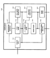
以下、本実施の形態におけるシステムの構成を図1を用いて説明する。BM−SC701〜SGSN703までのノードは従来技術における図7に記述したものと同じである。
The system configuration in the present embodiment will be described below with reference to FIG. The nodes from BM-
無線網中継装置101は従来技術の場合と同様に、MBMSのパケットの中継を行う。また、本実施の形態においては従来技術と同じ動作に加え、無線網制御装置102同士の間におけるMBMSのパケットの伝送状態の把握を行う。第一無線網制御装置102a、第二無線網制御装置102bは配下の無線アクセス網の制御を行う。以下の説明では、第一無線網制御装置102a、第二無線網制御装置102bを総称して無線網制御装置102という。
The wireless
第一基地局103aと第二基地局103bはともに有線の信号と無線データの変換を行い、伝送する。以下、第一基地局103a、第二基地局103bを総称して基地局103という。本実施の形態においては無線網制御装置102と基地局103は1対1の関係を持っているとする。なお、本発明はコアネットワークのノードまたは無線網中継装置と無線網制御装置間の処理手順に関するため、無線網制御装置と基地局の関係が1対1でない場合も同様の効果が得られる。
Both the
端末104は、無線通信を行う。説明の便宜上、端末104がセルA内にあるとき端末104a、セルAおよびセルBの両方にまたがるエリアにあるとき端末104b、セルB内にあるとき端末104cという。また、端末104aは、端末104b→端末104cと移動する。端末104a、端末104bは第一基地局103aと通信を行い、端末104bと端末104cは第二基地局103bと通信を行う。
The terminal 104 performs wireless communication. For convenience of explanation, the terminal 104a is referred to as the terminal 104a when the terminal 104 is in the cell A, the terminal 104b when the terminal 104 is within the cell A and the cell B, and the terminal 104c when the terminal 104 is within the cell B. The
セルA、セルBはそれぞれ第一基地局103aと第二基地局103bの通信可能範囲である。
Cell A and cell B are communicable ranges of the
図2は無線網中継装置101の内部構成を示す。CN通信部(GW)201はコアネットワーク(CN)のSGSN703などのノードと通信を行う手段である。3GPPにおけるRNC側のIuインタフェースを含む。CN−UTRAN相互接続部202は、Iuの信号を中継する無線網中継装置101と接続された(複数の)無線網制御装置102の各識別子を変換して、SGSN703等のコアネットワークのノードに対して、無線網中継装置101が1台の無線網制御装置として制御できるようにする。
FIG. 2 shows the internal configuration of the wireless
無線網制御装置通信部(GW)203は、無線網制御装置102に対して通信を行う手段である。3GPPにおけるコアネットワーク側のIuインタフェースを含む。
The wireless network control device communication unit (GW) 203 is means for communicating with the wireless
MBMS通信路制御部(GW)204は、無線網中継装置101に接続された無線網制御装置との間のMBMSのパケットの通信路を管理する手段である。MBMS伝送制御部(GW)205は、MBMS通信路制御部(GW)204の管理情報に従い、CN無線部(GW)201で受信したパケットをコピーし、無線網中継装置101からコピーしたパケットを出力させる。無線網中継装置全体制御部206は上記以外の制御を行う。
The MBMS communication path control unit (GW) 204 is a means for managing the communication path of MBMS packets with the radio network controller connected to the radio
図3は無線網制御装置102の内部構成を示す。CN通信部(RNC)301はSGSN703等のコアネットワークのノードや無線網中継装置101と通信を行う手段である。本実施の形態においては、無線網中継装置101のみと通信を行うものとする。
FIG. 3 shows the internal configuration of the
UTRAN制御部302は無線アクセス網(UTRAN : Universal Terrestrial Radio Access Network)の制御を行う手段である。3GPP TS25.331で規定されるRRC(Radio Resource Control、端末と無線網制御装置間のプロトコル)の動作を含む。
The
パケット無線信号変換部303は、CN通信部(RNC)301またはUTRAN制御部302におけるパケット信号を無線データに変換する手段である。3GPPにおけるPDCP(3GPP TS25.323、Packet Data Convergence Protocol)とRLC(3GPP TS25.322、Radio Link Control)の機能を含む。無線信号伝送部304は無線データを基地局103が用いるチャネルデータに変更し、伝送する手段である。3GPPにおけるMAC(3GPP TS25.321、Meda Access Control)の機能を含む。
The packet radio
基地局通信部305は基地局103との通信を行う。3GPPにおけるIubインタフェースや網間のトランスポートプロトコル等の機能を含む。無線網制御装置通信部(RNC)306は、他の無線網制御装置102と通信を行う。3GPPのIurインタフェースの機能を含む。無線網制御装置全体制御部307は、監視制御など、他の機能要素で実行されない制御を行う。MBMS通信路制御部(RNC)308は、無線網制御装置102の配下で、無線網中継装置101から入力されるMBMSのパケットを送出する先の端末104を管理する。MBMS伝送制御部(RNC)309は、受信したパケットをMBMS通信路制御部(RNC)308で管理する伝送先に対して、コピーし伝送する手段である。
The base
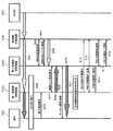
以下、本実施の形態の動作を示すシーケンス図である図4を用いて説明する。図4において、白抜きの矢印はパケットデータの流れを示し、斜線を付した矢印は無線データの流れを示す。図4において、信号401〜無線データ405までは従来技術の動作を示す図8における信号801〜無線データ805までと同じである。
Hereinafter, description will be given with reference to FIG. 4 which is a sequence diagram showing the operation of the present embodiment. In FIG. 4, white arrows indicate the flow of packet data, and hatched arrows indicate the flow of wireless data. In FIG. 4, signals 401 to
本実施の形態においては、従来技術における無線網中継装置708と第二無線網制御装置704b間のトラフィックを削減するため、Drift RNC向けのパケットデータをServing RNCである第一無線網制御装置102aから伝送させる。そのため、第二無線網制御装置102bは、第一無線網制御装置102aとの無線リンクを確立すると、無線データに併せてパケットデータを伝送させるための要求であるMBMS伝送要求406を第一無線網制御装置102aに対して出力する。
In the present embodiment, in order to reduce traffic between the radio
このとき、第二無線網制御装置102bの内部では以下の処理が行われる。UTRAN制御部302が第一無線網制御装置102aとの無線リンクを確立する(405)と、その情報と、第二無線網制御装置102bがDrift RNCであることがMBMS通信路制御部(RNC)308に伝達される。このとき、これら2つの情報に加えて第二無線網制御装置102bに対してMBMSのパケットが伝送されていないため、MBMS通信路制御部(RNC)308は無線データの伝送元の無線網制御装置102aからMBMSのデータをパケットでも受け取ることを決める。また、必要に応じて無線網制御装置通信部(RNC)306がパケットの受信準備を行う。受信準備は例えばIP網におけるポートの開設処理、ATMにおけるパスの開設処理である。以降、パケットデータまたは無線データが入力される装置または機能ブロックにおいては、特に記述がない場合でも、データの入力に先立ち、当該データの受信準備を必要に応じて行うものとする。なお、他の第二無線網制御装置102bが端末104bと同じMBMSのパケットを他の端末に対して無線網中継装置101から伝送している場合は、その端末に対して伝送されているパケットを変換して、端末104bに対して伝送する無線データとする。
At this time, the following processing is performed inside the second
よって、MBMS通信路制御部(RNC)308はUTRAN制御部302に対して無線網制御装置通信部(RNC)306経由で前記のMBMS伝送要求406を第一無線網制御装置102aに対して出力するように要求し、MBMS伝送要求406が第一無線網制御装置102aに対して出力される。
Therefore, the MBMS communication path control unit (RNC) 308 outputs the
MBMS伝送要求406に対して、第一無線網制御装置102aはパケットデータの出力を第二無線網制御装置102bに対して開始する。このとき、第一無線網制御装置102aの内部では以下の処理が行われる。無線網制御装置通信部(RNC)306によるMBMS伝送要求406が入力されると、MBMS通信路制御部(RNC)308が検出し、MBMS伝送制御部(RNC)309に対して該当のMBMSのパケットデータを第二無線網制御装置102bに対して出力するように要求する。
In response to the
第二無線網制御装置102bは端末104bに対して第二基地局103bを介して無線データを伝送する。このとき、第二無線網制御装置102bの内部では以下の処理が行われる。伝送されるMBMSのパケットデータは、第二無線網制御装置のCN通信部(RNC)301に入力される。そしてMBMS伝送制御部(RNC)309が、出力対象の基地局の数だけ入力されたパケットデータを複製する。その複製したパケットデータはパケット無線信号変換部303に出力される。パケット無線信号変換部303は、パケットデータを無線データに変換する。さらにこの無線データは無線信号伝送部304によりチャネルデータに変換され、基地局通信部305により、第二基地局103bに対して出力される。
The second
また、第一無線網制御装置102aは、MBMS伝送開始通知408を無線網中継装置101に対して出力する。これにより、第二無線網制御装置102bに対してパケットデータが伝送されていることを、無線網中継装置101が把握することができる。第一無線網制御装置102aの内部では、MBMS通信路制御部(RNC)308がMBMS伝送開始通知408を生成し、UTRAN制御部302経由でCN通信部(RNC)301から出力させる。
Also, the first
一方、無線網中継装置101にMBMS伝送開始通知408が入力されると、CN−UTRAN相互接続部202を経てMBMS通信路制御部(GW)204が検出し、パケットデータが伝送されていることを記録する。チャネル開設処理409と無線データ伝送処理410はそれぞれ従来技術におけるチャネル開設処理809と無線データ伝送処理810と同じである。
On the other hand, when the MBMS
なお、MBMS伝送開始通知408が存在すれば、第一無線網制御装置102aと第二無線網制御装置102bとの間でパケットデータを伝送しない場合でも同様の無線網中継装置101と無線網制御装置102b間のトラフィック削減の効果が得られることは容易に類推できる。
If the MBMS
なお、必要に応じて、停止対象のMBMSを指定したMBMS伝送停止通知を第二無線網制御装置102bから第一無線網制御装置102aに対して送出することにより、該当のMBMSのパケットデータの伝送を停止することが可能なことも容易に類推できる。
If necessary, the MBMS transmission stop notification specifying the MBMS to be stopped is transmitted from the second
なお、本実施の形態では無線網中継装置を配置することを仮定したが、SGSN703にMBMS伝送開始通知に対応してMBMSのパケット伝送の経路を管理する機能を追加することによって、無線網中継装置101がない場合でも本実施の形態を適用できる。
In this embodiment, it is assumed that a radio network relay device is arranged. However, by adding a function for managing the MBMS packet transmission path to the
なお、MBMSでないパケット伝送を行っているときに無線網制御装置102の切り替えを行う場合でも、本実施の形態と同様に切替処理中に移動元から移動先の無線網制御装置102に対してパケットを伝送することにより、同様の効果が得られることも類推可能である。
Even when the
以上、本実施の形態においては、端末104の移動時においても、無線網中継装置101と無線網制御装置102bの間にMBMSのパケットデータが伝送されることを防止することにより、トラフィックを削減する効果が得られる。
As described above, in the present embodiment, even when the terminal 104 moves, traffic is reduced by preventing MBMS packet data from being transmitted between the radio
(第2の実施の形態)
以下、第2の実施の形態を説明する。最初に、第2の実施の形態の概要について説明する。本実施の形態においては、端末104が新しいセルBに移動した後に、接続する無線網制御装置102の切り替えの際に切替元と切替先のチャネルの同期をとることで、パケットの損失を低減する方法を示す。
(Second Embodiment)
Hereinafter, a second embodiment will be described. First, the outline of the second embodiment will be described. In the present embodiment, after the terminal 104 moves to a new cell B, the packet loss is reduced by synchronizing the switching source channel and the switching destination channel when switching the radio
本実施の形態の切替方式の概要を図5(a)〜図5(c)に示した。本実施の形態においては、移動する前に端末104cが接続していた無線網制御装置102aから、移動先のセルBを制御する無線網制御装置102bに伝送路を2段階に分けて切り替える手順を示す。図5(a)は端末104cがセルAから出てセルBに進入した直後の状態、図5(b)は1段階目の切替え、図5(c)は2段階目の切替えを行った後の状態をそれぞれ示す。
The outline of the switching method of this embodiment is shown in FIGS. 5 (a) to 5 (c). In the present embodiment, a procedure for switching the transmission path in two stages from the
図5においては、構成要素は第1の実施の形態と同じである。また、線は各チャネルの伝送路を示す。点線はパケットデータの伝送路、実線は無線データの伝送路を示す。ここではRLCとMAC層の間のDTCH、MTCH等の論理チャネルを想定している。なお、本実施の形態の方式は、SGSN703または無線網中継装置101間のデータ伝送路に関するため、MBMSで用いられるDTCHまたはMTCHのいずれにも適用可能である。パケットデータの伝送路を伝送するパケットは、例えばIPパケットまたは3GPPのGTP(GPRS Tunneling Protocolによってカプセル化されたパケットを想定する。各々のパケットは、SGSN703または無線網制御装置102bによって付与されるシーケンス番号を含み、シーケンス番号はパケットを出力するノードが、パケットを1個出力する毎に1ずつ増加させていく。
In FIG. 5, the constituent elements are the same as those in the first embodiment. A line indicates a transmission path of each channel. A dotted line indicates a transmission path for packet data, and a solid line indicates a transmission path for wireless data. Here, logical channels such as DTCH and MTCH between the RLC and the MAC layer are assumed. In addition, since the system of the present embodiment relates to the data transmission path between the
図5(a)では、端末104cが移動した直後に、無線網中継装置101から第二無線網制御装置102bに対して以下2つの経路で伝送を行っていることを示す。すなわち、(1)移動元の第一無線網制御装置102aを経由し、移動元の第一無線網制御装置102aから移動先の第二無線網制御装置102bへ無線データを伝送、(2)移動元の第一無線網制御装置102aを経由し、移動元の第一無線網制御装置102aから移動先の無線網制御装置102bへパケットデータを伝送、の経路である。
FIG. 5A shows that immediately after the terminal 104c moves, transmission is performed from the wireless
移動先の第二無線網制御装置102bに対する伝送路切り替えは、端末104cに対して伝送を行っている経路(1)から、次に示す経路(3)に切り替えを行うことによって行われる。すなわち、(3)移動元の第一無線網制御装置102aを経由せず、無線網中継装置101と移動先の無線網制御装置102bとの間でパケットデータを伝送する経路に切り替える。
Transmission path switching for the second
ただし、図5(a)の状態では、第二無線網制御装置102bは、経路(1)の無線データを中継するだけでパケットのシーケンス番号の知識を持たないので、経路(3)との同期をとることができない。
However, in the state of FIG. 5A, the second
そこで、最初に第一無線網制御装置102aにおいて経路(1)から経路(2)への切り替えを行う。また、経路(3)の伝送も開始する。その結果が図5(b)である。第一無線網制御装置102aは、これらの伝送路のデータの両方を管理しており、パケット伝送路502のパケットと無線データ伝送路503のデータフレームの対応を把握しているため、損失を発生させずに伝送路の切り替えを行うことができる。なお、この切り替えによって無線データ伝送路503の伝送は停止される(図5(b)参照)。
Therefore, first, the first
次に、第二無線網制御装置102bにおいて経路(2)から経路(3)への切り替えを行う。その結果が図5(c)である。この切り替えにおいては、第二無線網制御装置102bはパケット伝送路502とパケット伝送路504の両方のパケットのシーケンス番号を取得できるため、損失を発生させずに伝送路を切り替えることができる。なお、この切り替えの後、パケット伝送路502の伝送は停止される(図5(c)参照)。
Next, switching from the path (2) to the path (3) is performed in the second
以下、図6を用いて詳細に切り替え手順の説明を行う。信号601は本実施の形態の初期状態における伝送路の状態を示す。第1の実施の形態の制御によって、この状態となる。この時点Iで、図5(a)のように、無線網中継装置101から第二無線網制御装置102bに対して二本の伝送路を用いてデータが伝送されている。第一無線網制御装置102aがServing RNC、第二無線網制御装置102bがDrift RNCとして動作している。
Hereinafter, the switching procedure will be described in detail with reference to FIG. A
次に、イベント602において、第一無線網制御装置102aが、端末104cのServing RNCの切り替えを行うことを決める。Serving RNCの切り替えの理由としては、無線網制御装置間の負荷を分散させる、移動後の端末104cと第二基地局103b間の通信品質が閾値を超え安定するなどが考えられるが、この理由に関係なく本実施の形態は適用可能である。
Next, at
第一無線網制御装置102aは、Serving RNCの切り替えを決定すると、移動先の無線網制御装置に対して、切り替えた以降のチャネルを指定したMBMSチャネル切替要求603を出力する。MBMSチャネル切替要求603に対して、第二無線網制御装置102bはMBMS登録604の手順を使って、無線網中継装置101に対して、端末104cが加入しているMBMSに登録するように要求する。本手順は3GPP TS25.346におけるRNC Registration ProcedureのMBMS REGISTRATION REQUESTとMBMS REGISTRATION RESPONSEで実現できる。なお、第二無線網制御装置102bが既に当該のMBMSに登録済みの場合は、この手順は不要である。
When the first
登録が終了すると、第二無線網制御装置102bは端末104cが加入するMBMSを指定したMBMSセッション開始605の手順を用いて、無線網中継装置101に対して、第二無線網制御装置102bに対するMBMSのパケットデータの伝送を開始するように要求する。本手順は3GPP TS25.346におけるMBMS Session Start手順のMBMS SESSION START REQUESTとMBMS SESSION START RESPONSEを用いて実現できる。
When the registration is completed, the second
MBMSセッション開始手順605の結果、無線網中継装置101は第二無線網制御装置102bに対するMBMSパケットの伝送(信号606)を開始する。このとき、無線網中継装置101の内部では以下の処理が行われる。MBMSセッション開始605の手順が無線網制御装置通信部(GW)203に入力され、CN−UTRAN相互接続部202によって、MBMS通信路制御部(CN)204に転送される。MBMS通信路制御部(GW)204は、無線網中継装置101が第二無線網制御装置102bに対して、端末104cに対するMBMSのパケットを伝送していないことを把握している。よって、MBMSセッション開始605の手順を認識すると、MBMS伝送制御部(CN)205を制御して当該MBMSのパケット伝送を開始させる。これが信号606である。
As a result of the MBMS
また、第二無線網制御装置102bは第一無線網制御装置102aに対してMBMSチャネル切り替え応答607を出力する。なお、可能なら第二無線網制御装置102bが第一無線網制御装置102aに対して、伝送路の切替が可能になるタイミングを通知しても良い。通知した場合、後述のMBMS信号切替要求608において、第一無線網制御装置102aが伝送路を切り替るタイミングを決定するときに第二無線網制御装置102bから通知されたタイミングを用いることで、より確実に伝送路を切り替えるタイミングを設定することが可能になる。
The second
第一無線網制御装置102aはMBMSチャネル切替応答607が入力されると、第二無線網制御装置102bに対して、端末104cに対して伝送するデータを無線データ伝送路503aからパケットデータ伝送路502aに切り替えるMBMS信号切替要求608を出力する。MBMS信号切替要求608において、第一無線網制御装置102aは切り替えるタイミングを指定する。タイミングを指定する方法は、時刻、無線データのフレーム番号、パケットデータのシーケンス番号のいずれでもよい。
When the MBMS
このとき、第一無線網制御装置102aの内部では以下の処理が行われる。MBMS信号切替要求608を出力する際に、MBMS通信路制御部(RNC)308は無線データの出力を停止するタイミングを算出する。なお、MBMSチャネル切替応答607において、伝送路の切替が可能になるタイミングが指定されているときには、その時刻より後に無線データの出力を停止するタイミングを指定する。
At this time, the following processing is performed inside the first
タイミングを算出すると、MBMS通信路制御部(RNC)308はMBMS伝送制御部(RNC)309に対して、無線データの出力を指定されたタイミングが来たときに停止するよう指示する。また、MBMS通信路制御部(RNC)308はMBMS信号切替要求608を、指定するタイミング、切替先のパケットデータ伝送路を識別する情報を格納することによって生成し、無線網制御装置通信部(RNC)306を用いて第二無線網制御装置102bに対して出力する。
When the timing is calculated, the MBMS communication path control unit (RNC) 308 instructs the MBMS transmission control unit (RNC) 309 to stop the output of wireless data when the designated timing comes. Also, the MBMS communication path control unit (RNC) 308 generates an MBMS signal switching request 608 by storing information for identifying the designated timing and switching destination packet data transmission path, and the radio network controller communication unit (RNC) ) 306 to the second
MBMS信号切替要求608に対して、第二無線網制御装置102bは、伝送路切替の可否を判定し、第一無線網制御装置102aに対してMBMS信号切替応答609を出力する。本実施の形態においては伝送路切替が可能である旨を応答する。イベント610において、第二無線網制御装置102bはMBMS信号切替要求608に指定されたタイミングで、端末104cに対して伝送するデータを無線データ伝送路503aからパケットデータ伝送路502aに切り替える。
In response to the MBMS signal switching request 608, the second
このとき、第二無線網制御装置102bの内部では以下の処理が行われる。MBMS信号切替要求608は、CN通信部(RNC)301とUTRAN制御部302を経由して、MBMS通信路制御部(RNC)308に転送される。MBMS通信路制御部(RNC)308は、MBMS信号切替要求608で指定されたタイミングになったときに、伝送路を無線データ伝送路503aからパケットデータ伝送路502aに切り替える指示を、MBMS伝送制御部(RNC)309に行う。
At this time, the following processing is performed inside the second
MBMS伝送制御部(RNC)309は、もともと無線網制御装置通信部(RNC)306経由で第一無線網制御装置102aから入力された無線データを無線信号伝送部304と基地局通信部305経由で基地局103bに対して出力している。また、この時点においては、第一無線網制御装置102aからのパケットデータも無線網制御装置通信部(RNC)306経由で入力されている。
The MBMS transmission control unit (RNC) 309 transmits the radio data originally input from the first radio
そこで、MBMS伝送制御部(RNC)309は、無線データのフレーム番号又はパケットデータのシーケンス番号の少なくとも一方を確認し、MBMS通信路制御部(RNC)308によって指定されたタイミングになったことを検出すると、無線データの無線信号伝送部304経由の出力を停止し、無線網制御装置通信部(RNC)306経由で入力されるパケットデータをパケット無線信号変換部303で新規の無線データへの変換を開始し、無線信号伝送部304と基地局通信部305経由で第二基地局103bに対して出力する。
Therefore, the MBMS transmission control unit (RNC) 309 confirms at least one of the frame number of wireless data or the sequence number of packet data and detects that the timing specified by the MBMS communication path control unit (RNC) 308 has come. Then, the output of the wireless data via the wireless
第一無線網制御装置102aは、MBMS信号切替要求608で指定したタイミングが過ぎると、第二無線網制御装置102bにおける無線データ伝送路503aからパケットデータ伝送路502aへの伝送路変更が完了したと判断して、第二無線網制御装置102bに対する無線データ伝送611を停止する。本処理の完了の時点IIで、図5(b)の状態になる。
When the timing specified by the MBMS signal switching request 608 has passed, the first
このとき、第一無線網制御装置102aの内部では以下の処理が行われる。第一無線網制御装置102aから第二無線網制御装置102bに対する無線データは、第一無線網制御装置102aにおけるMBMS伝送制御部309によって、無線網制御装置通信部(RNC)306を用いて第二無線網制御装置102bに対して出力されている。そこで、MBMS伝送制御部(RNC)309は、無線データのフレーム番号又はパケットデータのシーケンス番号の少なくとも一方を確認し、MBMS通信路制御部(RNC)308によって指定されたタイミングになったことを検出すると、無線データの無線信号伝送部304経由の出力を停止させる。
At this time, the following processing is performed inside the first
図5(b)の状態からは、Serving RNCの切替を行う。これは3GPP TR25.931のSRNS Relocationと同様のシグナリングを用いて行うことができる。 まず、第一無線網制御装置102aは切替予備通知612を無線網中継装置101に対して出力する。本メッセージは3GPP TS25.413のRELOCATION REQUIREDメッセージで実現可能である。
From the state of FIG. 5B, the Serving RNC is switched. This can be performed using the same signaling as SRNS Relocation of 3GPP TR25.931. First, the first
無線網中継装置101は切替予備通知612が入力されると、無線網中継装置101に対してRNC切替要求・応答613の手順を実施する。切替先の伝送路(RAB、Radio Access Bearer)が指定される。RNC切替要求・応答613は3GPP TS25.413のRELOCATION REQUESTとRELOCATION REQUEST ACKNOWLEDGE手順で実現できる。ただし、通常の無線網制御装置の切替手順においては、無線網制御装置間には無線データが伝送されているが、本実施の形態においては、パケットデータが伝送されているため、パケットデータの切替を行うことを指定する必要がある。
When the switch preliminary notification 612 is input, the radio
第一無線網制御装置102aは、RNC切替要求・応答613が完了すると、端末104cに関するRNC切替実行要求614を第二無線網制御装置102bに対して出力する。RNC切替実行要求614では、上り・下りの伝送路を切り替えるパケットのシーケンス番号を指定する。この番号をNとする。
When the RNC switching request /
イベント615において、第二無線網制御装置102bは伝送路の切替えを実施する。第二無線網制御装置102bは、パケットのシーケンス番号がN−1以下のパケットについては、パケットデータ伝送路502を経由して第一無線網制御装置102aから受信したパケットを無線データに変換して端末104cに対して出力する。パケットのシーケンス番号がN以降のパケットについては、受信側の伝送路を切り替えて、パケットデータ伝送路504を経由して無線網中継装置101から受信したパケットを無線データに変換して出力する。このように移動元の第一無線網制御装置102a、および無線網中継装置101の両者からパケットを受信し、パケットのシーケンス番号に基づいて切替えを実施することで、データ無損失の切替を実行することが可能になる。
At
同時に無線網中継装置101も、上りのパケットに関してRNC切替・応答613の手順で指定された上り側のシーケンス番号において、第一無線網制御装置102aから第二無線網制御装置102bのパケットを上り伝送に使うように伝送路を変更する。
At the same time, the radio
このとき、第二無線網制御装置102bの内部では以下の処理が行われる。第一無線網制御装置102aからのパケットデータは、無線網制御装置通信部(RNC)306に入力され、MBMS伝送制御部(RNC)309がパケット無線信号変換部303に出力している。一方、無線網中継装置101のからのMBMSのパケットデータは、CN通信部(RNC)301に入力され、同様にMBMS伝送制御部(RNC)309とパケット無線信号変換部303を経由している。
At this time, the following processing is performed inside the second
そこでRNC切替実行要求614がその切替を行うタイミングの情報と共に無線網制御装置通信部(RNC)306を介してMBMS通信路制御部(RNC)308に入力される。MBMS通信路制御部(RNC)308はMBMS伝送制御部(RNC)309に対して、MBMSのパケットのシーケンス番号がNになったときに、CN通信部(RNC)301経由のMBMSのパケットに切り替えるように指示する。この指示により、MBMS伝送制御部(RNC)309は、当該MBMSのパケットのシーケンス番号がNになったときに、CN通信部(RNC)301経由で無線網中継装置101から入力されるMBMSのデータパケットからの信号に切り替える。このように無線網制御装置102が、入力されるMBMSのシーケンス番号又はフレーム番号の切替えを行うことで、パケットの損失を低減することが可能である。
Therefore, the RNC switching execution request 614 is input to the MBMS communication path control unit (RNC) 308 through the radio network controller communication unit (RNC) 306 together with information on the timing for performing the switching. The MBMS communication path control unit (RNC) 308 switches to the MBMS transmission control unit (RNC) 309 to switch to the MBMS packet via the CN communication unit (RNC) 301 when the MBMS packet sequence number becomes N. To instruct. In response to this instruction, the MBMS transmission control unit (RNC) 309 causes the MBMS data input from the radio
RNC切替実行要求が入力されると、第二無線網制御装置102bはRNC切替検出通知616を無線網中継装置101に出力する。また、伝送路の切替が終了すると、第二無線網制御装置102bはRNC切替完了通知617を無線網中継装置101に出力する。以上でServing RNCの切替処理は終了する。
When the RNC switch execution request is input, the second
また、Serving RNCの切替処理が終了したら、無線網中継装置101は第一無線網制御装置102aに対して、端末104cに関する第一無線網制御装置102aと第二無線網制御装置間のチャネルを停止させるRNC間伝送停止618の手順を第一無線網制御装置102aに対して出力する。これに対して、信号619で第一無線網制御装置102aは該当するパケットデータ伝送路504aの伝送を停止させる。この時点IIIで、図5(c)の状態になる。
When the switching process of the Serving RNC is completed, the radio
このとき、第一無線網制御装置102aの内部では以下の処理が行われる。RNC間伝送停止要求618が無線網制御装置通信部(RNC)306に入力されると、MBMS通信路制御部(RNC)308が要求を検出し、要求に従いMBMS伝送制御部(RNC)309に対して、当該端末104cに対するMBMSパケットの伝送を停止させるよう指示する。MBMS伝送制御部(RNC)309は、指示に従い、パケット無線信号変換部303の制御を行い、無線信号伝送部304に対するパケット伝送を停止させる。
At this time, the following processing is performed inside the first
以上、本実施の形態においては、移動元の無線網制御装置102aと移動先の無線網制御装置102bとの間の切替えを2段階に分割し、それぞれにおいて同期を取りながら切替えを行うことによって、損失のない無線網制御装置102の切替方法を実現できる。
As described above, in the present embodiment, the switching between the movement-source wireless
なお、最初の状態においては、第一無線網制御装置102aと端末104c間でデータ伝送されていないが、データが伝送されている場合でも、本実施の形態の適用は可能である。
In the initial state, data is not transmitted between the first
なお、本実施の形態は、第1の実施の形態の実現が前提となっているが、最初に第二無線網制御装置102bから第一無線網制御装置102aに対してパケットが伝送されていない場合でおいても、無線網制御装置102の切替えを予測するか、または無線網制御装置102からのMBMSチャネル切替要求が入力された後に、新たに第一無線網制御装置102aから第二無線網制御装置102bへのパケット伝送を開始させることにより、途中からのシーケンスを応用することで本実施の形態と同様の効果が得られる。
This embodiment is premised on the realization of the first embodiment, but no packet is initially transmitted from the second
なお、図6においてRNC間伝送停止618の手順は、実際に第一無線網制御装置102aと第二無線網制御装置102b間の伝送が停止される前に完了しているように描かれているが、実際には、伝送停止を示す応答が第一無線網制御装置102aにから信号619の後に出力される場合でも本実施の形態と同様の効果が得られる。同様に、他の手順に関しても、本実施の形態の意図を逸脱しない場合は、手順の順番を変えても本実施の形態と同様の効果が得られる。
In FIG. 6, the procedure of the
なお、SGSN703がMBMSチャネル切替要求に対する処理に対応させることにより、無線網中継装置102を配置しなくても、本実施の形態と同様の効果が得られる。
Note that the
なお、MBMS以外のパケット通信サービスに対しても、無線網制御装置の切替の際に移動元と移動先の無線網制御装置102a,102bに対して、端末が利用中のサービスのパケットを伝送し、本実施の形態と同様のシーケンスで処理を行うと、本実施の形態と同様に損失のない切替えが可能になる。
For packet communication services other than MBMS, the packet of the service being used by the terminal is transmitted to the source and destination
以上説明したように、本発明は、一の無線網制御装置から無線データを受信中の携帯端末が他の無線網制御装置と通信可能なエリアに入ったときに、一の無線網制御装置から他の無線網制御装置へデータパケットを送信するので、コアネットワークと無線網制御装置との間のトラフィックを低減できるというすぐれた効果を有し、移動体通信システムの無線アクセス網において、例えば、マルチキャストを用いたサービスの提供中に端末がセルを移動した際に通信を継続される無線網制御装置の制御方法として有用である。 As described above, according to the present invention, when a mobile terminal that is receiving wireless data from one wireless network control device enters an area where it can communicate with another wireless network control device, Since the data packet is transmitted to another radio network controller, it has an excellent effect that the traffic between the core network and the radio network controller can be reduced. In the radio access network of the mobile communication system, for example, multicast This is useful as a control method of a radio network controller that can continue communication when a terminal moves between cells while providing a service using.
101 無線網中継装置
102a 第一無線網制御装置
102b 第二無線網制御装置
103a 第一基地局
103b 第二基地局
104a 端末
104b 端末
104c 端末
201 CN通信部(GW)
202 CN−UTRAN相互接続部
203 無線網制御装置通信部(GW)
204 MBMS通信路制御部(GW)
205 MBMS伝送制御部(GW)
206 無線網中継装置全体制御部
301 CN通信部(RNC)
302 UTRAN制御部
303 パケット無線信号変換部
304 無線信号伝送部
305 基地局通信部
306 無線網制御装置通信部(RNC)
307 無線網制御装置全体制御部
308 MBMS通信路制御部(RNC)
309 MBMS伝送制御部(RNC)
701 BM−SC
702 GGSN
703 SGSN
708 無線網中継装置
704a 第一無線網制御装置
704b 第二無線網制御装置
705a 第一基地局
705b 第二基地局
706 端末
101 wireless
202 CN-
204 MBMS channel control unit (GW)
205 MBMS transmission control unit (GW)
206 Wireless network relay device
302
307 Radio network controller
309 MBMS Transmission Control Unit (RNC)
701 BM-SC
702 GGSN
703 SGSN
708
Claims (8)
一の無線網制御装置から無線データを受信中の携帯端末が、前記一の無線網制御装置と異なる他の無線網制御装置と通信可能なエリアに入った場合に、
前記一の無線網制御装置にて変換した無線データを前記一の無線網制御装置から前記他の無線網制御装置に送信し、
前記他の無線網制御装置が前記一の無線網制御装置から受信した無線データを前記携帯端末に送信し、
前記一の無線網制御装置がコアネットワークから受信したデータパケットを前記他の無線網制御装置に送信する、
ことを特徴とする無線網制御方法。 Control of a radio access network comprising: a radio network controller that converts data packets received from a core network into radio data and transmits the radio data to a mobile terminal; and a mobile terminal that receives radio data from the radio network controller A method,
When a mobile terminal that is receiving wireless data from one wireless network control device enters an area where it can communicate with another wireless network control device different from the one wireless network control device,
Transmitting the radio data converted by the one radio network control device from the one radio network control device to the other radio network control device;
The other wireless network control device transmits the wireless data received from the one wireless network control device to the portable terminal;
The one radio network controller transmits a data packet received from the core network to the other radio network controller,
A wireless network control method.
前記他の無線網制御装置が前記携帯端末に送信する無線データを、前記一の無線網制御装置から受信した無線データから前記変換によって得られた無線データに切り替え、
前記他の無線網制御装置がコアネットワークからデータパケットを受信し、
前記他の無線網制御装置が前記変換に用いるデータパケットを、前記一の無線網制御装置から受信したデータパケットから前記コアネットワークから受信したデータパケットに、両データパケットの同期をとりながら切り替える、
ことを特徴とする請求項1に記載の無線網制御方法。 The other radio network controller converts the data packet received from the one radio network controller into radio data,
The wireless data transmitted to the mobile terminal by the other wireless network control device is switched from the wireless data received from the one wireless network control device to the wireless data obtained by the conversion,
The other radio network controller receives a data packet from the core network;
The data packet used for the conversion by the other radio network controller is switched from the data packet received from the radio network controller to the data packet received from the core network while synchronizing both data packets.
The wireless network control method according to claim 1, wherein:
ことを特徴とする請求項3に記載の無線網制御方法。 Data from the one radio network controller to the other radio network controller after the other radio network controller starts transmitting radio data to the portable terminal using a data packet from the core network Stop sending packets,
The radio network control method according to claim 3.
一の無線網制御装置から無線データを受信中の携帯端末が、前記一の無線網制御装置と異なる他の無線網制御装置と通信可能なエリアに入った場合に、
前記一の無線網制御装置にて変換した無線データを前記一の無線網制御装置から前記他の無線網制御装置に送信し、
前記他の無線網制御装置が前記一の無線網制御装置から受信した無線データを前記携帯端末に送信し、
前記一の無線網制御装置がコアネットワークから受信したデータパケットを前記他の無線網制御装置に送信する、
ことを特徴とする無線網制御システム。 A radio network control system comprising: a radio network controller that converts a data packet received from a core network into radio data and transmits the radio data to a mobile terminal; and a mobile terminal that receives radio data from the radio network controller. There,
When a mobile terminal that is receiving wireless data from one wireless network control device enters an area where it can communicate with another wireless network control device different from the one wireless network control device,
Transmitting the radio data converted by the one radio network control device from the one radio network control device to the other radio network control device;
The other wireless network control device transmits the wireless data received from the one wireless network control device to the portable terminal;
The one radio network controller transmits the data packet received from the core network to the other radio network controller;
A wireless network control system.
前記他の無線網制御装置が前記携帯端末に送信する無線データを、前記一の無線網制御装置から受信した無線データから前記変換によって得られた無線データに切り替え、
前記他の無線網制御装置がコアネットワークからデータパケットを受信し、
前記他の無線網制御装置が前記変換に用いるデータパケットを、前記一の無線網制御装置から受信したデータパケットから前記コアネットワークから受信したデータパケットに、両データパケットの同期をとりながら切り替える、
ことを特徴とする請求項5に記載の無線網制御システム。 The other radio network controller converts the data packet received from the one radio network controller into radio data,
The wireless data transmitted to the mobile terminal by the other wireless network control device is switched from the wireless data received from the one wireless network control device to the wireless data obtained by the conversion,
The other radio network controller receives a data packet from the core network;
The data packet used for the conversion by the other radio network controller is switched from the data packet received from the radio network controller to the data packet received from the core network while synchronizing both data packets.
The wireless network control system according to claim 5, wherein:
データパケットを無線データに変換する手段と、
データパケットを変換して得られた無線データを携帯端末に送信する手段と、
無線データ送信先の携帯端末が他の無線網制御装置と通信可能なエリアに入ったか否かを判定する手段と、
前記無線データ送信先の携帯端末が他の無線網制御装置と通信可能なエリアに入ったとの判定に応じて、前記無線データを前記他の無線網制御装置に送信する手段と、
前記コアネットワークから受信したデータパケットを前記他の無線網制御装置に送信する手段と、
を備えたことを特徴とする無線網制御装置。 Means for receiving data packets from the core network;
Means for converting data packets into wireless data;
Means for transmitting wireless data obtained by converting the data packet to the mobile terminal;
Means for determining whether or not the portable terminal of the wireless data transmission destination has entered an area where it can communicate with other wireless network control devices;
Means for transmitting the wireless data to the other wireless network control device in response to determining that the portable terminal of the wireless data transmission destination has entered an area in which communication with the other wireless network control device is possible;
Means for transmitting a data packet received from the core network to the other radio network controller;
A wireless network control device comprising:
他の無線網制御装置から受信した無線データを前記携帯端末に送信する手段と、
前記携帯端末に送信する無線データを、他の無線網制御装置から受信した無線データから、他の無線網制御装置から受信したデータパケットを変換して得られる無線データに切り替える手段と、
前記他の無線網制御装置が前記変換する手段にて変換するデータパケットを、前記他の無線網制御装置から受信したデータパケットから前記コアネットワークから受信したデータパケットに、両データパケットの同期をとりながら切り替える手段と、
を備えたことを特徴とする請求項7に記載の無線網制御装置。 Means for receiving radio data and data packets from other radio network controllers;
Means for transmitting wireless data received from another wireless network control device to the portable terminal;
Means for switching wireless data to be transmitted to the portable terminal from wireless data received from another wireless network control device to wireless data obtained by converting a data packet received from the other wireless network control device;
The data packet to be converted by the means for converting by the other radio network controller is synchronized with the data packet received from the core network from the data packet received from the other radio network controller. Means to switch while
The radio network controller according to claim 7, further comprising:
Priority Applications (3)
| Application Number | Priority Date | Filing Date | Title |
|---|---|---|---|
| JP2004166120A JP4452128B2 (en) | 2004-06-03 | 2004-06-03 | Radio network control method, radio network control system, and radio network control apparatus |
| US11/628,046 US7751820B2 (en) | 2004-06-03 | 2005-03-17 | Handoff method comprising network control apparatus that receives data packets from both the core network and the other network control apparatus wherein said received data packets will be transformed into wireless data |
| PCT/JP2005/004797 WO2005120119A1 (en) | 2004-06-03 | 2005-03-17 | Wireless network control method, wireless network control system, and wireless network control apparatus |
Applications Claiming Priority (1)
| Application Number | Priority Date | Filing Date | Title |
|---|---|---|---|
| JP2004166120A JP4452128B2 (en) | 2004-06-03 | 2004-06-03 | Radio network control method, radio network control system, and radio network control apparatus |
Publications (2)
| Publication Number | Publication Date |
|---|---|
| JP2005348154A JP2005348154A (en) | 2005-12-15 |
| JP4452128B2 true JP4452128B2 (en) | 2010-04-21 |
Family
ID=35463221
Family Applications (1)
| Application Number | Title | Priority Date | Filing Date |
|---|---|---|---|
| JP2004166120A Expired - Fee Related JP4452128B2 (en) | 2004-06-03 | 2004-06-03 | Radio network control method, radio network control system, and radio network control apparatus |
Country Status (3)
| Country | Link |
|---|---|
| US (1) | US7751820B2 (en) |
| JP (1) | JP4452128B2 (en) |
| WO (1) | WO2005120119A1 (en) |
Families Citing this family (19)
| Publication number | Priority date | Publication date | Assignee | Title |
|---|---|---|---|---|
| US8553643B2 (en) * | 2005-07-19 | 2013-10-08 | Qualcomm Incorporated | Inter-system handover using legacy interface |
| JP4859419B2 (en) * | 2005-09-14 | 2012-01-25 | 株式会社エヌ・ティ・ティ・ドコモ | Radio base station and user common data transmission method |
| EP1912377B1 (en) | 2006-10-15 | 2013-04-17 | Samsung Electronics Co., Ltd. | System and method for transmitting/receiving multicast/broadcast signal in a communication system |
| WO2008065712A1 (en) * | 2006-11-28 | 2008-06-05 | Panasonic Corporation | Wireless control apparatus, mobile station apparatus and wireless control method |
| EP1978762A1 (en) * | 2007-04-05 | 2008-10-08 | Matsushita Electric Industrial Co., Ltd. | Service content synchronization of multicast data for mobile nodes moving between networks with different radio access technologies |
| KR101398908B1 (en) * | 2007-05-22 | 2014-05-26 | 삼성전자주식회사 | Method and system for managing mobility in mobile telecommunication system using mobile ip |
| WO2009079653A2 (en) * | 2007-12-18 | 2009-06-25 | Zte U.S.A., Inc. | Wimax multicast broadcast services (mbs) efficient handover and power saving support for intra and inter-mbs zones |
| EP2265044B1 (en) * | 2008-03-31 | 2017-02-22 | Fujitsu Limited | Communication controller, communication control method, and communication control program |
| JP4809407B2 (en) * | 2008-09-12 | 2011-11-09 | 株式会社エヌ・ティ・ティ・ドコモ | Mobile communication system, radio network apparatus and method |
| KR101277099B1 (en) | 2008-10-31 | 2013-06-20 | 닛본 덴끼 가부시끼가이샤 | Mobile communication system, core network node, control station, base station, and communication method |
| JP5245752B2 (en) * | 2008-11-20 | 2013-07-24 | 富士通株式会社 | Access network gateway device |
| JP5107289B2 (en) * | 2009-03-19 | 2012-12-26 | 株式会社エヌ・ティ・ティ・ドコモ | Mobile communication method, radio base station, radio network controller, core network device, and gateway device |
| JP5365694B2 (en) * | 2009-08-26 | 2013-12-11 | 富士通株式会社 | Base station control device and communication system |
| CN102625395B (en) * | 2012-01-06 | 2015-12-02 | 华为终端有限公司 | Increase powerful processing method, radio network controller and terminal |
| WO2013151469A1 (en) * | 2012-04-03 | 2013-10-10 | Telefonaktiebolaget L M Ericsson (Publ) | Interference control between different radio communication systems involving user equipments |
| EP2912174B1 (en) * | 2012-10-25 | 2019-06-19 | Neumodx Molecular, Inc. | Method and materials for isolation of nucleic acid materials |
| EP2785135A1 (en) * | 2013-03-29 | 2014-10-01 | Alcatel Lucent | Enhancements to resource allocation for MBSFN transmission in an MBSFN area |
| CN105637905B (en) * | 2013-10-14 | 2019-09-13 | 华为技术有限公司 | For realizing the methods, devices and systems of PDN connection |
| CN105009638B (en) | 2014-01-03 | 2019-10-01 | 华为技术有限公司 | A kind of method for user device switching and base station |
Family Cites Families (7)
| Publication number | Priority date | Publication date | Assignee | Title |
|---|---|---|---|---|
| FI108772B (en) | 1998-03-31 | 2002-03-15 | Nokia Corp | Method for managing mobile connection |
| US6687249B1 (en) | 1998-08-25 | 2004-02-03 | Telefonaktiebolaget Lm Ericsson | Reconfiguring diversity legs during CN-RNC interface streamlining |
| JP2974019B1 (en) | 1998-08-26 | 1999-11-08 | 日本電気株式会社 | Mobile communication system, soft handover processing method, and storage medium in which the method is written |
| US20040125795A1 (en) * | 2000-02-18 | 2004-07-01 | Corson Mathew S | Telecommunications routing |
| KR100595583B1 (en) | 2001-07-09 | 2006-07-03 | 엘지전자 주식회사 | Method for transmitting packet data according to handover in a mobile communication system |
| KR20040016540A (en) * | 2002-08-17 | 2004-02-25 | 삼성전자주식회사 | Apparatus for transmitting/receiving data on handover in mobile communication system serving multimedia broadcast/multicast service and method thereof |
| US7307955B2 (en) * | 2003-12-31 | 2007-12-11 | Nokia Corporation | Method and equipment for lossless packet delivery to a mobile terminal during handover |
-
2004
- 2004-06-03 JP JP2004166120A patent/JP4452128B2/en not_active Expired - Fee Related
-
2005
- 2005-03-17 US US11/628,046 patent/US7751820B2/en active Active
- 2005-03-17 WO PCT/JP2005/004797 patent/WO2005120119A1/en active Application Filing
Also Published As
| Publication number | Publication date |
|---|---|
| US20080019338A1 (en) | 2008-01-24 |
| WO2005120119A1 (en) | 2005-12-15 |
| JP2005348154A (en) | 2005-12-15 |
| US7751820B2 (en) | 2010-07-06 |
Similar Documents
| Publication | Publication Date | Title |
|---|---|---|
| US7751820B2 (en) | Handoff method comprising network control apparatus that receives data packets from both the core network and the other network control apparatus wherein said received data packets will be transformed into wireless data | |
| JP4067871B2 (en) | Method for establishing a mobile station connection in a cellular telecommunications system | |
| KR101065448B1 (en) | Method and related apparatus of handling point-to-multipoint MBMS service in a wireless communications system | |
| US7065359B2 (en) | System and method for switching between base stations in a wireless communications system | |
| US8189629B2 (en) | Mobile communication system and communication method thereof | |
| US7872996B2 (en) | Mobile communication system and communication method thereof | |
| US20070036103A1 (en) | Protocol and control signal termination in a communication system | |
| JP2008103865A (en) | Handover control system and method thereof, and mobile communication system and wireless base station using the same | |
| US20070213097A1 (en) | Radio network controller, mobile communication system, and method of controlling radio base station device | |
| JP3996082B2 (en) | Method for performing Iu-Flex based MBMS | |
| US7151934B2 (en) | Radio data communications method, server, and radio network controller | |
| WO2008044283A1 (en) | Radio base station apparatus | |
| US20230029292A1 (en) | Data transmission method and apparatus | |
| KR20070093865A (en) | Method and related apparatus of handling point-to-multipoint mbms service in a wireless communications system | |
| KR20070093369A (en) | Method and related apparatus of deactivating point-to-multipoint mbms service in a wireless communications system | |
| US20040085923A1 (en) | Method and apparatus for cell reselection within a communications system | |
| WO2006056127A1 (en) | A radio access network system and a method for realizing handover thereof | |
| WO2021227509A1 (en) | Base station switching apparatus and method, base station, source base station, and storage medium | |
| JP4853678B2 (en) | Mobile communication system and radio base station | |
| JP2008109709A (en) | Mobile communication system | |
| GB2396998A (en) | Handover method for packet streaming data | |
| JP5643365B2 (en) | Wireless communication system, user plane control apparatus and communication method therefor | |
| JP2005072656A (en) | Frame transfer apparatus and frame transfer method |
Legal Events
| Date | Code | Title | Description |
|---|---|---|---|
| A621 | Written request for application examination |
Free format text: JAPANESE INTERMEDIATE CODE: A621 Effective date: 20070226 |
|
| TRDD | Decision of grant or rejection written | ||
| A01 | Written decision to grant a patent or to grant a registration (utility model) |
Free format text: JAPANESE INTERMEDIATE CODE: A01 Effective date: 20100105 |
|
| A01 | Written decision to grant a patent or to grant a registration (utility model) |
Free format text: JAPANESE INTERMEDIATE CODE: A01 |
|
| A61 | First payment of annual fees (during grant procedure) |
Free format text: JAPANESE INTERMEDIATE CODE: A61 Effective date: 20100129 |
|
| R150 | Certificate of patent or registration of utility model |
Ref document number: 4452128 Country of ref document: JP Free format text: JAPANESE INTERMEDIATE CODE: R150 Free format text: JAPANESE INTERMEDIATE CODE: R150 |
|
| FPAY | Renewal fee payment (event date is renewal date of database) |
Free format text: PAYMENT UNTIL: 20130205 Year of fee payment: 3 |
|
| FPAY | Renewal fee payment (event date is renewal date of database) |
Free format text: PAYMENT UNTIL: 20130205 Year of fee payment: 3 |
|
| FPAY | Renewal fee payment (event date is renewal date of database) |
Free format text: PAYMENT UNTIL: 20140205 Year of fee payment: 4 |
|
| S111 | Request for change of ownership or part of ownership |
Free format text: JAPANESE INTERMEDIATE CODE: R313113 |
|
| R350 | Written notification of registration of transfer |
Free format text: JAPANESE INTERMEDIATE CODE: R350 |
|
| LAPS | Cancellation because of no payment of annual fees |