JP4448912B2 - Game parts for ball game machines - Google Patents
Game parts for ball game machines Download PDFInfo
- Publication number
- JP4448912B2 JP4448912B2 JP31126199A JP31126199A JP4448912B2 JP 4448912 B2 JP4448912 B2 JP 4448912B2 JP 31126199 A JP31126199 A JP 31126199A JP 31126199 A JP31126199 A JP 31126199A JP 4448912 B2 JP4448912 B2 JP 4448912B2
- Authority
- JP
- Japan
- Prior art keywords
- ball
- game
- passing
- ball receiving
- nail
- Prior art date
- Legal status (The legal status is an assumption and is not a legal conclusion. Google has not performed a legal analysis and makes no representation as to the accuracy of the status listed.)
- Expired - Lifetime
Links
Images


Description
【0001】
【発明の属する技術分野】
本発明は、遊技盤面に配設される遊技部品に関するものである。
【0002】
【従来の技術】
従来、遊技盤面に配設される遊技部品には、代表的な例として入賞チャッカーや図柄始動用のゲート等がある。これら遊技部品は、遊技盤に取着するための取付基板の前面に遊技球が入球するための球受部あるいは遊技球が通過するための球通過部を一体に形成し、遊技盤の前面よりビス等により螺設されている。
【0003】
【発明が解決しようとする課題】
ところで、これら従来の遊技部品にあっては、釘調整をする際に誤って破損してしまうということがよくあった。詳しくは、遊技盤に形成される遊技領域には遊技球をあらゆる方向へ誘導するための複数の釘がほぼ全域に渡って突設しており、特に遊技部品の周囲には、この釘が密集して突設している。この遊技部品の周囲に突設した釘は、遊技部品の球受部あるいは球通過部への遊技球の入賞率あるいは通過率を変化させる上において重要な作用をしており、入賞率あるいは通過率を変化させるためには、これらの釘の調整をする必要がある。
【0004】
これらの釘の調整は、特に球受部あるいは球通過部両端の直上にある2本の釘(以下、命釘と言う)の調整が非常に重要であり、この命釘間の幅を広くすれば、遊技球が命釘間を通過し易くなるので遊技部品への入賞率あるいは通過率を高くすることができ、逆に狭くすれば、遊技球が命釘間を通過し難くなるので遊技部品への入賞率あるいは通過率を低くすることができる。したがって、この命釘の調整は遊技店の営業方針により頻繁に調整する必要がある。
【0005】
一方、この釘調整は、遊技店の店員がハンマーなどで直接釘を殴打し、釘の突設角度を調整することによりおこなっている。したがって、命釘などの遊技部品の球受部あるいは球通過部の直上にある釘を調整するときに、目測を誤ると釘を殴打せずに遊技部品の突出部、即ち遊技部品に形成される球受部あるいは球通過部を殴打してしまい遊技部品が破損してしまうという問題になっていた。
【0006】
さらに、釘調整には熟練した技術が必要であり、釘調整をおこなう店員が初心者であるような場合には、命釘を調整する際に、球受部あるいは球通過部が邪魔になって、正確に調整することができず、入賞率あるいは通過率を目標値に調整することができない。その上、釘調整に時間がかかりすぎるなどの問題にもなっていた。
【0007】
そこで、本発明は上記のような事情に鑑みてなされたもので、その目的は、釘調整時に誤って遊技部品を破損するようなことがなく、さらに、初心者であっても、正確に釘調整をすることができ、その上、釘調整にかかる時間を短縮することができる弾球遊技機の遊技部品を提供することである。
【0008】
【課題を解決するための手段および発明の効果】
本発明は、上記課題に鑑み提案されたもので、請求項1記載の弾球遊技機の遊技部品は、遊技盤に形成された遊技領域に、通常時より、遊技球が入球可能な球受け部を形成した球受け部材あるいは遊技球が通過可能な球通過部を形成した球通過部材が遊技盤から突出している遊技部品及び該遊技部品の直上に釘が配置され、該釘の角度を変更すると前記球受け部材への遊技球の入賞率あるいは前記通過部材への遊技球の通過率が変化する弾球遊技機において、前記遊技部品は遊技盤に取着するための取付基板を有し、該取付基板に開口部を開設すると共に、該開口部内には、前記球受部材あるいは前記球通過部材を挿通して設け、前記球受部材の球受部あるいは前記球通過部材の球通過部を前記取付基板の前面から出入可能とし、さらに、前記球受部材の球受部あるいは前記球通過部材の球通過部が前記取付基板の前面に突出した状態を保持する保持手段を備え、該保持手段は前記球受部材の球受部あるいは前記球通過部材の球通過部を手で押入することにより解除されることを特徴とするものである。
【0009】
遊技部品の取付基板に開口部を開設し、該開口部内に遊技球が入球可能な球受部を形成した球受部材あるいは遊技球が通過可能な球通過部を形成した球通過部材を挿通して設けることにより、前記球受部材の球受部あるいは前記球通過部材の球通過部を出入可能としたので、釘調整時には、前記球受部あるいは球通過部を前記取付基板の前面より押入することにより、釘の先端の高さよりも低くすることができる。したがって、ハンマーなどで釘を殴打するときに目測を誤っても、釘の先端を殴打することはあっても遊技部品を直接殴打してしまうことはない。即ち、遊技部品を釘調整時に破損してしまうということを防止することができる。
【0010】
さらに、初心者が釘調整をおこなっても、球受部あるいは球通過部を前記取付基板の前面より押入することができるので、球受部あるいは球通過部を邪魔にならない位置まで押入することにより、正確に釘調整を行なうことができる。しかも、球受部あるいは球通過部が邪魔にならない分だけ早く釘調整をおこなうことができるので、作業時間を短縮することができる。
【0012】
前記遊技部品には、前記球受部材の球受部あるいは前記球通過部材の球通過部が前記取付基板の前面に突出した状態を保持する保持手段を備えているので、遊技中に、前記球受部あるいは球通過部に遊技球が入球あるいは通過するときの衝撃などにより、前記球受部あるいは前記球通過部が移動してしまって、遊技に支障をきたすようなことがない。
【0013】
前記保持手段は、前記球受部あるいは前記球通過部を手で押入することにより解除できるように構成したので、何ら工具などを必要とすることなく、短時間で釘調整ができるという優れた効果を発揮する。
【0014】
加えて、請求項2記載の弾球遊技機の遊技部品は、請求項1記載の弾球遊技機の遊技部品において、前記保持手段は前記球受部材の球受部あるいは前記球通過部材の球通過部を引出すことにより固定することを特徴とするものである。
【0015】
前記保持手段は、押入された前記球受部あるいは前記球通過部を手で引出すという簡便な動作で固定できるように構成したので、固定ミスなどにより、遊技球が入賞あるいは通過する際に、球受部あるいは球通過部で球詰まりなどを起こすことがない。
【0016】
【発明の実施の形態】
次に、好適な実施例により発明の実施の形態をより具体的に説明する。なお、本発明の実施の形態は、下記の実施例に何ら限定されるものではなく、本発明の技術的範囲に属する限り種々の形態を採り得ることはいうまでもない。
【0017】
【実施例】
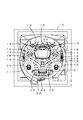
図1はパチンコ機の遊技盤10の正面図であり、いわゆる第1種パチンコ機と呼ばれるものである。このパチンコ機本体の構成は公知の技術にしたがっているので図示および説明は省略する。
図1に示すように、遊技盤10は、周囲をガイドレール11により円形状に外囲され、このガイドレール11に囲まれた領域が遊技領域12となる。この遊技領域12には複数の釘13がほぼ全域にわたって設けられており、この釘13によって遊技領域12に発射された遊技球を任意の位置に誘導することができる。遊技領域12の略中央部にはセンター役物14が装着されており、このセンター役物14の周囲には、ランプ風車15、15、風車16、16、図柄始動用ゲート17、17、サイドランプ18、18、始動口19が配設されている。
【0018】
始動口19の左右には肩入賞口20、20が配設されており、始動口19の下方には入賞装置21が装着されている。この入賞装置21は、中央に大入賞口22を設けており、その両端に袖入賞口23、23が設けられている。そして、入賞装置21の下方、ガイドレール11の最下部にはアウト口24が配設されている。
【0019】
次に、本発明に係る遊技部品の代表例である肩入賞口20、図柄始動用ゲート17の構造について説明をする。図2〜図4は肩入賞口20の構造を示す図であり、図5〜図7は図柄始動用ゲート17の構造を示す図である。
まず、図2〜図4にしたがって、肩入賞口20の構造について説明すると、図2は肩入賞口20の正面斜視図、図3は同裏面斜視図、図4は同縦断面図である。
【0020】
図に示すように、肩入賞口20は遊技盤10に螺設するための部材となる取付基板25にて各部を支持する構造である。まず、取付基板25には、適宜の個所に遊技盤10に螺設するための取付孔26が穿設されており、略中央部には開口部27を開口する。この開口部27には、裏面から球受部材28が挿通されており、球受部材28は開口部27内を前後方向に摺動可能となっている。
【0021】
球受部材28の上部には、遊技球が入球する球入口29が形成されると共に、その下方に連通状に入球した遊技球を後方へ導くための球誘導樋30が一体に延長形成されている。また、球受部材28の裏面上部両端には、球受部材28が取付基板25の前方へ脱落しないようにするためのL字状の脱落防止片31が突設している。そして、球受部材28の外側下部には、球入口29が取付基板25の前方に突出した状態を維持するための保持機構32が設けられている。この保持機構32は、球受部材28の下部外側やや中央から後方側に延出された弾性片32aが設けられており、この弾性片32aは固定点32bを支点として揺動変位可能であり、下面には台形状の係合突起32cが設けられている。
【0022】
球受部材28の下方には、表面構成部材33が取付けられており、この表面構成部材33は着色された樹脂で形成され、装飾効果を発揮するものである。また、この表面構成部材33を透光性を有する樹脂などで形成し、裏面より光源、即ちランプなどで照射すればより一層の装飾効果を発揮することもできる。
【0023】
次に、図5〜図7にしたがって、図柄始動用ゲート17の構造について説明をする。図5は図柄始動用ゲート17の正面斜視図、図6は同裏面斜視図、図7は同縦断面図である。
図に示すように、図柄始動用ゲート17は遊技盤10に螺設するための部材となる取付基板34にて各部を支持する構造である。この取付基板34には、適宜の個所に遊技盤10に螺設するための取付孔35が穿設されており、中央部には開口部36を開口する。この開口部36には、裏面から球通過部材37が挿通されており、球通過部材37は開口部36内を前後方向に摺動可能となっている。
【0024】
球通過部材37の前方部分には、遊技球が通過する球通過口38が形成されており、後端面には、通過した遊技球を検出する遊技球検出スイッチ(図示せず)を挿通するための貫通孔39が設けられている。また、球通過部材37の右側面後方には、球通過部材37が取付基板34の前方へ脱落しないようにするためのL字状の脱落防止片40が突設している。また、球通過部材37の右側面前方には、球通過口38が取付基板34の前方に突出した状態を維持するための保持機構41が設けられている。この保持機構41は、球通過部材37の右側面やや中央から後方側に延出された弾性片41aが設けられており、この弾性片41aは固定点41bを支点として揺動変位可能であり、側面には台形状の係合突起41cが設けられている。
【0025】
次に、上記で説明した構造の肩入賞口20の球受部材28、図柄始動用ゲート17の球通過部材37の押入方法について、図8にしたがって説明をする。なお、肩入賞口20の球受部材28の押入方法も図柄始動用ゲート17の球通過部材37の押入方法も同様であるので、ここでは、図柄始動用ゲート17を代表例として説明をする。
【0026】
図8は、図柄始動用ゲート17を遊技盤10に取付けた状態の正面斜視図であり、(a)は球通過部材37が通常状態、(b)は球通過部材37を押入したときの状態の図である。図に示すように、図柄始動用ゲート17は取付基板34に適宜設けられた取付孔35に挿通されるビス等により、遊技盤10に螺設されている。
【0027】
球通過部材37が通常の状態では(a)に示すように、前方部分に形成される球通過口38を取付基板34の表面から突出した状態に位置している。この状態では、球通過口38の上方に突設している釘13、13の先端の高さと球通過部材37の先端部の高さはほぼ同じ高さとなっている。また、このときは球通過部材37の右側面に設けられる保持機構41の係合により、球通過部材37の位置は保持されているので、遊技球が球通過口38を通過する際の衝撃などで球通過部材37の位置が移動するようなことがない。したがって、球通過部材37の位置が移動することによる球通過口38の大きさが変化するということがないの
で、球詰まりなどが発生することがない。
【0028】
上記の状態から、釘調整を行なうときには、球通過部材37を矢印P方向に押すことにより、(b)に示すように、球通過部材37を取付基板34の開口部36内を摺動しながら押入することができる。この球通過部材37を押入した状態では、球通過部材37の先端部の高さは釘13、13の先端の高さよりもはるかに低くなる。したがって、この状態で釘調整をおこなえば、釘13、13を必ず殴打することになるので、目測を誤るようなことがあっても球通過部材37を殴打して損傷させるようなことがない。また、釘調整を行なう店員が初心者であっても、球通過部材37が、このような状態であれば釘調整を容易に行なうことができると共に、短時間で、しかも正確に釘調整ができるという優れた効果を発揮する。また、球通過部材37を押入するときには、手で押すという簡単な操作で保持機構41の係合を解除し、押入することができるので作業性が良い。
【0029】
次に、保持機構41の作用について、図9に従って説明をする。図9は、図柄始動用ゲート17の横断面図で、(a)は球通過部材37が通常の状態、(b)は球通過部材37が押入中の状態、(c)は球通過部材37を押入した状態の図である。
【0030】
(a)に示すように、球通過部材37が通常の状態では、保持機構41の弾性片41aの弾性力により、係合突起41cが開口部36の縁部に当接するように係合している。この状態では球通過部材37は、後方の移動を係合突起41cと開口部36の縁部の係合により規制され、前方への移動を脱落防止片40により規制されることにより、定位置で保持されている。したがって、球通過部材37に遊技球の衝撃などが加わっても、球通過部材37の位置が移動するようなことがない。
【0031】
(a)の状態から球通過部材37を矢印P方向に押すと、(b)に示すように弾性片41aに固定点41bを中心として弓状に内側に弾性変形させようとする力が発生する。これは、係合突起41cと開口部36の縁部が当接している係合突起41cの当接面は傾斜面となっており、弾性片41aの弾性力よりも矢印P方向の力が大きくなると、弾性片41aを弾性変形させながら係合突起41cが開口部36を摺動することになる。したがって、係合突起41cと開口部36の縁部との係合が解除され、球通過部材37が矢印P方向に開口部36を摺動しながら移動する。
【0032】
そして、係合突起41cが開口部36を通過すると、(c)に示すように、弾性片41aは、自己の弾性力により元の位置に復帰し、球通過部材37の押入が完了する。また、この状態から球通過部材37を通常の状態に戻すためには、球通過部材37を矢印R方向に引っ張ることで、上記で説明した作用とは逆の作用により、係合突起41cが開口部36の前面までくると、弾性片41aが自己の弾性力により元の位置に復帰し、係合突起41cと開口部36の縁部が当接し、係合することになるので、球通過部材37を定位置に保持することができる。また、球通過部材37を引っ張りすぎるようなことがあっても、脱落防止片40が設けられているので開口部36内から球通過部材37が脱落するようなことはない。
【0033】
以上説明したように、本発明によれば、球受部材あるいは球通過部材を押入することができるようにしたので、釘調整時などに遊技部品を破損するようなことがない。さらに、初心者であっても正確に釘調整ができると共に、作業時間も短縮することができるという優れた効果を発揮するものである。
【図面の簡単な説明】
【図1】 実施例のパチンコ機の遊技盤の正面図である。
【図2】 実施例の肩入賞口の正面斜視図である。
【図3】 実施例の肩入賞口の裏面斜視図である。
【図4】 実施例の肩入賞口の縦断面図である。
【図5】 実施例の図柄始動用ゲートの正面斜視図である
【図6】 実施例の図柄始動用ゲートの裏面斜視図である。
【図7】 実施例の図柄始動用ゲートの縦断面図である。
【図8】 実施例の図柄始動用ゲートを遊技盤に取付けた斜視図で、(a)は球通過部材が通常状態の図であり、(b)は球通過部材が押入状態の図である。
【図9】 実施例の図柄始動用ゲートの横断面図で、(a)は球通過部材が通常状態の図であり、(b)は球通過部材が押入中の状態の図であり、(c)は球通過部材が押入状態の図である。
【符号の説明】
10…遊技盤、11…ガイドレール、12…遊技領域、13…釘、
14…センター役物、15…ランプ風車、16…風車、17…図柄始動用ゲート、
18…サイドランプ、19…始動口、20…肩入賞口、21…入賞装置、
22…大入賞口、23…袖入賞口、24…アウト口、25…取付基板、
26…取付孔、27…開口部、28…球受部材、29…球入口、
30…球誘導樋、31…脱落防止片、32…保持機構、32a…弾性片、
32b…固定点、32c…係合突起、33…表面構成部材、34…取付基板、
35…取付孔、36…開口部、37…球通過部材、38…球通過口、
39…貫通孔、40…脱落防止片、41…保持機構、41a…弾性片、
41b…固定点、41c…係合突起。[0001]
BACKGROUND OF THE INVENTION
The present invention relates to a game component disposed on a game board surface.
[0002]
[Prior art]
Conventionally, game parts arranged on the game board surface include a winning chucker and a symbol starting gate as typical examples. These gaming parts are integrally formed with a ball receiving part for entering a game ball or a ball passing part for passing a game ball on the front surface of a mounting board for attaching to the game board. Further, it is screwed with screws or the like.
[0003]
[Problems to be solved by the invention]
By the way, in these conventional game parts, when adjusting a nail, it was often damaged accidentally. Specifically, in the game area formed on the game board, a plurality of nails for guiding the game ball in all directions protrudes over almost the entire area, and these nails are densely arranged around the game parts. And projecting. The nail projecting around the gaming part has an important effect in changing the winning rate or passing rate of the gaming ball to the ball receiving portion or passing portion of the gaming component. It is necessary to adjust these nails to change.
[0004]
When adjusting these nails, it is very important to adjust the two nails (hereinafter referred to as life nails) directly above both ends of the ball receiving portion or the ball passing portion. For example, game balls can easily pass between life nails, so that the winning rate or passing rate for game parts can be increased. Conversely, if the ball is narrowed, game balls are less likely to pass between life nails. The winning rate or passing rate can be lowered. Therefore, it is necessary to adjust this life nail frequently according to the business policy of the amusement store.
[0005]
On the other hand, this nail adjustment is performed by a store clerk at a game store directly hitting the nail with a hammer or the like and adjusting the projecting angle of the nail. Therefore, when adjusting the nail immediately above the ball receiving portion or the ball passing portion of a game part such as a life nail, it is formed on the protrusion part of the game part, that is, the game part, without hitting the nail if mistakenly measured. The ball receiving part or the ball passing part is hit and the game parts are damaged.
[0006]
In addition, skilled techniques are necessary for adjusting the nail, and when the store clerk performing the nail adjustment is a beginner, the ball receiving part or the ball passing part becomes an obstacle when adjusting the life nail, It cannot be adjusted accurately, and the winning rate or passing rate cannot be adjusted to the target value. In addition, it took too much time to adjust the nail.
[0007]
Therefore, the present invention has been made in view of the circumstances as described above, and its purpose is not to accidentally damage gaming parts during nail adjustment, and even a beginner can accurately adjust the nail. It is another object of the present invention to provide a game component for a ball game machine that can reduce the time required for nail adjustment.
[0008]
[Means for Solving the Problems and Effects of the Invention]
The present invention has been proposed in view of the above problems, and the gaming component of the ball game machine according to
[0009]
An opening is formed in the game component mounting substrate, and a ball receiving member that forms a ball receiving portion into which a game ball can enter or a ball passing member that forms a ball passing portion through which a game ball can pass is inserted into the opening. Since the ball receiving portion of the ball receiving member or the ball passing portion of the ball passing member can be moved in and out, the ball receiving portion or the ball passing portion is pushed in from the front surface of the mounting substrate when adjusting the nail. By doing so, it can be made lower than the height of the tip of the nail. Therefore, even if the measurement is mistaken when hitting the nail with a hammer or the like, even if the tip of the nail is hit, the game component is not hit directly. That is, it is possible to prevent the gaming parts from being damaged during the nail adjustment.
[0010]
Furthermore, even if a beginner makes a nail adjustment, since the ball receiving part or the ball passing part can be pushed in from the front surface of the mounting substrate, by pushing the ball receiving part or the ball passing part to a position that does not get in the way, Nail adjustment can be performed accurately. In addition, since the nail adjustment can be performed as quickly as the ball receiving portion or the ball passing portion does not get in the way, the working time can be shortened.
[0012]
The game component includes holding means for holding the ball receiving portion of the ball receiving member or the ball passing portion of the ball passing member protruding from the front surface of the mounting board. There is no possibility that the ball receiving part or the ball passing part moves due to an impact or the like when the game ball enters or passes through the receiving part or the ball passing part, and the game is not hindered.
[0013]
Since the holding means is configured to be released by manually pressing the ball receiving portion or the ball passing portion, it is possible to adjust the nail in a short time without requiring any tools. Demonstrate.
[0014]
In addition, the game component of the ball game machine according to
[0015]
Since the holding means is configured so that it can be fixed by a simple operation of manually pulling out the inserted ball receiving portion or the ball passing portion, when the game ball wins or passes due to a fixing error or the like, Ball clogging does not occur at the receiving part or the ball passing part.
[0016]
DETAILED DESCRIPTION OF THE INVENTION
Next, embodiments of the present invention will be described more specifically with reference to preferred examples. The embodiments of the present invention are not limited to the following examples, and it goes without saying that various forms can be adopted as long as they belong to the technical scope of the present invention.
[0017]
【Example】
FIG. 1 is a front view of a
As shown in FIG. 1, the
[0018]
Shoulder winning
[0019]
Next, the structure of the
First, the structure of the
[0020]
As shown in the figure, the
[0021]
A
[0022]
A surface constituting member 33 is attached below the
[0023]
Next, the structure of the
As shown in the figure, the
[0024]
A
[0025]
Next, a method of pushing in the
[0026]
FIG. 8 is a front perspective view of the state where the
[0027]
In a normal state, the
[0028]
When adjusting the nail from the above state, by pushing the
[0029]
Next, the operation of the
[0030]
As shown in (a), when the
[0031]
When the
[0032]
When the engaging protrusion 41c passes through the
[0033]
As described above, according to the present invention, since the ball receiving member or the ball passing member can be pushed in, there is no possibility of damaging the game component when adjusting the nail. In addition, even a beginner can accurately adjust the nail and can shorten the working time.
[Brief description of the drawings]
FIG. 1 is a front view of a game board of a pachinko machine according to an embodiment.
FIG. 2 is a front perspective view of a shoulder opening according to an embodiment.
FIG. 3 is a rear perspective view of a shoulder winning opening according to an embodiment.
FIG. 4 is a longitudinal sectional view of a shoulder winning opening according to an embodiment.
FIG. 5 is a front perspective view of the symbol starting gate of the embodiment. FIG. 6 is a rear perspective view of the symbol starting gate of the embodiment.
FIG. 7 is a longitudinal sectional view of a symbol starting gate according to the embodiment.
FIG. 8 is a perspective view in which the symbol starting gate of the embodiment is attached to the game board, (a) is a view of the ball passage member in a normal state, (b) is a view of the ball passage member in the pushed state. .
FIGS. 9A and 9B are cross-sectional views of the symbol starting gate of the embodiment, in which FIG. 9A is a diagram of a ball passing member in a normal state, and FIG. 9B is a diagram of a state in which the ball passing member is being pushed in; c) is a view showing a state in which the ball passing member is pushed.
[Explanation of symbols]
10 ... Game board, 11 ... Guide rail, 12 ... Game area, 13 ... Nails,
14 ... Center role, 15 ... Ramp windmill, 16 ... Windmill, 17 ... Design start gate,
18 ... side lamp, 19 ... start-up port, 20 ... shoulder winning port, 21 ... winning device,
22 ... Large winning opening, 23 ... Sleeving winning opening, 24 ... Out opening, 25 ... Mounting board,
26 ... mounting hole, 27 ... opening, 28 ... ball receiving member, 29 ... ball inlet,
30 ... Ball guide rod, 31 ... Fall-off prevention piece, 32 ... Holding mechanism, 32a ... Elastic piece,
32b ... fixing point, 32c ... engagement protrusion, 33 ... surface constituent member, 34 ... mounting substrate,
35 ... mounting hole, 36 ... opening, 37 ... sphere passage member, 38 ... sphere passage port,
39 ... Through-hole, 40 ... Drop-off prevention piece, 41 ... Holding mechanism, 41a ... Elastic piece,
41b ... fixing point, 41c ... engagement protrusion.
Claims (2)
前記遊技部品は遊技盤に取着するための取付基板を有し、該取付基板に開口部を開設すると共に、該開口部内には、前記球受部材あるいは前記球通過部材を挿通して設け、前記球受部材の球受部あるいは前記球通過部材の球通過部を前記取付基板の前面から出入可能とし、さらに、前記球受部材の球受部あるいは前記球通過部材の球通過部が前記取付基板の前面に突出した状態を保持する保持手段を備え、該保持手段は前記球受部材の球受部あるいは前記球通過部材の球通過部を手で押入することにより解除されることを特徴とする弾球遊技機の遊技部品。From the game board, a ball receiving member formed with a ball receiving portion into which a game ball can enter or a ball passing member formed with a ball passing portion through which a game ball can pass from the game board is formed in the game area formed on the game board. A projecting game part and a nail arranged immediately above the game part, and changing the angle of the nail, the winning rate of the game ball to the ball receiving member or the passing rate of the game ball to the passing member changes. In a ball game machine,
The game part has a mounting substrate for attaching to the game board, while establishing an opening in a substrate with said mounting, the opening portion, provided through the ball receiving member or the ball passing member, The ball receiving portion of the ball receiving member or the ball passing portion of the ball passing member can be moved in and out from the front surface of the mounting substrate, and the ball receiving portion of the ball receiving member or the ball passing portion of the ball passing member is attached to the mounting plate. And holding means for holding the protruding state on the front surface of the substrate, the holding means being released by manually pushing in the ball receiving portion of the ball receiving member or the ball passing portion of the ball passing member. Game parts for a ball game machine to play.
前記保持手段は前記球受部材の球受部あるいは前記球通過部材の球通過部を引出すことにより固定されることを特徴とする弾球遊技機の遊技部品。In the game part of the ball game machine according to claim 1,
The game part of a ball game machine, wherein the holding means is fixed by pulling out a ball receiving part of the ball receiving member or a ball passing part of the ball passing member.
Priority Applications (1)
| Application Number | Priority Date | Filing Date | Title |
|---|---|---|---|
| JP31126199A JP4448912B2 (en) | 1999-11-01 | 1999-11-01 | Game parts for ball game machines |
Applications Claiming Priority (1)
| Application Number | Priority Date | Filing Date | Title |
|---|---|---|---|
| JP31126199A JP4448912B2 (en) | 1999-11-01 | 1999-11-01 | Game parts for ball game machines |
Publications (3)
| Publication Number | Publication Date |
|---|---|
| JP2001129171A JP2001129171A (en) | 2001-05-15 |
| JP2001129171A5 JP2001129171A5 (en) | 2007-02-08 |
| JP4448912B2 true JP4448912B2 (en) | 2010-04-14 |
Family
ID=18015023
Family Applications (1)
| Application Number | Title | Priority Date | Filing Date |
|---|---|---|---|
| JP31126199A Expired - Lifetime JP4448912B2 (en) | 1999-11-01 | 1999-11-01 | Game parts for ball game machines |
Country Status (1)
| Country | Link |
|---|---|
| JP (1) | JP4448912B2 (en) |
Families Citing this family (3)
| Publication number | Priority date | Publication date | Assignee | Title |
|---|---|---|---|---|
| JP2010273998A (en) * | 2009-05-29 | 2010-12-09 | Okumura Yu-Ki Co Ltd | Pinball game machine |
| JP5626156B2 (en) * | 2011-08-02 | 2014-11-19 | 奥村遊機株式会社 | Game machine |
| JP6577418B2 (en) * | 2016-06-15 | 2019-09-18 | 株式会社ニューギン | Game machine |
-
1999
- 1999-11-01 JP JP31126199A patent/JP4448912B2/en not_active Expired - Lifetime
Also Published As
| Publication number | Publication date |
|---|---|
| JP2001129171A (en) | 2001-05-15 |
Similar Documents
| Publication | Publication Date | Title |
|---|---|---|
| JP3927216B2 (en) | Game machine operating device and portable game machine | |
| JP4579009B2 (en) | Game machine | |
| JP4244392B2 (en) | Game machine | |
| JP4467465B2 (en) | Game board and game machine using the same | |
| JP2002028329A (en) | Pachinko game machine | |
| JP4448912B2 (en) | Game parts for ball game machines | |
| JPS636229B2 (en) | ||
| JP4842556B2 (en) | Game machine bullet launcher | |
| JPH0648762U (en) | Return ball blocking member for pachinko machines | |
| JP5706150B2 (en) | Sphere launch passage | |
| JP3017551U (en) | Pachinko machine electric winning device | |
| JP5829738B2 (en) | Sphere launch passage | |
| JPH07289700A (en) | Prize-winning device for pachinko machine | |
| JP2019111118A (en) | Winning device of pinball game machine | |
| JP2001218903A (en) | Pinball game machine | |
| CN111659101B (en) | Game disc | |
| US7918459B1 (en) | Thrower for game machine | |
| JP4475612B2 (en) | Bullet ball machine | |
| JPS5825478B2 (en) | Baseball board that can display pitching speed | |
| US5716049A (en) | Pinball machine target assembly | |
| JP4066151B2 (en) | Game machine | |
| JP4258599B2 (en) | Pachislot machines and pachinko machines | |
| JP2569933Y2 (en) | Pachinko machine prize receiving device | |
| JP4701444B2 (en) | Game machine | |
| JP3480907B2 (en) | Ball backflow prevention device for ball game machines |
Legal Events
| Date | Code | Title | Description |
|---|---|---|---|
| A521 | Written amendment |
Free format text: JAPANESE INTERMEDIATE CODE: A523 Effective date: 20061012 |
|
| A621 | Written request for application examination |
Free format text: JAPANESE INTERMEDIATE CODE: A621 Effective date: 20061012 |
|
| A131 | Notification of reasons for refusal |
Free format text: JAPANESE INTERMEDIATE CODE: A131 Effective date: 20090930 |
|
| A977 | Report on retrieval |
Free format text: JAPANESE INTERMEDIATE CODE: A971007 Effective date: 20090930 |
|
| A521 | Written amendment |
Free format text: JAPANESE INTERMEDIATE CODE: A523 Effective date: 20091110 |
|
| TRDD | Decision of grant or rejection written | ||
| A01 | Written decision to grant a patent or to grant a registration (utility model) |
Free format text: JAPANESE INTERMEDIATE CODE: A01 Effective date: 20091207 |
|
| A01 | Written decision to grant a patent or to grant a registration (utility model) |
Free format text: JAPANESE INTERMEDIATE CODE: A01 |
|
| A61 | First payment of annual fees (during grant procedure) |
Free format text: JAPANESE INTERMEDIATE CODE: A61 Effective date: 20091207 |
|
| R150 | Certificate of patent or registration of utility model |
Ref document number: 4448912 Country of ref document: JP Free format text: JAPANESE INTERMEDIATE CODE: R150 Free format text: JAPANESE INTERMEDIATE CODE: R150 |
|
| FPAY | Renewal fee payment (event date is renewal date of database) |
Free format text: PAYMENT UNTIL: 20130205 Year of fee payment: 3 |
|
| S531 | Written request for registration of change of domicile |
Free format text: JAPANESE INTERMEDIATE CODE: R313531 |
|
| R350 | Written notification of registration of transfer |
Free format text: JAPANESE INTERMEDIATE CODE: R350 |
|
| R250 | Receipt of annual fees |
Free format text: JAPANESE INTERMEDIATE CODE: R250 |
|
| R250 | Receipt of annual fees |
Free format text: JAPANESE INTERMEDIATE CODE: R250 |
|
| EXPY | Cancellation because of completion of term |