JP4448491B2 - Compensator for synchronous sampling time-based servo system - Google Patents
Compensator for synchronous sampling time-based servo system Download PDFInfo
- Publication number
- JP4448491B2 JP4448491B2 JP2005360532A JP2005360532A JP4448491B2 JP 4448491 B2 JP4448491 B2 JP 4448491B2 JP 2005360532 A JP2005360532 A JP 2005360532A JP 2005360532 A JP2005360532 A JP 2005360532A JP 4448491 B2 JP4448491 B2 JP 4448491B2
- Authority
- JP
- Japan
- Prior art keywords
- tape
- tape head
- output value
- head position
- position signal
- Prior art date
- Legal status (The legal status is an assumption and is not a legal conclusion. Google has not performed a legal analysis and makes no representation as to the accuracy of the status listed.)
- Expired - Fee Related
Links
Images


Classifications
-
- G—PHYSICS
- G11—INFORMATION STORAGE
- G11B—INFORMATION STORAGE BASED ON RELATIVE MOVEMENT BETWEEN RECORD CARRIER AND TRANSDUCER
- G11B5/00—Recording by magnetisation or demagnetisation of a record carrier; Reproducing by magnetic means; Record carriers therefor
- G11B5/48—Disposition or mounting of heads or head supports relative to record carriers ; arrangements of heads, e.g. for scanning the record carrier to increase the relative speed
- G11B5/58—Disposition or mounting of heads or head supports relative to record carriers ; arrangements of heads, e.g. for scanning the record carrier to increase the relative speed with provision for moving the head for the purpose of maintaining alignment of the head relative to the record carrier during transducing operation, e.g. to compensate for surface irregularities of the latter or for track following
- G11B5/584—Disposition or mounting of heads or head supports relative to record carriers ; arrangements of heads, e.g. for scanning the record carrier to increase the relative speed with provision for moving the head for the purpose of maintaining alignment of the head relative to the record carrier during transducing operation, e.g. to compensate for surface irregularities of the latter or for track following for track following on tapes
-
- G—PHYSICS
- G11—INFORMATION STORAGE
- G11B—INFORMATION STORAGE BASED ON RELATIVE MOVEMENT BETWEEN RECORD CARRIER AND TRANSDUCER
- G11B15/00—Driving, starting or stopping record carriers of filamentary or web form; Driving both such record carriers and heads; Guiding such record carriers or containers therefor; Control thereof; Control of operating function
- G11B15/675—Guiding containers, e.g. loading, ejecting cassettes
- G11B15/68—Automatic cassette changing arrangements; automatic tape changing arrangements
- G11B15/6845—Automatic cassette changing arrangements; automatic tape changing arrangements with rotatable magazine
- G11B15/687—Automatic cassette changing arrangements; automatic tape changing arrangements with rotatable magazine the cassettes being arranged in multiple levels
- G11B15/688—Automatic cassette changing arrangements; automatic tape changing arrangements with rotatable magazine the cassettes being arranged in multiple levels the cassettes being transferred to a fixed recorder or player using a moving carriage
Landscapes
- Adjustment Of The Magnetic Head Position Track Following On Tapes (AREA)
- Feedback Control In General (AREA)
- Automatic Tape Cassette Changers (AREA)
Description
ここでの開示は、サーボ制御システムに関する。 The disclosure herein relates to servo control systems.
同期サンプリング時間基準サーボシステムのための補償器を提供することである。 It is to provide a compensator for a synchronous sampling time reference servo system.
本発明の方法は、テープヘッドに沿って磁気テープを動かすための基本テープ速度を有し、該基本テープ速度に比例する第1サンプル周波数で該テープヘッドから第1テープヘッド位置信号を生成するようになったテープドライブを作動させる方法であって、該方法が、該第1サンプル周波数に同期した該第1テープヘッド位置信号を処理するためのものであって、第1クロスオーバー周波数における最大位相応答を有する補償器を含む制御システムを用いて該テープヘッドの位置を制御するステップと、該第1サンプル周波数に同期した割り込み信号を処理システムに与えるステップと、を含み、該処理システムが該割り込み信号を受け取るのに応答して、該処理システムが、該第1クロスオーバー周波数で該最大位相応答を生成する出力値h(k)を与えるようにすることを特徴とする。 The method of the present invention has a base tape speed for moving the magnetic tape along the tape head and generates a first tape head position signal from the tape head at a first sample frequency proportional to the base tape speed. A method of operating a tape drive configured to process the first tape head position signal synchronized to the first sample frequency, wherein the maximum phase at the first crossover frequency is Controlling the position of the tape head using a control system including a compensator having a response, and providing an interrupt signal synchronized to the first sample frequency to the processing system, the processing system including the interrupt In response to receiving a signal, the output of the processing system produces the maximum phase response at the first crossover frequency. Characterized in that so as to provide the h (k).
以下の実施形態は、図面を参照しながら説明される。説明は、実施形態と組み合わせて進められるが、特許請求の範囲の請求項によって定められる精神及び範囲内に含まれるような代案、変更、及び均等物を含むことを意図されることが当業者には認識されるであろう。 The following embodiments will be described with reference to the drawings. Although the description proceeds in conjunction with the embodiments, those skilled in the art will appreciate that alternatives, modifications, and equivalents are intended to be included within the spirit and scope as defined by the claims. Will be recognized.
図1は、データストレージ・テープドライブにおけるサーボシステムに従うトラックのためのサーボ制御システム100の一部のブロック図である。ここで説明された実施形態と共に用いられる時間基準サーボ信号を用いるサーボシステムに従うトラックの1つの実装の説明が、引用によりここに組み入れられる米国特許第6,021,013号に開示されている。以下の詳細な説明は、時間基準サーボシステムを有する磁気テープドライブについて進められるが、説明される実施形態は、時間基準サーボシステムを有する磁気テープドライブに限定されることを意図されるものではないことが当業者には認識されるであろう。むしろ、実施形態は、あらゆるタイプのサーボシステムを有するあらゆるテープドライブに使用可能な光学テープ又は他のテープと共に用いることができる。
FIG. 1 is a block diagram of a portion of a
図1を参照すると、サーボセンサ及び前置増幅器171によってテープヘッド信号が感知されて、ヘッド・テープ・インターフェース172からのサーボ信号150が生成される。ヘッド・テープ・インターフェース172は、図2を参照すると良く理解することができる。図2は、例示的なテープ移送システム200のテープパスを示す図である。図2に示されたテープ移送システム200は、或る長さのテープ206が巻かれる第1テープリール204を収容しているテープ・カートリッジ202を受け入れる。テープ移送システム200は、第2テープリール208、少なくとも1つのテープヘッド210及びガイドローラ212を含む。カートリッジ202がテープ移送システム200に挿入されたときに、テープ206がローラ212の周りに自動的に通され、テープヘッド210を横切って第2テープリール208上に通される。モータ(図示せず)が、リール204及び208に作動的に結合され、テープ206を、テープに/テープから公知の形式で情報を読み取り/書き込むテープヘッド210を横切るようにテープ速度Vで引っ張る。モータはまた、早送り及び巻き戻し作動においてテープ206を1つのリールから別のリールに高速で動かす。モータは、第1テープリール204及び第2テープリール208に直接結合することができ、又はリールとモータとの間に機械的駆動システムを存在させることができる。直接結合されるのか又は機械的駆動システムを通じて結合されるのかといった結合形式が、モータとテープリールとの間の機械的関係性を決める。機械的駆動システムは、例えば、ギア、ベルト、滑車、クラッチなどとすることができる。全てのテープ作動は、テープ206がいずれかの方向に移動するようにして行われる。したがって、第1テープリール204又は第2テープリール208のいずれかは、テープ206の方向に応じて、繰り出しリール又は巻取りリールとして働くことができる。図2においては、カートリッジ202内の第1テープリール204は、テープ繰り出しリールとして働くことが示され、一方、第2テープリール208は、巻取りリールとして働くことが示される。この開示においては、「繰り出しリール」という用語は、現在のところ繰り出しリールとして作動するリールのことをいい、「巻取りリール」という用語は、現在のところ巻取りリールとして作動するリールのことをいう。さらに、「繰り出しモータ」及び「巻取りモータ」という用語は、それぞれ繰り出しリール及び巻取りリールに作動的に結合されたモータのことをいう。図2に示されたタイプのテープ移送システム200は、単に図示することを目的とするものであり、ここで説明された実施形態は、他のタイプの移送システムと共に用いてもよい。
Referring to FIG. 1, a tape head signal is sensed by a servo sensor and preamplifier 171 to generate a
図1を参照すると、サーボセンサ及び前置増幅器171から導出されたサーボ信号150は、ヘッド・テープ・インターフェース172において磁気テープ(すなわちテープ206)がテープ速度Vでテープヘッド(すなわちテープヘッド210)に沿って動いた結果として生じる。サーボセンサ及び前置増幅器171からのサーボ信号150は、ディジタルサンプラ173によってサンプリングされ、ディジタルフィルタ174によってフィルタされて、ピーク検出器175に与えられる。サーボセンサ及び前置増幅器171からのサーボ信号150は、テープ速度と共に変化するサンプリング速度でディジタルサンプラ173によってサンプリングされる。ディジタルサンプラ173によるサーボ信号150のサンプリングによって、例えば中央処理装置又はディジタルフィルタといったディジタル処理装置による処理に適したサーボ信号150のディジタル表現が生成される。ディジタルフィルタ174が、ディジタルサンプラ173によって生成されたサーボ信号150のディジタル表現を受け取り、フィルタリング動作を行ってサーボ信号150からの望ましくないノイズを除去し、フィルタリングされたサーボ信号を生成する。
Referring to FIG. 1, the
図3は、ディジタルフィルタ174及び/又は補償器185(図1)に用いられる有限インパルス応答(FIR)ディジタルフィルタ300の一例を示す。ディジタルフィルタ300は、コード、論理、ハードウェア論理として実装することができる(例えば、集積回路チップ、プログラマブル・ゲート・アレイ(PGA)、特定用途向け集積回路(ASIC)など)。他のタイプのディジタルフィルタを用いることもできることを当業者であれば理解するであろう。FIRディジタルフィルタ300は、サンプリングバージョンのサーボ信号150を受け取る入力305と、ピーク検出器175に対するサーボ信号150のフィルタリングバージョンを生成する出力330とを有する。フィルタは、一連の時間遅延要素Z−1306と、ディジタルフィルタ係数C0、C 1 、C2、C3・・・CN−2及びCN−1を乗算するための乗算器310と、加算器320とを含む。一実施形態においては、FIRディジタルフィルタ300は、17段のディジタルフィルタを含み、結果としてN=17であるが、Nは使用されるシステム及び望まれる性能に応じて変化することができる。各テープ速度の水平方向中心点に関して対称な各平均サーボ信号150の一部の等間隔な17のサンプルを得ることによって、ディジタルフィルタ174において用いるための17のディジタルフィルタ係数C0、C 1 、C2、C3・・・C15及びC16が求められる。
FIG. 3 illustrates an example of a finite impulse response (FIR)
図1を参照すると、ディジタルフィルタ174は、処理要素190によって制御される。処理要素190は、中央処理装置(CPU)と、代替的ディジタル処理装置と、ASICと、専用論理回路など、又はこれらの組み合わせを含むことができる。テープ速度センサ191が、テープ速度を感知し、処理要素190に与える。処理要素190は、ディジタルフィルタ174にディジタルフィルタ係数を与え、テープ速度の状態に応じてディジタルフィルタ174をイネーブルにし又はディスエーブルにする。ディジタルフィルタ174は、サーボ信号150のフィルタリングバージョンをピーク検出器175に与える。ピーク検出器175は、フィルタリング・サーボ信号150のピークのときの位置を判断する。時間基準変換器176は、ピーク検出器175からの出力を受信し、補償器185(図1)に入力するために信号をテープヘッド位置信号に変換する。好ましい実施形態においては、ピーク検出器175からの出力信号は、プラス方向に向かう遷移(前縁)においては高くなり、マイナス方向に向かう遷移においては低くなり、時間基準変換器176が2つの極性間を区別することを可能にする。前述のように、時間基準変換器176によってテープヘッド位置信号が生成される。時間基準変換器176の機能は、サーボ制御システムの残りの部分においてテープヘッド位置信号を利用できるようにするために必要な計算を行うことである。時間基準変換器176は、テープヘッド位置信号を導出するために、ピーク間の時間を正確に計測するための基準として水晶発振器を用いることができる。時間基準変換器176は、サーボ制御システム100の残りの部品にテープヘッド位置信号195と割り込み信号193を与える。ひとまとめに、要素171、173、174、175、176、190及び191は、ここではサーボ信号プロセッサ192と呼ばれる。サーボ信号プロセッサ192は、テープがテープ速度Vでテープヘッドに沿って移動する際にテープヘッドから得られた信号を処理することによって、テープヘッド位置信号195と割り込み信号193を生成する。システムの最適な性能のために、時間が一致し、ヘッド・テープ・インターフェース172においてテープヘッドから信号が生成された時刻から最小限の遅延を有するテープヘッド位置信号195及び割り込み信号193が与えられる。
Referring to FIG. 1,
テープヘッド位置信号195は、コンパレータ178によって基準信号177と比較されて、ライン179上で、ヘッドと、定められたサーボトラックに関連する所望の位置との間の位置誤差が判断され、それは「位置誤差信号」すなわち「PES」と呼ばれる。コンパレータ178は、処理システム(すなわち、図6の処理システム600)の使用によって補償器185(図1)において実装することができる。テープヘッド位置信号195は、テープに対するテープヘッドの相対的な横方向位置を示す値を与える。位置誤差信号すなわちPESは、テープに対するテープヘッドの所望の横方向位置とテープに対するテープヘッドの実際の横方向位置との間の差を示す値を与える。ここでの開示のために、テープに対するテープヘッドの横方向位置は、テープ移送システム200によるテープの移動に対して垂直な方向の、テープに対するテープヘッドの位置を意味する。
The tape
テープに対してテープヘッド(すなわちテープヘッド210)を位置決めするために複合アクチュエータが用いられる。テープドライブにおける複合アクチュエータの使用の例は、「Servo Control of a Coarse Actuator」と題する特許文献1に記載されている。典型的な複合アクチュエータにおいては、微動アクチュエータ180は、1つ又は複数のデータトラックの中央においてテープヘッドのデータヘッド(1つ又は複数)を位置決めするために、PESによって決まるトラックガード外乱に従う。特定の実施形態においては、微動アクチュエータ180は、幅広い帯域応答をもたらす比較的小さい質量を有し、それにより高い周波数外乱に従うことができる。特定の実施形態においては、微動アクチュエータ180は、高い帯域幅を与えるために非常に限られた範囲の動きを有することができる。特定の実施形態においては、粗動アクチュエータ182は、シーク機能に従ってトラックからトラックへと微動アクチュエータを運ぶ。微動アクチュエータサーボシステムは、典型的には、適切な安定余裕を有する最大帯域幅を可能にするように設計された位置誤差信号ループにおける補償器機能185(図1)を有する。
A composite actuator is used to position the tape head (ie, tape head 210) relative to the tape. An example of the use of a composite actuator in a tape drive is described in US Pat. In a typical compound actuator,
特定の実施形態においては、補償器機能185(図1)は、PES信号に種々のゲインを与えることによってPES信号を変更し、該ゲインは、入力PES信号179の周波数に基づくか、又は別の観点からは入力PES信号の変化率に基づく。特定の実施形態においては、補償器機能185は、所望の静的及び動的システム性能並びに全体的な安定性を達成するために、積分器及びイコライザ187、及びリード/ラグ関数要素186といったその他の伝達関数要素を含む。補償器185の伝達関数要素のいずれか又は全ては、個別のコンポーネントを用いるアナログフィルタか、又はIIR(無限インパルス応答)又はFIR(有限インパルス応答)といったディジタルフィルタか、又はマイクロプロセッサに関数を実行させるマイクロコードとして実装することができる。この結果、接続部103上で積分関数信号が得られ、PESに適用されるようなリード/ラグゲインによってライン110上で信号が得られる。信号は、加算器105によって加算され、ディジタルである場合には、ディジタル・アナログ変換器106に供給される。次いで、電力増幅器107が、信号を微動アクチュエータ180に印加し、微動アクチュエータを作動させて、ヘッドを所定の位置誤差が減少するように移動させる。或いは、微動アクチュエータ180を作動させるために、ディジタルドライバを用いてもよい。結果として、サーボ・コントローラは、位置誤差信号を用いて、粗動アクチュエータ182及び/又は微動アクチュエータ180を制御することによって、テープに対するテープヘッドの位置を制御する。特定の実施形態においては、サーボ制御システム100は、テープヘッド位置信号195からPESを導出し、サーボ制御システム100は、PESを用いてテープに対するテープヘッドの位置を制御する。
In certain embodiments, the compensator function 185 (FIG. 1) modifies the PES signal by applying various gains to the PES signal, the gain being based on the frequency of the
特定の実施形態においては、補償器185は、図3に示され上記で説明された有限インパルス応答(FIR)ディジタルフィルタ300によって実装することができる。ディジタルフィルタ係数C0、C 1 、C2、C3、・・・CN−2及びCN−1を求めるために、完全なシステムは、トラック追従エラー、サーボ帯域幅などの仕様に向けて設計される。補償器185のための周波数ドメイン伝達関数H(s)は、設計要求から得られる。補償器185のための周波数ドメイン伝達関数は、補償器185のためのインパルス応答H(t)を得るために時間ドメインに変換することができる。ディジタルフィルタ係数C0、C 1 、C2、C3、・・・CN−2及びCN−1は、等間隔のNのサンプル点においてインパルス応答H(t)をサンプリングすることによって求めることができ、Nは、使用されるディジタルフィルタの次数である。出力h(k)330は、入力g(k)に、遅延要素(すなわちZ−1306)と、ディジタルフィルタ係数C0、C2、C3、・・・CN−2及びCN−1定数(すなわち要素310)とを掛けたものの合計であり、

となり、ここでNはフィルタの次数である。例えば、4次フィルタ(N=4)については、
となる。G1は、サーボ制御システム100のゲインを調節して、適切なクロスオーバー周波数を通じて所望の帯域幅を達成するためのゲイン係数である。
In certain embodiments, the
Where N is the order of the filter. For example, for a 4th order filter (N = 4)
It becomes. G1 is a gain coefficient for adjusting the gain of the
特定の実施形態においては、補償器185は、例えば図4に示されるIIRディジタルフィルタ400のような無限インパルス応答(IIR)ディジタルフィルタによって実装することができる。ディジタルフィルタ400は、入力g(k)405を処理して出力h(k)450を生成する。ディジタルフィルタ400のためのzドメイン伝達関数T(z)は、部分分数展開の和として書くことができ、
となり、ここでNはフィルタの次数である。例えば、2次フィルタ(N=2)については、
となる。出力h(k)450は、処理要素(すなわち要素460)の合計であり、
となり、ここで、
であり、Nはフィルタの次数である。例えば、2次フィルタ(N=2)については、
となる。特定の実施形態においては、ディジタルフィルタ係数D1、A1、A2・・・An、B1、B2・・・Bn及びゲイン係数G1の定数は、システム仕様に従って補償器185を設計することによって決まる。例えば、テープに対するテープヘッドの位置を制御するための、サーボ制御システムの3つの異なる開ループ伝達関数のグラフ500が、図5に示されている。開ループ伝達関数500は、所与のアクチュエータ(すなわち粗動アクチュエータ182及び/又は微動アクチュエータ180)との安定性と、3つの異なるクロスオーバー周波数における特定のサンプリングレートが達成されるように補償器を設計することによって決めることができる例である。カーブ501、502及び503は、開ループ伝達関数500の大きさ応答であり、クロスオーバー周波数530は、カーブ501、502及び503上の、0dbラインを交差するしかるべき位置を示す。カーブ511、512及び513は、開ループ伝達関数500の位相応答であり、最大位相応答520は、カーブ511、512及び513上の、それぞれのクロスオーバー周波数付近に局所最大を呈するしかるべき位置を示す。開ループ伝達関数500のいずれか1つについてのディジタルフィルタ係数D1、A1、A2・・・An、B1、B2・・・Bn及びゲイン係数G1は、それぞれの開ループ伝達関数を達成するのに必要な補償器のそれぞれの周波数ドメイン伝達関数のz平面変換の部分分数展開を得ることによって求めることができる。ディジタル制御システムの補償器を設計するためのプロセスのステップごとの説明は、非特許文献1において得られる。
In certain embodiments, the
Where N is the order of the filter. For example, for a secondary filter (N = 2)
It becomes. Output h (k) 450 is the sum of the processing elements (ie, element 460);
Where
Where N is the order of the filter. For example, for a secondary filter (N = 2)
It becomes. In a particular embodiment, the constants of the digital filter coefficients D1, A1, A2... An, B1, B2,... Bn and the gain coefficient G1 are determined by designing the
図6は、補償器185及びサーボ制御システム100の他のコンポーネントを実装するのに用いることができる処理システム600の一例を示す。処理システム600は、プロセッサ610、RAM(ランダムアクセスメモリ)625、不揮発性メモリ630、デバイス特定回路615、及びI/Oインターフェース620を含む。或いは、RAM625及び/又は不揮発性メモリ630は、デバイス特定回路615及びI/Oインターフェース620と同様にプロセッサ610に収容することができる。プロセッサ610は、既成のマイクロプロセッサ、カスタムプロセッサ、FPGA(フィールドプログラマブルゲートアレイ)、ASIC(特定用途向け集積回路)、離散的論理などを含むことができる。RAM(ランダムアクセスメモリ)625は、典型的には、可変データ、スタックデータ、実行可能命令などを保持するのに用いられる。不揮発性メモリ630は、PROM(プログラマブル読取専用メモリ)、EEPROM(電気的消去可能プログラマブル読取専用メモリ)、フラッシュPROM、バッテリバックアップRAM、MRAM(磁気抵抗ランダムアクセスメモリ)、MEMS(マイクロエレクトロ機械システム)ベースのストレージ、ハードディスクドライブなどのあらゆるタイプの不揮発性メモリを含むことができる。不揮発性メモリ630は、典型的には、実行可能なファームウェア及びいずれかの不揮発性データを保持するのに用いられる。I/Oインターフェース620は、プロセッサ610がコントローラの外部のデバイスと通信できるようにする通信インターフェースを含む。I/Oインターフェース620の例は、RS−232又はUSB(ユニバーサルシリアルバス)、SCSI(スモールコンピュータシステムインターフェース)、ファイバーチャネルなどといったシリアルインターフェースを含むことができる。さらに、I/Oインターフェース620は、RF又は赤外線といった無線インターフェースを含むことができる。デバイス特定回路615は、コントローラ610が、リール204、208のリールモータのモータ制御といった固有の機能を実行できるようにする付加的なハードウェア、付加的なアクチュエータ、カートリッジローダ、DAC106、Amp107などを与える。デバイス特定回路615は、単なる例として、パルス幅変調(PWM)制御、アナログ・デジタル変換(ADC)、ディジタル・アナログ変換(DAC)などを与える電子部品を含むことができる。さらに、デバイス特定回路615の全て又は一部は、コントローラ610の外部に存在することができる。上述の機能に加えて、プロセッサ610は、信号103及び110を含む出力値h(k)を生成する処理のために、テープヘッド位置信号195と割り込み信号193を受け取る。
FIG. 6 shows an example of a
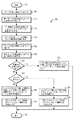
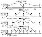
1つの実施形態は、図7に示されたフローチャート700と、図1に示されたサーボ制御システム100のブロック図を参照することによって良く理解することができる。ステップ705において、システムは、例えば、図2に示されたテープ移送システム200によって、テープヘッド(すなわちテープヘッド210)に沿って第1テープ速度V1で磁気テープ(すなわちテープ206)を動かす。第1テープ速度V1は、テープドライブの作動における基本テープ速度であり、ここでの第1テープ速度V1の説明に関しては、基本テープ速度は同一である。ステップ710において、サーボ信号プロセッサ192は、第1テープ速度V1に比例する第1サンプル周波数f1においてテープヘッドからテープヘッド位置信号を生成する。特定の実施形態においては、テープヘッド位置信号195は、テープ206上に書かれた時間基準サーボパターンを検出した結果として得られる。図8は、サーボ制御システム100の作動の間の種々のサンプル周波数及びテープ速度についての、テープヘッド位置信号195のサンプルタイミングを示す。テープが第1テープ速度V1で移動するときには、サンプル周期t1=1/f1の第1サンプル周波数f1810においてテープヘッド位置信号195を得ることができる。ステップ715において、第1テープ速度V1で作動するときに、システムは、第1サンプル周波数f1と同期する第1テープヘッド位置信号を処理する制御システム(すなわち制御システム100)を用いてテープヘッドの位置を制御する。制御システムは、第1クロスオーバー周波数fc1の最大位相応答を有する補償器(すなわち補償器185)を含む。ステップ718において、補償器(すなわち補償器185)は、第1クロスオーバー周波数fc1で作動して、微動アクチュエータ180を介してテープヘッドの制御を与え、システム作動仕様を達成する。第1クロスオーバー周波数fc1は、例えば、カーブ502(図5)が0dbラインと交差する場所(すなわちクロスオーバー周波数530)とすることができる。特定の実施形態においては、補償器185は、ディジタルフィルタ400の使用によるディジタルフィルタ係数D1、A1、A2・・・An、B1、B2・・・Bn及びゲイン係数G1の使用によって、適切な周波数ドメイン補償を与える。別の実施形態においては、補償器185は、ディジタルフィルタ300を使用してディジタルフィルタ係数C0、C 1 、C2、C3、・・・CN−2及びCN−1(すなわち要素310)を用いることにより適切な周波数ドメイン補償を与える。別の実施形態においては、補償器185は、アナログフィルタの使用により適切な周波数ドメイン補償を与える。特定の実施形態においては、ゲイン係数G1は、1に等しいものとすることができ、それにより必要とされない。特定の実施形態においては、ベース速度での作動のとき、補償器185は、第1サンプル周波数に同期した割り込み信号を処理システム(すなわち処理システム600)に与えて、補償器185のディジタルフィルタを実装するための計算を始めるサーボ信号プロセッサ192によって実装することができる。処理システムが割り込み信号を受け取るのに応答して、処理システムは、第1クロスオーバー周波数において最大位相応答を生成する出力値h(k)を与え、それによりサーボ制御システム100の安定した作動を与え、移動するテープに対するテープヘッドの横方向位置を制御する。この作動モードは、図8に示されたカーブ811を参照しながら良好に説明することができる。カーブ811は、第1テープ速度での作動のときV=V1であり、基本テープ速度である。実線の上向き矢印は、周期t1=1/f1における第1サンプル周波数f1と同期するテープヘッド位置信号を表す。サンプル周波数に同期したテープヘッド位置信号及び/又は割り込み信号は、例えば、テープヘッド位置信号が、割り込み信号193に対して特定の時間窓内で、及び/又は、例えばサンプル周波数信号の周期的波形の特徴の特定の位相で生じる場合に、同期すると考えられる。補償器を実装するための処理システム600の同期作動は、第1サンプル周波数f1と同期するテープヘッド位置信号を得ることができる時刻と、補償器の伝達関数を与えるのに用いられるディジタルフィルタ(すなわちディジタルフィルタ300又は400)からの実際の出力値h(k)との間に最小の位相遅延を与える。例えば、テープヘッド位置信号195及び割り込み信号193は、ヘッドテープインターフェース172におけるテープヘッドによるテープ上のサーボパターンの検出により、ほとんど瞬間的に、サーボ信号プロセッサ192によってもたらされる。割り込み信号193は、処理システム600に、計算(すなわちディジタルフィルタの実装)を行わせ、短い命令サイクル内で出力値h(k)を生成させ、結果として処理システム600は、テープヘッドによるサーボパターンの検出と同期した出力値を生成する。特定の実施形態においては、テープヘッド位置信号195と割り込み信号193は、それらの間に少しの時間遅延をもって一緒に生成され、時間遅延は、或る範囲又は「時間窓」をカバーすることができ、テープヘッド位置信号195及び割り込み信号193は、互いに事実上同時に発生すると考えることができる。
One embodiment can be better understood with reference to the
特定の実施形態においては、基本テープ速度での作動のとき、処理システムは、出力値h(k)を生成するためにディジタルフィルタ(すなわちディジタルフィルタ400)を用いることによって、第1クロスオーバー周波数における最大位相応答を生成する出力値h(k)を与え、ここで、
であり、Nはゼロより大きく、g(k)は上記の第2テープヘッド位置信号に比例し、g(k−1)はg(k)の前の値に等しく、D1、An、Bnは定数である。開ループ応答500(図5)によって示された代表的なサンプルについては、N=4が用いられ、補償器185の4次ディジタルフィルタ(すなわちディジタルフィルタ400)の実装をもたらす。第1サンプル周波数に同期した割り込み信号193を処理システム600の処理要素610に与えることは、全てのテープヘッド位置信号と同期する割り込み信号193を送信するように選択されるサーボ信号プロセッサ192によって達成することができる。処理システム600は、例えば、テープヘッド位置信号195が、一致すると考えられる割り込み信号193に対し特定の時間窓内で発生することを要求することによって、割り込み信号と一致するテープヘッド位置信号を処理するように設計し、又はプログラムすることができる。
In certain embodiments, when operating at the base tape speed, the processing system uses a digital filter (ie, digital filter 400) to generate an output value h (k), thereby at a first crossover frequency. Given an output value h (k) that produces a maximum phase response, where
N is greater than zero, g (k) is proportional to the second tape head position signal, g (k−1) is equal to the previous value of g (k), and D1, An, Bn are It is a constant. For the representative sample illustrated by the open loop response 500 (FIG. 5), N = 4 is used, resulting in an implementation of the fourth order digital filter of compensator 185 (ie, digital filter 400). Providing an interrupt
特定の実施形態においては、基本テープ速度での作動のとき、処理システムは、出力値h(k)を生成するためにディジタルフィルタ(すなわちディジタルフィルタ300)を用いることによって、第1クロスオーバー周波数における最大位相応答を生成する出力値h(k)を与え、ここで、
であり、Nはゼロより大きく、g(k)は上記の第2テープヘッド位置信号に比例し、g(k−n)はg(k)のn個前の値に等しく、ディジタルフィルタ係数Cnは定数である。開ループ応答500(図5)によって示された代表的なサンプルについては、N=17が用いられ、補償器185のための17次ディジタルフィルタ(すなわちディジタルフィルタ300)の実装をもたらす。第1サンプル周波数に同期した割り込み信号193を処理システム600の処理要素610に与えることは、全てのテープヘッド位置信号と同期する割り込み信号193を送信するように選択されるサーボ信号プロセッサ192によって達成することができる。処理システム600は、例えば、テープヘッド位置信号195が、一致すると考えられる割り込み信号193に対し特定の時間窓内で発生し、それにより処理システム600によって処理されることを要求することによって、割り込み信号と一致するテープヘッド位置信号を処理するように設計し、又はプログラムすることができる。
In certain embodiments, when operating at basic tape speed, the processing system uses a digital filter (ie, digital filter 300) to generate an output value h (k), thereby at a first crossover frequency. Given an output value h (k) that produces a maximum phase response, where
N is greater than zero, g (k) is proportional to the second tape head position signal, g (k−n) is equal to the nth previous value of g (k), and the digital filter coefficient Cn Is a constant. For the representative sample shown by the open loop response 500 (FIG. 5), N = 17 is used, resulting in the implementation of a 17th order digital filter (ie, digital filter 300) for the
ステップ720において、テープ移送システムは、磁気テープを、基本テープ速度の倍速である第2テープ速度で動かす。テープ速度は、例えば、テープ移送システム200によって第1テープ速度のM倍速である第2テープ速度に(すなわちV1からV2に、ここでV2=M*V1)変化させることができる。テープ速度の変化は、テープ206への異なるデータ読取/書き込み速度に適応させるために、又は他のシステム作動要求のために、テープ速度を増加させ又は減少させるようにテープ移送システム200に命令した結果としてもたらされる。この実施形態の作動は、或る値の範囲内でのテープ速度の変化について説明されるが、それぞれの周波数、速度などをより大きい値の範囲に適切にスケーリングすることによって、テープ速度のより大きい変化にも適応させることができるという利点がこの開示内容にあることが当業者には認識されるであろう。
In
ステップ725において、サーボ信号プロセッサ192は、テープヘッドから、第1サンプル周波数f1に倍数Mを掛けたものに比例する第2サンプル周波数f2の第2テープヘッド位置信号を生成する。例えば、2*V1に等しいテープ速度V2でテープ移送システム200を作動させる必要がある。M=2のとき、テープヘッド位置信号195は、第2サンプル周波数f2において得ることができ、ここでf2=2*f1である。
In
ステップ730において、倍数Mの値が、サーボ制御システム100の作動モードを決定する。1より大きい整数である倍数Mに応答して、制御がステップ735に移る。ステップ735において、サーボ制御システム100は、第1サンプル周波数f1と同期する第2テープヘッド位置信号を処理し、第1サンプル周波数f1と同期しない第2テープヘッド位置信号を廃棄して、テープヘッド210の位置を制御することによって作動する。この作動モードは、図8に示されたカーブ821を参照しながら良好に説明することができる。カーブ821は、第2テープ速度V2=2*V1における作動のとき、整数値2に等しいMをもたらす。実線の上向き矢印は、周期t1=1/f1における第1サンプル周波数f1と同期する第2テープヘッド位置信号を表す。サンプル周波数に同期したテープヘッド位置信号及び/又は割り込み信号は、例えば、テープヘッド位置信号が、割り込み信号193に対し特定の時間窓内で及び/又は例えばサンプル周波数信号の周期的波形の特徴の特定の位相で発生する場合には、同期すると考えられる。この開示で用いられる同期は、図8及び図9を参照しながら最も良く理解することができ、ここで、テープヘッド位置信号195の廃棄されたサンプル820は特定のサンプル周波数と同期せず、テープヘッド位置信号195のサーボサンプル(実線の上向き矢印で示され、「サーボサンプル」と付される)は特定のサンプル周波数と同期する。テープヘッド位置信号195の廃棄されたサンプル820は、破線の上向き矢印によって表され、これらのサンプルタイムにおいて得られる第2テープヘッド位置信号は、第1サンプル周波数f1と同期しないため廃棄される。M=2のときには、サーボ制御システム100(図1)による使用のためにサンプル周波数f1のテープヘッド位置信号が残され、その他の全てのテープヘッド位置信号が廃棄される。作動時に、テープヘッド位置信号195のサンプルは、例えば、命令、ソフトウェア、ハードワイヤコーディング、論理構成を有するプロセッサ610(例えば図6)、又は割り込み信号(例えば、サーボ信号プロセッサ192からの割り込み信号193)を受信したときに、割り込み信号193とテープヘッド位置信号195との間のタイミング関係、テープ速度及びテープヘッド位置信号195のサンプルの周波数に基づいてテープヘッド位置信号を廃棄する他の手段によって廃棄することができる。例えば、プロセッサ610は、受信した割り込み信号193の周波数に依存する命令を実行することができる。割り込み信号193の所与の周波数範囲においては、選択された数のテープヘッド位置信号195を廃棄する分岐命令を実行することができる。割り込み信号193の所与の周波数範囲が変化するのに伴って、選択された数のテープヘッド位置信号195を廃棄する分岐命令は、幅広い範囲をカバーするように変化する。M=2のとき、第2サンプル周波数f2=2*f1においてテープヘッド位置信号195が発生する。テープヘッド位置信号195の全ての他のサンプルを廃棄することによって、第1クロスオーバー周波数fc1(すなわちカーブ502及びカーブ512、図5)において補償器を作動させることができる。倍数Mのあらゆる整数値によって、ステップ730からステップ735への分岐による同様の作動がもたらされる。例えば、カーブ826(図8)は、第2テープ速度における作動のとき、V2=3*V1であり、整数値3に等しい倍数Mをもたらす。実線の上向き矢印は、周期t1=1/f1において第1サンプル周波数f1と同期する第2テープヘッド位置信号を表す。テープヘッド位置信号195の廃棄されたサンプル825は、破線の上向き矢印によって表され、これらのサンプルタイムにおいて得られる第2テープヘッド位置信号が第1サンプル周波数f1と同期しないので廃棄される。M=3のときには、3つのうち2つのテープヘッド位置信号が廃棄され、サーボ制御システム100による使用のためにサンプル周波数f1のテープヘッド位置信号が残される。作動時に、テープヘッド位置信号195のサンプルは、例えば、M=2のときの前述のプロセッサ610(図6)によって廃棄することができる。M=3のとき、テープヘッド位置信号195は、第2サンプル周波数f2=3*f1において発生する。テープヘッド位置信号195の全ての他のサンプルを廃棄することによって、補償器は、第1クロスオーバー周波数fc1(すなわちカーブ502及びカーブ512、図5)において作動することができる。整数値Mについての別の作動例は、整数値4に等しいMをもたらす第2テープ速度V2=4*V1における作動のとき、カーブ831(図8)によって示される。実線の上向き矢印は、周期t1=1/f1において第1サンプル周波数f1と同期する第2テープヘッド位置信号を表す。テープヘッド位置信号195の廃棄されたサンプル830は、破線の上向き矢印によって表され、第1サンプル周波数f1と同期しないこれらのサンプルタイムにおいて得られる第2テープヘッド位置信号のために廃棄される。M=4のとき、4つのうち3つのテープヘッド位置信号が廃棄され、サーボ制御システム100による使用のために、サンプル周波数f1におけるテープヘッド位置信号が残される。作動時に、テープヘッド位置信号195のサンプルは、例えば、M=2のときの前述のプロセッサ610(図6)によって廃棄することができる。M=4のとき、テープヘッド位置信号195は、第2サンプル周波数f2=4*f1において発生する。テープヘッド位置信号195の4つのサンプルのうち3つを廃棄することによって、補償器は、第1クロスオーバー周波数fc1(すなわちカーブ502及びカーブ512、図5)において作動することができる。
In
特定の実施形態においては、サーボ制御システム100は、第1サンプル周波数に同期した割り込み信号193を処理システム600に与えることによって、第1サンプル周波数f1と同期する第2テープヘッド位置信号を処理し、第1サンプル周波数f1と同期しない第2テープヘッド位置信号を廃棄する。処理システム600が割り込み信号193を受け取るのに応答して、処理システム600は、
からなる出力値h(k)を与え、ここで、
であり、Nはフィルタの次数で、N>1であり、g(k)は第2テープヘッド位置信号に比例し、g(k−1)はg(k)の前の値に等しく、D1、An、Bnは、ディジタルフィルタ係数の定数であり、G1はゲイン係数である。開ループ応答500(図5)によって示されたそれぞれのサンプルにおいては、N=4が用いられ、補償器185のための4次ディジタルフィルタ(すなわちディジタルフィルタ400)の実装がもたらされる。第1サンプル周波数に同期した割り込み信号193を処理システム600の処理要素610に与えることは、他の全てのテープヘッド位置信号(すなわちM=2のとき)と同期する割り込み信号193を送信することを選択するサーボ信号プロセッサ192によって達成することができ、それにより、サーボ制御システム100による使用のためにサンプル周波数f1のテープヘッド位置信号が残され、他の全てのテープヘッド位置信号が廃棄される(図8のカーブ821)。処理システム600は、例えば、テープヘッド位置信号195が、一致すると考えられる割り込み信号193に対する特定の時間窓内で発生し、それにより処理システム600によって処理されることを要求することによって、割り込み信号と一致するテープヘッド位置信号を処理するように設計し、又はプログラムすることができる。或いは、テープヘッド位置信号195のサンプルは、命令、ソフトウェア、ハードワイヤコーディング、論理構成、又はサーボ信号プロセッサ192における他の手段を有することによって、それらがプロセッサ610(図6)に送信される前に廃棄することができる。これは、限定する意味ではなくMの他の値のために用いることができる。kの各値は、処理システム600のために入力g(k)から出力h(k)が生成されるときのインターバルを表す。例えば、第1出力h(1)、(すなわちk=1)は、第1割り込み信号193及びテープヘッド位置信号195を受け取ったときに処理システム600によって生成される。次の出力値h(2)、(すなわちk=2)は、次の割り込み信号193及び次のテープヘッド位置信号195を受け取ったときに処理システム600によって生成され、以下同様である。全ての出力h(k)は、テープヘッドの位置を制御するための連続信号(ことによるとD/A変換器及びローパスフィルタを用いる後処理を有する)をともに生成する。
In certain embodiments, the
Given an output value h (k) consisting of:
N is the filter order , N> 1, g (k) is proportional to the second tape head position signal, g (k−1) is equal to the previous value of g (k), D1 , An, Bn are constants of the digital filter coefficient, and G1 is a gain coefficient. In each sample illustrated by the open loop response 500 (FIG. 5), N = 4 is used, resulting in the implementation of a fourth order digital filter (ie, digital filter 400) for
ステップ730において、倍数Mの値が整数でない場合には、ステップ740が実行される。倍数Mが整数ではなく、2より小さい場合には、ステップ745が実行される。ステップ745において、第2サンプル周波数f2、f2=M*f1と同期する第2テープヘッド位置信号を処理することによって、サーボ制御システム100がテープヘッドの位置を制御する。この作動モードは、図9に示されたカーブ911を参照することによって理解することができる。カーブ911は、第2テープ速度における作動のとき、V2=M*V1、M<2であり、整数ではない。1より小さい倍数Mの値においては、カーブ911は、t2=1/f2>1/f1と共に用いることができる。実線の上向き矢印は、t2=1/f2の周期、0<f2<2*f1である第2サンプル周波数f2と同期する第2のテープヘッド位置信号を表す。カーブ911においては、テープヘッド位置信号195のサンプルは廃棄されないので、サンプル周波数f2におけるテープヘッド位置信号は、サーボ制御システム100によって用いられる。作動時に、テープヘッド位置信号195のサンプルは、例えば、命令、ソフトウェア、ハードワイヤコーディング、論理構成を有するプロセッサ610(図6)、又は、割り込み信号193、テープヘッド位置信号195、テープ速度及びテープヘッド位置信号195のサンプルの周波数の間のタイミング関係に基づいてテープヘッド位置信号を受け取る割り込み信号(例えば、サーボ信号プロセッサ192からの割り込み信号193)を受信するときの他の手段によって選択される。ステップ745を実行した後にステップ748が実行される。ステップ748において、補償器185は、第1クロスオーバー周波数fc1に倍数Mがかけられたものにほぼ等しい周波数fpの最大位相応答を有し、かつ第1クロスオーバー周波数fc1にほぼ等しい第2クロスオーバー周波数fc2を有するように変更される。作動時には、第1クロスオーバー周波数fc1に等しい第2クロスオーバー周波数fc2を有し、結果としてサーボシステムの帯域幅に変化はないことが望ましいが、実際には、コンポーネント応答(すなわち、アクチュエータがテープヘッド210の位置を制御すること)における小さい変動が、結局fc2をfc1にほぼ等しいものにする。Mの増加に伴って、fpが比例的に増加し、サーボ制御システム100の作動の潜在的に大きい帯域幅がもたらされる。
を維持するために、ゲイン係数G1を変化させる必要がある。例えば、倍数M=1のとき(基本テープ速度のとき)、第1クロスオーバー周波数fc1における作動は、図5に示された開ループ大きさ応答カーブ501及び位相応答カーブ511によって表すことができる。Mを1より大きく増加させることにより、最大位相応答周波数fpにおける対応する増加を伴う大きさ応答カーブ503及び位相応答カーブ513がもたらされ、クロスオーバー周波数における変化はほとんどない
。Mを1より小さく減少させることにより、最大位相応答周波数fpにおける対応する減少を伴う大きさ応答カーブ502及び位相応答カーブ512がもたらされ、クロスオーバー周波数における変化はほとんどない
In order to maintain the above, it is necessary to change the gain coefficient G1. For example, when the multiple M = 1 (at the basic tape speed), the operation at the first crossover frequency fc1 can be represented by the open loop
. Decreasing M below 1 results in a
ステップ748において、補償器185は、第1クロスオーバー周波数fc1に倍数Mがかけられたものにほぼ等しい周波数の最大位相応答を有し、かつ第1クロスオーバー周波数fc1にほぼ等しい第2クロスオーバー周波数fc2を有するように補償器185を変更することによって第2クロスオーバー周波数fc2において作動する。これは、第2サンプル周波数f2と同期する割り込み信号を処理システム600に与えるサーボ信号プロセッサ192によって達成することができる。処理システム600が割り込み信号193を受け取るのに応答して、処理システム600は、
からなる出力値h(k)を与え、ここで、
であり、Nはフィルタの次数で、N>1であり、g(k)は第2テープヘッド位置信号に比例し、g(k−1)はg(k)の前の値に等しく、D1、An、Bnは、ディジタルフィルタ係数の定数であり、G2はゲイン係数であり、G2はゼロより大きく、倍数2*M 2 よりほぼ小さい(すなわち0<G2<2*M2 *G1)。
In
Given an output value h (k) consisting of:
N is the filter order , N> 1, g (k) is proportional to the second tape head position signal, g (k−1) is equal to the previous value of g (k), D1 , an, Bn is a constant of the digital filter coefficients, G2 is a gain factor, G2 is greater than zero, substantially less than a multiple 2 * M 2 (i.e. 0 <G2 <2 * M 2 * G1).
ここで説明されるサーボ制御システム100においては、第2クロスオーバー周波数fc2における補償器185の作動は迅速かつ効果的に達成される。第2サンプル周波数f2と同期する割り込み信号193を処理システム600に与え、このとき第1サンプル周波数f1に対する第2サンプル周波数f2のスケーリングが、第1クロスオーバー周波数fc1に倍数Mをかけたものにほぼ等しい最大位相応答の周波数のスケーリングに要求されるのと同じスケーリング(すなわち倍数M)であることにより、ディジタルフィルタ係数D1、An及びBnが定数であるとき、極及びゼロ、並びに結果として得られるディジタルフィルタ400の位相応答がサンプル周波数に対応するので、結果としてディジタルフィルタ係数D1、An及びBnに対する変化はない。ゲイン係数G2は、サーボ制御システム100が異なるサンプリング周波数f1、f2、f3などで動作する際に変化を要求する唯一の定数である。処理システム600によって実行される計算に関して変化される必要がある定数は1つのみであるので、システムの複雑さの減少と共に、メモリ要求が減少され、ソフトウェアが減少され、異なるテープ速度における作動の間の遷移時間が減少される。ゲイン係数G2は、Mと正確なシステム設計に依存する。例えば、第1クロスオーバー周波数fc1のときG1=1であり、第2クロスオーバー周波数のときG2である場合には、
特定の実施形態においては、倍数Mが1より小さい場合には、ゲイン係数G2は、第1クロスオーバー周波数fc1(すなわちM=1のとき)のために用いられるゲイン係数G1に倍数Mの2乗をかけたものの値にほぼ等しい
![]()
。開ループ応答500(図5)においては、N=4であり、二次周波数ドメインアクチュエータ伝達関数Act(s)(すなわち、Act(s)=1/s2であり、ここでs=σ+jω)が想定されるとき、G2は、クロスオーバー周波数及びサーボ制御システム100の作動の対応する帯域幅における変化のない状態を維持するために、Mが1より下に減少する際に
![]()
によってスケーリングされるべきである。特定の実施形態においては、アクチュエータ伝達関数Act(s)とアクチュエータ(すなわちアクチュエータ180)の伝達関数との間の相互作用は、Mが1より下に減少する際に、G1がMによって直線的にスケーリングされることを要求する。特定の実施形態においては、補償器185の伝達関数は、一次、三次などとすることができ、それによりMが減少するのに伴ってG1がそれぞれM、M3などによって直線的にスケーリングされることを要求する。
In a particular embodiment, when the multiple M is less than 1, the gain factor G2 is the square of the multiple M to the gain factor G1 used for the first crossover frequency fc1 (ie when M = 1). approximately equal to the value of the multiplied by the
![]()
. In the open loop response 500 (FIG. 5), N = 4 and a secondary frequency domain actuator transfer function Act (s) (ie, Act (s) = 1 / s2, where s = σ + jω) is assumed. When G2 is reduced, M2 decreases below 1 to maintain unchanged state in the crossover frequency and the corresponding bandwidth of
![]()
Should be scaled by. In certain embodiments, the interaction between the actuator transfer function Act (s) and the transfer function of the actuator (ie, actuator 180) is such that when M decreases below 1, G1 is linear by M. Require to be scaled. In certain embodiments, the transfer function of
特定の実施形態においては、倍数Mが1より大きい場合には、ゲイン係数G2は、第1クロスオーバー周波数fc1(すなわちM=1のとき)のために用いられるゲイン係数G1に倍数Mをかけたものの値にほぼ等しい。
![]()
開ループ応答500(図5)においては、N=4であり、二次周波数ドメインアクチュエータ伝達関数Act(s)(すなわち、Act(s)=1/s2であり、ここでs=σ+jω)が想定されるとき、G2は、クロスオーバー周波数及びサーボ制御システム100の作動の対応する帯域幅における変化のない状態を維持するために、Mが1より大きい値に増加する際に
によってスケーリングされるべきである。特定の実施形態においては、アクチュエータ伝達関数Act(s)と補償器185の伝達関数との間の相互作用は、Mが1より上に増加する際に、G2がMによってサブ直線的にスケーリングされることを要求する。特定の実施形態においては、アクチュエータ(すなわちアクチュエータ180)の伝達関数は、一次、三次などとすることができ、それによりMが増加するのに伴ってG2がそれぞれM、M3などによって直線的にスケーリングされることを要求する。ステップ748の実行の後に、制御がステップ795から終了に流れる。
In a particular embodiment, when the multiple M is greater than 1, the gain factor G2 has multiplied the gain factor G1 used for the first crossover frequency fc1 (ie when M = 1) by a multiple M. It is almost equal to the value of the thing.
![]()
In the open loop response 500 (FIG. 5), N = 4 and a secondary frequency domain actuator transfer function Act (s) (ie, Act (s) = 1 / s2, where s = σ + jω) is assumed. When G2 is increased, M is increased to a value greater than 1 in order to maintain the unchanged state in the crossover frequency and the corresponding bandwidth of
Should be scaled by. In certain embodiments, the interaction between the actuator transfer function Act (s) and the transfer function of
ステップ740において、倍数Mの値が整数ではなく、2より大きい場合には、ステップ760が実行される。ステップ760において、サーボ制御システム100は、第3サンプル周波数f3(ここでf3=K*f1であり、スケーリング・ナンバーK=M/(Mの整数値)である)と同期する第2テープヘッド位置信号を処理し、第3サンプル周波数f3と同期しない第2テープヘッド位置信号を廃棄することによって、テープヘッドの位置を制御する。この作動モードは、図9に示されたカーブ921及び931を参照することによって理解することができる。カーブ921は、第2テープ速度での作動のとき、V2=M*V1であり、ここで2<M<3である。この実線の上向き矢印は、周期t3=1/f3、
ステップ770において、補償器185は、第1クロスオーバー周波数fc1にスケーリング・ナンバーKがかけられたものにほぼ等しい周波数の最大位相応答を有し、かつ第1クロスオーバー周波数fc1にほぼ等しい第2クロスオーバー周波数fc2を有するように補償器185を変更することによって第2クロスオーバー周波数fc2において作動する。これは、第3サンプル周波数f3と同期する割り込み信号を処理システム600に与えるサーボ信号プロセッサ192によって達成することができる。処理システム600が割り込み信号193を受け取るのに応答して、処理システム600は、
からなる出力値h(k)を与え、ここで、
であり、Nはフィルタの次数で、N>1であり、g(k)は第2テープヘッド位置信号に比例し、g(k−1)はg(k)の前の値に等しく、D1、An、Bnは、ディジタルフィルタ係数であり、G3はゲイン係数であり、G3はゼロから2*K 2 までの適切な範囲(すなわち0<G3<2*K2 *G1)を有する。
In
Given an output value h (k) consisting of:
N is the filter order , N> 1, g (k) is proportional to the second tape head position signal, g (k−1) is equal to the previous value of g (k), D1 , an, Bn is a digital filter coefficients, G3 is a gain coefficient, G3 has an appropriate range of from zero to 2 * K 2 (i.e. 0 <G3 <2 * K 2 * G1).
ここで説明されるサーボ制御システム100においては、第2クロスオーバー周波数fc2における補償器185の作動は迅速かつ効果的に達成される。第3サンプル周波数f2と同期する割り込み信号193を処理システム600に与え、このとき第1サンプル周波数f1に対する第3サンプル周波数f3のスケーリングが、第1クロスオーバー周波数fc1にスケーリング・ナンバーKをかけたものにほぼ等しい最大位相応答の周波数のスケーリングに要求されるのと同じスケーリング(すなわちスケーリング・ナンバーK)であることにより、ディジタルフィルタ係数D1、An及びBnが定数であるとき、極及びゼロ、並びに結果として得られるディジタルフィルタ400の位相応答がサンプル周波数に対応するので、結果としてディジタルフィルタ係数D1、An及びBnに対する変化はない。ゲイン係数G3は、サーボ制御システム100が異なるサンプリング周波数f1、f2、f3などで動作する際に変化を要求する唯一の定数である。処理システム600によって実行される計算に関して変化される必要がある定数は1つのみであるので、システムの複雑さの減少と共に、メモリ要求が減少され、ソフトウェアが減少され、異なるテープ速度における作動の間の遷移時間が減少される。ゲイン係数G3は、Mと正確なシステム設計に依存する。例えば、第1クロスオーバー周波数fc1のときG1=1であり、第2クロスオーバー周波数のときG3である場合には、
は、ほぼ0<G3<2*M2の範囲となる。
In the
Is a range approximately 0 <G3 <of 2 * M 2.
特定の実施形態においては、第2クロスオーバー周波数fc2における作動のとき(10)、ゲイン係数G3は、第1クロスオーバー周波数fc1にスケーリング・ナンバーKをかけたもののために用いられるゲイン係数G1の値にほぼ等しい
。例えば、第1クロスオーバー周波数fc1のときG1=1(すなわちM=1)である場合には、第2クロスオーバー周波数fc2のときG3であり、fc2は0<G3<2*K2の範囲となる。開ループ応答500(図5)においては、N=4であり、二次周波数ドメインアクチュエータ伝達関数Act(s)(すなわち、Act(s)=1/s2であり、ここでs=σ+jω)が想定されるとき、G3は、クロスオーバー周波数及びサーボ制御システム100の作動の対応する帯域幅における変化のない状態を維持するために、Kが1より上に増加する際に、
によってスケーリングされるべきである。特定の実施形態においては、アクチュエータ伝達関数Act(s)と補償器185の伝達関数との間の相互作用は、Kが1より上に増加する際に、G1がKによってサブ直線的にスケーリングされることを要求する。特定の実施形態においては、アクチュエータ(すなわち微動アクチュエータ180)の伝達関数は、一次、三次などとすることができ、それによりKが増加するのに伴ってG1がそれぞれK、K3などによって直線的にスケーリングされることを要求する。
In a particular embodiment, when operating at the second crossover frequency fc2 (10), the gain factor G3 is the value of the gain factor G1 used for the first crossover frequency fc1 multiplied by the scaling number K. Almost equal to
. For example, in the case of G1 = 1 when the first crossover frequency fc1 (i.e. M = 1) is a G3 when the second crossover frequency fc2, fc2 is the range of 0 <G3 <2 * K 2 Become. In the open loop response 500 (FIG. 5), N = 4 and the secondary frequency domain actuator transfer function Act (s) (ie Act (s) = 1 / s 2 where s = σ + jω) As envisaged, G3 is the time when K increases above 1 to maintain the unchanged state in the crossover frequency and the corresponding bandwidth of operation of the
Should be scaled by. In a particular embodiment, the interaction between the actuator transfer function Act (s) and the transfer function of the
倍数Mが整数ではなく、3より大きい場合には、作動は、M>2のときの上述の作動と同じである。ここで説明された実施形態の作動をさらに説明するために、別の例がここで提示される。この例においては、サーボ制御システム100は、第3サンプル周波数f3(ここでf3=K*f1であり、スケーリング・ナンバーK=M/(Mの整数値)である)と同期する第2テープヘッド位置信号を処理し、第3サンプル周波数f3と同期しない第2テープヘッド位置信号を廃棄することによって、テープヘッドの位置を制御する。この作動モードは、図9に示されたカーブ931を参照することによって理解することができる。カーブ931は、第2テープ速度での作動のとき、V2=M*V1であり、ここで3<M<4である。この実線の上向き矢印は、周期t3=1/f3、
において第2サンプル周波数f3と同期する第2テープヘッド位置信号を表す。カーブ931については、テープヘッド位置信号195の廃棄されたサンプル930は、破線の上向き矢印によって表され、これらのサンプルタイムにおいて得られる第2テープヘッド位置信号は第3サンプル周波数f3と同期しないので廃棄される。3<M<4のとき、サーボ制御システム100による使用のために第3サンプル周波数f3のテープヘッド位置信号が残され、3つのテープヘッド位置信号のうち2つが廃棄される。作動時に、テープヘッド位置信号195のサンプルは、図8のカーブ821、826及び831を参照しながら上記で説明されたように廃棄することができる。補償器185は、第1クロスオーバー周波数fc1にスケーリング・ナンバーKがかけられたものにほぼ等しい周波数の最大位相応答を有し、かつ第1クロスオーバー周波数fc1にほぼ等しい第2クロスオーバー周波数fc2を有するように変更される。作動時には、第1クロスオーバー周波数fc1に等しい第2クロスオーバー周波数fc2を有し、結果としてサーボシステムの帯域幅に変化はないことが望ましいが、実際には、コンポーネント応答(すなわち、アクチュエータがテープヘッド210の位置を制御すること)における小さい変化が、結局fc2をfc1にほぼ等しいものにする。Kの増加に伴って、fpが比例的に増加し、サーボ制御システム100の作動の潜在的に大きい帯域幅がもたらされる。
を維持するために、ゲイン係数G1を変化させる必要がある。例えば、倍数M=1のとき、第1クロスオーバー周波数fc1における作動は、図5に示された開ループ大きさ応答カーブ501及び位相応答カーブ512によって表すことができる。M、それによりKを増加させることにより、最大位相応答周波数fpにおける対応する増加を伴う大きさ応答カーブ503及び位相応答カーブ513がもたらされ、クロスオーバー周波数における変化はほとんどない
。
If the multiple M is not an integer and is greater than 3, the operation is the same as described above when M> 2. To further illustrate the operation of the embodiments described herein, another example is presented here. In this example, the
2 represents a second tape head position signal synchronized with the second sample frequency f3. For
In order to maintain the above, it is necessary to change the gain coefficient G1. For example, when the multiple M = 1, the operation at the first crossover frequency fc1 can be represented by the open loop
.
補償器185は、第1クロスオーバー周波数fc1にスケーリング・ナンバーKがかけられたものにほぼ等しい周波数の最大位相応答を有し、かつ第1クロスオーバー周波数fc1にほぼ等しい第2クロスオーバー周波数fc2を有するように補償器185を変更することによって第2クロスオーバー周波数fc2において作動する。これは、第3サンプル周波数f3と同期する割り込み信号を処理システム600に与えるサーボ信号プロセッサ192によって達成することができる。処理システム600が割り込み信号193を受け取るのに応答して、処理システム600は、
からなる出力値h(k)を与え、ここで、
であり、Nはフィルタの次数で、N>1であり、g(k)は第2テープヘッド位置信号に比例し、g(k−1)はg(k)の前の値に等しく、D1、An、Bnは、ディジタルフィルタ係数であり、G3はゲイン係数であり、G3はゼロから2*K 2 までの適切な範囲(すなわち0<G3<2*K2 *G1)を有する。
The
Given an output value h (k) consisting of:
N is the filter order , N> 1, g (k) is proportional to the second tape head position signal, g (k−1) is equal to the previous value of g (k), D1 , an, Bn is a digital filter coefficients, G3 is a gain coefficient, G3 has an appropriate range of from zero to 2 * K 2 (i.e. 0 <G3 <2 * K 2 * G1).
ここで説明されるサーボ制御システム100においては、第2クロスオーバー周波数fc2における補償器185の作動は迅速かつ効果的に達成される。第3サンプル周波数f3と同期する割り込み信号193を処理システム600に与え、このとき第1サンプル周波数f1に対する第3サンプル周波数f3のスケーリングが、第1クロスオーバー周波数fc1にスケーリング・ナンバーKをかけたものにほぼ等しい最大位相応答の周波数のスケーリングに要求されるのと同じスケーリング(すなわちスケーリング・ナンバーK)であることにより、一定のディジタルフィルタ係数D1、An及びBnが定数であるとき、極及びゼロ、並びに結果として得られるディジタルフィルタ400の位相応答がサンプル周波数に対応するので、結果としてディジタルフィルタ係数D1、An及びBnに対する変化はない。ゲイン係数G3は、サーボ制御システム100が異なるサンプリング周波数f1、f2、f3などで動作する際に変化を要求する唯一の定数である。処理システム600によって実行される計算に関して変化される必要がある定数は1つのみであるので、システムの複雑さの減少と共に、メモリ要求が減少され、ソフトウェアが減少され、異なるテープ速度における作動の間の遷移時間が減少される。ゲイン係数G3は、Mと正確なシステム設計に依存する。例えば、第1クロスオーバー周波数fc1のときG1=1であり、第2クロスオーバー周波数のときG3である場合には、
![]()
![]()
特定の実施形態においては、第2クロスオーバー周波数、fc2における作動のとき、ゲイン係数G3は、第1クロスオーバー周波数fc1にスケーリング・ナンバーKをかけたもののために用いられるゲイン係数G1の値にほぼ等しい
。例えば、第1クロスオーバー周波数fc1のときG1=1である場合には、第2クロスオーバー周波数fc2のときG3であり、fc2は0<G3<2*K2の範囲となる。開ループ応答500(図5)においては、N=4であり、二次周波数ドメインアクチュエータ伝達関数Act(s)(すなわち、Act(s)=1/s2であり、ここでs=σ+jω)が想定されるとき、G3は、クロスオーバー周波数及びサーボ制御システム100の作動の対応する帯域幅における変化のない状態を維持するために、Kが1より上に増加する際に、
によってスケーリングされるべきである。特定の実施形態においては、アクチュエータ伝達関数Act(s)と補償器185の伝達関数との間の相互作用は、Kが1より上に増加する際に、G1がKによってサブ直線的にスケーリングされることを要求する。特定の実施形態においては、アクチュエータ(すなわち微動アクチュエータ180)の伝達関数は、一次、三次などとすることができ、それによりKが増加するのに伴ってG1がそれぞれK、K3などによって直線的にスケーリングされることを要求する。
In a particular embodiment, when operating at the second crossover frequency, fc2, the gain factor G3 is approximately the value of the gain factor G1 used for the first crossover frequency fc1 multiplied by the scaling number K. equal
. For example, if the first is G1 = 1 when crossover frequency fc1 is a G3 when the second crossover frequency fc2, fc2 is in the range of 0 <G3 <2 * K 2 . In the open loop response 500 (FIG. 5), N = 4 and the secondary frequency domain actuator transfer function Act (s) (ie Act (s) = 1 / s 2 where s = σ + jω) As envisaged, G3 is the time when K increases above 1 to maintain the unchanged state in the crossover frequency and the corresponding bandwidth of operation of the
Should be scaled by. In a particular embodiment, the interaction between the actuator transfer function Act (s) and the transfer function of the
上記で説明された実施形態の動作は、図10を参照すると良く理解することができ、異なるテープ速度のときのサンプル周波数1010及びサンプル周期1020の正規化された値1000がグラフ形式で示されている。カーブ1010は、正規化されたサンプル周波数であり、カーブ1020は、正規化されたサンプル周期である。正規化されたテープ速度1のとき、正規化されたサンプル周波数1010及び正規化されたサンプル周期1020は、各々1に等しい。Mが整数でない値であり、1<M<2であるとき、正規化されたテープ速度Vは、1<V<2の範囲を有し、正規化されたサンプル周波数1010fは、1<f<2の範囲を有し、正規化されたサンプル周期t=1/fである。Mが整数値であり、M=1,2,3...であるとき、正規化されたテープ速度Vも整数であり、V=1,2,3...と共に変化する。正規化されたテープ速度Vの各整数値において、正規化されたサンプル周波数1010fは値1を有し、正規化されたテープ速度Vの各整数値において、カーブ821、826及び831(図8)を参照しながら上記で説明されたようにテープヘッド位置信号が廃棄されるので、正規化されたサンプル周期t=1/fも1に等しい。また、正規化されたクロスオーバー周波数fcは、正規化されたテープ速度Vの各整数値について値1を有する。
The operation of the embodiment described above can be better understood with reference to FIG. 10, where the normalized
正規化されたサンプル周波数1010が、正規化されたテープ速度V=1における正規化されたサンプル周波数1010にスケーリング・ナンバーK(K=M/(INT(M))であり、「INT」は、Mの端数を切り捨てて最も近い整数値にすることによってMの整数値をとる)をかけることによって決まるので、正規化されたサンプル周波数1010及び正規化されたサンプル周期1020は、Mが2を上回る非整数値まで増加するのに伴って、それぞれ図10に示されるように減少される。Mが1より低い非整数値まで減少するのに伴って、正規化されたサンプル周波数1010は、Mと共に直線的に減少し、正規化されたサンプル周期1020は、図10に示されるように増加する。図示する目的のために、図10は、正規化されたテープ速度Vを示し、ここで
特定の実施形態においては、テープヘッド位置信号の製造は、時間基準サーボシステムを用いて達成される。ここで説明された実施形態と共に用いられる時間基準サーボ信号を用いるトラック追従サーボシステムの1つの実装の説明は、特許文献2に開示されている。 In certain embodiments, the production of the tape head position signal is accomplished using a time reference servo system. A description of one implementation of a track following servo system using a time-based servo signal used with the embodiments described herein is disclosed in US Pat.
特定の実施形態においては、1つ又はそれ以上の出願人の実施形態は、テープ(すなわちテープ206)に対するデータの読み取り及び書き込みのためのテープドライブを含む。例えば、限定する意味ではなく、ここで説明されるサーボ制御システム100及びその作動は、例えば、磁気テープに対するデータの有効な書き込み及び読み取りのためにテープヘッド位置制御を与えるべく、例えば図11に示されるような読み取り/書き込みテープドライブといった読み取り/書き込みテープドライブに用いられる。本発明と同一の譲受人に譲渡された特許文献3は、こうした読み取り/書き込みテープドライブを説明するものである。
In certain embodiments, one or more Applicants' embodiments include a tape drive for reading and writing data to a tape (ie, tape 206). For example, and not by way of limitation, the
特定の実施形態においては、1つ又はそれ以上の出願人の実施形態は、データ・ストレージ・メディアにアクセスするための自動化されたデータ・ストレージ・ライブラリを含む。自動化されたデータ・ストレージ・ライブラリは、例えば、データ・ストレージ・メディアにアクセスし、移動するためのアクセサーと、データ・ストレージ・メディアのストレージのためのストレージ・シェルフとを含む。例えば、ここで説明されるサーボ制御システム100とその作動は、限定する意味ではなく、データ・ストレージ・メディアに関連する磁気テープに対するデータの有効な書き込み及び読み取りのためにテープヘッド位置制御を与えるべく、例えば図12に示される自動化データ・ストレージ・ライブラリにおいて読み取り/書き込みテープドライブに用いられる。本発明と同一の譲受人に譲渡された特許文献4は、こうした自動化されたメディア・ライブラリを説明するものである。
In certain embodiments, one or more Applicants' embodiments include an automated data storage library for accessing data storage media. An automated data storage library includes, for example, an accessor for accessing and moving data storage media and a storage shelf for storage of data storage media. For example, the
実施形態は、時間基準サーボ信号に関連して説明されたが、本発明は時間基準サーボ信号に限定されることを意図されるものではないことが当業者には認識されるであろう。むしろ、本発明は、あらゆるサーボ信号と共に用いることができる。 Although the embodiments have been described with reference to a time reference servo signal, those skilled in the art will recognize that the invention is not intended to be limited to a time reference servo signal. Rather, the present invention can be used with any servo signal.
ここで開示された本発明は、ソフトウェア、ファームウェア、ハードウェア又はこれらのいずれかの組み合わせを製造するための標準的プログラミング及び/又は工学技術を用いる方法、装置又は製品として実装することができる。ここで用いられる「製品」という用語は、ハードウェア論理(例えば、集積回路チップ、プログラマブルゲートアレイ(PGA)において実装されるコード又は論理、特定用途向け集積回路(ASIC)など)、又はコンピュータ可読媒体(例えば、磁気ストレージ媒体(例えば、ハードディスクドライブ、ディスケット、テープなど)、光学的ストレージ(CD−ROM、光ディスクなど)、揮発性及び不揮発性メモリデバイス(例えば、EEPROM、ROM、PROM、RAM、DRAM、SRAM、ファームウェア、プログラマブル論理など)のことをいう。コンピュータ可読媒体におけるコードは、プロセッサによってアクセスされ、実行される。コードはさらに、伝達媒体を通じて又はネットワーク上のファイルサーバからアクセス可能である。こうした場合には、コードが実装される製品は、ネットワーク伝送ライン、無線伝送媒体、スペースを通って伝搬する信号、無線波、赤外線信号などといった伝送媒体を含むことができる。もちろん、本発明の範囲から逸脱することなく、この構成に多くの変更を行うことができ、製品は、当該技術分野では公知のあらゆる情報搬送媒体を含むことができることを当業者であれば理解するであろう。 The invention disclosed herein can be implemented as a method, apparatus or product using standard programming and / or engineering techniques to produce software, firmware, hardware or any combination thereof. The term “product” as used herein refers to hardware logic (eg, integrated circuit chip, code or logic implemented in a programmable gate array (PGA), application specific integrated circuit (ASIC), etc.), or computer readable medium. (Eg, magnetic storage media (eg, hard disk drives, diskettes, tapes, etc.), optical storage (CD-ROM, optical discs, etc.), volatile and non-volatile memory devices (eg, EEPROM, ROM, PROM, RAM, DRAM, (SRAM, firmware, programmable logic, etc.) The code on a computer readable medium is accessed and executed by a processor, which is further accessed through a transmission medium or from a file server on a network. In such cases, the product in which the code is implemented may include transmission media such as network transmission lines, wireless transmission media, signals propagating through space, radio waves, infrared signals, and the like. Those skilled in the art will appreciate that many modifications can be made to this configuration without departing from the scope of the present invention, and that the product can include any information carrier medium known in the art. I will.
特定の実施形態においては、本発明は、図7に示されたフローチャートに記載されたステップを実行するために、プロセッサ610(図6)及び/又は処理要素190(図1)によって実行される命令を含む。 In certain embodiments, the present invention provides instructions executed by processor 610 (FIG. 6) and / or processing element 190 (FIG. 1) to perform the steps described in the flowchart shown in FIG. including.
他の実施形態においては、本発明は、サーボ制御システム100の外部の又は内部のコンピュータによって実行される、他のいずれかのコンピュータ・プログラム製品に存在する命令を含む。いずれの場合にも、命令は、例えば、磁気情報ストレージ媒体、光学的情報ストレージ媒体、電気的情報ストレージ媒体などを含む情報ストレージ媒体にエンコードすることができる。ここで意味する「電気的ストレージ媒体」とは、例えば、PROM、EPROM、EEPROM、フラッシュPROM、コンパクトフラッシュ、スマートメディアなどといったデバイスを意味する。
In other embodiments, the present invention includes instructions residing in any other computer program product that are executed by a computer external or internal to
特定の実施形態は、コンピュータ可読コードをシステムに組み込んで、説明された実施形態の作動を実行することを含む、人による又は自動化された処理システムによる計算インフラを利用するための方法に向けられたものである。例えば、図7は、説明された実施形態の使用によってテープヘッドの位置を制御するためのステップを示す。システムと組み合わされたコード(すなわち、サーボ制御システム100)は、ここで説明された実施形態の作動のためのステップを実行することができる。計算インフラの利用は、サービス、製造及び/又はここで説明された実施形態の構成の間に実行することができる。例えば、コンサルティング・ビジネスは、多くのシステムのサービス責任を有することがある。こうしたサービス責任は、システムの更新、エラー診断、パフォーマンスの調整、及び強化、新しいハードウェアのインストール、新しいソフトウェアのインストール、他のシステムとの構成などのようなタスクを含む。このサービスの一部として、別のサービスとして、サービスマンは、ここで説明された実施形態の動作を効果的にイネーブルにするように、ここで説明された技術に従ってシステムを構成することができる。例えば、こうした構成は、コンピュータメモリに、命令、パラメータ、定数(すなわち、ディジタルフィルタ係数定数An、Bnなど)、割り込みベクトルをローディングして、コードが実行されたときに、システムがここで説明された実施形態を実装するために説明された技術を実行できるようにすることを含む。 Certain embodiments are directed to a method for utilizing a computing infrastructure by a human or automated processing system that includes incorporating computer readable code into the system to perform the operations of the described embodiments. Is. For example, FIG. 7 shows the steps for controlling the position of the tape head by use of the described embodiment. A code combined with the system (ie, servo control system 100) can perform the steps for operation of the embodiments described herein. Utilization of the computing infrastructure can be performed during service, manufacturing and / or configuration of the embodiments described herein. For example, a consulting business may have service responsibilities for many systems. These service responsibilities include tasks such as system updates, error diagnosis, performance tuning and enhancement, new hardware installation, new software installation, configuration with other systems, and the like. As part of this service, as a separate service, a service person can configure the system according to the techniques described herein to effectively enable the operation of the embodiments described herein. For example, such a configuration is described here when the computer is loaded with instructions, parameters, constants (ie, digital filter coefficient constants An, Bn, etc.), interrupt vectors, and the code is executed. Including enabling the techniques described to implement the embodiments to be performed.
上記の説明には、説明の目的上、本発明の十分な理解を与えるために特定の用語を用いた。しかしながら、当業者であれば、本発明を実施するために特定の詳細は要求されないことを理解するであろう。他の場合には、本発明からの不必要な混乱を避けるために、周知の回路及びデバイスがブロック図の形態で示される。したがって、本発明の特定の実施形態の上記の説明は、図示及び説明のために与えられる。それらは、網羅的なものとなること、又は本発明を開示された正確な形態に限定することを意図されるものではない。明らかに、上記の技術に照らして多くの変更及び変化が可能である。 In the above description, for purposes of explanation, specific terminology has been used in order to provide a thorough understanding of the present invention. However, one of ordinary skill in the art appreciates that specific details are not required in order to practice the invention. In other instances, well-known circuits and devices are shown in block diagram form in order to avoid unnecessary confusion from the present invention. Accordingly, the foregoing description of specific embodiments of the invention is provided for purposes of illustration and description. They are not intended to be exhaustive or to limit the invention to the precise form disclosed. Obviously, many modifications and variations are possible in light of the above techniques.
図7の論理は、特定の順番で起こる特定の動作を説明している。代替的実装においては、特定の論理動作は、異なる順序で実行され、変更され又は除去される。また、上述の論理にステップを付加し、さらに説明された実装に適合させることができる。さらに、ここで説明された動作は、順番に行われることができ、又は特定の動作は、平行して処理されることができ、或いは単一プロセスによって実行される説明された動作は、分散プロセスによって実行することができる。 The logic of FIG. 7 describes specific operations that occur in a specific order. In alternative implementations, certain logic operations are performed, changed or removed in a different order. Also, steps can be added to the above logic to further adapt the described implementation. Further, the operations described herein can be performed in sequence, or specific operations can be processed in parallel, or the described operations performed by a single process can be performed in a distributed process. Can be executed by.
図7の論理は、ソフトウェアに実装されるものとして説明された。この論理は、ホストシステムのオペレーティング・システムの一部として、又はアプリケーション・プログラムとすることができる。さらに別の実装においては、この論理は、サーボ制御システム100によって管理されたストレージエリアに、又は読み取り専用メモリに、或いは他のハードワイヤ型デバイスに維持することができる。好ましい論理は、ハードディスクドライブに又はプログラマブル及び非プログラマブル・ゲート・アレイ論理に実装することができる。
The logic of FIG. 7 has been described as being implemented in software. This logic can be part of the host system operating system or an application program. In yet another implementation, this logic may be maintained in a storage area managed by
実施形態は、本発明及びその実用化の原理を最も良く説明し、それにより、当業者が本発明及び検討された特定の使用に適した種々の変更を伴う種々の実施形態を最も良く用いることを可能にするために選択され、記載される。本発明の範囲は、特許請求の範囲の請求項及びその均等物によって定められることを意図されている。 The embodiments best explain the principles of the invention and its practical application so that those skilled in the art will best use the various embodiments with various modifications suitable for the invention and the particular use discussed. Selected and described to enable It is intended that the scope of the invention be defined by the claims appended hereto and their equivalents.
100:サーボ制御システム
150:サーボ信号
171:サーボセンサ及び前置増幅器
172:ヘッドテープインターフェース
173:ディジタルサンプラ
174:ディジタルフィルタ
Filtered servo signal フィルタリングされたサーボ信号
175 ピーク検出器
176 時間基準変換器
180 微動アクチュエータ
182 粗動アクチュエータ
185 補償器
186 読み取り/ラグ
187 積分器/イコライザ
190 処理要素
191 テープ速度
192 サーボ信号プロセッサ
193 割り込み信号
195 テープヘッド位置信号
100: Servo control system 150: Servo signal 171: Servo sensor and preamplifier 172: Head tape interface 173: Digital sampler 174: Digital filter Filtered servo signal Filtered
Claims (20)
前記方法が、 前記第1サンプル周波数に同期した前記第1テープヘッド位置信号を処理するものであって、第1クロスオーバー周波数における最大位相応答を有する補償器を含む制御システム、を用いて前記テープヘッドの位置を制御するステップと、
前記第1サンプル周波数に同期した割り込み信号を処理システムに与えるステップと、
前記処理システムが前記割り込み信号を受け取るのに応答して、前記処理システムが、前記第1クロスオーバー周波数で前記最大位相応答を生成する出力値h(k)を与えるステップと含む
方法。 A method of operating a tape drive having a basic tape speed for moving a magnetic tape along a tape head and generating a first tape head position signal from the tape head at a first sample frequency proportional to the basic tape speed. Because
The method uses the control system to process the first tape head position signal synchronized to the first sample frequency and includes a compensator having a maximum phase response at a first crossover frequency. Controlling the position of the head;
Providing an interrupt signal synchronized to the first sample frequency to a processing system;
Responsive to the processing system receiving the interrupt signal, the processing system providing an output value h (k) that produces the maximum phase response at the first crossover frequency.
請求項1に記載の方法。 The processing system providing an output value h (k) further includes generating the output value h (k) using a digital filter, the output value h (k) being given by:
The method of claim 1.
前記テープヘッドの位置を制御するように構成される制御システムを含むシステムであり、
前記制御システムは、前記基本テープ速度に比例する第1サンプル周波数で前記テープヘッドから第1テープヘッド位置信号を生成し、前記第1テープヘッド位置信号と、前記第1サンプル周波数に同期した割り込み信号とを処理システムに与えるように構成されるサーボ信号プロセッサを含み、
前記処理システムは、前記割り込み信号を受け取るのに応答して、第1クロスオーバー周波数の最大位相応答を生成する出力値h(k)を与えるように構成される、
システム。 A tape transport system configured to move the tape along the tape head at a basic tape speed;
A system including a control system configured to control the position of the tape head;
The control system generates a first tape head position signal from the tape head at a first sample frequency proportional to the basic tape speed, and the first tape head position signal and an interrupt signal synchronized with the first sample frequency. A servo signal processor configured to provide a processing system with
The processing system is configured to provide an output value h (k) that produces a maximum phase response of a first crossover frequency in response to receiving the interrupt signal.
system.
前記テープに対してデータを読み取り、書き込むための読み取り/書き込みヘッドと、
前記読み取り/書き込みヘッドの位置を設定するために前記読み取り/書き込みヘッドに結合されたアクチュエータと、
をさらに含む、請求項6に記載のシステム。 The system includes a tape drive;
A read / write head for reading and writing data to the tape;
An actuator coupled to the read / write head to set the position of the read / write head;
The system of claim 6, further comprising:
前記データ・ストレージ・メディアにアクセスし、移動させるためのアクセサーと、
前記データ・ストレージ・メディアのストレージのためのストレージ・シェルフと、
をさらに含む、請求項6に記載のシステム。 The system includes an automated data storage library for accessing data storage media;
An accessor for accessing and moving the data storage medium;
A storage shelf for storage of said data storage media;
The system of claim 6, further comprising:
基本テープ速度に比例する第1サンプル周波数でテープヘッドから第1テープヘッド位置信号を生成し、前記第1テープヘッド位置信号と、前記第1サンプル周波数に同期した割り込み信号を処理システムに与えるように構成されるサーボ信号プロセッサを含み、
前記処理システムは、前記処理システムが前記割り込み信号を受け取るのに応答して、前記処理システムが第1クロスオーバー周波数の最大位相応答を生成する出力値h(k)を与えるように構成される、制御システム。 A control system configured to control the position of the tape head,
A first tape head position signal is generated from the tape head at a first sample frequency proportional to the basic tape speed, and the first tape head position signal and an interrupt signal synchronized with the first sample frequency are provided to the processing system. A servo signal processor configured,
The processing system is configured to provide an output value h (k) that produces a maximum phase response of a first crossover frequency in response to the processing system receiving the interrupt signal. Control system.
前記方法が、
前記第1サンプル周波数に同期した前記第1テープヘッド位置信号を処理するための、第1クロスオーバー周波数における最大位相応答を有する補償器を含む制御システムを用いて前記テープヘッドの位置を制御するステップと、
前記第1サンプル周波数に同期した割り込み信号を処理システムに与えるステップと、
前記処理システムが前記割り込み信号を受け取るのに応答して、前記処理システムが前記第1クロスオーバー周波数で前記最大位相応答を生成する出力値h(k)を与えるようにするステップと、
を含む、コンピュータ・プログラム。 The digital processor has a basic tape speed for moving the magnetic tape along the tape head and generates a first tape head position signal from the tape head at a first sample frequency proportional to the basic tape speed. A computer program that executes the method steps of operating a tape drive,
Said method comprises
Controlling the position of the tape head using a control system including a compensator having a maximum phase response at a first crossover frequency for processing the first tape head position signal synchronized to the first sample frequency. When,
Providing an interrupt signal synchronized to the first sample frequency to a processing system;
In response to the processing system receiving the interrupt signal, the processing system providing an output value h (k) that produces the maximum phase response at the first crossover frequency;
Including computer programs.
Applications Claiming Priority (1)
| Application Number | Priority Date | Filing Date | Title |
|---|---|---|---|
| US11/012,950 US7110212B2 (en) | 2004-12-15 | 2004-12-15 | Compensator for a synchronous sampling time-base servo system |
Publications (3)
| Publication Number | Publication Date |
|---|---|
| JP2006172704A JP2006172704A (en) | 2006-06-29 |
| JP2006172704A5 JP2006172704A5 (en) | 2009-07-02 |
| JP4448491B2 true JP4448491B2 (en) | 2010-04-07 |
Family
ID=36583495
Family Applications (1)
| Application Number | Title | Priority Date | Filing Date |
|---|---|---|---|
| JP2005360532A Expired - Fee Related JP4448491B2 (en) | 2004-12-15 | 2005-12-14 | Compensator for synchronous sampling time-based servo system |
Country Status (3)
| Country | Link |
|---|---|
| US (1) | US7110212B2 (en) |
| JP (1) | JP4448491B2 (en) |
| CN (1) | CN100377073C (en) |
Families Citing this family (8)
| Publication number | Priority date | Publication date | Assignee | Title |
|---|---|---|---|---|
| US8014879B2 (en) * | 2005-11-11 | 2011-09-06 | L&L Engineering, Llc | Methods and systems for adaptive control |
| US7280307B2 (en) * | 2006-02-10 | 2007-10-09 | International Business Machines Corporation | Track following servo actuator offset calibration for tape drive |
| US8050800B2 (en) * | 2007-10-21 | 2011-11-01 | Ge Intelligent Platforms, Inc. | Method and system for meeting end conditions in a motion control system |
| US7847496B2 (en) * | 2008-02-15 | 2010-12-07 | International Business Machines Corporation | Dynamic tape drive calibration |
| US8665552B2 (en) | 2010-07-12 | 2014-03-04 | Hewlett-Packard Development Company, L.P. | Controlling positions of storage media heads |
| US8773800B2 (en) * | 2010-10-08 | 2014-07-08 | Quantum Corporation | Adaptive disturbance compensation with multi-rate synchronized sampling |
| US9159347B1 (en) * | 2014-06-17 | 2015-10-13 | International Business Machines Corporation | Usage of state information from state-space based track-follow controller |
| US9524741B1 (en) * | 2015-10-30 | 2016-12-20 | International Business Machines Corporation | High-density pattern detector for hybrid servo patterns |
Family Cites Families (8)
| Publication number | Priority date | Publication date | Assignee | Title |
|---|---|---|---|---|
| US4794472A (en) * | 1985-07-30 | 1988-12-27 | Matsushita Electric Industrial Co., Ltd. | Video tape reproducing apparatus with a processor that time-shares different operations |
| US5055951A (en) * | 1989-03-10 | 1991-10-08 | Irwin Magnetic Systems, Inc. | Method and apparatus for servo-positioning movable transducer heads |
| US5689384A (en) * | 1994-06-30 | 1997-11-18 | International Business Machines Corporation | Timing based servo system for magnetic tape systems |
| US6201652B1 (en) * | 1998-05-29 | 2001-03-13 | Stmicroelectronics, Inc. | Method and apparatus for reading and writing gray code servo data to magnetic medium using synchronous detection |
| US6574066B1 (en) * | 2000-02-17 | 2003-06-03 | Imation Corp. | Time-based optical servo system and method |
| US6356803B1 (en) * | 2000-05-19 | 2002-03-12 | International Business Machines Corporation | Automated data storage library distributed control system |
| US6587303B1 (en) * | 2000-06-09 | 2003-07-01 | International Business Machines Corporation | Servo control of a coarse actuator |
| US6813112B2 (en) * | 2001-09-06 | 2004-11-02 | International Business Machines Corporation | Method, apparatus and software for tape drive mechanical fault detection |
-
2004
- 2004-12-15 US US11/012,950 patent/US7110212B2/en not_active Expired - Fee Related
-
2005
- 2005-11-17 CN CNB2005101254311A patent/CN100377073C/en not_active Expired - Fee Related
- 2005-12-14 JP JP2005360532A patent/JP4448491B2/en not_active Expired - Fee Related
Also Published As
| Publication number | Publication date |
|---|---|
| CN100377073C (en) | 2008-03-26 |
| US7110212B2 (en) | 2006-09-19 |
| CN1801333A (en) | 2006-07-12 |
| US20060126214A1 (en) | 2006-06-15 |
| JP2006172704A (en) | 2006-06-29 |
Similar Documents
| Publication | Publication Date | Title |
|---|---|---|
| US7362537B2 (en) | Velocity adaptive compensator for a synchronous sampling time-base servo system | |
| JP4448491B2 (en) | Compensator for synchronous sampling time-based servo system | |
| US10199062B2 (en) | Balanced delay and resolution for high density servo systems | |
| JP2714905B2 (en) | Positioning control device | |
| US8094407B2 (en) | Servomechanism with adjustable predictor filter | |
| JP7116378B2 (en) | Tape transport control system and method with time-varying tension disturbance suppression | |
| KR100699854B1 (en) | Method for suppressing resonance using an notch filter and appartus thereof | |
| US6831809B2 (en) | Rotary recording apparatus and method of controlling the apparatus | |
| WO1999008268A1 (en) | Method of implementing a linear discrete-time state-space servo control system on a fixed-point digital signal processor in a disc drive | |
| US8780481B2 (en) | Fast recovery to a write state | |
| US6940683B2 (en) | Matched filter detection for time based servo signals in a tape drive | |
| KR100408409B1 (en) | Apparatus and method for eliminating resonance frequency of system | |
| US7999500B1 (en) | Calibrating spindle motor controllers | |
| JP2001282347A (en) | Feedback controller and feedback control method and magnetic disk device and method for controlling the same | |
| US9208815B1 (en) | Data storage device dynamically reducing coast velocity during seek to reduce power consumption | |
| US6153998A (en) | Method of controlling a two-degree-of-freedom control system | |
| US10141016B2 (en) | Balanced delay and resolution for timing based servo systems | |
| US6771455B1 (en) | Control system and control method for positioning a head above a desired position on disk | |
| JP2009104710A (en) | Magnetic disk device and control method of magnetic head | |
| US20050259348A1 (en) | Method and apparatus for reducing vibration in a dynamic system | |
| JP2006139905A (en) | System and method for tape drive control | |
| US9418689B2 (en) | Data storage device generating an operating seek time profile as a function of a base seek time profile | |
| JP2006139906A (en) | System and method for tape drive control | |
| US8615539B2 (en) | Coefficient control for filter in magnetic media read channel | |
| JP2008010141A (en) | Hard disk drive track following control method and apparatus |
Legal Events
| Date | Code | Title | Description |
|---|---|---|---|
| A621 | Written request for application examination |
Free format text: JAPANESE INTERMEDIATE CODE: A621 Effective date: 20080924 |
|
| A521 | Request for written amendment filed |
Free format text: JAPANESE INTERMEDIATE CODE: A523 Effective date: 20090206 |
|
| A521 | Request for written amendment filed |
Free format text: JAPANESE INTERMEDIATE CODE: A523 Effective date: 20090518 |
|
| A871 | Explanation of circumstances concerning accelerated examination |
Free format text: JAPANESE INTERMEDIATE CODE: A871 Effective date: 20090518 |
|
| A975 | Report on accelerated examination |
Free format text: JAPANESE INTERMEDIATE CODE: A971005 Effective date: 20090615 |
|
| A131 | Notification of reasons for refusal |
Free format text: JAPANESE INTERMEDIATE CODE: A131 Effective date: 20090623 |
|
| A521 | Request for written amendment filed |
Free format text: JAPANESE INTERMEDIATE CODE: A523 Effective date: 20090924 |
|
| TRDD | Decision of grant or rejection written | ||
| A01 | Written decision to grant a patent or to grant a registration (utility model) |
Free format text: JAPANESE INTERMEDIATE CODE: A01 Effective date: 20100112 |
|
| A01 | Written decision to grant a patent or to grant a registration (utility model) |
Free format text: JAPANESE INTERMEDIATE CODE: A01 |
|
| A61 | First payment of annual fees (during grant procedure) |
Free format text: JAPANESE INTERMEDIATE CODE: A61 Effective date: 20100122 |
|
| FPAY | Renewal fee payment (event date is renewal date of database) |
Free format text: PAYMENT UNTIL: 20130129 Year of fee payment: 3 |
|
| R150 | Certificate of patent or registration of utility model |
Free format text: JAPANESE INTERMEDIATE CODE: R150 |
|
| FPAY | Renewal fee payment (event date is renewal date of database) |
Free format text: PAYMENT UNTIL: 20140129 Year of fee payment: 4 |
|
| LAPS | Cancellation because of no payment of annual fees |