JP4448460B2 - Inner mold of mold for molding cylindrical concrete products - Google Patents
Inner mold of mold for molding cylindrical concrete products Download PDFInfo
- Publication number
- JP4448460B2 JP4448460B2 JP2005039067A JP2005039067A JP4448460B2 JP 4448460 B2 JP4448460 B2 JP 4448460B2 JP 2005039067 A JP2005039067 A JP 2005039067A JP 2005039067 A JP2005039067 A JP 2005039067A JP 4448460 B2 JP4448460 B2 JP 4448460B2
- Authority
- JP
- Japan
- Prior art keywords
- peripheral wall
- top plate
- inner mold
- wall dividing
- mold
- Prior art date
- Legal status (The legal status is an assumption and is not a legal conclusion. Google has not performed a legal analysis and makes no representation as to the accuracy of the status listed.)
- Active
Links
- 238000000465 moulding Methods 0.000 title claims description 6
- 230000002093 peripheral effect Effects 0.000 claims description 101
- 239000000463 material Substances 0.000 claims description 3
- 230000011218 segmentation Effects 0.000 description 11
- XEEYBQQBJWHFJM-UHFFFAOYSA-N Iron Chemical compound [Fe] XEEYBQQBJWHFJM-UHFFFAOYSA-N 0.000 description 4
- NJPPVKZQTLUDBO-UHFFFAOYSA-N novaluron Chemical compound C1=C(Cl)C(OC(F)(F)C(OC(F)(F)F)F)=CC=C1NC(=O)NC(=O)C1=C(F)C=CC=C1F NJPPVKZQTLUDBO-UHFFFAOYSA-N 0.000 description 4
- 229910000831 Steel Inorganic materials 0.000 description 3
- 239000010959 steel Substances 0.000 description 3
- 229910052742 iron Inorganic materials 0.000 description 2
- 230000003014 reinforcing effect Effects 0.000 description 2
- 238000003466 welding Methods 0.000 description 2
- 230000001133 acceleration Effects 0.000 description 1
- 238000010586 diagram Methods 0.000 description 1
- 238000009415 formwork Methods 0.000 description 1
- 230000005484 gravity Effects 0.000 description 1
- 238000004519 manufacturing process Methods 0.000 description 1
- 238000007493 shaping process Methods 0.000 description 1
Images


Landscapes
- Moulds, Cores, Or Mandrels (AREA)
- Manufacturing Of Tubular Articles Or Embedded Moulded Articles (AREA)
Description
本発明は、桝ブロックなどの一端が閉塞された筒状コンクリート製品を成形する型枠の内型に関する。 The present invention relates to an inner mold of a mold for molding a cylindrical concrete product whose one end is closed, such as a saddle block.
一端が閉塞された筒状コンクリート製品を成形する型枠は、例えば、特開昭51−517号公報、特開2004−114388号公報などに記載されている。前者は、筒状コンクリート製品の閉塞端面の内周部にハンチが形成されているため、これを利用して内型周壁部を縮径し、筒状コンクリート製品を脱型することができる。後者は、筒状コンクリート製品の閉塞端面を成形する天板の径を筒状コンクリート製品の内径よりも小さくし、その周囲にゴムのリングを嵌めることで、前記のハンチが無い場合でも脱型が可能になっている。
前記特許文献1の場合、閉塞端面の内周部にハンチが形成されている筒状コンクリート製品しか成形することができず、成形可能なコンクリート製品の範囲が著しく狭いという問題がある。前記特許文献2の場合は、成形可能な筒状コンクリート製品に制約がないが、天板の周囲にゴムリングを嵌め込んだり、脱型後に、筒状コンクリート製品の閉塞端面の内周部からゴムリングを外す作業が煩雑であるという問題がある。
In the case of Patent Document 1, only a cylindrical concrete product having a haunch formed on the inner peripheral portion of the closed end face can be molded, and there is a problem that the range of concrete products that can be molded is extremely narrow. In the case of the above-mentioned
本発明は、閉塞端面の内周部にハンチを有しない筒状コンクリート製品でも、容易に脱型可能な筒状コンクリート製品成形用型枠の内型を開発することを課題としてなされたものである。 An object of the present invention is to develop an inner mold for forming a cylindrical concrete product that can be easily removed even from a cylindrical concrete product that does not have a haunch on the inner peripheral portion of the closed end face. .
本発明は、筒状の周壁の上端を天板で閉塞した形状をなし、前記周壁が縦に4つの周壁分割部に分割されるとともに、該4つの周壁分割部に対応して天板が少なくとも4つの天板分割部に分割され、前記対応する周壁分割部と天板分割部とが一体化されており、前記周壁分割部のうちの対向する2つの周壁分割部が内方かつ下方に移動し、残りの2つの周壁分割部のうちの少なくとも1つが内側方向に移動することで周壁及び天板を縮径して筒状コンクリート製品を脱型する内型であって、前記周壁の内部に柱材を設け、該柱材に前記対向する2つの周壁分割部を、それぞれ縦方向に複数配設したリンク片を介して接合し、該リンク片が回動することにより、前記周壁分割部がガイドされて内方かつ下方に平行移動することを特徴とする筒状コンクリート製品成形用型枠の内型である。
The present invention has a shape in which an upper end of a cylindrical peripheral wall is closed with a top plate, and the peripheral wall is vertically divided into four peripheral wall divided portions, and at least a top plate corresponding to the four peripheral wall divided portions. It is divided into four top plate division parts, and the corresponding peripheral wall division part and top plate division part are integrated, and two opposed peripheral wall division parts of the peripheral wall division parts move inward and downward. An inner mold for removing the cylindrical concrete product by reducing the diameter of the peripheral wall and the top plate by moving at least one of the remaining two peripheral wall dividing portions inwardly, and inside the peripheral wall A column member is provided, and the two peripheral wall dividing portions facing each other are joined to each other through a plurality of link pieces arranged in the vertical direction, and the link piece is rotated so that the peripheral wall dividing unit is It is guided tubular, characterized in that parallel movement inwardly and downwardly Nkurito is an internal type of product molding form.
対向する2つの周壁分割部を内方かつ下方に移動することで、これら周壁分割部と一体になっている天板分割部の位置が下がり、残りの2つの周壁分割部のうちの少なくとも1つを内側方向に移動することが可能となり、内型全体(周壁及び天板)を縮径することができる。
By moving the opposing two peripheral wall divisions inward and downward, the position of the top plate division part integrated with these peripheral wall divisions is lowered, and at least one of the remaining two peripheral wall divisions Can be moved inward, and the entire inner mold (the peripheral wall and the top plate) can be reduced in diameter.
前記対向する2つの周壁分割部が内方かつ下方に移動するとき、これに抵抗する方向に付勢する付勢手段を設けることができる。周壁分割部は重力により加速的に下方に移動する傾向があり、付勢手段を設けることで加速的移動を緩和できる。また、内型を組み立てる場合、周壁分割部を外側かつ上方に移動する作業が容易となる。 When the two opposed peripheral wall dividing portions move inward and downward, an urging means for urging in a direction to resist this can be provided. The peripheral wall dividing portion tends to move downward in an accelerated manner by gravity, and the acceleration movement can be mitigated by providing an urging means. Further, when assembling the inner mold, the work of moving the peripheral wall dividing portion outward and upward becomes easy.
前記周壁の内部に柱材を設け、該柱材に前記対向する2つの周壁分割部を、それぞれ縦方向に複数配設したリンク片を介して接合し、該リンク片が回動することにより、前記周壁分割部がガイドされて内方かつ下方に移動するように構成することができる。周壁分割部を内方かつ下方に移動させるには、ガイドレールのような任意のガイド機構を設けることができるが、上記のようにリンク片を用いると構造が簡単になり、しかも周壁分割部を垂直の状態で平行移動させることができる。 A column member is provided inside the peripheral wall, and the two peripheral wall dividing portions facing each other are joined to the column member via a plurality of link pieces arranged in the vertical direction, and the link piece rotates, The peripheral wall dividing portion may be guided to move inward and downward. An arbitrary guide mechanism such as a guide rail can be provided to move the peripheral wall dividing portion inward and downward. However, if the link piece is used as described above, the structure is simplified, and the peripheral wall dividing portion is It can be translated in a vertical state.
前記柱材と前記リンク片の間に付勢手段を設け、前記対向する2つの周壁分割部が内方かつ下方に移動するとき、これに抵抗する方向に付勢するように構成することができる。付勢手段を設ける構成は種々考えられるが、このようにすることで構造が簡単になり、内型を容易に製造することができる。 An urging means may be provided between the column member and the link piece, and when the two opposed peripheral wall dividing portions move inward and downward, the urging means may be urged in a direction to resist this. . Various configurations for providing the urging means are conceivable. By doing so, the structure is simplified, and the inner mold can be easily manufactured.
対向する2つの周壁分割部を内方かつ下方に移動する移動手段は、ネジ、ターンバックル、油圧シリンダなど周知の機構を採用できるが、前記柱材と当該周壁分割部との間に設けたクランプにすると、構造が簡単で安価かつ容易に製造でき、脱型組立の際の操作も簡単である。クランプとしては、例えば前記特許文献2、実公平4−10013号公報、実公平5−9126号公報に開示されているものなど、周知のものを採用することができる。
The moving means for moving the two opposed peripheral wall divisions inward and downward can employ a well-known mechanism such as a screw, a turnbuckle, or a hydraulic cylinder, but a clamp provided between the column member and the peripheral wall division. In this case, the structure is simple, can be manufactured easily at low cost, and the operation for demolding and assembly is also simple. As a clamp, well-known things, such as what is indicated by the above-mentioned
本発明の内型は、脱型に際して、周壁のみならず天板までも縮径されるので、閉塞端面の内周部にハンチを有しない筒状コンクリート製品の製造に用いることができ、また、ゴムリングも使用しないので脱型、組み立て作業が容易である。 Since the inner mold of the present invention is reduced not only to the peripheral wall but also to the top plate at the time of demolding, it can be used for the production of a cylindrical concrete product having no haunch on the inner peripheral portion of the closed end face, Since no rubber ring is used, demolding and assembly are easy.
以下、実施例に関する図面に基づいて、本発明を詳細に説明する。図1は筒状コンクリート製品成形用型枠の平面図、図2は筒状コンクリート製品成形用型枠の略縦断面図、図3は内型1の水平断面図、図4は内型1の縮径状態の平面図、図5は内型1の略縦断面図、図6は内型1の略縦断面図、図7は内型1の縮径状態の略縦断面図、図8は周壁分割部3、4の斜視図、図9は周壁分割部5の斜視図、図10は周壁分割部6の斜視図、図11は柱材13の斜視図、図12は付勢手段12の説明図、図13は内型50の平面図である。 Hereinafter, the present invention will be described in detail with reference to the drawings relating to the embodiments. 1 is a plan view of a mold for forming a cylindrical concrete product, FIG. 2 is a schematic longitudinal sectional view of the mold for forming a cylindrical concrete product, FIG. 3 is a horizontal sectional view of the inner mold 1, and FIG. FIG. 5 is a schematic longitudinal sectional view of the inner mold 1, FIG. 6 is a schematic longitudinal sectional view of the inner mold 1, FIG. 7 is a schematic longitudinal sectional view of the inner mold 1 in a reduced diameter state, and FIG. FIG. 9 is a perspective view of the peripheral wall dividing portion 5, FIG. 10 is a perspective view of the peripheral wall dividing portion 6, FIG. 11 is a perspective view of the column member 13, and FIG. FIG. 13 is an explanatory view and FIG. 13 is a plan view of the inner mold 50.
図1、2の型枠は、一端が閉塞された四角筒状のコンクリート製品を成形するもので、内型1(実施例)、外型30、底型40及び台座41からなり、内型1、外型30及び底型40で囲繞された四角筒状のキャビティー43にコンクリートを充填し、コンクリート製品を成形するものである。
The mold shown in FIGS. 1 and 2 forms a rectangular cylindrical concrete product whose one end is closed, and includes an inner mold 1 (example), an
台座41はH形鋼などの鋼材で四角形に組み立てられ、この上に底型40、内型1及び外型30が設けられる。また、8本のレール42が設けられている。底型40は四角リング状をなし、台座41の上に固定されている。外型30は4枚で構成され、それぞれ鉄板の外面にフラットバーなどでフレーム状の補強を行っている。各外型はその脚部31がレール42に摺動自在に支持され、図1に示すように巴状に組み立てられ、ボルト32で固定される。脱型時は、レール42に沿って各外型を外側に摺動する。
The pedestal 41 is assembled into a quadrangular shape using a steel material such as H-shaped steel, and the
図3〜12に示す内型1は四角筒状の周壁2と、その上端を閉塞する天板7を有する。周壁2は縦に4つの周壁分割部3、4、5、6に分割されており、各周壁分割部は鉄板と適宜の補強部材で構成される。天板7は、前記4つの周壁分割部に対応して4つの天板分割部8、9、10、11に分割されている。図8〜10に示すように、対応する周壁分割部と天板分割部は一体化されている。すなわち、周壁分割部3と天板分割部8、周壁分割部4と天板分割部9、周壁分割部5と天板分割部10、周壁分割部6と天板分割部11が一体化されている。周壁と天板外周の分割位置は一致しており、天板分割線は周壁分割部3、4の分割部から内側方向に向かって形成し、天板分割部8、9の形状は内側が若干幅広くなるように形成されている。
The inner mold 1 shown in FIGS. 3 to 12 has a square cylindrical
周壁の分割位置は、内型の縮径に支障のない部分であれば良いが、四角筒状の場合には、各周壁分割部がコーナーを含むように分割するのがよい。また、縮径する際に最初に内方・下方に移動する対向する一組の周壁分割部を他の周壁分割部よりも小さくするのが望ましい。 The dividing position of the peripheral wall may be a portion that does not hinder the inner mold diameter reduction, but in the case of a rectangular tube shape, it is preferable to divide each peripheral wall dividing portion so as to include a corner. In addition, it is desirable to make the pair of opposed peripheral wall divided portions that first move inward and downward when the diameter is reduced smaller than the other peripheral wall divided portions.
天板の分割位置及び分割形状は、内型の縮径に支障がなければ特段の制限はないが、天板外周の分割位置は、周壁の分割位置と一致させるのがよい。また、天板の分割線は、最初に内方・下方に移動する対向する一組の周壁の分割位置から、内側に向かって、同じ幅又はやや内側が幅広になるように形成するのがよい。 The dividing position and shape of the top plate are not particularly limited as long as the diameter reduction of the inner mold is not hindered, but the dividing position on the outer periphery of the top plate is preferably matched with the dividing position of the peripheral wall. Also, the dividing line of the top plate should be formed so that the same width or the inner side becomes wider toward the inside from the dividing position of the pair of opposed peripheral walls that first move inward and downward. .
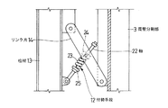
対向する周壁分割部3、4は、脱型時に内方かつ下方に移動し、周壁分割部5は内側方向に移動し、周壁分割部6は台座41及び外型30に固定されており移動しない。内型1の内部(中心部)には柱材13が垂直に設けられている。図11に示すように、柱材13はH形鋼に補強材や補助材を溶接したもので、固定の周壁分割部6の内側に突出形成した複数段の支持板21(図10)に溶接固定して支持されている。対向する周壁分割部3、4は、各々柱材13に複数段のリンク片14を介して支持されている。すなわち、各リンク片14の一端は周壁分割部3又は4に回動自在に枢着され、他端は柱材13に回動自在に枢着されている。最下段のリンク片には、周壁分割部3、4が内方かつ下方に移動するとき、これに抵抗する方向に付勢する付勢手段12が設けられている。図12に示すように、付勢手段12は軸22、コイルバネ23、滑り軸受24などからなり、一組のリンク片14の間に設けられている。軸22の一端は柱材13に回動自在に枢着され、他端側は滑り軸受24に摺動自在に支持されている。滑り軸受24は中央に軸22が通る穴が、両側にピンが形成され、そのピンが両側のリンク片に軸着されて回転自在となっている。軸22の周囲で、滑り軸受24とストッパ25の間にコイルばね23が設けられており、周壁分割部3又は4が内方かつ下方に移動するとき、これに抵抗する方向に周壁分割部3又は4を付勢する。
Opposing peripheral
対向する周壁分割部3、4の移動手段はクランプ15である。クランプ15は作動軸16、回動片17、連結部材18からなる。作動軸16は柱材13に突出形成した軸受片19に回転自在に軸着され、水平方向に向けて回転自在に支持されている。回動片17は作動軸16に溶接固定されて作動軸16の回転と共に回動する。連結部材18は一端がU字状に形成された棒状をなし、U字状をなす先端が回動片17にピンによって枢着され、他端が移動対象である周壁分割部3又は4に、その内面に突出形成された突出片20を介して、ピンによって枢着されている。周壁分割部5の移動手段はボルト26である。ボルト26を回転すると、底型40を反力として周壁分割部5を内側方向又は外側方向に移動させることができる。
The moving means of the opposed peripheral
脱型(コンクリート製品の取り出し)に際して内型1を縮径するには、図5の組立状態から、先ず周壁分割部3を、クランプ15の作動軸16を回転させて、内方かつ下方に移動させる。作動軸16を少し回転すると周壁分割部3の自重でその後は自然に移動するが、付勢手段12の作用でゆっくりと移動する。次に、同様に周壁分割部4を、クランプ15の作動軸16を回転させて、内方かつ下方に移動させる。図7はこの状態(縮径状態)の説明図で、外側の二点鎖線が組立状態の内型の大きさを表している。更にボルト26を回転させて周壁分割部5を内側方向に移動させる。図4はこの状態の平面図で、外側の一点鎖線が組立状態の内型の大きさを表している。このように、本発明においては、脱型に際して周壁のみならず天板も縮径される。脱型後、内型1を組み立てるには、上記の脱型時と反対の作業を行えばよい。すなわち、先ずボルト26を回転して周壁分割部5を内側方向に移動させ、作動軸16を回転して周壁分割部4を外方かつ上方に移動させ、最後に作動軸16を回転して周壁分割部3を外方かつ上方に移動させると、図5の組立状態に復帰する。この場合、周壁分割部3、4を外方かつ上方に移動させる操作は、付勢手段12の作用で容易に行うことができる。
In order to reduce the diameter of the inner mold 1 at the time of demolding (removal of concrete product), the peripheral wall dividing section 3 is first moved inward and downward by rotating the operating
本発明において、内型の形状は四角筒状に限らず、円筒状、多角形筒状などとすることができる。また、天板は4つに限らず、それ以上に分割することが可能である。図13に示す内型50は、周壁が周壁分割部51、52、53、54の4つに分割され、天板が天板分割部55、56、57、58、59の5つに分割されている。天板分割部55は周壁分割部51に、天板分割部56は周壁分割部52に、天板分割部57は周壁分割部53に、天板分割部58は周壁分割部54に対応する。中央の天板分割部59は、いずれの周壁分割部に対応しておらず、周囲の天板分割部によって支持されている。このように天板を5つ以上に分割しても、内型の縮径には支障がない。
In the present invention, the shape of the inner mold is not limited to a square tube shape, but may be a cylindrical shape, a polygonal tube shape, or the like. Moreover, the top plate is not limited to four and can be divided into more than that. In the inner mold 50 shown in FIG. 13, the peripheral wall is divided into four peripheral
1 内型
2 周壁
3 周壁分割部
4 周壁分割部
5 周壁分割部
6 周壁分割部
7 天板
8 天板分割部
9 天板分割部
10 天板分割部
11 天板分割部
12 付勢手段
13 柱材
14 リンク片
15 クランプ
16 作動軸
17 回動片
18 連結部材
19 軸受片
20 突出片
21 支持板
22 軸
23 コイルバネ
24 滑り軸受
25 ストッパ
26 ボルト
30 外型
31 脚部
32 ボルト
40 底型
41 台座
42 レール
43 キャビティー
50 内型
51 周壁分割部
52 周壁分割部
53 周壁分割部
54 周壁分割部
55 天板分割部
56 天板分割部
57 天板分割部
58 天板分割部
59 天板分割部
DESCRIPTION OF SYMBOLS 1
Claims (4)
前記周壁が縦に4つの周壁分割部に分割されるとともに、該4つの周壁分割部に対応して天板が少なくとも4つの天板分割部に分割され、
前記対応する周壁分割部と天板分割部とが一体化されており、
前記周壁分割部のうちの対向する2つの周壁分割部が内方かつ下方に移動し、残りの2つの周壁分割部のうちの少なくとも1つが内側方向に移動することで周壁及び天板を縮径して筒状コンクリート製品を脱型する内型であって、
前記周壁の内部に柱材を設け、該柱材に前記対向する2つの周壁分割部を、それぞれ縦方向に複数配設したリンク片を介して接合し、該リンク片が回動することにより、前記周壁分割部がガイドされて内方かつ下方に平行移動することを特徴とする筒状コンクリート製品成形用型枠の内型。 The upper end of the cylindrical peripheral wall is closed with a top plate,
The peripheral wall is vertically divided into four peripheral wall division parts, and the top plate is divided into at least four top plate division parts corresponding to the four peripheral wall division parts,
The corresponding peripheral wall dividing portion and the top plate dividing portion are integrated,
The two peripheral wall dividing portions facing each other out of the peripheral wall dividing portions move inward and downward, and at least one of the remaining two peripheral wall dividing portions moves inward, thereby reducing the diameter of the peripheral wall and the top plate. Then, it is an inner mold that demolds the cylindrical concrete product ,
A column member is provided inside the peripheral wall, and the two peripheral wall dividing portions facing each other are joined to the column member via a plurality of link pieces arranged in the vertical direction, and the link piece rotates, An inner mold for forming a cylindrical concrete product, wherein the peripheral wall dividing portion is guided and translated inward and downward .
Priority Applications (1)
| Application Number | Priority Date | Filing Date | Title |
|---|---|---|---|
| JP2005039067A JP4448460B2 (en) | 2005-02-16 | 2005-02-16 | Inner mold of mold for molding cylindrical concrete products |
Applications Claiming Priority (1)
| Application Number | Priority Date | Filing Date | Title |
|---|---|---|---|
| JP2005039067A JP4448460B2 (en) | 2005-02-16 | 2005-02-16 | Inner mold of mold for molding cylindrical concrete products |
Publications (3)
| Publication Number | Publication Date |
|---|---|
| JP2006224372A JP2006224372A (en) | 2006-08-31 |
| JP2006224372A5 JP2006224372A5 (en) | 2007-02-22 |
| JP4448460B2 true JP4448460B2 (en) | 2010-04-07 |
Family
ID=36986150
Family Applications (1)
| Application Number | Title | Priority Date | Filing Date |
|---|---|---|---|
| JP2005039067A Active JP4448460B2 (en) | 2005-02-16 | 2005-02-16 | Inner mold of mold for molding cylindrical concrete products |
Country Status (1)
| Country | Link |
|---|---|
| JP (1) | JP4448460B2 (en) |
Cited By (1)
| Publication number | Priority date | Publication date | Assignee | Title |
|---|---|---|---|---|
| CN109252456A (en) * | 2018-10-31 | 2019-01-22 | 中国冶集团有限公司 | Continuous rigid frame bridge box girder inner formwork regulating device based on Hanging Basket cantilever technique |
Families Citing this family (4)
| Publication number | Priority date | Publication date | Assignee | Title |
|---|---|---|---|---|
| JP5701366B1 (en) * | 2013-11-22 | 2015-04-15 | 旭コンクリート工業株式会社 | Form for bottomed concrete product and method for demolding bottomed concrete product |
| CN108908662B (en) * | 2018-06-25 | 2020-07-10 | 北京中兴恒工程咨询有限公司 | Chiseling-free construction mold for prefabricated hollow slab beam |
| CN111037718A (en) * | 2019-12-31 | 2020-04-21 | 广西建工集团第五建筑工程有限责任公司 | Interior-free integral quick-dismantling box girder inner mold and mounting and dismounting method thereof |
| CN113954230A (en) * | 2021-10-28 | 2022-01-21 | 浙江交工集团股份有限公司 | Processing method of prefabricated hollow pier |
-
2005
- 2005-02-16 JP JP2005039067A patent/JP4448460B2/en active Active
Cited By (2)
| Publication number | Priority date | Publication date | Assignee | Title |
|---|---|---|---|---|
| CN109252456A (en) * | 2018-10-31 | 2019-01-22 | 中国冶集团有限公司 | Continuous rigid frame bridge box girder inner formwork regulating device based on Hanging Basket cantilever technique |
| CN109252456B (en) * | 2018-10-31 | 2020-10-20 | 中国一冶集团有限公司 | Continuous rigid frame bridge box girder inner mold adjusting device based on hanging basket suspension casting process |
Also Published As
| Publication number | Publication date |
|---|---|
| JP2006224372A (en) | 2006-08-31 |
Similar Documents
| Publication | Publication Date | Title |
|---|---|---|
| JP4448460B2 (en) | Inner mold of mold for molding cylindrical concrete products | |
| US20120058214A1 (en) | Multiple press molding machine | |
| JP2004276553A (en) | Injection molding machine | |
| JP3706096B2 (en) | Form for forming cylindrical concrete products | |
| JP4629632B2 (en) | Form for forming cylindrical concrete product and its inner mold | |
| JP2008238411A (en) | Form device for molding concrete product | |
| JP2008302537A (en) | Mold structure and its pushing-out/pulling-out method | |
| JP2007092310A (en) | Inner form structure | |
| JP2011148220A (en) | Clamping mechanism for lifting spacer member in core of concrete formwork | |
| RU2005140802A (en) | STAMP FOR SEPARATORY OPERATIONS WITH A PERFORATION STEP SYNCHRONIZER | |
| US869828A (en) | Building-block mold. | |
| KR101798538B1 (en) | Lego Type Cart Supporting Post | |
| JP4542955B2 (en) | Vertical injection molding machine | |
| US892583A (en) | Cement-block machine. | |
| JP3141359U (en) | Core support device for hollow concrete molded products | |
| JP3054085U (en) | Press machine bed | |
| JP3764464B2 (en) | Molding mechanism of molding machine | |
| US987499A (en) | Mold for concrete posts. | |
| JP2011011243A (en) | Wedge type adjusting mechanism | |
| JPH069913U (en) | Movable mechanism in the inner frame of concrete formwork | |
| JP3002617B2 (en) | Core device for formwork for culvert block production | |
| US1030094A (en) | Cement block and brick machine. | |
| USRE12626E (en) | Supporting-stand and mold for making building-blocks | |
| US763634A (en) | Machine for forming building-blocks. | |
| JP5920999B2 (en) | Formwork for gutter construction |
Legal Events
| Date | Code | Title | Description |
|---|---|---|---|
| A621 | Written request for application examination |
Free format text: JAPANESE INTERMEDIATE CODE: A621 Effective date: 20061120 |
|
| A521 | Request for written amendment filed |
Free format text: JAPANESE INTERMEDIATE CODE: A523 Effective date: 20061120 |
|
| A977 | Report on retrieval |
Free format text: JAPANESE INTERMEDIATE CODE: A971007 Effective date: 20090723 |
|
| A131 | Notification of reasons for refusal |
Free format text: JAPANESE INTERMEDIATE CODE: A131 Effective date: 20090818 |
|
| A521 | Request for written amendment filed |
Free format text: JAPANESE INTERMEDIATE CODE: A523 Effective date: 20090918 |
|
| TRDD | Decision of grant or rejection written | ||
| A01 | Written decision to grant a patent or to grant a registration (utility model) |
Free format text: JAPANESE INTERMEDIATE CODE: A01 Effective date: 20100119 |
|
| A01 | Written decision to grant a patent or to grant a registration (utility model) |
Free format text: JAPANESE INTERMEDIATE CODE: A01 |
|
| A61 | First payment of annual fees (during grant procedure) |
Free format text: JAPANESE INTERMEDIATE CODE: A61 Effective date: 20100122 |
|
| FPAY | Renewal fee payment (event date is renewal date of database) |
Free format text: PAYMENT UNTIL: 20130129 Year of fee payment: 3 |
|
| R150 | Certificate of patent or registration of utility model |
Ref document number: 4448460 Country of ref document: JP Free format text: JAPANESE INTERMEDIATE CODE: R150 |
|
| FPAY | Renewal fee payment (event date is renewal date of database) |
Free format text: PAYMENT UNTIL: 20130129 Year of fee payment: 3 |
|
| R250 | Receipt of annual fees |
Free format text: JAPANESE INTERMEDIATE CODE: R250 |
|
| R250 | Receipt of annual fees |
Free format text: JAPANESE INTERMEDIATE CODE: R250 |
|
| R250 | Receipt of annual fees |
Free format text: JAPANESE INTERMEDIATE CODE: R250 |
|
| R250 | Receipt of annual fees |
Free format text: JAPANESE INTERMEDIATE CODE: R250 |
|
| R250 | Receipt of annual fees |
Free format text: JAPANESE INTERMEDIATE CODE: R250 |
|
| R250 | Receipt of annual fees |
Free format text: JAPANESE INTERMEDIATE CODE: R250 |
|
| R250 | Receipt of annual fees |
Free format text: JAPANESE INTERMEDIATE CODE: R250 |
|
| R250 | Receipt of annual fees |
Free format text: JAPANESE INTERMEDIATE CODE: R250 |
|
| R250 | Receipt of annual fees |
Free format text: JAPANESE INTERMEDIATE CODE: R250 |
|
| R250 | Receipt of annual fees |
Free format text: JAPANESE INTERMEDIATE CODE: R250 |
|
| R250 | Receipt of annual fees |
Free format text: JAPANESE INTERMEDIATE CODE: R250 |
|
| R250 | Receipt of annual fees |
Free format text: JAPANESE INTERMEDIATE CODE: R250 |