JP4448077B2 - Bowl inner bag and bowl - Google Patents
Bowl inner bag and bowl Download PDFInfo
- Publication number
- JP4448077B2 JP4448077B2 JP2005271561A JP2005271561A JP4448077B2 JP 4448077 B2 JP4448077 B2 JP 4448077B2 JP 2005271561 A JP2005271561 A JP 2005271561A JP 2005271561 A JP2005271561 A JP 2005271561A JP 4448077 B2 JP4448077 B2 JP 4448077B2
- Authority
- JP
- Japan
- Prior art keywords
- inner bag
- ball
- reinforcing
- chamber
- electronic device
- Prior art date
- Legal status (The legal status is an assumption and is not a legal conclusion. Google has not performed a legal analysis and makes no representation as to the accuracy of the status listed.)
- Active
Links
- 230000003014 reinforcing effect Effects 0.000 claims abstract description 56
- 239000000463 material Substances 0.000 claims description 31
- 239000000835 fiber Substances 0.000 claims description 17
- 239000004816 latex Substances 0.000 claims description 14
- 229920000126 latex Polymers 0.000 claims description 14
- 238000000465 moulding Methods 0.000 claims description 12
- 229920003023 plastic Polymers 0.000 claims description 10
- 239000004033 plastic Substances 0.000 claims description 10
- 238000003780 insertion Methods 0.000 claims description 3
- 230000037431 insertion Effects 0.000 claims description 3
- 241000255925 Diptera Species 0.000 claims 3
- 238000004519 manufacturing process Methods 0.000 description 17
- 229920002803 thermoplastic polyurethane Polymers 0.000 description 14
- 230000001133 acceleration Effects 0.000 description 13
- 239000010408 film Substances 0.000 description 11
- 238000000034 method Methods 0.000 description 11
- 210000003491 skin Anatomy 0.000 description 7
- 230000000694 effects Effects 0.000 description 6
- 230000004044 response Effects 0.000 description 5
- 230000008901 benefit Effects 0.000 description 4
- 230000006698 induction Effects 0.000 description 4
- 239000007788 liquid Substances 0.000 description 4
- 239000002184 metal Substances 0.000 description 4
- 230000008569 process Effects 0.000 description 4
- 239000000243 solution Substances 0.000 description 4
- 239000000725 suspension Substances 0.000 description 4
- 239000004760 aramid Substances 0.000 description 3
- 229920006231 aramid fiber Polymers 0.000 description 3
- 239000007789 gas Substances 0.000 description 3
- 238000002347 injection Methods 0.000 description 3
- 239000007924 injection Substances 0.000 description 3
- 230000004048 modification Effects 0.000 description 3
- 238000012986 modification Methods 0.000 description 3
- 238000012545 processing Methods 0.000 description 3
- 230000002787 reinforcement Effects 0.000 description 3
- 238000007493 shaping process Methods 0.000 description 3
- 238000003860 storage Methods 0.000 description 3
- 238000003466 welding Methods 0.000 description 3
- 230000003139 buffering effect Effects 0.000 description 2
- 230000001419 dependent effect Effects 0.000 description 2
- 238000010586 diagram Methods 0.000 description 2
- 238000009826 distribution Methods 0.000 description 2
- 210000002615 epidermis Anatomy 0.000 description 2
- 230000006870 function Effects 0.000 description 2
- 230000006872 improvement Effects 0.000 description 2
- 238000002844 melting Methods 0.000 description 2
- 230000008018 melting Effects 0.000 description 2
- 230000035939 shock Effects 0.000 description 2
- 230000006641 stabilisation Effects 0.000 description 2
- 238000011105 stabilization Methods 0.000 description 2
- 238000012360 testing method Methods 0.000 description 2
- XLYOFNOQVPJJNP-UHFFFAOYSA-N water Substances O XLYOFNOQVPJJNP-UHFFFAOYSA-N 0.000 description 2
- 241000239290 Araneae Species 0.000 description 1
- 229920001494 Technora Polymers 0.000 description 1
- 239000006096 absorbing agent Substances 0.000 description 1
- 239000004676 acrylonitrile butadiene styrene Substances 0.000 description 1
- 238000004026 adhesive bonding Methods 0.000 description 1
- 230000002411 adverse Effects 0.000 description 1
- 230000008859 change Effects 0.000 description 1
- 239000011248 coating agent Substances 0.000 description 1
- 238000000576 coating method Methods 0.000 description 1
- 238000004891 communication Methods 0.000 description 1
- 229920001577 copolymer Polymers 0.000 description 1
- 238000007598 dipping method Methods 0.000 description 1
- 230000005672 electromagnetic field Effects 0.000 description 1
- 239000006260 foam Substances 0.000 description 1
- 239000003365 glass fiber Substances 0.000 description 1
- 238000001746 injection moulding Methods 0.000 description 1
- 239000011344 liquid material Substances 0.000 description 1
- 238000005259 measurement Methods 0.000 description 1
- 230000007246 mechanism Effects 0.000 description 1
- 239000000203 mixture Substances 0.000 description 1
- 238000010248 power generation Methods 0.000 description 1
- 230000009993 protective function Effects 0.000 description 1
- 239000012783 reinforcing fiber Substances 0.000 description 1
- 238000007665 sagging Methods 0.000 description 1
- 238000007789 sealing Methods 0.000 description 1
- 239000007787 solid Substances 0.000 description 1
- 239000002904 solvent Substances 0.000 description 1
- 230000000087 stabilizing effect Effects 0.000 description 1
- 239000004950 technora Substances 0.000 description 1
- 238000003856 thermoforming Methods 0.000 description 1
- 239000012815 thermoplastic material Substances 0.000 description 1
- 239000010409 thin film Substances 0.000 description 1
- 239000001993 wax Substances 0.000 description 1
Images


Classifications
-
- A—HUMAN NECESSITIES
- A63—SPORTS; GAMES; AMUSEMENTS
- A63B—APPARATUS FOR PHYSICAL TRAINING, GYMNASTICS, SWIMMING, CLIMBING, OR FENCING; BALL GAMES; TRAINING EQUIPMENT
- A63B43/00—Balls with special arrangements
- A63B43/007—Arrangements on balls for connecting lines or cords
-
- A—HUMAN NECESSITIES
- A63—SPORTS; GAMES; AMUSEMENTS
- A63B—APPARATUS FOR PHYSICAL TRAINING, GYMNASTICS, SWIMMING, CLIMBING, OR FENCING; BALL GAMES; TRAINING EQUIPMENT
- A63B41/00—Hollow inflatable balls
- A63B41/02—Bladders
-
- A—HUMAN NECESSITIES
- A63—SPORTS; GAMES; AMUSEMENTS
- A63B—APPARATUS FOR PHYSICAL TRAINING, GYMNASTICS, SWIMMING, CLIMBING, OR FENCING; BALL GAMES; TRAINING EQUIPMENT
- A63B43/00—Balls with special arrangements
-
- A—HUMAN NECESSITIES
- A63—SPORTS; GAMES; AMUSEMENTS
- A63B—APPARATUS FOR PHYSICAL TRAINING, GYMNASTICS, SWIMMING, CLIMBING, OR FENCING; BALL GAMES; TRAINING EQUIPMENT
- A63B41/00—Hollow inflatable balls
- A63B2041/005—Hollow inflatable balls with counterweight for adjusting the centre of gravity
-
- A—HUMAN NECESSITIES
- A63—SPORTS; GAMES; AMUSEMENTS
- A63B—APPARATUS FOR PHYSICAL TRAINING, GYMNASTICS, SWIMMING, CLIMBING, OR FENCING; BALL GAMES; TRAINING EQUIPMENT
- A63B2225/00—Miscellaneous features of sport apparatus, devices or equipment
- A63B2225/50—Wireless data transmission, e.g. by radio transmitters or telemetry
-
- A—HUMAN NECESSITIES
- A63—SPORTS; GAMES; AMUSEMENTS
- A63B—APPARATUS FOR PHYSICAL TRAINING, GYMNASTICS, SWIMMING, CLIMBING, OR FENCING; BALL GAMES; TRAINING EQUIPMENT
- A63B71/00—Games or sports accessories not covered in groups A63B1/00 - A63B69/00
- A63B71/06—Indicating or scoring devices for games or players, or for other sports activities
- A63B71/0605—Decision makers and devices using detection means facilitating arbitration
Abstract
Description
本発明は、膨らませるボール、特にサッカーボールのための内袋に関する。 The present invention relates to an inner bag for an inflatable ball, in particular a soccer ball.
サッカー、ハンドボールまたはバレーボールなどの多くのスポーツにおいて、試合を観戦している人のために、追加の情報を提供することが望ましい。これは、例えば、試合時間の任意の時点でのプレーヤーやボールの位置、またはボールの速度および個々のプレーヤーの速さと能力についての情報に関する。審判や、試合で規則が遵守されていることを監視する他の人々も、そのような情報から恩恵を受け、試合をより確実に管理するであろう。最後に、トレーナーや、競技者の医療スタッフの観点から、フィールド上の出来事を観察するだけでなく、試合の正確な過程についての信頼できるデータを得ることも道理に適っている。 In many sports, such as soccer, handball or volleyball, it is desirable to provide additional information for those watching the game. This relates, for example, to information about the position of the player or ball at any point in the game time, or the speed of the ball and the speed and ability of the individual player. Referees and other people who monitor compliance with the rules will also benefit from such information and will better manage the match. Finally, from the perspective of trainers and competitor medical staff, it makes sense not only to observe events on the field, but also to obtain reliable data about the exact process of the match.
したがって、近年、送信器がボール内に配置され、ことによるとさらに他の送信器がプレーヤーに取り付けられ、それらの送信器が電磁波や他の信号を発したり反射したりするいくつかの方法が提案されている。これらの信号は、適切に設置された受信機により捕らえられ、試合時間の任意の時点で、物体、例えば、ボールの位置や速度に関する所望の情報を提供できる。そのような追跡システムの例が、特許文献1から6より知られている。 Therefore, in recent years, several methods have been proposed in which transmitters are placed in a ball and possibly other transmitters are attached to the player, and these transmitters emit and reflect electromagnetic waves and other signals. Has been. These signals are captured by a properly installed receiver and can provide the desired information regarding the position and velocity of an object, such as a ball, at any point in the game time. Examples of such tracking systems are known from US Pat.
そのような追跡システムの絶対的に必要な事項は、ボール内に送信器またはリフレクタを確実かつ永久的に配置することである。このことは、サッカーボールなどの膨らませる内袋を有する大きなボールの場合、特に、重大な問題である。中に送信器を吊り下げて、第1に、電子部品の損傷を避けるために、ボールの変形や加速の下で生じる機械的負荷を緩衝すべきである。さらに、挿入された送信器は、ボールの力学的性質および軌道に影響を与えないことが好ましい。最後に、多くの用途で、ボールの中心がいつ特定のライン、例えば、サッカーのゴールのゴールラインを通過したかに関して正確な判定が必要とされる。したがって、送信器は、ボール内の正確に定義された位置を取り、その位置を永久的に維持すべきである。 The absolute requirement of such a tracking system is a reliable and permanent placement of the transmitter or reflector in the ball. This is a particularly serious problem for large balls having an inflatable inner bag such as a soccer ball. The transmitter should be suspended inside and, first, to avoid damage to the electronic components, the mechanical loads that occur under ball deformation and acceleration should be buffered. Furthermore, the inserted transmitter preferably does not affect the ball's mechanical properties and trajectory. Finally, in many applications, an accurate determination is required as to when the center of the ball has passed a particular line, such as a goal line of a soccer goal. Therefore, the transmitter should take a precisely defined position within the ball and maintain that position permanently.
この問題を解決するための従来技術から知られている手法は、これまで、送信器またはそれに相当するデバイスが、ボールの内袋の内部にいくつかの弾性ワイヤまたは同様の装置によって自由に吊り下げられる構成のみに関する。そのような配置は、例えば、既に述べた特許文献6および特許文献7から9より知られている。同様の構成が、特許文献10および11より知られており、これら最後の二つの文献は、ボールの内部に永久的に配置された他のデバイスに関するものである。 In the past, techniques known from the prior art for solving this problem have been described in which a transmitter or equivalent device is freely suspended by a number of elastic wires or similar devices inside the inner bag of the ball. Only relevant configuration. Such an arrangement is known, for example, from the already mentioned patent documents 6 and 7 to 9. Similar arrangements are known from US Pat. Nos. 5,047,086 and 5, and these last two documents relate to other devices that are permanently placed inside the ball.
しかしながら、現在公知の解決策には、いつくかの理由のために欠点がある。一方では、従来技術に開示された内袋とそれに対応するボールを製造することは非常に難しく、それには、多数の手作業の加工段階が必要である。他方で、これまでに知られている内袋は、敏感な電子部品を損傷から永久的に保護するために要求される安定性を持ち合わせていない。さらに、現在まで、ボールの中心に電子部品を確実に永久的に配置することは達成できていない。 However, currently known solutions have drawbacks for several reasons. On the one hand, it is very difficult to manufacture the inner bag and the corresponding ball disclosed in the prior art, which requires a number of manual processing steps. On the other hand, the inner bags known so far do not have the stability required to permanently protect sensitive electronic components from damage. Furthermore, to date, it has not been possible to reliably and permanently place the electronic component in the center of the ball.
内袋自体の安定性を増加させるための手法が特許文献12および13から知られている。しかしながら、これらの文献は、ボールの(例えば、それぞれ、一般的な球形状を持つ正確に丸いボールまたは多面形ボールの)形状安定性のみに関し、内袋の内部における安定性を改善するための、または敏感なデバイスを適切に吊り下げるための手がかりは全く提供していない。
したがって、本発明の課題は、送信器または別の電子デバイスを所定の位置に維持でき、デバイスの損傷を防ぐために、発生する負荷を十分に緩衝する膨らませるボール、特にサッカーボールを提供することにある。さらに別の態様によれば、内袋は、製造が費用効果的であり、ボールの他の性質に悪影響を与えないべきである。 Accordingly, it is an object of the present invention to provide an inflatable ball, particularly a soccer ball, that can maintain a transmitter or another electronic device in place and sufficiently cushion the generated load to prevent damage to the device. is there. According to yet another aspect, the inner bag should be cost effective to manufacture and should not adversely affect other properties of the ball.
本発明の第1の態様によれば、この課題は、膨らませるボール、特にサッカーボール用の内袋であって、内袋の内部に延在する少なくとも二つの補強平面、および内袋の内部に配置され、補強平面によって所定の位置に維持される少なくとも一つの電子デバイスを有してなる内袋により解決される。 According to the first aspect of the present invention, this problem is an inner bag for an inflatable ball, in particular a soccer ball, which has at least two reinforcing planes extending inside the inner bag, and an inner bag. Solved by an inner bag comprising at least one electronic device that is arranged and maintained in place by a reinforcing plane.
上述した従来技術とは反対に、本発明の第1の態様による電子デバイスは、伝達できるのが引張力のみにとどまらない要素により配置される。電子デバイスが所定の位置から外れたときに、補強平面が追加の剪断力を提供する。さらに、補強平面は、そのどのような動きによっても内袋内部の気積が変わるので、デバイスに生じる振動を、油圧式緩衝器のように緩和する。したがって、例えば、本発明による内袋を有するサッカーボールが、プレーヤーの鋭いキックによって最初に著しく変形し、これにより、デバイスが元の位置から実質的に外れたときに、内袋は、元の外形だけでなく、内部の元の構造を迅速に回復することが補強平面により確実になる。 Contrary to the prior art described above, the electronic device according to the first aspect of the present invention is arranged by elements that can only transmit tension. The reinforcing plane provides additional shear when the electronic device is out of position. Furthermore, since the air volume inside the inner bag is changed by any movement of the reinforcing plane, the vibration generated in the device is mitigated like a hydraulic shock absorber. Thus, for example, a soccer ball having an inner bag according to the present invention is initially significantly deformed by a player's sharp kick, so that when the device is substantially out of its original position, the inner bag Not only does the reinforcing plane ensure that the original internal structure is quickly restored.
さらに別の利点は、内袋の内部にある補強平面により決定される上述した気積によって電子デバイスに作用する加速力のより効果的な緩衝である。これにより、電子デバイスへの機械的負荷が減少し、それによって、デバイスの寿命が増加する。 Yet another advantage is a more effective buffering of the acceleration forces acting on the electronic device due to the above-mentioned air volume determined by the reinforcing plane inside the inner bag. This reduces the mechanical load on the electronic device, thereby increasing the lifetime of the device.
電子デバイスは内袋の実質的に中心に配置されることが好ましい。さらに、このデバイスは、少なくとも二つの補強平面の交線に配置されることが好ましい。そのように配置によって、電子デバイスが中心から外れたときに、いくつかの補強平面が復元力を提供することが確実になる。 It is preferable that the electronic device is disposed substantially at the center of the inner bag. Furthermore, the device is preferably arranged at the intersection of at least two reinforcing planes. Such an arrangement ensures that several reinforcing planes provide a restoring force when the electronic device is off-center.
少なくとも二つの補強平面の交線は、内袋の中心から外側に実質的に半径方向に延在する。この少なくとも二つの補強平面は、90°ではない角度で交差することが好ましい。現在特に好ましい実施の形態において、内袋は少なくとも二つの交線を有しており、交線が実質的に120°の角度を画成することが好ましい。交線と内袋の外面との接点が実質的に正四面体を画成することが好ましい。この配置により、限られた数の内部の補強平面による低重量と高度の安定性とが組み合わせられる。 The line of intersection of the at least two reinforcing planes extends substantially radially outward from the center of the inner bag. The at least two reinforcing planes preferably intersect at an angle other than 90 °. In the presently particularly preferred embodiment, the inner bag has at least two intersecting lines, and it is preferred that the intersecting lines define an angle of substantially 120 °. Preferably, the contact point between the intersection line and the outer surface of the inner bag substantially defines a regular tetrahedron. This arrangement combines a low weight with a limited number of internal reinforcing planes and a high degree of stability.
本発明による内袋の別の特に安定な実施の形態において、補強平面が内袋の外面に接触する線は、膨らませるボールの表皮の少なくとも一つのパネルの形状に実質的に対応する。 In another particularly stable embodiment of the inner bag according to the invention, the line where the reinforcing plane contacts the outer surface of the inner bag substantially corresponds to the shape of at least one panel of the inflatable ball skin.
少なくとも一つの補強平面は、内袋の内圧を等しくするための少なくとも一つの開口部を有することが好ましく、この開口部は、ある実施の形態において、補強平面の実質的に中心に配置されている。 The at least one reinforcing plane preferably has at least one opening for equalizing the inner pressure of the inner bag, and in one embodiment, the opening is located substantially at the center of the reinforcing plane. .
補強平面は、内袋の外面に接触しない一つ以上の補助平面を有してなることが好ましい。この補助平面は、少なくとも一つの電子デバイスがその中に配置される内部体積を決定することが好ましい。この内部体積は、電子デバイスのための追加の緩衝保護を提供し、デバイスの所定の位置からのずれを制限する。 It is preferable that the reinforcing plane has one or more auxiliary planes that do not contact the outer surface of the inner bag. This auxiliary plane preferably determines the internal volume in which at least one electronic device is placed. This internal volume provides additional buffer protection for the electronic device and limits the deviation of the device from a predetermined position.
さらに別の態様によれば、本発明は、膨らませるボール、特にサッカーボール用の内袋であって、内袋の内部に配置された少なくとも一つの電子デバイスおよびこのデバイスを内袋の内部の所定の位置に維持するために配置された複数の引張要素を有してなり、このデバイスは内袋の内部にある別個のチャンバ内に配置されることが好ましい内袋に関する。 According to yet another aspect, the present invention provides an inner bag for an inflatable ball, in particular a soccer ball, comprising at least one electronic device disposed inside the inner bag and the device within the inner bag. The inner bag preferably comprises a plurality of tension elements arranged to maintain the position of the inner bag, the device preferably being placed in a separate chamber inside the inner bag.
好ましいチャンバは、電子デバイスの敏感な部品のための追加の保護を提供する。これは、使用に際してだけでなく、デバイスを最初に内袋中に挿入し、緩衝の吊り下げによって衝撃や他の機械的負荷に対してまだ保護されていないときの組立てに際しても当てはまる。 Preferred chambers provide additional protection for sensitive parts of electronic devices. This applies not only in use, but also during assembly when the device is first inserted into the inner bag and is not yet protected against shocks and other mechanical loads by buffer suspension.
第1の実施の形態において、チャンバは、複数の引張要素の間に延在する複数の補助平面により画成される。その結果、追加の別の空気緩衝が電子デバイスの周りに形成され、改善された緩衝効果が提供される。 In the first embodiment, the chamber is defined by a plurality of auxiliary planes extending between the plurality of tension elements. As a result, an additional separate air buffer is formed around the electronic device to provide an improved buffering effect.
さらに現在好ましい実施の形態において、チャンバは丸い形状を有し、この形状は実質的に球であることが好ましい。そのような形状は、発生する機械的負荷に対して最大の保護を提供する。内袋が極端に変形したとき、例えば、サッカーボールのペナルティー・キックのとき、外面が、デバイスの所定の位置を超えて変形した場合、チャンバの丸い形状は、発生する衝撃が、チャンバを好ましくは側方にそらし、敏感な電子デバイスを破壊し得る部品の最大加速を生じないことを確実にする。 Further, in the presently preferred embodiment, the chamber has a round shape, which is preferably substantially spherical. Such a shape provides maximum protection against the mechanical loads that occur. When the inner bag is extremely deformed, e.g. in the case of a soccer ball penalty kick, if the outer surface is deformed beyond a predetermined position of the device, the round shape of the chamber preferably causes the impact generated to Turn to the side to ensure that there is no maximum acceleration of parts that can destroy sensitive electronic devices.
さらに、球形状は、内袋内部の重量分布に最大の対称性を持たせ、したがって、ボールの力学的性質および飛行経路への影響をできるだけ少なくする。最後に、チャンバの丸い形状により、ボールが極端に変形した最中に内袋の壁の内面とチャンバとが接触した場合、内袋への損傷を防ぐ。 In addition, the spherical shape has the greatest symmetry in the weight distribution inside the inner bag, thus minimizing the impact on the ball's mechanical properties and flight path. Finally, the round shape of the chamber prevents damage to the inner bag if the inner surface of the inner bag wall contacts the chamber during extreme deformation of the ball.
複数の引張要素の少なくとも一つが、その引張要素を、内袋の外面および/またはデバイスまたはチャンバにしっかりと固定するために、一端で、搭載手段を有してなることが好ましい。この少なくとも一つの引張要素は繊維の束を有してなり、搭載手段は、繊維の束の周りに射出成形されたプラスチック材料から構成される。そのような搭載手段は比較的容易に製造でき、内袋内部のチャンバ/デバイスの最終的な組立てが容易になる。 Preferably, at least one of the plurality of tension elements comprises mounting means at one end to secure the tension element to the outer surface of the inner bag and / or the device or chamber. The at least one tensile element comprises a bundle of fibers and the mounting means is composed of a plastic material that is injection molded around the bundle of fibers. Such mounting means are relatively easy to manufacture and facilitate final assembly of the chamber / device inside the inner bag.
繊維の束は、>500N、好ましくは>1000N、特に好ましくは>1200Nの短期引張強度を有する。しかしながら、500N未満の値も一般には可能である。ホイールのスポークと同様に、より高い引張強度が、引張要素のより高い予備張力を可能にし、これは転じて、内袋内のデバイスをより安定に配置することになる。 The bundle of fibers has a short-term tensile strength of> 500N, preferably> 1000N, particularly preferably> 1200N. However, values below 500 N are generally possible. Similar to the spokes of the wheel, the higher tensile strength allows for higher pretensioning of the tensile element, which in turn will place the device in the inner bag more stably.
費用効率的な製造のために、さらに、引張要素が十分な耐熱性を有することが好ましい。これにより、引張要素と、必要であれば、デバイスとを、製造の最終的な成形工程の前に内袋の内部に挿入することができる。 For cost-effective production, it is further preferred that the tensile element has sufficient heat resistance. This allows the tension element and, if necessary, the device to be inserted inside the inner bag before the final molding step of manufacture.
最後に、本発明は、さらに別の態様によると、膨らませるボール、特にサッカーボール用の内袋であって、複数の中空支柱を有してなる内袋に関する。内袋を膨らませるときに、中空支柱は、内袋の外側から内部に半径方向に延在し、内袋の実質的に中心に、空洞を画成する。さらに、内袋は、空洞内に配置された少なくとも一つの電子デバイスを備え、少なくとも一つの中空支柱が、デバイスを内袋の外側から中心にこの中空に通して挿入できるような十分なサイズを有している。 Finally, according to yet another aspect, the present invention relates to an inner bag for an inflatable ball, in particular a soccer ball, comprising a plurality of hollow struts. When the inner bag is inflated, the hollow struts extend radially from the outside to the inside of the inner bag and define a cavity substantially at the center of the inner bag. In addition, the inner bag comprises at least one electronic device disposed in the cavity, and the at least one hollow strut is sufficiently sized to allow the device to be inserted through the hollow from the outside of the inner bag to the center. is doing.
そのような配置によって、デバイスを内袋中に挿入できるだけでなく、デバイスが破損した場合には、そこから取り出すことができる。デバイスを挿入するための中空支柱は、内袋の他の中空支柱とは異なるサイズを有することが好ましい。デバイスを挿入するための中空支柱が、内袋の弁開口部を受け入れるための受容部に対して対称に配されている配置が特に好ましい。その結果、内袋内の重量分布がより均一になり、内袋の挿入が与える、対応するボールの軌道への影響ができるだけ小さくなる。 With such an arrangement, not only can the device be inserted into the inner bag, but if the device breaks, it can be removed therefrom. The hollow strut for inserting the device preferably has a different size from the other hollow struts of the inner bag. Particularly preferred is an arrangement in which the hollow struts for inserting the device are arranged symmetrically with respect to the receiving part for receiving the valve opening of the inner bag. As a result, the weight distribution in the inner bag becomes more uniform, and the influence of the insertion of the inner bag on the trajectory of the corresponding ball is minimized.
ある実施の形態において、内袋は、油または水などの液体中に溶融または溶解できるコアの周りに熱可塑性材料を成形することによって製造でき、このときコアは、内袋材料を成形したときにある間隔で配置されている。その結果、電子デバイスの所定の形状とサイズのために正確に設計された比較的複雑な形状の内袋を形成できる。例えば、内袋材料が射出により施されるときに、この配置を用いてよい。あるいは、間の開いた成形コアの構成物を、内袋を形成するために、液体の内袋材料、例えば、ラテックス中に浸漬してもよい。 In certain embodiments, the inner bag can be manufactured by molding a thermoplastic material around a core that can be melted or dissolved in a liquid such as oil or water, when the core is molded into the inner bag material. They are arranged at certain intervals. As a result, it is possible to form an inner bag having a relatively complicated shape that is accurately designed for a predetermined shape and size of the electronic device. For example, this arrangement may be used when the inner bag material is applied by injection. Alternatively, the open molded core composition may be immersed in a liquid inner bag material, such as latex, to form the inner bag.
本発明による内袋の追加の都合のよい改変は、さらなる従属請求項の主題である。 Additional advantageous modifications of the inner bag according to the invention are the subject of further dependent claims.
最後に、本発明は、本発明の上述した実施の形態による内袋を有するボールに関する。ボールは、内袋とボールの表皮との間に配置されたカーカスを有することが好ましい。ボールの内袋が上述した補強平面を使用する場合、搭載ケーブルが、少なくとも一つの補強平面中に組み込まれ、電子部品とカーカスに取り付けられている。それゆえ、ボールのカーカスは、電子部品の取付けに含まれ、したがって、ボール内の正確かつ永久的な位置決めを安定化させる。 Finally, the present invention relates to a ball having an inner bag according to the above-described embodiment of the present invention. The ball preferably has a carcass disposed between the inner bag and the skin of the ball. When the inner bag of the ball uses the above-described reinforcing plane, the mounting cable is incorporated in at least one reinforcing plane and attached to the electronic component and the carcass. Therefore, the ball carcass is included in the mounting of the electronic components, thus stabilizing the accurate and permanent positioning within the ball.
搭載ケーブルは補強平面の二つの部分表面の間に配置されることが好ましい。そのような「サンドイッチ」配置は、製造が特に容易である。 The mounting cable is preferably arranged between the two partial surfaces of the reinforcing plane. Such a “sandwich” arrangement is particularly easy to manufacture.
ボールが、搭載脚部により内袋に取り付けられている引張要素を有する上述した内袋を使用する場合、内袋自体は、搭載脚部の範囲内でカーカスの搭載表面に取り付けられることが好ましい。この実施の形態は、内袋とカーカスとの間、すなわち、ボールが加速されるかまたは変形されたときに、内袋が電子部品から最高の引張負荷にさらされるまさにその領域の相互接続を提供する。 When the inner bag described above having the tension element attached to the inner bag by the mounting leg is used, the inner bag itself is preferably attached to the mounting surface of the carcass within the range of the mounting leg. This embodiment provides the very area of interconnection between the inner bag and the carcass, i.e. when the ball is accelerated or deformed, the inner bag is exposed to the highest tensile load from the electronic components. To do.
同様に、電子部品とカーカスとを相互接続する追加の搭載ケーブルは、少なくとも一つの中空支柱を有してなる上述した種類の内袋を有するボール内、好ましくはこの中空支柱内に配置される。 Similarly, an additional mounting cable interconnecting the electronic component and the carcass is disposed in a ball having an inner bag of the type described above having at least one hollow strut, preferably in this hollow strut.
本発明によるボールのさらに好ましい実施の形態は、さらなる従属請求項の主題である。 Further preferred embodiments of the ball according to the invention are the subject of further dependent claims.
以下の詳細な説明において、本発明による内袋の現在好ましい実施の形態を、図面を参照して説明する。 In the following detailed description, presently preferred embodiments of the inner bag according to the present invention will be described with reference to the drawings.
以下、本発明の現在好ましい実施の形態を、追跡システムに使用するために送信器が内袋の内部に配置されている、サッカーボール用の内袋を参照して説明する。しかしながら、本発明は、ハンドボール、バレーボール、ラグビーボールまたはバスケットボールなどの、膨らませる内袋を使用する他のボールにも使用できることが理解されよう。さらに、送信器の代わりに、異なるデバイス、例えば、単純な圧力センサまたは音響信号を提供するためのデバイス、もしくは測定目的のためまたは信号を提供するために電流を使用する任意の他のデバイスを内袋の内部に配置しても差し支えない。以下において、電磁波のための受動的リフレクタも、本発明の意味において電子デバイスと考えられる。 The presently preferred embodiment of the present invention will now be described with reference to an inner bag for a soccer ball in which a transmitter is disposed within the inner bag for use in a tracking system. However, it will be appreciated that the present invention may be used with other balls that use inflatable inner bags, such as handball, volleyball, rugby ball or basketball. In addition, instead of a transmitter, a different device may be used, such as a simple pressure sensor or a device for providing an acoustic signal, or any other device that uses current for measurement purposes or to provide a signal. It can be placed inside the bag. In the following, passive reflectors for electromagnetic waves are also considered electronic devices within the meaning of the invention.
しかしながら、送信器が能動的電子部品である場合、電源が必要であり、これは、例えば、小さな蓄電池によるものであってよい。これ以降に説明する内袋の実施の形態において用いられるこの蓄電池を充電するために、様々な構成が考えられる(図示せず)。 However, if the transmitter is an active electronic component, a power source is required, which may be due, for example, to a small storage battery. In order to charge this storage battery used in the embodiment of the inner bag described below, various configurations are possible (not shown).
第1の可能性は、ボールの外面またはその近くに、例えば、弁開口部の周りに、インダクション・コイルを配置することである。このインダクション・コイルを外部の交番電磁場に施すと、送信器の蓄電池は、接触せずに充電されるであろう。しかしながら、インダクション・コイルは、ボールの内部に配置してもよい。この場合、好ましくはボールの中心に配置されたインダクション・コイルが交番発電ユニットに十分に近くにもってこられるように、ボールをしぼませることが好ましい。 The first possibility is to place an induction coil at or near the outer surface of the ball, for example around the valve opening. When this induction coil is applied to an external alternating electromagnetic field, the transmitter battery will be charged without contact. However, the induction coil may be placed inside the ball. In this case, it is preferable to squeeze the ball so that the induction coil, preferably located in the center of the ball, is brought close enough to the alternating power generation unit.
しかしながら、接点を配置する、例えば、ボールの柔軟な外面、または弁内または弁上を適切に金属化し、したがって、送信器への電気接触を、対応するプラグにより発生させることも考えられる。この場合、少なくとも一つのデータ・ラインが追加に設けられ、それによって、送信器に格納された充電状態や他のデータに関する情報が読みとられる。 However, it is also conceivable for the contacts to be arranged, for example the metal's flexible outer surface, or in the valve or on the valve, so that electrical contact to the transmitter is generated by the corresponding plug. In this case, at least one data line is additionally provided, whereby information about the state of charge and other data stored in the transmitter is read.
外部から充電される蓄電池の使用以外に、ボールの加速運動からエネルギーを発生させる送信器用の電源を提供することも考えられる。例えば、自家発電式腕時計について知られているそのようなシステムには、ボールが永久的に使用の準備ができており、充電が必要ないという利点がある。 In addition to using an externally charged storage battery, it is also conceivable to provide a power supply for a transmitter that generates energy from the accelerated motion of the ball. For example, such systems known for self-powered watches have the advantage that the ball is permanently ready for use and does not require charging.
原則として、ボール、例えば、サッカーボールは、表皮内に配置された内袋を有してなる。サッカーボールの場合、表皮は通常、互いに接着されている、縫いつけられている、または溶着されている複数のパネル(例えば、公知の五角形や六角形)からなる。形態の安定性を改善するために、内袋と表皮との間にカーカスを必要に応じて配置することも可能である。単純な場合、カーカスは、内袋に周りに巻きつけられたバンドなどからなり、これも内袋に接着されていてもよい。サッカーボールの別の例示構造が本出願人の独国特許発明第19732824C2号明細書に論じられている。 As a rule, a ball, for example a soccer ball, has an inner bag arranged in the epidermis. In the case of a soccer ball, the skin is usually composed of a plurality of panels (eg, known pentagons and hexagons) that are glued together, sewn or welded together. In order to improve the stability of the form, it is also possible to arrange a carcass between the inner bag and the epidermis as needed. In a simple case, the carcass is composed of a band or the like wound around the inner bag, which may also be bonded to the inner bag. Another exemplary structure of a soccer ball is discussed in the Applicant's German Patent No. 197332824C2.
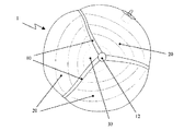
図1は、本発明の第1の態様による内袋1の全体図を示す。内袋1、並びに以下に論じられている別の実施の形態は、ボールの表皮(図示せず)および適用できればカーカス(図1には示されていない)の内部に配置される。しかしながら、内袋の表面に、別個の表皮を必要とせずに内袋1自体をボールとして使用できるように適切なコーティングを設けることも考えられる。 FIG. 1 shows an overall view of an inner bag 1 according to a first aspect of the present invention. The inner bag 1, as well as another embodiment discussed below, is placed inside the ball skin (not shown) and, if applicable, the carcass (not shown in FIG. 1). However, it is also conceivable to provide an appropriate coating on the surface of the inner bag so that the inner bag 1 itself can be used as a ball without the need for a separate skin.
図1の全体図から導かれるように、内袋1の球形体積をいくつかのチャンバ20に分割する補強平面10が内袋の内部に配置されている。概略的にしか示されていない電子デバイス30が、補強平面10の交差部分に配置されており、それによって、内袋1の実質的に中心に配置されている。しかしながら、故障に対する信頼性を増加させるために、内袋の中心の周りに平面上に対称に分布したいくつかの電子デバイス、例えば、いくつかの余分な送信器を配置することも可能である。あるいは、内袋の中心に送信器の重い部品を配置し、軽い部品を内袋内に対称に分布させることも考えられる。例えば、以下に説明する、補強平面10、引張要素60、搭載ケーブル310などの中にアンテナまたは類似の機能要素を分布させてもよい。内袋の外面に一つ以上のアンテナを分布させることも考えられる。
As derived from the overall view of FIG. 1, a reinforcing
内袋1の内部の補強平面10の選択と配置に関して、一方では軽い重量と、他方では電子デバイス30の十分に安定な支持との間で妥協しなければならない。これに関連して、直交する補強平面10はそれほど好ましくないことが分かった。対照的に、6枚の補強平面10全体が組になって約120°の角度で交差している図1から3に示した配置が特に好ましい。その結果、交線11が内袋1の表面に接触する接点12(図1は一つの接点12のみを示し、図2および3では示されていない)が、正四面体の角を画成する。
With regard to the selection and placement of the reinforcing
図4は、多数の補強平面10を有する代わりの実施の形態を示している。補強平面10が内袋1の外面2に接触している接線13(一部だけが示されている)は、膨らませるべきボールの表皮の少なくとも一つのパネルの形状、例えば、よく知られた五角形パネルの形状に実質的に対応しているのが分かる。
FIG. 4 shows an alternative embodiment having multiple reinforcing
図1から4に示した実施の形態において、電子デバイス30が、内袋の中心から外れた場合に、瞬時に元の位置に戻ることを確実にするために、いくつかの機構が用いられる。まず最初に、補強平面10の交差部に配置されていることが好ましいデバイス30がずれると、補強表面10内に歪みが生じ、したがって、能動的な復元力が生じる。さらに、デバイス30が内袋1の中心からずれると、補強平面10および/または内袋1の外面2により画成されるチャンバの体積が変わる。これによって、隣接するチャンバ20内に圧力差が生じ、これがさらに、電子デバイス30を元の位置に迅速に戻らせる。
In the embodiment shown in FIGS. 1-4, several mechanisms are used to ensure that the
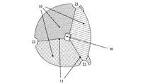
元の位置の周りでの繰り返しの振動を防ぐために、様々なチャンバ20の間に開口部21を設けることが重要なことがある。これによって、圧力を等しくすることができ、開始位置の周りでのデバイス30の振動は、あるチャンバ20から別のチャンバへの気流によって緩和される。これは、オイルが、バンパーのある1つのチャンバから別のチャンバへと小さな開口部を通って流動して、振動動作を緩和させる、自動車における油圧式バンパーの機能に似ている。
It may be important to provide
この内袋1の場合には、この効果は、チャンバ20間の開口部21のサイズにより影響され得る。開口部21の好ましい位置は、(i)内袋の外面にある接線13の交点12、または(ii)図4に示した補強平面10のほぼ中心である。さらに、緩和効果は、内袋1を膨らませるのに使用されるガスの粘度により影響を受け得る。
In the case of the inner bag 1, this effect can be influenced by the size of the
図2と3の比較がさらに別の態様を開示している。図2の実施の形態において、電子デバイス30は、6つの補強平面10の交差部に直接配置されている。図3の実施の形態は、対照的に、4つの追加の補助平面40を有してなり、その内の二つが図3において認識できる。補助平面40は、電子デバイス30が配置されている6つの補強平面10の交差部の周りに別個の体積を形成する。これは、損傷に対して電子デバイス30(図3においては示されていない)を保護するための追加の可能性を与える。
Comparison of FIGS. 2 and 3 discloses yet another embodiment. In the embodiment of FIG. 2, the
非常に鋭いキックのときに、プレーヤーのインステップ・キックがボールと内袋の内部深くまで到達する場合、損傷を防ぐために、例えば、補助平面40により画成される体積に発泡体などを充填することが考えられる。より単純な代替例において、内部体積には、変形を防ぐために特に高圧を有するガスが充填される。この保護機能に加え、補助平面40はさらに、補強平面10により形成される内袋1の内部の骨組みの安定化に寄与する。
If the player's instep kick reaches deep inside the ball and inner bag during a very sharp kick, for example, the volume defined by the
補強平面10、補助平面40および内袋の外面は、熱成形により所望の形状にすることができる、軽量であるが引き裂き抵抗を有する材料から製造されることが好ましい。熱可塑性ウレタン(TPU)から製造された薄いフイルムを使用することが特に好ましい。使用するTPUの厚さ、その材料の性質および適用できる場合には、フイルムの予備膨張などの製造における適切な処理工程が、遠距離範囲に亘る内袋1の動的性質を変えるであろう。ガラス繊維によりTPUフイルムを補強することも考えられる。そのような補強TPUは、例えば、エラストグラム社(Elastogram GmbH)により提供される。
The reinforcing
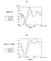
図16aおよび16bは、異なる材料の厚さによる内袋の動的挙動への影響を示している。これらのグラフは、80mph(マイル毎時)(約128km/時)での衝撃の場合の四面体補強平面(図2に示すような)を持つ内袋の動的挙動を示している。図16aは、内袋内部にある送信器に生じた加速(重力加速度gの倍数で)を示し、一方で、図16bは送信器のずれを示している。その中で、送信器は80gの総重量を有するものと仮定した。使用したTPUフイルムの厚さには、内袋の応答挙動に大きな影響があることが直ちに分かる。これは、約1mmの範囲内の壁厚により、比較的低い加速値で最小のたわみに至ることに起因する。約0.5mmの壁厚でもまだ良好な結果が得られるが、約0.15mmの壁厚では、内袋の表皮と持続的に接触することになる。 Figures 16a and 16b show the effect of different material thicknesses on the dynamic behavior of the inner bag. These graphs show the dynamic behavior of an inner bag with a tetrahedral reinforcement plane (as shown in FIG. 2) in the event of an impact at 80 mph (miles per hour) (about 128 km / hour). FIG. 16a shows the acceleration (in multiples of gravitational acceleration g) that occurred in the transmitter inside the inner bag, while FIG. 16b shows the transmitter offset. Among them, the transmitter was assumed to have a total weight of 80 g. It can be immediately seen that the thickness of the TPU film used has a great influence on the response behavior of the inner bag. This is due to wall thicknesses in the range of about 1 mm leading to minimal deflection at relatively low acceleration values. A wall thickness of about 0.5 mm will still give good results, but a wall thickness of about 0.15 mm will provide continuous contact with the skin of the inner bag.
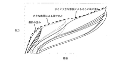
前処理の影響、特に、内袋に使用する前のTPUフイルムの膨張の影響が図17に示されている。このフイルムは、歪み、すなわち、膨張に関する一つのヒステリシス曲線に従わないことが分かる。歪みサイクルのそれぞれのヒステリシス曲線の形状は、代わりに、以前の最大の歪み(第1の膨張に関する濃い実線、第2の膨張に関する点線、および第3の膨張に関する実線を参照のこと)に依存する。次いで、新たなヒステリシス曲線の増加する行き道は、この以前の歪みのヒステリシス曲線の戻り道と実質的に一致する。したがって、内袋におけるTPUフイルムの特定の膨張挙動を達成すべき場合、アセンブリ前にフイルムを、結果として生じるヒステリシス曲線(それゆえ、TPUフイルムの膨張挙動)が所望の形状を示す値まで膨張させることが都合よい。したがって、その結果、内袋におけるTPUフイルムが、ボールを大幅に変形させた後またはボールを大きく加速させた後に弛むことが避けられる。 The effect of pretreatment, in particular the effect of expansion of the TPU film prior to use on the inner bag, is shown in FIG. It can be seen that this film does not follow a single hysteresis curve for strain or expansion. The shape of each hysteresis curve of the strain cycle instead depends on the previous maximum strain (see the dark solid line for the first expansion, the dotted line for the second expansion, and the solid line for the third expansion). . The increasing path of the new hysteresis curve then substantially coincides with the return path of this previous distortion hysteresis curve. Therefore, if a specific expansion behavior of the TPU film in the inner bag is to be achieved, the film is expanded before assembly to a value where the resulting hysteresis curve (and hence the expansion behavior of the TPU film) indicates the desired shape. Is convenient. Therefore, as a result, the TPU film in the inner bag is prevented from sagging after the ball has been greatly deformed or after the ball has been greatly accelerated.
図5に示されている、図1〜4の実施の形態を改変した実施の形態において、補強平面10内に、相当な引張強度を受容でき、かつ、一方の端部で電子デバイス30に、他方の端部で内袋1を囲むボールのカーカス300に、直接的または間接的に取り付けられる一つ以上の搭載ケーブル310が組み込まれている。電子デバイスの吊り下げにカーカス300を伴うと、ボール内部に電子デバイス30を固定する安定性がさらに増す。しかしながら、ケーブル310を内袋1の外面2に接続することだけも可能である。
In a modified version of the embodiment of FIGS. 1-4 shown in FIG. 5, it can receive a significant tensile strength in the reinforcing
図5に示した実施の形態において、搭載ケーブル310は、補強平面10の二つの部分平面の間に位置している。これらの部分平面と搭載ケーブル310との間で相対的な運動が可能であり、例えば、接着、ヒートシールなどによって、搭載ケーブル310を静止した状態にしっかりと固定することも可能である。図5の概念の単純な実施の形態(図示せず)において、部分平面を一つだけ設け、例えば、適切なループまたは対応する孔を通る通路によって、ケーブル310がそこに固定される。この場合、補強平面10との接着も可能である。純粋な搭載機能以外に、送信器30の上述した蓄電器を充電するため、または外部にデータを導くために、電線路を一つ以上のケーブルに組み込んでもよい。どの場合(図5参照)でも、ケーブル310は内袋1を通って外部に貫通するので、送信器30に電力を供給する場合、または送信器との連絡が望ましい場合、追加の通路は必要ない。
In the embodiment shown in FIG. 5, the mounting
図6および7は、本発明のさらに別の態様に関する。これらの実施の形態において、電子デバイスは、内袋1の中心にあるチャンバ50内に配置されている。図3に関して既に説明したように、チャンバ50は、電子デバイス30の追加の保護を与える。しかしながら、チャンバが十分に硬質である材料、例えば、軽量であるが剛性であるプラスチック材料から製造されている場合、チャンバは、本発明による内袋のアセンブリ中に既に電子デバイスの敏感な部品に保護を与える。好ましいプラスチック材料は、熱可塑性ウレタン(TPU)および特に、例えば、TERLURAN(登録商標)の名称で得られるアクリロニトリル・ブタジエン・スチレン(ABS)である。
6 and 7 relate to yet another aspect of the present invention. In these embodiments, the electronic device is disposed in a
図6は、内袋1の中心にチャンバ50、したがって、デバイス30の位置を決定する、いくつかの引張要素60の間にある連結平面51によりチャンバ50が形成されている単純な実施の形態を示している。ある実施の形態において、連結平面51は、好ましくは半径方向に配置された引張要素60の三分の一より多くがチャンバ50内にあるまたはチャンバ50により置き換えられているようなサイズを有する。その結果、電子デバイスを吊り下げるための全体の骨組みが中心で著しく補強される。しかしながら、より小さなチャンバ50となる連結平面51のより小さな実施の形態も考えられる。
FIG. 6 shows a simple embodiment in which the
現在好ましい改良型が図7に示されている。電子デバイス(図示せず)を収容する実質的に球状のチャンバ50が内袋1の中心に配置されている。チャンバ50は、内袋1の内部に関して密封することができる。このことは、チャンバ50が、内袋1の最終製造工程の前に内袋1の内部に配置される場合に特に好ましい。それによって、電子デバイスの敏感な部品への高温または攻撃性ガスの影響が少なくとも減少する。しかしながら、内袋1の内部の高い空気圧によるチャンバ50への機械的負荷を減少させるために、チャンバ50に開口部52(図7参照)を設けることも考えられる。チャンバ50の好ましい球形状が、電子デバイスにさらなる保護を与える。内袋1の中心に到達する衝撃は、平面の側に当たらず、ほとんどの場合、球状チャンバ50を側方に撓めるだけである。これにより、電子デバイス30に有効に作用する加速力が減少する。
A presently preferred refinement is shown in FIG. A substantially
チャンバ50を内袋1の中心に吊り下げるための半径方向の引張要素60は、非常に安定な繊維61の束、例えば、アラミド繊維の束から製造されることが好ましい。従来技術、例えば、独国実用新案第20004174U号明細書とは対照的に、引張要素60は、実質的に弾性がない、または少なくとも高弾性ではないことが好ましい。Technora(登録商標)の商標名で得られるPPTA(ポリパラ−フェニレン−テレフタールアミン)のコポリマーから製造された繊維が特に好ましい。束を形成するために約200よりを平行に配置し、そのような束をいくつか(例えば20から40)よって完全な引張要素60を形成することが好ましい。これらの繊維の特別な利点は、大きな引張強度以外に、250℃までの温度で内袋1をさらに加工することを可能にする高温耐性である。さらに重要な態様は、高い引張強度の場合でさえも、これらの繊維の伸長が非常に小さいことである。引張要素は、初期の長さの最大で30%、好ましくは25%未満、特に好ましくは20%未満しか伸長しない。束そして最終的には引張要素60を構成する一よりは、好ましくは初期の長さの20%未満、特に好ましくは15%未満しか伸長できない。
The
引張要素60の引張強度は1200Nより大きいことが好ましい。これにより、チャンバ50を内袋1の内部に、撓んだときに元の位置への戻りが著しく加速されるように、高張力で吊り下げることができ、これによりボールの位置決めの正確さが改善される。
The tensile strength of the
図19aおよび19bは、二つの異なる衝撃速度、すなわち、60mphおよび80mph(約96km/hおよび約128km/h)での、四面体状に配置された引張要素を有する内袋の応答挙動を示している。高速(点線の曲線)での明らかに高い加速と、外面(パネル)との長い接触とが分かる。 FIGS. 19a and 19b show the response behavior of an inner bag with tensile elements arranged in a tetrahedron at two different impact velocities, namely 60 mph and 80 mph (about 96 km / h and about 128 km / h). Yes. You can see the clearly high acceleration at high speed (dotted curve) and the long contact with the outer surface (panel).
この実施の形態において、引張要素60を適切に設計することによって、内袋の動的性質、すなわち、内袋の変形に対する応答に影響を与えることが一般に可能である。この目的のために、引張要素内の繊維の数、並びに互いとの相互接続を変えてもよい。送信器をしっかりと固定する安定性に選択的に影響を与えるために、非線形膨張挙動を有する上述したアラミド繊維以外の繊維を使用することも考えられる。
In this embodiment, it is generally possible to influence the dynamic properties of the inner bag, i.e. the response to deformation of the inner bag, by appropriately designing the
繊維束61の外端と内端の周りにプラスチック材料を射出して、搭載手段62を製造することが好ましい。この場合、引張要素60は、引張要素を球状チャンバ50にしっかりと固定するために、適切なサイズの開口部53に通して導くことだけが必要である。搭載手段62の周りに射出され、デバイス30の挿入後に互いに挟まれるまたは溶着される二つ以上の(半)殻からチャンバを製造することも考えられる。その結果、内袋の製造は著しく容易になる。
The mounting means 62 is preferably manufactured by injecting a plastic material around the outer and inner ends of the
もう一度射出された搭載手段62を用いて、搭載脚部63を、チャンバ50の反対の引張要素60の端部に配置する。搭載脚部63は、チャンバ50および引張要素60を、内袋1の外面2にしっかりと固定するように働く。これは、接着、高周波溶着またはプラスチック材料に一般的な他の加工技法により行ってもよい。搭載脚部63を十分な耐熱性の材料から製造すれば、内袋1全体は、最終的な成形工程によって所望の形状とサイズにする前に、最初に予備組立てすることもできる。
With the mounting means 62 injected again, the mounting
図13a〜13dは、引張要素60を内袋1の外面2にしっかりと固定するための搭載脚部63の様々な現在好ましい実施の形態を示している。搭載脚部63は、一方で、内袋1の外面2のための十分な大きな接触面65を、他方で、引張強度を保証するためのそれぞれの引張要素60のための支持体を有さなければならない。
FIGS. 13 a-13 d show various currently preferred embodiments of the mounting
図13aの実施の形態において、引張要素(図示せず)は、ピン(図示せず)の周りにループ状に案内され、このピンは、搭載脚部63の接触面65の凹部64内に配置されている。このピンは、十分に安定なプラスチック材料から製造しても、最高の張力に耐えられる金属から製造してもよい。引張要素60(図示せず)の二つのくくりつけていない端部は、この実施の形態においては、チャンバ50に固定される。
In the embodiment of FIG. 13a, a tensioning element (not shown) is guided in a loop around a pin (not shown), which is arranged in a
図13bは、引張要素がその周りを案内される(金属)ピンの代わりに、ボタン状の挿入体67を用いた変更例を示している。この実施の形態は、ボタン状挿入体67は、高い引張応力に耐える大きな表面を有するので、搭載脚部63が完全にプラスチックから製造されている場合により都合よい。
FIG. 13 b shows a modification using a button-
図13cは、製造を単純にすることができるさらに別の変更例を示している。ここでは、引張要素60(図示せず)のループは、さらに別の部品を必要とせずに、接触面65にある適切な凹部68を通して案内される。
FIG. 13c shows yet another variation that can simplify manufacturing. Here, the loop of the tensioning element 60 (not shown) is guided through a
最後に、図13dは、最初に、プラスチック材料が引張要素の端部の周りに射出され、次いで、接触面の凹部により受容される(図13dにおいて詳細に認知できない)実施の形態を示している。この変更例の製造は、特に単純に自動化できる。射出の代わりに、接触面65の凹部により受容される引張要素(図示せず)の外端に結び目を形成することも考えられる。
Finally, FIG. 13d shows an embodiment in which the plastic material is first injected around the end of the tensioning element and then received by a recess in the contact surface (not visible in detail in FIG. 13d). . The production of this variant can be particularly simply automated. As an alternative to injection, it is also conceivable to form a knot at the outer end of a tension element (not shown) received by a recess in the
内袋上の引張要素の搭載脚部63に関して説明した実施例は、より小さな実施の形態において、それぞれの引張要素60の内端でチャンバ50をしっかりと固定するために使用することができる。さらに、一つ以上の引張要素60が内袋1の外面2を通って延在し、カーカス300上にしっかりと固定されている場合に、説明した搭載脚部63を使用しても差し支えない。全ての実施の形態において、引張要素に使用することが好ましい繊維の端部を補強することが意味のあることであろう。
The example described with respect to the tensioning
引張要素60が、対になって実質的に同じ角度で囲むように配置されることが特に好ましい。図7に示すような4つの引張要素の場合、これにより、109.47°の角度で引張要素60の四面体形状が形成される。6つの引張要素を使用する場合、90°の角度となる。
It is particularly preferred that the
送信器の吊り下げのさらに別の安定化について、引張要素60間に一つ以上の横方向の接続手段を配置することも可能である。そのような実施の形態の一つが図14に示されている。中心から半径方向に延在する引張要素60以外に、複数の横方向の接続手段69が見える。三次元の蜘蛛の巣に似た構造が生じる。したがって、ボールの加速中または変形中に生じる力は、内袋全体により均一に分布され、ボールの応答挙動はより均質になる。
It is also possible to arrange one or more lateral connection means between the
図15はさらに別の実施の形態を示している。ここでは、少なくとも一つの引張要素60が、分岐点161から内袋1の外面2へと延在する、複数の副要素160に分岐している。それゆえ、引張要素60を介して伝達される引張負荷の接触点は、外面2の大きな範囲に亘って分布している。図15に示した態様において、分岐点161は外面に近い。しかしながら、分岐点を引張要素60の中心またはチャンバ50の近くに位置させることも可能である。一つ以上の副要素を再度分岐させる構成(図示せず)も考えられる。最後に、図14の横方向の接続手段69を図15の副要素と組み合わせることも可能である(図示せず)。この場合、横方向の接続手段は、引張要素同士、または引張要素と副要素、もしくは副要素同士を接続してもよい。この場合、ボールの力学的性質を確実に均一にするために、少なくとも実質的に対称である構成が好ましい。
FIG. 15 shows still another embodiment. Here, at least one
繊維束、例えば、上述したアラミド繊維を引張要素として使用する場合、分岐点161での分割は、実現するのが特に簡単である。この場合、束は、分岐点161から外面2に異なる方向で延在する、別個の部分束に分割することだけが必要である。
When using fiber bundles, such as the aramid fibers described above, as the tensile element, the division at the branching
図8は、図7の実施の形態の改良形を示している。この実施の形態において、搭載脚部63は、例えば、接着、高周波溶着、または同様の技法によって、カーカス300の内面の対応する搭載面330(図8参照)に接続されている。図5の実施の形態と同様に、カーカス300は、それによって、安定性の程度を追加するために、図8において送信器の吊り下げに含まれる。
FIG. 8 shows an improved version of the embodiment of FIG. In this embodiment, the mounting
図9および10は、本発明のさらに別の態様に関する。この実施の形態において、内袋1、支柱60’およびチャンバ50’は、好ましくは一体の材料片、例えば、ラテックスから製造される。ラテックスは、必要であれば、追加の繊維および/または前処理、例えば、膨張によって補強することができる。この補強繊維は、ラテックス溶液の製造中に加えても、後に導入してもよい。繊維が製造中にラテックス材料中に埋め込まれるように、ラテックス溶液の成形器具の特定の位置に配置することも考えられる。さらに別の実施の形態において、内袋1の弾性特性に局部的に影響を与えるために、厚さの異なるラテックス材料が用いられる。 9 and 10 relate to yet another aspect of the present invention. In this embodiment, the inner bag 1, strut 60 'and chamber 50' are preferably manufactured from a single piece of material, for example latex. The latex can be reinforced by additional fibers and / or pretreatment, such as expansion, if necessary. This reinforcing fiber may be added during the production of the latex solution or may be introduced later. It is also conceivable to place the latex solution at a specific location on the shaping device so that the fibers are embedded in the latex material during manufacture. In yet another embodiment, latex materials of different thicknesses are used to locally affect the elastic properties of the inner bag 1.
内袋1は、内袋1の外面から内部に延在し、チャンバ50’を画成する複数の中空支柱60’を有してなる。中空支柱60’の一つは、電子デバイス30を挿入し、必要であれば取り出すための大きな直径を有する。この中空支柱の重い重量を埋め合わせるために、反対側に内袋1の弁のための受容部70を配置することが好ましい。その結果、膨らまされた内袋が不釣り合いとなることは大部分避けられる。内袋1が膨らまされたときに、空気圧がチャンバ50’の壁51’をデバイス30に押し付け、どのような追加の手法も必要とせずに、デバイス30を内袋1の中心に固定する。上述した実施の形態とは対照的に、電子デバイスを挿入した後には、もはや接着も溶着も必要ない。図9のチャンバ50’並びに中空支柱60’の形状と直径は単に概要である。複数の電子デバイス、例えば、上述した余分な送信器を受容するために、他の寸法並びにいくつかのチャンバ50’の配置も考えられる。
The inner bag 1 has a plurality of
図10は、図9の実施の形態の改良例を示しており、ここでは、送信器30は、中空支柱60’を通って延在する追加の搭載ケーブル310によってカーカス300に固定されている。この実施の形態は、ケーブル310が、送信器30を内袋1の中心に安定な様式で維持するのに十分な張力を生じさせることができるので、どのような補強ラテックス材料も必要とせずに実施できる。したがって、図10の実施の形態は、都合のよい様式で、図7および8の実施の形態の態様を、図9の改良例と組み合わせている。
FIG. 10 shows an improvement of the embodiment of FIG. 9, where the
加速と撓みへの異なるラテックス材料の影響が図18aおよび18bに示されている。特に、それぞれの使用する材料によって、最初の衝撃後の振動挙動が明らかに異なることが分かる。点線の曲線は、約357ms後の送信器の著しい第2の加速を示すが、この「後振動」は、実線の曲線に対応する材料には全く観察できない。「2×C10ラテックス」と称する材料は、「ベースラテックス」と称する材料と比較して実質的に二倍の硬さを有する。 The effect of different latex materials on acceleration and deflection is shown in FIGS. 18a and 18b. In particular, it can be seen that the vibration behavior after the first impact is clearly different depending on the materials used. The dotted curve shows a significant second acceleration of the transmitter after about 357 ms, but this “post vibration” is not observable at all in the material corresponding to the solid curve. The material referred to as “2 × C10 latex” has substantially twice the hardness compared to the material referred to as “base latex”.
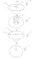
図11および12は、複雑な内袋、例えば、図1〜4に示した内袋1を製造するための考えられる装置を示している。この目的のために、いくつかの成形部材100が、融点の低い材料、例えば、ワックス、または適切な液体(水または油など)中に溶解する材料から製造される。ここに開示される実施の形態において、成形部材100は、球のセグメントとして形成される。ピン状の接続体101を用いて、これらの成形部材100は、水平と垂直の間隙102が球を通って延在するように組み立てられる。幾何学的な観点から、間隙102は、球の中心にその中心を持つデカルト座標系により定義される平面にある。特に、図2に示した補強要素の四面体構成を形成するための、他の構成も可能である。
FIGS. 11 and 12 show a possible device for producing a complex inner bag, for example the inner bag 1 shown in FIGS. For this purpose, several molded
組み立てた部材100を、成形、例えば、射出成形または適切な内袋材料(例えば、ラテックス)の溶液中への浸漬のために使用すれば、内部に補強平面を有する一体の内袋が形成される。最後の成形工程の最中に、送信器(図示せず)を、成形部材100によりその位置に維持しても、完成した内袋中に後で挿入してもよい。ピン状の接続体101のために、成形部材100の周りに成形された内袋のセグメントの間に管状の接続部がある。その結果、内袋1全体を膨らませるために、一つの弁接続(図示せず)しか必要ない。
If the assembled
図12は、所望の位置に内袋1を成形する最中に成形部材100を維持するための装置を示している。この目的のために、金属片またはプラスチック片201などから製造された外部の骨組み200を、いくつかの方向から、組み立てられた成形体の内部を通って延在するワイヤ202と共に用いる。さらに、ワイヤ202は、内袋を製造する最中に送信器を適所に保持するように働いてもよい。最後に、ワイヤ202は、送信器を上述した様式でカーカスにしっかりと固定する搭載ケーブル310として後に働くことができるように、製造中に内袋中に組み込んでもよい。
FIG. 12 shows an apparatus for maintaining the molded
成形プロセスを終了したときに、外部の骨組み200を取り外し、成形部材100を含む内袋を、使用した材料の融点まで加熱する。次いで、内袋を動かすことにより、弁の開口部を通して液体材料を除去する(弁を挿入する前に)。液体中に溶解する成形部品の場合、これらの部品は、適切な溶剤に接触させることにより溶解される。その結果、複雑な内袋形状は、内袋の中心に電子デバイスをしっかりと固定するための手作業の工程を大部分はもはや必要としない上述した方法によって製造できる。
When the molding process is finished, the
1 内袋
10 補強平面
20 チャンバ
30 電子デバイス
40 補助平面
1
Claims (32)
a. 前記内袋の内部に延在する少なくとも二つの補強平面(10)、および
b. 前記内袋(1)内に配置され、前記補強平面(10)によって所定の位置に維持される少なくとも一つの電子デバイス(30)を有し、
前記電子デバイス(30)が前記少なくとも二つの補強平面(10)の間の交線(11)に配置されていることを特徴とする内袋(1)。 An inner bag (1) for a ball to be inflated,
a. At least two reinforcing planes (10) extending into the inner bag; and b. Having at least one electronic device (30 ) disposed in the inner bag (1) and maintained in place by the reinforcing plane (10) ;
Inner bag (1) , characterized in that the electronic device (30) is arranged at a line of intersection (11) between the at least two reinforcing planes (10 ).
a. 前記内袋(1)内の別個のチャンバ(50)の内部に配置された少なくとも一つの電子デバイス(30)、および
b. 前記電子デバイス(30)を前記内袋(1)内の所定の位置に維持するように配置された複数の実質的に弾性のない引張要素(60)、
を有してなる内袋(1)。 An inner bag (1) for a ball to be inflated,
a. At least one electronic device (30) disposed within a separate chamber (50 ) within the inner bag (1); and b. A plurality of substantially inelastic tension elements (60) arranged to maintain the electronic device (30) in place within the inner bag (1);
An inner bag (1).
a. 前記内袋(1)が膨らまされたときに該内袋(1)の外側から内側に半径方向に延在し、該内袋(1)の実質的に中心にチャンバ(50’)を画成する複数の中空支柱(60’)、および
b. 前記チャンバ(50’)の内部に配置された少なくとも一つの電子デバイス(30)、
を有してなり、前記中空支柱(60’)の少なくとも一つが、前記デバイス(30)を、該中空支柱(60’)を通して、前記内袋(1)の外側から内側に挿入できるように他の中空支柱(60’)とは異なる十分なサイズを有することを特徴とする内袋(1)。 An inner bag (1) for a ball to be inflated,
a. When the inner bag (1) is inflated, it extends radially from the outside to the inside of the inner bag (1) and defines a chamber (50 ') substantially at the center of the inner bag (1). A plurality of hollow struts (60 '), and b. At least one electronic device (30) disposed within the chamber (50 ′);
Becomes a, the hollow struts (60 ') at least one of the said device (30), the hollow struts (60' other for insertion through), from the outside to the inside of the inner bag (1) An inner bag (1) characterized in that it has a sufficient size different from the hollow strut (60 ' ).
Applications Claiming Priority (1)
| Application Number | Priority Date | Filing Date | Title |
|---|---|---|---|
| DE102004045176A DE102004045176B4 (en) | 2004-09-17 | 2004-09-17 | bladder |
Publications (3)
| Publication Number | Publication Date |
|---|---|
| JP2006081912A JP2006081912A (en) | 2006-03-30 |
| JP2006081912A5 JP2006081912A5 (en) | 2006-06-22 |
| JP4448077B2 true JP4448077B2 (en) | 2010-04-07 |
Family
ID=35229817
Family Applications (1)
| Application Number | Title | Priority Date | Filing Date |
|---|---|---|---|
| JP2005271561A Active JP4448077B2 (en) | 2004-09-17 | 2005-09-20 | Bowl inner bag and bowl |
Country Status (6)
| Country | Link |
|---|---|
| US (2) | US7740551B2 (en) |
| EP (3) | EP2281610B1 (en) |
| JP (1) | JP4448077B2 (en) |
| CN (3) | CN101601914B (en) |
| AT (2) | ATE411089T1 (en) |
| DE (3) | DE102004045176B4 (en) |
Families Citing this family (132)
| Publication number | Priority date | Publication date | Assignee | Title |
|---|---|---|---|---|
| IT1331953B1 (en) * | 2002-09-17 | 2006-01-30 | Serena Capriotti | Inner tube with electronic sensors inside that detect the passage of the ball on the goal line even if covered by players |
| US20080227696A1 (en) * | 2005-02-22 | 2008-09-18 | Biosurface Engineering Technologies, Inc. | Single branch heparin-binding growth factor analogs |
| US7611429B2 (en) * | 2005-03-01 | 2009-11-03 | Primo Research, Inc. | Inflatable articles that provide long term inflation and pressure control |
| US7520830B2 (en) * | 2005-08-11 | 2009-04-21 | Wong Jacob Y | Game ball |
| BRPI0602923A (en) * | 2006-06-28 | 2008-02-12 | Roberto Estefano | intra ball connection module |
| US20080242458A1 (en) * | 2007-04-02 | 2008-10-02 | Winn Travis J | Street Soccer Ball |
| JP5142366B2 (en) * | 2007-10-31 | 2013-02-13 | 学校法人東京電機大学 | Play ball |
| EP2260453A4 (en) * | 2008-02-14 | 2016-03-23 | Infomotion Sports Technologies Inc | Electronic analysis of athletic performance |
| US8182379B2 (en) | 2008-06-27 | 2012-05-22 | Nike, Inc. | Sport balls and methods of manufacturing the sport balls |
| US8192311B2 (en) * | 2008-06-27 | 2012-06-05 | Nike, Inc. | Sport ball with a textile restriction structure |
| US8210973B2 (en) * | 2008-06-27 | 2012-07-03 | Nike, Inc. | Sport ball bladder |
| US8708847B2 (en) | 2008-06-27 | 2014-04-29 | Nike, Inc. | Sport ball casing and methods of manufacturing the casing |
| US8852039B2 (en) | 2011-06-28 | 2014-10-07 | Nike, Inc. | Sport ball casing with integrated bladder material |
| AU2009289404B2 (en) | 2008-09-05 | 2013-01-10 | Warrior Sports, Inc. | Inflatable latex neoprene bladders |
| TW201010760A (en) * | 2008-09-15 | 2010-03-16 | geng-xian Lin | Light-emitting ball |
| FR2936140B1 (en) * | 2008-09-22 | 2013-01-18 | Univ Troyes Technologie | DEVICE FOR EVALUATING AND / OR STRENGTHENING THE FORCE OF GRIPPING |
| DE102008058821B4 (en) * | 2008-11-25 | 2016-01-21 | Adidas International Marketing B.V. | Ball valve and method of making a ball valve |
| DE102008058943B3 (en) | 2008-11-25 | 2010-05-12 | Adidas International Marketing B.V. | Bubble for a ball |
| US8293051B2 (en) * | 2008-12-10 | 2012-10-23 | The Boeing Company | Method for producing composite laminates using a collapsible mandrel |
| US9296187B2 (en) | 2008-12-10 | 2016-03-29 | The Boeing Company | Bagging process and mandrel for fabrication of elongated composite structure |
| US8029394B2 (en) * | 2009-03-04 | 2011-10-04 | Tachikara Usa, Inc. | Game ball with noise suppression disk |
| US8608599B2 (en) | 2009-03-20 | 2013-12-17 | Nike, Inc. | Sport ball casing and methods of manufacturing the casing |
| US8974330B2 (en) | 2009-03-20 | 2015-03-10 | Nike, Inc. | Sport ball casing and methods of manufacturing the casing |
| CN102481478B (en) | 2009-03-27 | 2015-06-03 | 英福摩迅运动科技公司 | Monitoring of physical training events |
| US10821329B2 (en) | 2009-11-19 | 2020-11-03 | Wilson Sporting Goods Co. | Football sensing |
| US10668333B2 (en) | 2009-11-19 | 2020-06-02 | Wilson Sporting Goods Co. | Football sensing |
| US10751579B2 (en) | 2009-11-19 | 2020-08-25 | Wilson Sporting Goods Co. | Football sensing |
| US8512177B2 (en) | 2009-11-19 | 2013-08-20 | Wilson Sporting Goods Co. | American-style football including improved bladder construction for mounting of electronics |
| US9636550B2 (en) | 2009-11-19 | 2017-05-02 | Wilson Sporting Goods Co. | Football sensing |
| US8579743B2 (en) * | 2010-01-05 | 2013-11-12 | Nike, Inc. | Sport balls and methods of manufacturing the sport balls |
| EP2353666A1 (en) * | 2010-02-08 | 2011-08-10 | Cairos technologies AG | Ball bladder holding a device |
| US20110218065A1 (en) * | 2010-03-04 | 2011-09-08 | Cavallaro Richard H | Ball |
| US8517870B2 (en) * | 2010-09-07 | 2013-08-27 | Infomotion Sports Technologies, Inc. | Electronic component enclosure for an inflated object |
| US9370693B2 (en) | 2010-12-03 | 2016-06-21 | Nike, Inc. | Sport ball with indented casing |
| US8617011B2 (en) | 2010-12-03 | 2013-12-31 | Nike, Inc. | Sport ball with indented casing |
| US10363453B2 (en) | 2011-02-07 | 2019-07-30 | New Balance Athletics, Inc. | Systems and methods for monitoring athletic and physiological performance |
| CN103442607B (en) | 2011-02-07 | 2016-06-22 | 新平衡运动公司 | For monitoring the system and method for athletic performance |
| US20120244969A1 (en) | 2011-03-25 | 2012-09-27 | May Patents Ltd. | System and Method for a Motion Sensing Device |
| US8730037B2 (en) | 2011-03-28 | 2014-05-20 | Physical Apps, Llc | Physical interaction device for personal electronics and method for use |
| US8672784B2 (en) | 2011-05-04 | 2014-03-18 | Nike, Inc. | Sport ball with an inflation-retention bladder |
| US8771115B2 (en) | 2011-05-04 | 2014-07-08 | Nike, Inc. | Sport ball with an inflation-retention bladder |
| US8597144B2 (en) | 2011-06-28 | 2013-12-03 | Nike, Inc. | Sport ball casing with thermoplastic reinforcing material |
| US9327608B2 (en) | 2011-08-04 | 2016-05-03 | Schneider Electric USA, Inc. | Extendable and deformable carrier for a primary coil of a charging system |
| US20130167290A1 (en) * | 2011-12-30 | 2013-07-04 | Ariel BEN EZRA | Sensor activated ball and sport accessory with computer functionalities |
| US9339691B2 (en) | 2012-01-05 | 2016-05-17 | Icon Health & Fitness, Inc. | System and method for controlling an exercise device |
| JP5005119B1 (en) * | 2012-01-10 | 2012-08-22 | 真司 葛山 | Transparent ball for ball games |
| US8926459B2 (en) | 2012-03-30 | 2015-01-06 | Nike, Inc. | Sport balls and methods of manufacturing the sport balls |
| US9257054B2 (en) | 2012-04-13 | 2016-02-09 | Adidas Ag | Sport ball athletic activity monitoring methods and systems |
| US10076685B2 (en) | 2012-07-02 | 2018-09-18 | Russell Brands, Llc | Operations with instrumented game ball |
| US10616663B2 (en) | 2012-07-02 | 2020-04-07 | Russell Brands, Llc | Computer-implemented capture of live sporting event data |
| US9586099B2 (en) | 2012-07-09 | 2017-03-07 | Catapult Group International Pty Ltd | Tracking balls in sports |
| US9901801B2 (en) | 2012-11-09 | 2018-02-27 | Wilson Sporting Goods Co. | Basketball sensing apparatus |
| US10449421B2 (en) * | 2012-11-09 | 2019-10-22 | Wilson Sporting Goods Co. | Basketball electronics support |
| US9844704B2 (en) | 2012-11-09 | 2017-12-19 | Wilson Sporting Goods Co. | Basketball sensing apparatus |
| US10252118B2 (en) * | 2012-11-09 | 2019-04-09 | Wilson Sporting Goods Co. | Basketball with electronics |
| US9623311B2 (en) | 2012-11-09 | 2017-04-18 | Wilson Sporting Goods Co. | Basketball sensing apparatus |
| US9656140B2 (en) | 2012-11-09 | 2017-05-23 | Wilson Sporting Goods Co. | Sport performance system with ball sensing |
| US9283457B2 (en) | 2012-11-09 | 2016-03-15 | Wilson Sporting Goods Co. | Sport performance system with ball sensing |
| US10022593B2 (en) * | 2012-11-09 | 2018-07-17 | Wilson Sporting Goods Co. | Basketball having a reduced moment of inertia |
| US10159884B2 (en) | 2012-11-09 | 2018-12-25 | Wilson Sporting Goods Co. | Basketball make-miss shot sensing |
| US9656142B2 (en) | 2012-11-09 | 2017-05-23 | Wilson Sporting Goods Co. | Basketball shot determination system |
| US9724570B2 (en) | 2012-11-09 | 2017-08-08 | Wilson Sporting Goods Co. | Ball lighting |
| US9656143B2 (en) | 2012-11-09 | 2017-05-23 | Wilson Sporting Goods Co. | Basketball shot determination system |
| US9610746B2 (en) | 2013-02-13 | 2017-04-04 | Adidas Ag | Methods for manufacturing cushioning elements for sports apparel |
| DE102013202485B4 (en) | 2013-02-15 | 2022-12-29 | Adidas Ag | Ball for a ball sport |
| CN103083875B (en) * | 2013-02-20 | 2014-10-15 | 黑龙江八一农垦大学 | Football |
| US9500464B2 (en) | 2013-03-12 | 2016-11-22 | Adidas Ag | Methods of determining performance information for individuals and sports objects |
| WO2014153158A1 (en) | 2013-03-14 | 2014-09-25 | Icon Health & Fitness, Inc. | Strength training apparatus with flywheel and related methods |
| US20140274504A1 (en) * | 2013-03-14 | 2014-09-18 | Russell Brands, Llc | Inflation-Independent Ball with Cover |
| US9308426B2 (en) | 2013-03-15 | 2016-04-12 | Wilson Sporting Goods Co. | Ball sensing |
| USD776410S1 (en) | 2013-04-12 | 2017-01-17 | Adidas Ag | Shoe |
| US9616279B2 (en) * | 2013-05-13 | 2017-04-11 | Coulter Ventures Llc | Exercise device |
| US10285899B2 (en) * | 2013-05-13 | 2019-05-14 | Coulter Ventures Llc | Exercise device |
| US9833650B2 (en) * | 2013-05-14 | 2017-12-05 | Coulter Ventures Llc | Exercise device |
| US20140357333A1 (en) * | 2013-06-02 | 2014-12-04 | Dan Kevin Canobbio | Gaming apparatus for producing audio-visual signals |
| FR3010909B1 (en) * | 2013-09-25 | 2015-09-18 | Commissariat Energie Atomique | DEVICE FOR ACTING ON SHOCKS AND COMPRISING INTERNAL PIEZOELECTRIC MEANS FOR ENERGY RECOVERY |
| WO2015100429A1 (en) | 2013-12-26 | 2015-07-02 | Icon Health & Fitness, Inc. | Magnetic resistance mechanism in a cable machine |
| AU2015223149A1 (en) | 2014-02-28 | 2016-09-22 | Russell Brands, Llc | Data processing inside gaming device |
| WO2015138339A1 (en) | 2014-03-10 | 2015-09-17 | Icon Health & Fitness, Inc. | Pressure sensor to quantify work |
| US9849361B2 (en) | 2014-05-14 | 2017-12-26 | Adidas Ag | Sports ball athletic activity monitoring methods and systems |
| US10523053B2 (en) | 2014-05-23 | 2019-12-31 | Adidas Ag | Sport ball inductive charging methods and systems |
| WO2015191445A1 (en) | 2014-06-09 | 2015-12-17 | Icon Health & Fitness, Inc. | Cable system incorporated into a treadmill |
| WO2015195965A1 (en) | 2014-06-20 | 2015-12-23 | Icon Health & Fitness, Inc. | Post workout massage device |
| US9289657B1 (en) * | 2014-06-24 | 2016-03-22 | Chris Rice | Football with free moving weight |
| US9916001B2 (en) | 2014-07-08 | 2018-03-13 | Wilson Sporting Goods Co. | Sport equipment input mode control |
| CN104117184B (en) * | 2014-08-11 | 2017-04-12 | 东莞博登运动用品有限公司 | Exercise ball liner |
| CN104147764A (en) * | 2014-09-03 | 2014-11-19 | 洪满 | Air resistance ball |
| US10238941B2 (en) | 2014-10-07 | 2019-03-26 | ShotTracker, Inc. | Basketball net which detects shots that have been made successfully |
| US20160238099A1 (en) * | 2015-02-12 | 2016-08-18 | Scott Victor Perino | Advanced Omnidirectional Impact Absorber |
| US10391361B2 (en) | 2015-02-27 | 2019-08-27 | Icon Health & Fitness, Inc. | Simulating real-world terrain on an exercise device |
| EP3090784A1 (en) * | 2015-04-08 | 2016-11-09 | Amer Sport Italia SpA | Fitness training aid |
| CN106178437A (en) * | 2015-05-04 | 2016-12-07 | 顽石运动智能科技(北京)有限公司 | A kind of novel bladders |
| CN106267744A (en) * | 2015-05-11 | 2017-01-04 | 顽石运动智能科技(北京)有限公司 | A kind of novel bladders |
| DE102015209795B4 (en) * | 2015-05-28 | 2024-03-21 | Adidas Ag | Ball and process for its production |
| DE102015209811B3 (en) | 2015-05-28 | 2016-12-01 | Adidas Ag | Non-inflatable sports balls |
| CN105056493B (en) * | 2015-07-14 | 2017-03-15 | 南京绎霖国际贸易有限公司 | There is bladders of sandwich structure and preparation method thereof |
| USD783264S1 (en) | 2015-09-15 | 2017-04-11 | Adidas Ag | Shoe |
| BR112018009299B1 (en) | 2015-11-10 | 2022-06-28 | Ddsports, Inc | METHOD FOR DETERMINING WHETHER A PLAYER HAS SCORED A POINT, AND, SYSTEM FOR TRACKING PLAYERS AND A GAMEPLAY OBJECT. |
| DE102015223885B4 (en) | 2015-12-01 | 2024-03-21 | Adidas Ag | ball |
| DE202015008658U1 (en) | 2015-12-21 | 2017-03-22 | Socca360 GmbH | ball |
| TWM520923U (en) * | 2016-01-30 | 2016-05-01 | 和碩聯合科技股份有限公司 | Ball |
| US10272317B2 (en) | 2016-03-18 | 2019-04-30 | Icon Health & Fitness, Inc. | Lighted pace feature in a treadmill |
| US10493349B2 (en) | 2016-03-18 | 2019-12-03 | Icon Health & Fitness, Inc. | Display on exercise device |
| US10625137B2 (en) | 2016-03-18 | 2020-04-21 | Icon Health & Fitness, Inc. | Coordinated displays in an exercise device |
| US10034519B2 (en) | 2016-06-16 | 2018-07-31 | Adidas Ag | UV curable lattice microstructure for footwear |
| USD840137S1 (en) | 2016-08-03 | 2019-02-12 | Adidas Ag | Shoe midsole |
| USD840136S1 (en) | 2016-08-03 | 2019-02-12 | Adidas Ag | Shoe midsole |
| USD852475S1 (en) | 2016-08-17 | 2019-07-02 | Adidas Ag | Shoe |
| JP1582717S (en) | 2016-09-02 | 2017-07-31 | ||
| CN106310615A (en) * | 2016-09-21 | 2017-01-11 | 武汉汇动乐智科技有限公司 | Electronic football body |
| CN106606844B (en) * | 2016-09-27 | 2019-08-20 | 简极科技有限公司 | A kind of more air bag intelligent spheres and its production technology |
| CN106606845A (en) * | 2016-09-27 | 2017-05-03 | 简极科技有限公司 | A double-air bag intelligent ball and a production process therefor |
| US10671705B2 (en) | 2016-09-28 | 2020-06-02 | Icon Health & Fitness, Inc. | Customizing recipe recommendations |
| US9993694B1 (en) * | 2016-12-12 | 2018-06-12 | William J. Warren | Recreational device with rotor assembly |
| CN106422220B (en) * | 2016-12-27 | 2018-10-23 | 赵红军 | A kind of basketball that weight-adjustable contour structures are stablized |
| CN106730666A (en) * | 2017-02-07 | 2017-05-31 | 广东荣承体育用品制造有限公司 | Inner-tube structure of Intelligent football and preparation method thereof |
| US10675526B2 (en) | 2017-05-01 | 2020-06-09 | Intel Corporation | Sports apparatus and methods including tracking additives |
| US10029155B1 (en) * | 2017-07-07 | 2018-07-24 | Chien-Chuan LO | Inflatable sports ball having an inner bladder with rib plates |
| USD899061S1 (en) | 2017-10-05 | 2020-10-20 | Adidas Ag | Shoe |
| US10183199B1 (en) | 2017-10-15 | 2019-01-22 | William J. Warren | Tubular projectile device |
| EP3287175A1 (en) * | 2017-11-14 | 2018-02-28 | Basu Swati | An inflatable ball bladder with two dual function valves and a wired rechargeable electronic component |
| USD839367S1 (en) | 2017-11-23 | 2019-01-29 | William J Warren | Ball for recreational use |
| EP4156458A1 (en) | 2018-03-27 | 2023-03-29 | DDSports, Inc. | Wireless charging pod and charging pod rack for game devices with rechargeable batteries |
| EP3557559A1 (en) | 2018-04-20 | 2019-10-23 | TMRW Foundation IP & Holding S.A.R.L. | Sports events broadcasting systems and methods |
| WO2020257227A1 (en) | 2019-06-17 | 2020-12-24 | Ddsports, Inc. | Sports ball with electronics housed in shock-absorbing carrier |
| JP2021045292A (en) * | 2019-09-17 | 2021-03-25 | 中松 義郎 | Information ball |
| TWM590470U (en) * | 2019-09-23 | 2020-02-11 | 林宜靜 | Sensor positioning structure |
| CN111872015B (en) * | 2020-06-01 | 2021-06-01 | 许昌学院 | Magnetic pulse mineralized refuse treatment device |
| CN111617451A (en) * | 2020-06-09 | 2020-09-04 | 武汉体育学院 | Intelligent spherical inner container |
| WO2022053741A1 (en) | 2020-09-09 | 2022-03-17 | Wisehockey Oy | A ball and a method for manufacturing the same |
| CN112370749A (en) * | 2020-10-28 | 2021-02-19 | 南京群力运动器材有限公司 | Wave basketball manufacturing process and wave basketball |
| US20240001203A1 (en) * | 2022-07-01 | 2024-01-04 | Adidas Ag | Sports ball with suspension system |
Family Cites Families (270)
| Publication number | Priority date | Publication date | Assignee | Title |
|---|---|---|---|---|
| US415884A (en) * | 1889-11-26 | shibe | ||
| US495863A (en) * | 1893-04-18 | whitz | ||
| FR1488920A (en) | 1967-10-26 | |||
| US360917A (en) * | 1887-04-12 | John book | ||
| US830582A (en) * | 1905-12-28 | 1906-09-11 | Charles R Fleischman | Inflated ball. |
| US996458A (en) * | 1910-10-24 | 1911-06-27 | Ava R Coleman | Game apparatus. |
| US1187029A (en) * | 1916-02-07 | 1916-06-13 | James L Beebout | Basket-ball and similar playing-ball. |
| US1614853A (en) * | 1923-06-05 | 1927-01-18 | Schwartz Louis | Ball |
| US1597823A (en) | 1925-04-04 | 1926-08-31 | Randolph Simon | Light-projecting attachment for shoes |
| US1923236A (en) * | 1929-04-30 | 1933-08-22 | P Goldsmith Sons Company | Game ball |
| US2078881A (en) * | 1933-03-20 | 1937-04-27 | Rohm & Haas | Process for coating rubber and product |
| US2020484A (en) * | 1933-06-15 | 1935-11-12 | Clinton T Turner | Luminous ball |
| US2221534A (en) * | 1937-11-06 | 1940-11-12 | Voit | Method of making athletic balls |
| US2653818A (en) * | 1949-01-22 | 1953-09-29 | Voit Rubber Corp | Fabric reinforced football |
| US2653817A (en) * | 1949-07-25 | 1953-09-29 | Voit Rubber Corp | Ball tethering device |
| DE829109C (en) * | 1950-11-11 | 1952-01-21 | Friedrich Bartels | Air-filled, thin-walled game ball |
| DE1013126B (en) | 1954-07-10 | 1957-08-01 | Continental Gummi Werke Ag | Elastic bearing for machines and devices |
| US2760278A (en) | 1955-03-31 | 1956-08-28 | Agrillo Paul | Outsole for ultimate balance and shoe comfort |
| US2897609A (en) | 1956-03-19 | 1959-08-04 | Lawrence E Bodkin | Storage shoe heel |
| US2874964A (en) * | 1957-07-09 | 1959-02-24 | Bayshore Ind Inc | Decorative hollow play balls |
| US3119618A (en) * | 1959-05-27 | 1964-01-28 | Spalding A G & Bros Inc | Inflated game ball |
| DE1172585B (en) * | 1960-09-02 | 1964-06-18 | Licentia Gmbh | Playball that emits sound in all phases of movement, especially playballs for blind sports |
| US3112521A (en) * | 1961-03-08 | 1963-12-03 | Louis F Muccino | Apparatus for covering golf balls |
| GB933053A (en) | 1961-04-22 | 1963-07-31 | Ignacio Lacruz Abio | Improvements in or relating to balls |
| US3185476A (en) * | 1962-08-30 | 1965-05-25 | Walter W Fechner | Spherical ball including an internal resilient hand grip |
| US3229976A (en) * | 1963-03-25 | 1966-01-18 | Jr Walter L Allen | Illuminated beach balls |
| US3508750A (en) * | 1964-09-11 | 1970-04-28 | Voit Rubber Corp | Game ball |
| US3616165A (en) * | 1966-05-04 | 1971-10-26 | Tetsuo Nishi | Super-strong cord and tape composed of polyvinyl alcohol fibers |
| US3580575A (en) * | 1967-08-28 | 1971-05-25 | Autotelic Ind Ltd | Game device including selectively impact operable lights |
| DE2125758A1 (en) | 1971-05-25 | 1972-12-07 | Stübbe Maschinenfabrik GmbH, 4925 Kalletal-Kalldorf | Polyurethane foam sports ball - with the appearance dimensions weight and properties of a leather ball |
| FR2215249A1 (en) | 1973-01-25 | 1974-08-23 | Audry Julien | Sports ball with expanded PVC cover - has sewn panels of coated inextensible fabric composite |
| US4065150A (en) * | 1976-01-26 | 1977-12-27 | Exxon Research And Engineering Company | Ski and method of making same |
| FR2352649A1 (en) * | 1976-05-25 | 1977-12-23 | Delacoste & Cie | PLASTIC BALL AND ROTATION MOLDING MANUFACTURING PROCESS |
| BG43028A3 (en) * | 1977-04-13 | 1988-04-15 | Gala Np,Cs | Inflatable sport ball and method for its manufacture |
| CA1104601A (en) * | 1977-05-03 | 1981-07-07 | Peter C. Western | Ball attachment |
| JPS5465638A (en) | 1977-11-02 | 1979-05-26 | Bridgestone Corp | Golf ball with high surface strength |
| US4175446A (en) | 1978-04-26 | 1979-11-27 | The University Of Iowa Research Foundation | Step counting device and method |
| DE2827810C2 (en) * | 1978-06-24 | 1983-03-17 | Zahnradfabrik Friedrichshafen Ag, 7990 Friedrichshafen | Automotive control for a hydrostatic drive |
| FR2443850A1 (en) | 1978-12-15 | 1980-07-11 | Piraud Robert | Use of foam-lined moulds and covers for panelled inflatable balls mfr. - to simulate hand stitched panelled balls using prodn. line techniques |
| US4333648A (en) * | 1979-02-06 | 1982-06-08 | Molten Rubber Industry Co., Ltd. | Inflatable game ball |
| US4261565A (en) | 1980-02-19 | 1981-04-14 | Ideas That Sell, Inc. | Ball and method of making same |
| US4399992A (en) * | 1980-03-10 | 1983-08-23 | Questor Corporation | Structural member having a high strength to weight ratio and method of making same |
| US4285846A (en) * | 1980-04-28 | 1981-08-25 | Cabot Corporation | Flatted water-reducible coating compositions and method for producing same |
| US4318544A (en) * | 1980-10-30 | 1982-03-09 | W. H. Brine Company | Game ball |
| JPS5784068A (en) * | 1980-11-15 | 1982-05-26 | Yunikon Kk | Ball with ball speedometer |
| US4402147A (en) | 1981-05-27 | 1983-09-06 | Chyuan Jong Wu | Shoe having automatic step counter |
| JPS58215335A (en) | 1982-06-10 | 1983-12-14 | Multi Giken Kk | Manufacture of ball |
| US4462590A (en) * | 1982-10-22 | 1984-07-31 | Figgie International Inc. | Inflatable padded game ball |
| DE3405081A1 (en) | 1984-02-13 | 1985-08-14 | Puma-Sportschuhfabriken Rudolf Dassler Kg, 8522 Herzogenaurach | SPORTSHOE FOR RUNNING DISCIPLINES AND METHOD FOR SUBMITTING INFORMATION AND / OR FOR EXCHANGING INFORMATION ON MOTION PROCESSES IN RUNNING DISCIPLINES |
| US4649552A (en) | 1984-03-19 | 1987-03-10 | Matsushita Electric Works, Ltd. | Electronic pedometer with step sensor in removable insole |
| JPS60200120A (en) | 1984-03-24 | 1985-10-09 | Matsushita Electric Works Ltd | Pedometer |
| DE3447171A1 (en) | 1984-03-19 | 1985-09-19 | Matsushita Electric Works, Ltd., Kadoma, Osaka | Electronic step counter |
| US4802671A (en) * | 1984-07-05 | 1989-02-07 | Gentiluomo Joseph A | Bowling ball |
| DE3506055A1 (en) | 1985-02-21 | 1986-08-21 | Sachs Systemtechnik Gmbh, 8720 Schweinfurt | Elastic sole for a shoe |
| FR2572674A1 (en) | 1985-04-26 | 1986-05-09 | Tassin Charles | Process for manufacturing hollow bodies by low-pressure injection around a prefabricated bladder |
| US4660831A (en) * | 1985-09-16 | 1987-04-28 | Figgie International Inc. | Inflatable padded game ball |
| DE3536803A1 (en) * | 1985-10-16 | 1987-04-16 | Peter Walker | WALKER - TRAINER |
| US4856781A (en) * | 1986-01-16 | 1989-08-15 | Molten Corporation | Game ball |
| US4771394A (en) | 1986-02-03 | 1988-09-13 | Puma Aktiengesellschaft Rudolf Dassler Sport | Computer shoe system and shoe for use therewith |
| US4814661A (en) | 1986-05-23 | 1989-03-21 | Washington State University Research Foundation, Inc. | Systems for measurement and analysis of forces exerted during human locomotion |
| DE3643236A1 (en) | 1986-12-18 | 1988-07-07 | Ruhrkohle Ag | PERSONAL PROTECTION RADIO |
| US4798386A (en) * | 1986-12-22 | 1989-01-17 | Acushnet Company | Golf ball with fluorescent cover |
| FR2627503B1 (en) * | 1988-02-19 | 1990-08-10 | Adidas Chaussures | COMPOSITION FOR COATING THE EXTERNAL SURFACE OF SPORTS BALLS AND BALLS THUS OBTAINED |
| US4826177A (en) * | 1988-03-31 | 1989-05-02 | Paul Ponte | Ball and game |
| BR8806281A (en) | 1988-11-25 | 1990-07-24 | Sao Paulo Alpargatas | IMPACT DAMPING SYSTEM APPLICABLE TO SPORTS SHOES |
| FR2643823B1 (en) | 1989-03-03 | 1992-05-15 | Adidas Chaussures | SPORTS OR LEISURE BALLS, COMPRISING AN OUTER LAYER OF FULL SKIN FOAM AND THEIR PROCESS |
| IT1226514B (en) | 1989-05-24 | 1991-01-24 | Fila Sport | SPORTS FOOTWEAR INCORPORATING, IN THE HEEL, AN ELASTIC INSERT. |
| DE3918038A1 (en) * | 1989-06-02 | 1990-12-06 | Uhl Sportartikel Karl | Plastic football bladder - with intersecting stabilising cross-walls with cut=outs |
| US4998734A (en) * | 1989-11-30 | 1991-03-12 | Universal Golf Supply, Inc. | Golf ball |
| US5500635A (en) | 1990-02-20 | 1996-03-19 | Mott; Jonathan C. | Products incorporating piezoelectric material |
| US5096756A (en) * | 1990-04-02 | 1992-03-17 | Wilson Sporting Goods Co. | Composite bladder for game balls |
| DE69116261T2 (en) | 1990-08-23 | 1996-06-13 | Casio Computer Co Ltd | Shoe or boot with air pockets |
| FR2667510B1 (en) * | 1990-10-09 | 1992-12-24 | Courty Claude | DEVICE FOR THE PRACTICE OF A NEW INDIVIDUAL OR TEAM SPORTS GAME. |
| US5091265A (en) * | 1991-02-19 | 1992-02-25 | Lisco, Inc. | Coating compositions for game balls |
| US5123659A (en) * | 1991-03-01 | 1992-06-23 | Wilson Sporting Goods Co. | Game ball |
| US5179792A (en) | 1991-04-05 | 1993-01-19 | Brantingham Charles R | Shoe sole with randomly varying support pattern |
| US5104126A (en) * | 1991-07-08 | 1992-04-14 | Gentiluomo Joseph A | Golf ball |
| US5306450A (en) * | 1991-08-13 | 1994-04-26 | The Yokohama Rubber Co., Ltd. | Method of producing wood type golf club head |
| USD360917S (en) | 1991-11-08 | 1995-08-01 | Adidas Sarragan France | Cover segment for a soccer ball |
| AU665772B2 (en) | 1991-12-11 | 1996-01-18 | L. A. Gear, Inc. | Athletic shoe having plug-in-module |
| US5325869A (en) | 1991-12-16 | 1994-07-05 | Stokes Theodore J | Apparatus for load and displacement sensing |
| SE468499B (en) | 1992-01-30 | 1993-02-01 | Monica Sjoesvaerd | NECK PROTECTION FOR SKODON |
| US5357696A (en) | 1992-05-01 | 1994-10-25 | Gray Frank B | Device for measuring force applied to a wearer's foot |
| US5269081A (en) | 1992-05-01 | 1993-12-14 | Gray Frank B | Force monitoring shoe |
| EP0657050B1 (en) | 1992-07-21 | 2000-11-15 | Hayle Brainpower Pty Ltd. | Interactive exercise monitoring system and method |
| US5320345A (en) * | 1992-10-01 | 1994-06-14 | Wilson Sporting Goods Co. | Game ball with transparent cover |
| DE4233341C2 (en) * | 1992-10-05 | 1997-03-13 | Helmut Staudt | Device for recognizing the position of a ball |
| US5383290A (en) | 1992-10-23 | 1995-01-24 | Grim; Tracy E. | Conformable shoe with vacuum formed sole |
| US5471405A (en) | 1992-11-13 | 1995-11-28 | Marsh; Stephen A. | Apparatus for measurement of forces and pressures applied to a garment |
| US5413331A (en) * | 1992-12-21 | 1995-05-09 | Oddzon Products, Inc. | Soft reboundable amusement ball and outer skin material |
| US5310178A (en) * | 1993-01-29 | 1994-05-10 | Lisco, Inc. | Basketball with polyurethane cover |
| US5303485A (en) | 1993-02-05 | 1994-04-19 | L.A. Gear, Inc. | Footwear with flashing lights |
| US5294112A (en) * | 1993-04-26 | 1994-03-15 | Smith Eldon F | Bladder for use in a sportsball |
| US5373651A (en) | 1993-05-03 | 1994-12-20 | Wood; Thomas L. | Smart shoes |
| USD352317S (en) * | 1993-06-01 | 1994-11-08 | Guillermo Bassignani | Puzzle |
| US5335188A (en) | 1993-08-10 | 1994-08-02 | Brisson Lawrence J | Bicycle computer with memory and means for comparing present and past performance in real time |
| GB9320034D0 (en) * | 1993-09-29 | 1993-11-17 | Umbro Int Ltd | Sports ball |
| US5405469A (en) * | 1993-10-15 | 1995-04-11 | Lin; Shen-Lai | Method for forming globe map on rubber basketball |
| JPH07143214A (en) | 1993-11-19 | 1995-06-02 | Sony Corp | Portable telephone set |
| US5644858A (en) | 1993-12-02 | 1997-07-08 | L.A. Gear, Inc. | Inertially responsive footwear lights |
| US5473518A (en) | 1994-02-25 | 1995-12-05 | Haber; Terry M. | Removable flashing light housing for an athletic shoe |
| US6230501B1 (en) | 1994-04-14 | 2001-05-15 | Promxd Technology, Inc. | Ergonomic systems and methods providing intelligent adaptive surfaces and temperature control |
| DE4434889C1 (en) | 1994-05-18 | 1995-04-20 | Obermaier Geb Ohg | Plastic ball |
| CN2211298Y (en) | 1994-06-15 | 1995-11-01 | 王荣林 | Wireless sound football |
| US5890997A (en) | 1994-08-03 | 1999-04-06 | Roth; Eric S. | Computerized system for the design, execution, and tracking of exercise programs |
| US5766707C1 (en) * | 1994-09-29 | 2001-04-24 | Obermaier Geb Ohg | Plastic ball |
| US5741195A (en) * | 1994-09-30 | 1998-04-21 | Lisco, Inc. | High visibility inflated game ball |
| EP0705624B1 (en) * | 1994-10-05 | 2000-06-28 | Molten Corporation | A ball for ball game and method for manufacturing the same |
| US5490338A (en) | 1994-10-31 | 1996-02-13 | Hwang; Wen I. | Fixing structure for lightening circuit on lightening shoe |
| US6516284B2 (en) | 1994-11-21 | 2003-02-04 | Phatrat Technology, Inc. | Speedometer for a moving sportsman |
| US6885971B2 (en) | 1994-11-21 | 2005-04-26 | Phatrat Technology, Inc. | Methods and systems for assessing athletic performance |
| US7162392B2 (en) | 1994-11-21 | 2007-01-09 | Phatrat Technology, Inc. | Sport performance systems for measuring athletic performance, and associated methods |
| US8280682B2 (en) | 2000-12-15 | 2012-10-02 | Tvipr, Llc | Device for monitoring movement of shipped goods |
| US6539336B1 (en) | 1996-12-12 | 2003-03-25 | Phatrat Technologies, Inc. | Sport monitoring system for determining airtime, speed, power absorbed and other factors such as drop distance |
| US7949488B2 (en) | 1994-11-21 | 2011-05-24 | Nike, Inc. | Movement monitoring systems and associated methods |
| US5636146A (en) | 1994-11-21 | 1997-06-03 | Phatrat Technology, Inc. | Apparatus and methods for determining loft time and speed |
| US6266623B1 (en) | 1994-11-21 | 2001-07-24 | Phatrat Technology, Inc. | Sport monitoring apparatus for determining loft time, speed, power absorbed and other factors such as height |
| US5720200A (en) | 1995-01-06 | 1998-02-24 | Anderson; Kenneth J. | Performance measuring footwear |
| US5592759A (en) | 1995-01-26 | 1997-01-14 | Co-Jo Sports, Inc. | Vibrating footwear |
| US5583776A (en) | 1995-03-16 | 1996-12-10 | Point Research Corporation | Dead reckoning navigational system using accelerometer to measure foot impacts |
| US5566479A (en) | 1995-03-21 | 1996-10-22 | Gray; Frank B. | Shoe contruction for use by diabetic persons |
| US6589630B1 (en) | 1995-03-23 | 2003-07-08 | William R. Crow | Performance enhancing shoe components and methods |
| US5596652A (en) | 1995-03-23 | 1997-01-21 | Portable Data Technologies, Inc. | System and method for accounting for personnel at a site and system and method for providing personnel with information about an emergency site |
| US5793882A (en) | 1995-03-23 | 1998-08-11 | Portable Data Technologies, Inc. | System and method for accounting for personnel at a site and system and method for providing personnel with information about an emergency site |
| US5557259A (en) | 1995-04-10 | 1996-09-17 | Musa; John S. | Proximity alert and direction indicator |
| US5672120A (en) * | 1995-05-12 | 1997-09-30 | Specialty Materials And Manufacturing Inc. | Golf club head |
| US5500338A (en) * | 1995-05-31 | 1996-03-19 | Eastman Kodak Company | Black and white photographic elements containing release compounds and method of preparing photographic emulsion |
| US5688192A (en) * | 1995-06-07 | 1997-11-18 | Acushnet Company | Solid construction golf ball incorporating compressible materials |
| IT1282155B1 (en) | 1995-06-20 | 1998-03-16 | Sadler Sas Di Marc Sadler & C | FOOTWEAR WITH SOLE PROVIDED WITH A SHOCK ABSORBER |
| US5775005A (en) | 1995-06-21 | 1998-07-07 | Wolverine World Wide Inc. | Footwear sole with cleated window |
| US5640786A (en) | 1995-07-05 | 1997-06-24 | Buyayez; Taher | Monitored footwear with step counter and speedometer display |
| US5931763A (en) | 1995-10-05 | 1999-08-03 | Technogym S.R.L. | System for programming training on exercise apparatus or machines and related method |
| US6183425B1 (en) | 1995-10-13 | 2001-02-06 | The United States Of America As Represented By The Administrator Of The National Aeronautics And Space Administration | Method and apparatus for monitoring of daily activity in terms of ground reaction forces |
| DE69609626D1 (en) * | 1995-11-29 | 2000-09-07 | Soundball Le Tremblay Sur Maul | METHOD FOR PLAYING BALL NOISE DURING A SPORT EVENT AND BALL THEREFOR |
| FR2752117B1 (en) * | 1996-08-01 | 2000-06-16 | Goetgheluck Pascal | PROCESS FOR THE RESTORATION OF BALLOON NOISES DURING A SPORTS EVENT AND BALLOON FOR THE IMPLEMENTATION OF SUCH A DEVICE |
| US5688198A (en) * | 1995-12-01 | 1997-11-18 | Dana S. Teifert | Decorative baseball and method of making the same |
| US5655316A (en) | 1995-12-11 | 1997-08-12 | Raymond Hwang | Shoe with weighing and step counting means |
| US5883569A (en) * | 1995-12-12 | 1999-03-16 | Kolefas; Chris | Impact-responsive signal transmitting device |
| US5724265A (en) | 1995-12-12 | 1998-03-03 | Hutchings; Lawrence J. | System and method for measuring movement of objects |
| US5639076A (en) * | 1996-01-03 | 1997-06-17 | Counter Punch Group | Lighted inflatable device with long battery life |
| US5574432A (en) | 1996-01-04 | 1996-11-12 | Mccarthy; Steven R. | Apparatus attachable to a shoe for deploying a rescue signal |
| FR2743701A1 (en) | 1996-01-19 | 1997-07-25 | Suntech | Shock absorbing device for use within shoe |
| US5611540A (en) * | 1996-02-09 | 1997-03-18 | Williams; Sean P. | Tethered ball apparatus |
| US5813142A (en) | 1996-02-09 | 1998-09-29 | Demon; Ronald S. | Shoe sole with an adjustable support pattern |
| TW394675B (en) | 1996-06-17 | 2000-06-21 | Huang Ying Jiun | Automatic inflatable air cushion |
| US5970631A (en) | 1996-07-23 | 1999-10-26 | Artemis Innovations Inc. | Footwear for grinding |
| US5748087A (en) | 1996-08-01 | 1998-05-05 | Ingargiola; Thomas R. | Remote personal security alarm system |
| WO1998010358A1 (en) | 1996-09-04 | 1998-03-12 | Goldberg David A | Method and system for obtaining person-specific images in a public venue |
| CA2218242C (en) | 1996-10-11 | 2005-12-06 | Kenneth R. Fyfe | Motion analysis system |
| US6012822A (en) | 1996-11-26 | 2000-01-11 | Robinson; William J. | Motion activated apparel flasher |
| US5772545A (en) * | 1996-12-20 | 1998-06-30 | Ou; Tsung Ming | Sportsball and manufacturing method thereof |
| US5759123A (en) * | 1996-12-24 | 1998-06-02 | Ou; Tsung Ming | Sewing rubber american football and manufacturing method therof |
| FI103083B (en) | 1997-01-20 | 1999-04-15 | Nokia Telecommunications Oy | Packet radio networks and the procedure for updating the routing area |
| US5711725A (en) * | 1997-01-23 | 1998-01-27 | Bengtson; Timothy A. | Practice baseball/softball with contrasting colors |
| DE29701308U1 (en) | 1997-01-28 | 1997-05-15 | Schiebl Frank Dipl Sportlehrer | Movement measuring device for detecting the movement of the foot in the shoe |
| US5725445A (en) * | 1997-02-28 | 1998-03-10 | Kennedy; Melvin | Flashing light pneumatic playball |
| CA2199458C (en) | 1997-03-07 | 2000-06-27 | Tien-Tsai Huang | Electronic step counting shoe |
| US6245862B1 (en) * | 1997-03-13 | 2001-06-12 | Acushnet Company | Golf balls comprising sulfonated or phosphonated ionomers |
| US5865697A (en) * | 1997-03-24 | 1999-02-02 | Lisco, Inc. | Sports ball with improved feel |
| US6312361B1 (en) | 1997-04-16 | 2001-11-06 | Kenneth Scott Hayes | Synthetic sand frontal training shoe |
| US5755634A (en) * | 1997-05-19 | 1998-05-26 | Huang; Tien-Tsai | Inflatable ball with a digital pressure display |
| US6014080A (en) | 1998-10-28 | 2000-01-11 | Pro Tech Monitoring, Inc. | Body worn active and passive tracking device |
| DE19758546C2 (en) | 1997-07-30 | 2003-11-27 | Adidas Int Marketing Bv | Soccer |
| DE19732824C2 (en) * | 1997-07-30 | 1999-08-19 | Adidas Int Bv | Soccer |
| US5983529A (en) | 1997-07-31 | 1999-11-16 | Vans, Inc. | Footwear shock absorbing system |
| US7107706B1 (en) | 1997-08-14 | 2006-09-19 | Promdx Technology, Inc. | Ergonomic systems and methods providing intelligent adaptive surfaces and temperature control |
| US7204041B1 (en) | 1997-08-14 | 2007-04-17 | Promdx Technology, Inc. | Ergonomic systems and methods providing intelligent adaptive surfaces |
| US5929332A (en) | 1997-08-15 | 1999-07-27 | Brown; Norma | Sensor shoe for monitoring the condition of a foot |
| US5918502A (en) | 1997-09-03 | 1999-07-06 | Face International Corporation | Footwear incorporating piezoelectric spring system |
| US6302815B1 (en) * | 1997-09-22 | 2001-10-16 | Molten Corporation | Ball for a ball game |
| US6898550B1 (en) | 1997-10-02 | 2005-05-24 | Fitsense Technology, Inc. | Monitoring activity of a user in locomotion on foot |
| US6882955B1 (en) | 1997-10-02 | 2005-04-19 | Fitsense Technology, Inc. | Monitoring activity of a user in locomotion on foot |
| US6611789B1 (en) | 1997-10-02 | 2003-08-26 | Personal Electric Devices, Inc. | Monitoring activity of a user in locomotion on foot |
| US6493652B1 (en) | 1997-10-02 | 2002-12-10 | Personal Electronic Devices, Inc. | Monitoring activity of a user in locomotion on foot |
| US6018705A (en) | 1997-10-02 | 2000-01-25 | Personal Electronic Devices, Inc. | Measuring foot contact time and foot loft time of a person in locomotion |
| US6336365B1 (en) | 1999-08-24 | 2002-01-08 | Personal Electronic Devices, Inc. | Low-cost accelerometer |
| US6298314B1 (en) | 1997-10-02 | 2001-10-02 | Personal Electronic Devices, Inc. | Detecting the starting and stopping of movement of a person on foot |
| US6560903B1 (en) | 2000-03-07 | 2003-05-13 | Personal Electronic Devices, Inc. | Ambulatory foot pod |
| US6122340A (en) | 1998-10-01 | 2000-09-19 | Personal Electronic Devices, Inc. | Detachable foot mount for electronic device |
| US5888157A (en) * | 1997-10-03 | 1999-03-30 | Wilson Sporting Goods Co. | Football |
| US5875571A (en) | 1997-11-06 | 1999-03-02 | Huang; Tien-Tsai | Insole pad having step-counting device |
| US6148271A (en) * | 1998-01-14 | 2000-11-14 | Silicon Pie, Inc. | Speed, spin rate, and curve measuring device |
| US5931752A (en) * | 1998-01-15 | 1999-08-03 | Wilson Sporting Goods Co. | Inflatable game ball with laid-in channel or logo |
| US6375612B1 (en) | 1998-03-24 | 2002-04-23 | P. Timothy Guichon | Method and system for monitoring animals |
| US6013007A (en) | 1998-03-26 | 2000-01-11 | Liquid Spark, Llc | Athlete's GPS-based performance monitor |
| US6077193A (en) | 1998-04-03 | 2000-06-20 | Unisen, Inc. | Tracking system for promoting health fitness |
| TW394715B (en) | 1998-05-20 | 2000-06-21 | Kwc Ag | Low pressure chill casting apparatus |
| TW407060B (en) * | 1998-05-22 | 2000-10-01 | Molten Corp | Ball for ball game |
| US6099423A (en) * | 1999-02-11 | 2000-08-08 | Top Ball Trading Co., Ltd. | Basketball |
| US6160254A (en) | 1999-03-02 | 2000-12-12 | Zimmerman; Michael J. | Devices and methods for indicating loss of shock absorption in a shoe |
| US6396413B2 (en) | 1999-03-11 | 2002-05-28 | Telephonics Corporation | Personal alarm monitor system |
| US7219449B1 (en) | 1999-05-03 | 2007-05-22 | Promdx Technology, Inc. | Adaptively controlled footwear |
| US6997852B2 (en) | 1999-07-08 | 2006-02-14 | Icon Ip, Inc. | Methods and systems for controlling an exercise apparatus using a portable remote device |
| US6278378B1 (en) | 1999-07-14 | 2001-08-21 | Reebok International Ltd. | Performance and entertainment device and method of using the same |
| US6251035B1 (en) * | 1999-07-23 | 2001-06-26 | Hu-Liang Fa | Sound and light effects ball structure |
| US6206795B1 (en) * | 1999-07-28 | 2001-03-27 | Tsung Ming Ou | Basketball with cushion layers |
| US6122846A (en) | 1999-08-30 | 2000-09-26 | Frank B. Gray | Force monitoring shoe |
| FR2797776B1 (en) * | 1999-08-31 | 2002-01-04 | Casimir Butryn | BALL MORE THAN BOUNCING |
| JP2001143049A (en) | 1999-09-03 | 2001-05-25 | Auto Network Gijutsu Kenkyusho:Kk | Pedometer and shoes |
| US6813586B1 (en) | 1999-09-07 | 2004-11-02 | Phatrat Technology, Inc. | Event and sport performance methods and systems |
| US6195921B1 (en) | 1999-09-28 | 2001-03-06 | Vinncente Hoa Gia Truong | Virtual intelligence shoe with a podiatric analysis system |
| US20020091796A1 (en) | 2000-01-03 | 2002-07-11 | John Higginson | Method and apparatus for transmitting data over a network using a docking device |
| SE518382C2 (en) | 2000-01-18 | 2002-10-01 | Leif Nyfelt | Procedure for monitoring the movement of an individual in buildings and rooms |
| ITMI20000086A1 (en) | 2000-01-25 | 2001-07-25 | Stefcom Spa | CUSHIONING SOLE STRUCTURE |
| JP2001238702A (en) | 2000-02-28 | 2001-09-04 | Masatoshi Baba | Computer-controlled air cushion shoe |
| AU2001237430A1 (en) * | 2000-03-06 | 2001-09-17 | Cairos Technologies Ag | Device for detecting the position and/or movement of objects and/or living things |
| DE20004174U1 (en) * | 2000-03-06 | 2001-07-19 | Braun Hartmut | Game device, device for detecting the game device and parts of this device |
| EP1134555A1 (en) | 2000-03-10 | 2001-09-19 | In2Sports B.V. | Method for determining velocity and travelled distance of a pedestrian |
| FR2806922A1 (en) | 2000-03-31 | 2001-10-05 | Pascal Goetgheluck | Football position/dynamic state acquisition system uses internal football mechanism for measuring positioning and software processing dynamic state, and a fixed data receptor |
| KR200201418Y1 (en) | 2000-04-17 | 2000-11-01 | 권해붕 | Automatic inclination adjusting sole for golf shoes |
| US6430843B1 (en) | 2000-04-18 | 2002-08-13 | Nike, Inc. | Dynamically-controlled cushioning system for an article of footwear |
| US6825777B2 (en) | 2000-05-03 | 2004-11-30 | Phatrat Technology, Inc. | Sensor and event system, and associated methods |
| JP2002083116A (en) | 2000-06-20 | 2002-03-22 | Disparce Inc | Customer information collecting method, customer information providing method, point imparting method, commodity information providing method and customer information collecting device using network |
| US20030009308A1 (en) | 2000-06-24 | 2003-01-09 | Chris Kirtley | Instrumented insole |
| US6875241B2 (en) | 2000-06-30 | 2005-04-05 | Roland J. Christensen, As Operating Manager Of Rjc Development Lc, General Partner Of The Roland J. Christensen Family Limited Partnership | Variable resistance cell |
| JP3816729B2 (en) | 2000-07-04 | 2006-08-30 | ダイハツ工業株式会社 | Rear suspension |
| US6600407B2 (en) | 2000-07-20 | 2003-07-29 | Speedchip Co., Ltd. | Record measurement method and system using radio frequency identification |
| US20020077883A1 (en) | 2000-09-29 | 2002-06-20 | Lancos Kenneth J. | System and method for accumulating marketing data from guests at a coverage area |
| US6424264B1 (en) | 2000-10-12 | 2002-07-23 | Safetzone Technologies Corporation | System for real-time location of people in a fixed environment |
| DE10055289B4 (en) * | 2000-11-08 | 2006-07-27 | Fraunhofer-Gesellschaft zur Förderung der angewandten Forschung e.V. | System for determining the position of an object |
| US20020080198A1 (en) | 2000-11-14 | 2002-06-27 | Safetzone Technologies Corporation | System for real-time location of people in a fixed environment |
| US6747562B2 (en) | 2001-11-13 | 2004-06-08 | Safetzone Technologies Corporation | Identification tag for real-time location of people |
| US6572499B2 (en) * | 2000-12-15 | 2003-06-03 | Douglas J. Davies | Versatile play ball |
| AT413784B (en) | 2000-12-21 | 2006-06-15 | Schuster Wilhelm | INSTALLATION-camber-changing-VERWIND PROP |
| US6672991B2 (en) | 2001-03-28 | 2004-01-06 | O'malley Sean M. | Guided instructional cardiovascular exercise with accompaniment |
| US7136826B2 (en) | 2001-04-04 | 2006-11-14 | Koninklijke Philips Electronics N. V. | Method for creating personality profiles using tagged physical objects |
| US7856368B2 (en) | 2001-04-06 | 2010-12-21 | Ahold Licensing Sa | Methods and systems for providing personalized information to users in a commercial establishment |
| US20020156677A1 (en) | 2001-04-18 | 2002-10-24 | Peters Marcia L. | Method and system for providing targeted advertising in public places and carriers |
| US7076441B2 (en) | 2001-05-03 | 2006-07-11 | International Business Machines Corporation | Identification and tracking of persons using RFID-tagged items in store environments |
| US20020174025A1 (en) | 2001-05-17 | 2002-11-21 | Hind John R. | Method and system for providing targeted advertising and personalized customer services |
| US20020173407A1 (en) | 2001-05-18 | 2002-11-21 | Bowman Robert C. | Exercise information system |
| WO2002101512A2 (en) | 2001-06-12 | 2002-12-19 | Paytronix Systems, Inc. | Customer identification, loyalty and merchant payment gateway system |
| JP2005507678A (en) | 2001-06-25 | 2005-03-24 | グレゴリー・ピー・スナイダー | Soccer training shoes |
| US7574363B2 (en) | 2001-08-23 | 2009-08-11 | International Business Machines Corporation | Intelligent merchandise indicator |
| US6634970B2 (en) * | 2001-08-30 | 2003-10-21 | Juan M. Jiminez | Basketball with removable rings |
| US6398616B1 (en) * | 2001-09-04 | 2002-06-04 | Motosko, Iii Stephen J. | Inflatable ball with unpredictable movement |
| US6537125B1 (en) * | 2001-09-04 | 2003-03-25 | Motosko, Iii Stephen J. | Inflatable ball with unpredictable movement |
| US6752732B2 (en) * | 2001-10-12 | 2004-06-22 | Rawlings Sporting Goods Company, Inc. | Basketball having nine to twelve cover panels |
| GB0128528D0 (en) | 2001-11-29 | 2002-01-23 | Koninkl Philips Electronics Nv | Shoe based force sensor and equipment for use with the same |
| US6614392B2 (en) | 2001-12-07 | 2003-09-02 | Delaware Capital Formation, Inc. | Combination RFID and GPS functionality on intelligent label |
| USD482418S1 (en) * | 2001-12-18 | 2003-11-18 | Cambuci S.A. | Ball |
| DE10201134A1 (en) | 2002-01-08 | 2003-07-10 | Mohammad Nasseri | Capture and processing of human movement data using piezoelectric sensors incorporated in the sole of a shoe or in an innersole together with integral processing and storage electronics |
| US6592477B1 (en) * | 2002-01-28 | 2003-07-15 | Wen Hsiang Yang | Ball having molded and raised seam and leather cover |
| US6677917B2 (en) | 2002-02-25 | 2004-01-13 | Koninklijke Philips Electronics N.V. | Fabric antenna for tags |
| US6796056B2 (en) | 2002-05-09 | 2004-09-28 | Nike, Inc. | Footwear sole component with a single sealed chamber |
| US6807753B2 (en) | 2002-05-13 | 2004-10-26 | Adidas International B.V. | Shoe with tunable cushioning system |
| US20030224885A1 (en) * | 2002-06-04 | 2003-12-04 | Leal Jose E. | Illuminated ball |
| JP3737781B2 (en) * | 2002-06-14 | 2006-01-25 | コナミ株式会社 | ball |
| US20040046692A1 (en) | 2002-09-05 | 2004-03-11 | Robson Jack D. | Physical training system |
| IT1331953B1 (en) * | 2002-09-17 | 2006-01-30 | Serena Capriotti | Inner tube with electronic sensors inside that detect the passage of the ball on the goal line even if covered by players |
| US6788200B1 (en) | 2002-10-21 | 2004-09-07 | Mitchell W Jamel | Footwear with GPS |
| CN2619695Y (en) | 2003-02-13 | 2004-06-09 | 伍伟民 | Balloon fitting |
| JP3096006U (en) | 2003-02-19 | 2003-08-29 | 夢筆 魏 | Shoe lamp structure |
| US7225565B2 (en) | 2003-03-10 | 2007-06-05 | Adidas International Marketing B.V. | Intelligent footwear systems |
| US7188439B2 (en) | 2003-03-10 | 2007-03-13 | Adidas International Marketing B.V. | Intelligent footwear systems |
| DE20317143U1 (en) | 2003-05-22 | 2004-04-08 | Schmidt, Udo | Heated shoe insert |
| US20050049092A1 (en) * | 2003-08-27 | 2005-03-03 | Dr. Edwin Lo | Ball Apparatus Having Adaptive Rotational Inertia |
| US7020988B1 (en) | 2003-08-29 | 2006-04-04 | Pierre Andre Senizergues | Footwear with enhanced impact protection |
| DE10350300A1 (en) * | 2003-10-28 | 2005-06-02 | Helmut Staudt | Divided ball into compartments with integrated electronic transmission means |
| US20050101411A1 (en) * | 2003-11-10 | 2005-05-12 | Sharon Stiller | Golf ball locator |
| DE10361826A1 (en) * | 2003-12-30 | 2005-07-28 | Johannes Katz | Sport ball e.g. football, has inner bladder held in center of outer bladder, and cord running between two rods, whose length is larger than ball diameter so that transmitter can be brought into and out from inner bladder |
| US8360905B2 (en) * | 2004-02-02 | 2013-01-29 | Nike, Inc. | Chromatic architecture for sports equipment |
| US20050195094A1 (en) | 2004-03-05 | 2005-09-08 | White Russell W. | System and method for utilizing a bicycle computer to monitor athletic performance |
| US7083296B2 (en) | 2004-05-21 | 2006-08-01 | Chuan-Tai Chiang | Flashing device |
| US7494526B2 (en) | 2004-07-14 | 2009-02-24 | Yavitz Edward Q | Plant protection and growth stimulation by nanoscalar particle folial delivery |
| US7254516B2 (en) | 2004-12-17 | 2007-08-07 | Nike, Inc. | Multi-sensor monitoring of athletic performance |
| DE102005014709C5 (en) | 2005-03-31 | 2011-03-24 | Adidas International Marketing B.V. | shoe |
| US20070006489A1 (en) | 2005-07-11 | 2007-01-11 | Nike, Inc. | Control systems and foot-receiving device products containing such systems |
| US7520830B2 (en) * | 2005-08-11 | 2009-04-21 | Wong Jacob Y | Game ball |
| US20070033838A1 (en) | 2005-08-15 | 2007-02-15 | Luce Nicola J | Intelligent sneaker insole |
-
2004
- 2004-09-17 DE DE102004045176A patent/DE102004045176B4/en active Active
-
2005
- 2005-08-25 CN CN2009101581519A patent/CN101601914B/en not_active Expired - Fee Related
- 2005-08-25 CN CNB2005100930317A patent/CN100536963C/en active Active
- 2005-08-25 CN CN2009101581523A patent/CN101601915B/en not_active Expired - Fee Related
- 2005-09-14 EP EP10175244.2A patent/EP2281610B1/en active Active
- 2005-09-14 EP EP08013863A patent/EP1980297B1/en active Active
- 2005-09-14 DE DE602005024464T patent/DE602005024464D1/en active Active
- 2005-09-14 EP EP05019996A patent/EP1637192B1/en active Active
- 2005-09-14 AT AT05019996T patent/ATE411089T1/en not_active IP Right Cessation
- 2005-09-14 AT AT08013863T patent/ATE485877T1/en not_active IP Right Cessation
- 2005-09-14 DE DE602005010353T patent/DE602005010353D1/en active Active
- 2005-09-16 US US11/229,483 patent/US7740551B2/en active Active
- 2005-09-20 JP JP2005271561A patent/JP4448077B2/en active Active
-
2010
- 2010-05-11 US US12/777,391 patent/US8231487B2/en active Active
Also Published As
| Publication number | Publication date |
|---|---|
| US20060063622A1 (en) | 2006-03-23 |
| CN101601915B (en) | 2012-07-18 |
| DE602005010353D1 (en) | 2008-11-27 |
| DE102004045176A1 (en) | 2006-03-30 |
| EP1637192A1 (en) | 2006-03-22 |
| CN101601914B (en) | 2012-11-28 |
| EP2281610B1 (en) | 2017-05-17 |
| ATE411089T1 (en) | 2008-10-15 |
| DE102004045176B4 (en) | 2011-07-21 |
| JP2006081912A (en) | 2006-03-30 |
| US20100222165A1 (en) | 2010-09-02 |
| EP1980297A1 (en) | 2008-10-15 |
| EP1637192B1 (en) | 2008-10-15 |
| DE602005024464D1 (en) | 2010-12-09 |
| CN100536963C (en) | 2009-09-09 |
| US8231487B2 (en) | 2012-07-31 |
| EP1980297B1 (en) | 2010-10-27 |
| ATE485877T1 (en) | 2010-11-15 |
| CN1748817A (en) | 2006-03-22 |
| US7740551B2 (en) | 2010-06-22 |
| CN101601915A (en) | 2009-12-16 |
| EP2281610A1 (en) | 2011-02-09 |
| CN101601914A (en) | 2009-12-16 |
Similar Documents
| Publication | Publication Date | Title |
|---|---|---|
| JP4448077B2 (en) | Bowl inner bag and bowl | |
| KR101937079B1 (en) | Helmet with sliding facilitator arranged at energy absorbing layer | |
| US7491141B1 (en) | Lacrosse head having a skeletal member | |
| US6629898B2 (en) | Golf ball with an improved intermediate layer | |
| CN106178434A (en) | The sport ball of on-inflatable | |
| US20110077112A1 (en) | Electronics module support system for use with sports objects | |
| US20220330645A1 (en) | Rotation Damping Helmet | |
| US9320946B2 (en) | System and method for a game racquet including an actuator | |
| US9821197B2 (en) | System and method for a game racquet including a grommet actuator | |
| US20020160866A1 (en) | Racket | |
| US6663514B2 (en) | Racket with vibration damping yoke | |
| US20030064838A1 (en) | Racket frame | |
| JP2015517851A (en) | Golf ball core having radially extending protrusions | |
| US20120244970A1 (en) | Baseball | |
| US9597566B2 (en) | Golf club | |
| CN202822680U (en) | Adjusting structure for striking force | |
| US20050124445A1 (en) | Avoidance of resonance in the inflatable sport ball by limiting the critical ratio | |
| JP4444442B2 (en) | Racket frame and manufacturing method thereof | |
| CN102302843A (en) | Football bladder | |
| JP2006271668A (en) | Tennis racket |
Legal Events
| Date | Code | Title | Description |
|---|---|---|---|
| A521 | Request for written amendment filed |
Free format text: JAPANESE INTERMEDIATE CODE: A523 Effective date: 20060428 |
|
| A621 | Written request for application examination |
Free format text: JAPANESE INTERMEDIATE CODE: A621 Effective date: 20060428 |
|
| A131 | Notification of reasons for refusal |
Free format text: JAPANESE INTERMEDIATE CODE: A131 Effective date: 20081209 |
|
| A601 | Written request for extension of time |
Free format text: JAPANESE INTERMEDIATE CODE: A601 Effective date: 20090306 |
|
| A602 | Written permission of extension of time |
Free format text: JAPANESE INTERMEDIATE CODE: A602 Effective date: 20090316 |
|
| A521 | Request for written amendment filed |
Free format text: JAPANESE INTERMEDIATE CODE: A523 Effective date: 20090609 |
|
| A131 | Notification of reasons for refusal |
Free format text: JAPANESE INTERMEDIATE CODE: A131 Effective date: 20090915 |
|
| A521 | Request for written amendment filed |
Free format text: JAPANESE INTERMEDIATE CODE: A523 Effective date: 20091117 |
|
| TRDD | Decision of grant or rejection written | ||
| A01 | Written decision to grant a patent or to grant a registration (utility model) |
Free format text: JAPANESE INTERMEDIATE CODE: A01 Effective date: 20100105 |
|
| A01 | Written decision to grant a patent or to grant a registration (utility model) |
Free format text: JAPANESE INTERMEDIATE CODE: A01 |
|
| A61 | First payment of annual fees (during grant procedure) |
Free format text: JAPANESE INTERMEDIATE CODE: A61 Effective date: 20100121 |
|
| FPAY | Renewal fee payment (event date is renewal date of database) |
Free format text: PAYMENT UNTIL: 20130129 Year of fee payment: 3 |
|
| R150 | Certificate of patent or registration of utility model |
Ref document number: 4448077 Country of ref document: JP Free format text: JAPANESE INTERMEDIATE CODE: R150 Free format text: JAPANESE INTERMEDIATE CODE: R150 |
|
| FPAY | Renewal fee payment (event date is renewal date of database) |
Free format text: PAYMENT UNTIL: 20130129 Year of fee payment: 3 |
|
| R250 | Receipt of annual fees |
Free format text: JAPANESE INTERMEDIATE CODE: R250 |
|
| R250 | Receipt of annual fees |
Free format text: JAPANESE INTERMEDIATE CODE: R250 |
|
| R250 | Receipt of annual fees |
Free format text: JAPANESE INTERMEDIATE CODE: R250 |
|
| R250 | Receipt of annual fees |
Free format text: JAPANESE INTERMEDIATE CODE: R250 |
|
| R250 | Receipt of annual fees |
Free format text: JAPANESE INTERMEDIATE CODE: R250 |
|
| R250 | Receipt of annual fees |
Free format text: JAPANESE INTERMEDIATE CODE: R250 |
|
| R250 | Receipt of annual fees |
Free format text: JAPANESE INTERMEDIATE CODE: R250 |
|
| R250 | Receipt of annual fees |
Free format text: JAPANESE INTERMEDIATE CODE: R250 |
|
| R250 | Receipt of annual fees |
Free format text: JAPANESE INTERMEDIATE CODE: R250 |
|
| R250 | Receipt of annual fees |
Free format text: JAPANESE INTERMEDIATE CODE: R250 |
|
| R250 | Receipt of annual fees |
Free format text: JAPANESE INTERMEDIATE CODE: R250 |
|
| R250 | Receipt of annual fees |
Free format text: JAPANESE INTERMEDIATE CODE: R250 |