JP4447987B2 - Strobe system and strobe device - Google Patents
Strobe system and strobe device Download PDFInfo
- Publication number
- JP4447987B2 JP4447987B2 JP2004238075A JP2004238075A JP4447987B2 JP 4447987 B2 JP4447987 B2 JP 4447987B2 JP 2004238075 A JP2004238075 A JP 2004238075A JP 2004238075 A JP2004238075 A JP 2004238075A JP 4447987 B2 JP4447987 B2 JP 4447987B2
- Authority
- JP
- Japan
- Prior art keywords
- power supply
- voltage
- external power
- charging
- battery
- Prior art date
- Legal status (The legal status is an assumption and is not a legal conclusion. Google has not performed a legal analysis and makes no representation as to the accuracy of the status listed.)
- Expired - Fee Related
Links
Images


Description
本発明は、外部電源を使用可能なストロボシステムおよびストロボ装置に関する。 The present invention relates to a strobe system and a strobe device that can use an external power source.
外部電源を接続可能なストロボシステムに関し、従来、外部電源接続時に、ストロボ装置に内蔵電池と外部電源の電池の容量を判定し、その判定結果に応じてそれぞれによるメインコンデンサへの充電の許否を決定する手段を有したもの(特許文献1)や、外部電源が接続されたと判定し、かつストロボ装置の内蔵電池が消耗していると検出した時は、内蔵電池による昇圧動作を禁止する手段を備えたもの(特許文献2)が提案されている。 Regarding strobe systems that can be connected to an external power supply, when the external power supply is connected, the capacity of the built-in battery and the external power supply battery are determined in the strobe device, and whether to charge the main capacitor is determined according to the determination result. And a means for prohibiting the boosting operation by the built-in battery when it is determined that the external power supply is connected and the built-in battery of the strobe device is exhausted. (Patent Document 2) has been proposed.
上記特許文献1および2のいずれも、内蔵電池の消耗度や容量を検出してストロボ昇圧動作の可否を決定している。また、特許文献1では、外部電源の電池の容量も測定している。
しかしながら、特許文献1および2のいずれも、ストロボ内蔵電池と外部電源の電池を使用できるといった効果は有しているが、様々な種類の電池が存在する現在、全ての電池の消耗度あるいは容量を精度良く検出するものはなく、ストロボ内蔵電池と外部電源の電池の両者のエネルギーを有効に利用できるストロボシステムやストロボ装置が望まれていた。
However, both
なお、例えば、所定時間、所定負荷への通電を行い、この際の電圧降下を検出する手段を備え、ストロボ内蔵電池および外部電源の電池の消耗度あるいは容量を検出する装置は既に存在するが、検出精度が良くなく、回路構成も複雑になり、コストも高くなってしまう。 In addition, for example, there is already an apparatus for detecting the degree of consumption or capacity of a battery with a built-in strobe and a battery of an external power source provided with means for energizing a predetermined load for a predetermined time and detecting a voltage drop at this time. not good detection accuracy, circuit configuration becomes complicated, and the cost becomes high.
(発明の目的)
本発明の目的は、複雑な回路構成にすること無しに、ストロボ内蔵電池および外部電源電池のエネルギーを効率良く利用することのできるストロボシステムおよびストロボ装置を提供しようとするものである。
(Object of invention)
An object of the present invention is to provide a strobe system and a strobe device that can efficiently use the energy of a built-in strobe battery and an external power supply battery without a complicated circuit configuration.
上記の目的を達成するために、本発明に係るストロボシステムは、メインコンデンサを充電する第1の昇圧手段と、該第1の昇圧手段の昇圧動作により前記メインコンデンサの充電電圧が第1の所定範囲または所定値に至るように制御する第1の制御手段とを有するストロボ装置と、前記メインコンデンサを充電するための外部電源としての出力電圧を発生させる第2の昇圧手段と、該第2の昇圧手段の昇圧動作により前記出力電圧が第2の所定範囲または所定値に至るように制御する第2の制御手段とを有し、前記ストロボ装置に接続される外部電源とにより構成されるストロボシステムであって、前記第1の制御手段が、前記第1の昇圧手段による充電能力が前記第2の昇圧手段による充電能力よりも高い場合には、前記メインコンデンサの充電電圧の第1の所定範囲または所定値を、前記外部電源の出力電圧の第2の所定範囲または所定値より低い電圧に変更し、前記第1の昇圧手段による充電能力が前記第2の昇圧手段による充電能力よりも低い場合には、前記メインコンデンサの充電電圧の第1の所定範囲または所定値を、前記外部電源の出力電圧の第2の所定範囲または所定値より高い電圧に変更することを特徴とする。 In order to achieve the above object, a strobe system according to the present invention includes a first boosting unit that charges a main capacitor, and a charging voltage of the main capacitor is set to a first predetermined voltage by the boosting operation of the first boosting unit. A strobe device having first control means for controlling to reach a range or a predetermined value, second boosting means for generating an output voltage as an external power source for charging the main capacitor, And a second control unit that controls the output voltage to reach a second predetermined range or a predetermined value by a boosting operation of the boosting unit, and a strobe system configured by an external power source connected to the strobe device a is, the first control means, when the charging capability of the first pressure-increasing means is higher than the charge capacity by the second boosting means, the main con den The first predetermined range or the predetermined value of the charging voltage is changed to a voltage lower than the second predetermined range or the predetermined value of the output voltage of the external power supply, and the charging capability by the first boosting means is the second When the charging capability is lower than the boosting means, the first predetermined range or predetermined value of the charging voltage of the main capacitor is changed to a voltage higher than the second predetermined range or predetermined value of the output voltage of the external power supply. It is characterized by that .
同じく上記目的を達成するために、本発明に係るストロボ装置は、メインコンデンサを充電する昇圧手段と、該昇圧手段の昇圧動作により前記メインコンデンサの充電電圧が所定範囲または所定値に至るように制御する制御手段とを有するストロボ装置であって、前記制御手段が、前記昇圧手段による充電能力が外部電源による充電能力よりも高い場合には、前記昇圧手段による充電能力が前記外部電源による充電能力よりも低い場合に比べて、前記メインコンデンサの充電電圧の所定範囲または所定値を低い電圧に変更することを特徴とする。 Similarly, in order to achieve the above object, the strobe device according to the present invention controls the boosting means for charging the main capacitor and the charging voltage of the main capacitor to reach a predetermined range or a predetermined value by the boosting operation of the boosting means. And a control unit that controls the boosting unit to charge more than the charging capability of the external power source when the charging capability of the boosting unit is higher than the charging capability of the external power source. as compared to the case is also low, and changes the predetermined range or a predetermined value of the charging voltage of the main capacitor to a lower voltage.
同じく上記目的を達成するために、本発明に係るストロボシステムは、メインコンデンサを充電する第1の昇圧手段と、該第1の昇圧手段の昇圧動作により前記メインコンデンサの充電電圧が第1の所定範囲または所定値に至るように制御する第1の制御手段とを有するストロボ装置と、前記メインコンデンサを充電するための外部電源としての出力電圧を発生させる第2の昇圧手段と、該第2の昇圧手段の昇圧動作により前記出力電圧が第2の所定範囲または所定値に至るように制御する第2の制御手段とを有し、前記ストロボ装置に接続される外部電源とにより構成されるストロボシステムであって、前記ストロボ装置及び前記外部電源に使用される電源電池の種類を判定する判定手段を有し、前記第1の制御手段が、前記判定手段により判定された前記ストロボ装置の電源電池による充電能力が前記外部電源の電源電池による充電能力よりも高い場合には、前記メインコンデンサの充電電圧の第1の所定範囲または所定値を、前記外部電源の出力電圧の第2の所定範囲または所定値より低い電圧に変更し、前記ストロボ装置の電源電池による充電能力が前記外部電源の電源電池による充電能力よりも低い場合には、前記メインコンデンサの充電電圧の第1の所定範囲または所定値を、前記外部電源の出力電圧の第2の所定範囲または所定値より高い電圧に変更することを特徴とする。 Similarly, in order to achieve the above object, a strobe system according to the present invention includes a first boosting unit that charges a main capacitor, and a charging voltage of the main capacitor is set to a first predetermined voltage by the boosting operation of the first boosting unit. A strobe device having first control means for controlling to reach a range or a predetermined value, second boosting means for generating an output voltage as an external power source for charging the main capacitor, And a second control unit that controls the output voltage to reach a second predetermined range or a predetermined value by a boosting operation of the boosting unit, and a strobe system configured by an external power source connected to the strobe device a by having a determining means for determining the type of power supply battery used in the flash device and the external power supply, said first control means, said determining means If the determined charging capacity of the power supply battery of the strobe device is higher than the charging capacity of the power supply battery of the external power supply, the first predetermined range or the predetermined value of the charging voltage of the main capacitor is set to the value of the external power supply. When the output voltage is changed to a voltage lower than a second predetermined range or a predetermined value and the charging capacity of the power supply battery of the strobe device is lower than the charging capacity of the power supply battery of the external power supply, the charging voltage of the main capacitor the first predetermined range or a predetermined value, and changes the second predetermined range or a voltage higher than a predetermined value of the output voltage of the external power supply.
同じく上記目的を達成するために、本発明に係るストロボ装置は、メインコンデンサを充電する昇圧手段と、該昇圧手段の昇圧動作により前記メインコンデンサの充電電圧が所定範囲または所定値に至るように制御する制御手段とを有するストロボ装置であって、前記ストロボ装置及び前記メインコンデンサを充電するための外部電源に使用される電源電池の種類を判定する判定手段を有し、前記制御手段が、前記判定手段により判定された前記ストロボ装置の電源電池による充電能力が前記外部電源の電源電池による充電能力よりも高い場合には、前記ストロボ装置の電源電池による充電能力が前記外部電源の電源電池による充電能力よりも低い場合に比べて、前記メインコンデンサの充電電圧の所定範囲または所定値を低い電圧に変更することを特徴とする。 Similarly, in order to achieve the above object, the strobe device according to the present invention controls the boosting means for charging the main capacitor and the charging voltage of the main capacitor to reach a predetermined range or a predetermined value by the boosting operation of the boosting means. And a control unit that includes a determination unit that determines a type of a power supply battery used for an external power source for charging the strobe device and the main capacitor, and the control unit includes the determination unit. If the charging capability of the power supply battery of the strobe device determined by the means is higher than the charging capability of the power supply battery of the external power supply, the charging capability of the power supply battery of the strobe device is charging capability of the power supply battery of the external power supply. as compared with the case lower than, to change the predetermined range or a predetermined value of the charging voltage of the main capacitor to a voltage It is characterized in.
本発明によれば、複雑な回路構成にすること無しに、ストロボ内蔵電池および外部電源電池のエネルギーを効率良く利用することができるストロボシステムまたはストロボ装置を提供できるものである。 According to the present invention, it is possible to provide a strobe system or a strobe device that can efficiently use the energy of a built-in strobe battery and an external power supply battery without using a complicated circuit configuration.
以下の実施例1ないし実施例3に示す通りである。 As shown in Examples 1 to 3 below.
図1は、本発明の実施例1に係わるストロボ装置と外部電源よりなるストロボシステムの回路構成を示すブロック図であり、図中、点線より下の部分にストロボ装置を示し、点線より上の部分にストロボ装置に接続される外部電源を示している。 FIG. 1 is a block diagram showing a circuit configuration of a strobe system comprising a strobe device and an external power supply according to Embodiment 1 of the present invention. In the figure, the strobe device is shown below the dotted line, and the portion above the dotted line. Shows an external power supply connected to the strobe device.
先ず、ストロボ装置側の回路構成について説明する。 First, the circuit configuration on the strobe device side will be described.
図1において、1は電源電池であり、単三型電池4本の直列接続で構成されている。2は電源スイッチであり、一端が電源電池1のプラス極に、他端が後述の昇圧回路7の入力端子に、それぞれ接続されている。3はコンデンサであり、電源電池1と電源スイッチ2の直列回路に並列に接続されている。4はDC/DCコンバータであり、一端が電源スイッチ2の他端に、他端が後述のストロボ装置側のマイクロコンピュータ(以下ストロボマイコンと記す)8の電源端子VDDに、それぞれ接続されている。5は抵抗であり、一端がストロボマイコン8のポートP4に、他端が後述のLED6に、それぞれ接続されている。6はLED(赤外発光ダイオード)であり、アノードが抵抗5に、カソードが電池1のマイナス極に、それぞれ接続されている。このLED6は使用者が視認可能であり、一般的にはパイロットランプと呼ばれていて、該パイロットランプが点灯すると、閃光発光が可能となる。7は後述のメインコンデンサ14を充電するための昇圧回路であり、入力端子は電源スイッチ2に、出力端子は後述のダイオード9のアノードに、制御端子はストロボマイコン8のポートP6に、それぞれ接続されている。
In FIG. 1, reference numeral 1 denotes a power battery, which is composed of four AA batteries connected in series.
8はストロボマイコンであり、6個のポートP1〜P6、1個の端子群FL1、電源端子VDD、グランド端子GNDを有している。9はダイオードであり、アノードが昇圧回路7の出力端子に、カソードが後述のメインコンデンサ14のプラス極に、それぞれ接続されている。10はEEPROMであり、ストロボマイコン8の端子群FL1に接続されていて、このEEPROM10内には、メインコンデンサ14の電圧を昇圧回路7により制御するための該メインコンデンサ14の電圧に関する情報が格納されている。11および12は直列に接続された抵抗であり、後述のメインコンデンサ14に並列に接続されている。抵抗11と12の接続点はストロボマイコン8のポートP3に接続され、ストロボマイコン8はメインコンデンサ14の電圧を検知することができるように構成されている。
A strobe microcomputer 8 has six ports P1 to P6, one terminal group FL1, a power supply terminal VDD, and a ground terminal GND. Reference numeral 9 denotes a diode having an anode connected to the output terminal of the booster circuit 7 and a cathode connected to a positive electrode of a
13はダイオードであり、アノードが外部電源との接続端子TC4に、カソードがメインコンデンサ14のプラス極に、それぞれ接続されている。14は後述の閃光放電管17に発光エネルギーを供給するメインコンデンサである。15は公知のトリガー回路であり、一端は後述のスイッチ16の一端に、他端は後述の閃光放電管17のトリガー電極に、それぞれ接続されている。16は不図示のカメラのシンクロスイッチであり、一端がトリガー回路15の一端に、他端がメインコンデンサ14のマイナス極に、それぞれ接続されている。17は閃光放電管であり、メインコンデンサ14と並列に接続されており、シンクロスイッチ16がオンになると、該閃光放電管17は発光を開始する。
A diode 13 has an anode connected to a connection terminal TC4 for connection to an external power source, and a cathode connected to the positive electrode of the
次に、外部電源側の回路構成について説明する。 Next, the circuit configuration on the external power supply side will be described.
図1において、21は電源電池であり、ストロボ装置側の電源電池1と同種類の単三型電池8本の直列接続で構成されている。22はダイオードであり、アノードが電源電池21のプラス極と後述の昇圧回路30の入力端子にそれぞれ接続されている。23はコンデンサであり、プラス極がダイオード22のカソードに、マイナス極が電源電池21のマイナス極に、それぞれ接続されている。
In FIG. 1,
24は抵抗であり、後述のトランジスタ25のベースとエミッタに接続されている。25はPNPトランジスタであり、エミッタが抵抗24の一端に、ベースは抵抗26の一端に、コレクタが後述のDC/DCコンバータ29の入力に、それぞれ接続されている。26は抵抗であり、一端がトランジスタ25のエミッタに、他端が後述のトランジスタ27のコレクタに、それぞれ接続されている。27はNPNトランジスタであり、エミッタが電源電池21のマイナス極に、ベースが抵抗38を介してストロボ装置との接続端子TG1に、コレクタが抵抗26の一端に、それぞれ接続されている。28は抵抗であり、トランジスタ27のベース、エミッタ間に接続されている。29はDC/DCコンバータであり、入力端子がトランジスタ25のコレクタに、出力端子がストロボマイコン8の電源端子VDDに、それぞれ接続されている。30は昇圧回路であり、入力端子が電源電池21のプラス極に、出力端子が後述のダイオード33に、制御端子は後述の外部電源マイコン31のポートP1に、それぞれ接続されている。
31は外部電源マイコンであり、3個のポートP1〜P3、1個の端子群GL、電源端子VDD、グランド端子GNDを有し、外部電源内の各制御を行う。32はEEPROMであり、外部電源マイコン31の端子群GLに接続されていて、このEEPROM32内には、後述のコンデンサ36の電圧を昇圧回路30により制御するための該コンデンサ36の電圧に関する情報が格納されている。33はダイオードであり、アノードが昇圧回路30の出力端子に、カソードがコンデンサ36に、それぞれ接続されている。34および35は直列に接続された抵抗であり、直列抵抗は後述のコンデンサ36に並列に接続されている。抵抗34と35の接続点は外部電源マイコン31のポートP2に接続され、該外部電源マイコン31にて後述のコンデンサ36の電圧を検出可能にしている。36はコンデンサであり、一端がダイオード33のカソードに、他端が電源電池21のマイナス極に、それぞれ接続されている。37はダイオードであり、アノードがダイオード33のカソードに、カソードが接続端子TG4に、それぞれ接続されている。38は抵抗であり、一端がトランジスタ27のベースに、他端が接続端子TG1に、それぞれ接続されている。
TG1,TG2,TG3,TG4は外部電源側の接続端子であり、ストロボ装置側の接続端子TC1,TC2,TC3,TC4とそれぞれ接続されている。接続端子TG2,TG3は電源電池21のマイナス極(グランド)に接続されている。
TG1, TG2, TG3, and TG4 are connection terminals on the external power supply side, and are connected to connection terminals TC1, TC2, TC3, and TC4 on the strobe device side, respectively. The connection terminals TG2 and TG3 are connected to the negative pole (ground) of the
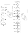
次に、図2および図3のフローチャートを用いて、上記構成のストロボ装置に外部電源を接続されていた時と接続されていない時の動作について、それぞれ説明する。 Next, the operations when the external power supply is connected to the strobe device having the above-described configuration and when it is not connected will be described using the flowcharts of FIGS.
ストロボ装置側の電源スイッチ2がオンされると、DC/DCコンバータ4が起動し、不図示の公知のリセット回路が作動してストロボマイコン8が動作状態となり、該ストロボマイコン8は、図2のステップ#101を介してステップ#102からの動作を開始する。
When the
ステップ#102では、ポートP2の状態より外部電源が接続されているかを判定し、ローレベルであれば外部電源が接続されているとしてステップ#103に進む。一方、ハイレベルであれば、ステップ#115へ進む。なお、ポートP2は無負荷時にはハイレベルとなっているものとする。詳しくは、ポートP2がローレベルの場合は、ポートP2が接続端子TC2,TG2,TG3,TC3を介して電源電池1のマイナス極であるグランドレベルとなっている状態であり、上記のように外部電源が接続されていると判定して、ステップ#103へ進み、ハイレベルの場合は、接続端子TC2に何も接続されていない状態であり、外部電源は接続されていないと判定して、ステップ#115へ進む。
In
外部電源が接続されているとしてステップ#103ヘ進むと、ポートP1をハイレベルとする。これにより、接続端子TC1、接続端子TG1及び抵抗38を介して、外部電源のトランジスタ27がオンするとともにトランジスタ25もオンし、DC/DCコンバータ29が起動し、外部電源が作動状態となる。外部電源の動作については、図3のフローチャ−トにより詳述する。なお、ポートP1は通常はローレベルである。
If the external power supply is connected and the process proceeds to step # 103, the port P1 is set to the high level. As a result, the
次のステップ#104では、ストロボマイコン8は、ポートP6をハイレベルとする。これにより、昇圧回路7が昇圧動作を開始し、ダイオード9を介してメインコンデンサ14への充電が開始される。なお、ポートP6は通常はローレベルである。続くステップ#105では、コンデンサ3の電圧(図2のフローでは、C3と記す)、即ち電源電池1の電圧を判定し、2Vより高い場合はステップ#106へ進み、2V以下の時は後述するステップ#112以降の動作へ進む。
In the
電源電池1の電圧が2Vより高いとしてステップ#106ヘ進んだ場合、ストロボマイコン8は、ポートP6のハイレベルを維持する。これにより昇圧動作が持続する。次のステップ#107では、ポートP3を介してメインコンデンサ14の充電電圧(図2のフローでは、C14と記す)を判定し、閃光放電管17に撮影に必要なだけの光量を発光させることのできる発光許可電圧である270Vに達していない時はこのステップ#107に留まる。その後、メインコンデンサ14の充電電圧が270Vに達するとステップ#108ヘ進み、ポートP4をハイレベルとする。これにより、LED6が点灯し、前述したように使用者がストロボ発光可能になったことを認識することができる。続くステップ#109では、メインコンデンサ14の充電電圧をポートP3を介して検出し、320Vに達したかを判定する。この結果、達していなければ達するまでこのステップ#109に留まり、その後、320Vに達するとステップ#110へ進み、ポートP6をローレベルとする。これにより、昇圧動作が停止する。
When the voltage of the power supply battery 1 is higher than 2V and the process proceeds to step # 106, the flash microcomputer 8 maintains the high level of the port P6. As a result, the boosting operation is continued. In the
次のステップ#111では、ストロボマイコン8は、メインコンデンサ14の充電電圧が降下し、317Vより低くなったかを、ポートP3の電圧を検出することにより判定する。この結果、317Vより低く降下していればステップ#108に戻り、降下していなければこのステップ#111に留まる。
In the
上記メインコンデンサ14の充電電圧の降下は、抵抗11,12及びメインコンデンサ14の漏れ電流等により生じる。しかしながら、ストロボ装置側の昇圧回路7と外部電源側の昇圧回路30が同時にメインコンデンサ14に対して充電を行い、外部電源によるメインコンデンサ14への充電電圧の方が高いので、一般的な使用では、ステップ#111からステップ#108に戻ることはない。但し、例外的には外部電源で消耗した電池を電源電池21として用いた場合は、ステップ#108に戻る可能性がある。
The drop in the charging voltage of the
上記したようにステップ#105にて、コンデンサ3の電圧(C3)が2V以下の時は、ストロボマイコン8は、ステップ#112に進む。そして、このステップ#112では、ポートP6をローレベルとする。これにより、昇圧回路7が動作を停止する。この動作停止により電源電池1の電流が減少するので、該電源電池1の電圧が上昇する。次のステップ#113では、ポートP5を介してコンデンサ3、即ち電源電池電圧1を判定し、2V以下の場合はこのステップ#113に留まり、2Vより高い時はステップ#104に戻り、以下、同様の動作を繰り返す。上記ステップ#105→#112→#113→#104のループは、電源電池1の電圧を監視し、DC/DCコンバータ4の動作電圧がその作動電圧以下にならないようにするために設けられている。
As described above, when the voltage (C3) of the capacitor 3 is 2 V or less at
また、上記したようにステップ#102にて、ポートP2がハイレベル、即ち外部電源が接続されていないと判定した場合は、ストロボマイコン8は、ステップ#115へ進む。そして、ステップ#115にて、ポートP6をハイレベルとする。これにより、昇圧回路7が昇圧動作を開始し、ダイオード9を介してメインコンデンサ14への充電が開始される。このステップ#115から先の動作は、外部電源が接続されていない場合の動作である。
If it is determined in
次のステップ#116では、ストロボマイコン8は、ポートP5を介してコンデンサ3の電圧、即ち電源電池1の電圧を判定し、2Vより高い時はステップ#117へ進み、2V以下の時は後述するステップ#122以降の動作へ進む。
In the
電源電池電圧1が2Vより高いとしてステップ#117ヘ進むと、ストロボマイコン8は、ポートP3を介してメインコンデンサ14の電圧を判定し、該メインコンデンサ14の電圧が270Vに達していない時はこのステップ#117に留まる。その後、270Vに達したことを判定するとステップ#118へ進み、ポートP4をハイレベルとする。これにより、上記したようにLED6が点灯し、使用者が、ストロボが発光可能になったことを認識することができる。
When the power supply battery voltage 1 is higher than 2V and the process proceeds to step # 117, the flash microcomputer 8 determines the voltage of the
次のステップ#119では、ストロボマイコン8は、メインコンデンサ14の充電電圧をポートP3で検出し、330Vに達したかを判定する。達していなければこのステップ#119に留まり、その後、達したことを判定するとステップ#120へ進む。上記メインコンデンサ14への充電電圧のレベル(330V)は、EEPROM10に書き込まれており、このEEPROM10の内容を書き換えることにより、変更可能である。本実施例1では外部電源接続時のステップ♯109では320Vに設定されているが、他の値を採用することもできる。次のステップ#120ヘ進むと、ポートP6をローレベルとする。これにより、昇圧回路7の昇圧動作が停止する。続くステップ#121では、メインコンデンサ14が327Vより低くなったかをポートP3の電圧を検出することで判定し、327Vより低くなっていればステップ#118に戻り、降下していなければこのステップ#121に留まる。上記と同様、メインコンデンサ14の充電電圧の降下は、抵抗11,12及びメインコンデンサ14の漏れ電流等により生じる。
In the
上記したようにステップ#116にて、コンデンサ3の電圧が2V以下の時は、ストロボマイコン8は、ステップ#122に進む。そして、このステップ#122では、ポートP6をローレベルとする。これにより、昇圧回路7が動作を停止する。この動作停止により電源電池1の電流が減少するので、該電源電池1の電圧は上昇する。次のステップ#123では、ポートP5を介してコンデンサ3、即ち電源電池1の電圧を判定し、2V以下の場合はこのステップ#123に留まり、2Vより高い時はステップ#115に戻り、以下、同様の動作を繰り返す。上記ステップ#116→#122→#123→#115のループは、電源電池1の電圧を監視し、DC/DCコンバータ4の動作電圧がその作動電圧以下にならないようにするために設けられている。
As described above, when the voltage of the capacitor 3 is 2 V or less at
上記の図2のフローチャートでの説明で分かるように、外部電源がストロボ装置に接続されている時は、メインコンデンサ14を320Vまで充電(#109)し、外部電源が接続されていない時は330Vまで充電(#119)されることになる。
As can be seen from the description of the flowchart of FIG. 2 above, when the external power supply is connected to the strobe device, the
次に、外部電源側の動作について、図3のフローチャートを用いて説明する。 Next, the operation on the external power supply side will be described using the flowchart of FIG.
外部電源の接続端子TG1に、ストロボマイコン8のポートP1からハイレベルの信号が入力されると、トランジスタ27がオンするとともにトランジスタ25もオンし、DC/DCコンバータ29が起動し、外部電源マイコン31の電源端子VDDに電圧が与えられる。すると、該外部電源マイコン31は、図3のステップ#201を介してステップ#202からの動作を開始する。
When a high level signal is input from the port P1 of the stroboscopic microcomputer 8 to the connection terminal TG1 of the external power supply, the
ステップ#202では、外部電源マイコン31は、ポートP1をハイレベルとし、昇圧回路30の動作を開始してコンデンサ36への充電を開始する。また同時に、ダイオード37および13を介してメインコンデンサ14への充電を開始する。そして、次のステップ#203にて、ポートP3を介してコンデンサ23の電圧(図3のフローでは、C23と記す)を判定し、2Vより高い時はステップ#204に進み、2V以下の時は後述するステップ#208以降の動作を行う。
In
コンデンサC23の電圧が2Vよりも高いとしてステップ#204ヘ進むと、外部電源マイコン31は、ポートP1のハイレベルを維持する。これにより、昇圧動作が持続する。この時、ダイオード37および13を介してメインコンデンサ14への充電を行う。従って、メインコンデンサ14はストロボ装置側の昇圧回路7と外部電源側の昇圧回路30の両者により充電されるので、上記昇圧回路7単独による充電より高速に充電が行われることになる。次のステップ#205では、コンデンサ36の電圧(図3のフローでは、C36と記す)をポートP2を介して検出し、330Vに達したかを判定する。この結果、330Vに達していなければこのステップ#205に留まり、その後、330Vに達するとステップ#206へ進む。上記コンデンサ36の電圧レベル(330V)は、EEPROM32に書き込まれており、このEEPROM32の内容を書き換えることにより、本実施例1では330Vであるが、他の値を採用することもできる。
If the voltage of the capacitor C23 is higher than 2V and the process proceeds to step # 204, the external
ステップ#206ヘ進むと、外部電源マイコン31は、ポートP1をローレベルとする。これにより、昇圧動作が停止する。そして、次のステップ#207にて、コンデンサ36が327Vより低いかを、ポートP3の電圧を検出することにより判定する。この結果、327Vより低ければステップ#204に戻り、降下していなければステップ#207に戻る。上記コンデンサ36の電圧の降下は、抵抗34,35およびコンデンサ36の漏れ電流等により生じる。
In
上記したようにステップ#203にて、コンデンサ23(C23)の電圧が2V以下の時は、外部電源マイコン31は、ステップ#208へ進む。そして、このステップ#208にて、ポートP1をローレベルとする。これにより、昇圧回路30が動作を停止する。この動作停止により電源電池21の電流が減少するので、該電源電池21の電圧が上昇し、コンデンサ36の電圧も上昇する。次のステップ#209では、ポートP3を介してコンデンサ36の電圧を判定し、2Vより高い時はステップ#202に戻り、2V以下の時はこのステップ#209に留まる。上記ステップ#203→#208→#209→#202のループは、コンデンサ23の電圧を監視し、DC/DCコンバータ29の動作電圧がその作動電圧以下にならないようにするために設けられている。
As described above, when the voltage of the capacitor 23 (C23) is 2 V or less in
なお、ストロボ装置の閃光放電管17を、カメラのシンクロスイッチ16をオンしてトリガー回路15を駆動し、該閃光放電管17を発光させたときは、図2のフローチャートのステップ#102の処理へ戻る。
When the
以上説明したように、ストロボ装置単独で動作させるときは、メインコンデンサ14は330V(ヒステリシス電圧3V)で安定化し、ストロボ装置に外部電源が接続された時は、ストロボ装置の昇圧回路7は320Vまではメインコンデンサ14を充電するが、外部電源により約330V(ヒステリシス3V)までは外部電源によってメインコンデンサ14は充電される。ここで、約330Vとしたのは、ダイオード37,13の電圧降下があるため、約1Vの電圧降下が生じるからでる。
As described above, when the strobe device is operated alone, the
ここで、ステップ#109,#119,#205で述べた判定電圧を、以下レギュレータ電圧と呼ぶ。外部電源が接続された時のストロボ装置のレギュレータ電圧を、外部電源が接続されていない時のレギュレータ電圧と変えた理由について説明する。 Here, the determination voltages described in steps # 109, # 119, and # 205 are hereinafter referred to as regulator voltages. The reason why the regulator voltage of the strobe device when the external power supply is connected is changed to the regulator voltage when the external power supply is not connected will be described.
ストロボ発光を繰り返した場合、ストロボ装置の電源電池と外部電源の電源電池がほぼ同時に無くなることが理想であるが、次のような現象が起こることがある。ストロボ発光を繰り返した場合において、ストロボ装置側の昇圧回路の充電能力が高いと、外部電源を使用した時、上記レギュレータ電圧が同じであるとストロボ装置の電源電池の消耗が外部電源の電源電池の消耗より早くなることがある。この場合、ストロボ装置の電源電池が先に消耗してしまうので、ストロボ動作が停止してしまう。ストロボ動作が停止すると、ストロボマイコン8も停止するので、ストロボ装置よりの信号で外部電源のトランジスタ27がオフとなり、外部電源の昇圧動作は停止してしまう。この場合、外部電源の電源電池にはエネルギーが残ってしまい、外部電源の電池を有効に利用できない。即ち、発光可能な回数が減ってしまう。この場合、外部電源使用時のストロボ装置の充電時のエネルギーを減少させればよい。
When strobe light emission is repeated, it is ideal that the power source battery of the strobe device and the power source battery of the external power source are almost eliminated at the same time, but the following phenomenon may occur. In the case of repeated flash firing, if the charging capability of the booster circuit on the strobe device is high, when the external power supply is used, if the regulator voltage is the same, the power supply battery of the strobe device will wear out. May be faster than exhausted. In this case, since the power source battery of the strobe device is consumed first, the strobe operation stops. When the stroboscopic operation is stopped, the stroboscopic microcomputer 8 is also stopped. Therefore, the
そこで、上記の実施例1は、外部電源使用時のストロボ装置のレギュレータ電圧を、外部電源不使用時のレギュレータ電圧より低く設定することにより、電源電池の消耗を減少させている。これにより、ストロボ装置の電源電池と外部電源の電源電池がほぼ同時に無くなるので、両者のエネルギーを有効に利用することができる。 Therefore, in the first embodiment, the regulator voltage of the strobe device when the external power source is used is set lower than the regulator voltage when the external power source is not used, thereby reducing power consumption. As a result, the power supply battery of the strobe device and the power supply battery of the external power supply are almost eliminated at the same time, so that the energy of both can be used effectively.
上記とは逆に、ストロボ装置の充電能力が低く、外部電源の充電能力が高い場合は、外部電源の電源電池が早く消耗してしまう。この場合、ストロボ装置の電源電池が主体でメインコンデンサ14を充電することになるので、該メインコンデンサ14の充電時間が急激に遅くなってしまう。この場合においても、ストロボ装置および外部電源の電源電池がほぼ同時に無くなることが理想である。よって、この場合は外部電源不使用時より外部電源使用時のストロボ装置のレギュレータ電圧を高く設定すればよい。
Contrary to the above, when the charging capability of the strobe device is low and the charging capability of the external power source is high, the power source battery of the external power source is quickly consumed. In this case, since the
ストロボ装置の外部電源接続時におけるレギュレータ電圧の決定方法は、ストロボ装置の電源電池および外部電源の電源電池の種類により実験的に決めればよい。図1の実施例1では、10Vだけストロボ装置の外部電源使用時のレギュレータ電圧を外部電源のレギュレータ電圧より低く設定してある。ストロボ装置の電源電池と外部電源の電源電池で同種類の電池を用いれば、ストロボ装置のレギュレータ電圧と外部電源のレギュレータ電圧の差を変更する必要の無い場合がほとんどである。 The method for determining the regulator voltage when the strobe device is connected to the external power source may be determined experimentally depending on the type of the power source battery of the strobe device and the power source battery of the external power source. In Example 1 of FIG. 1, the regulator voltage when the external power supply of the strobe device is used is set to be lower than the regulator voltage of the external power supply by 10V. If the same type of battery is used for the power supply battery of the strobe device and the power supply battery of the external power supply, there is almost no need to change the difference between the regulator voltage of the strobe device and the regulator voltage of the external power supply.
なお、一般的なストロボ装置と外部電源を接続して実験をした結果では、外部電源のレギュレータ電圧とストロボ装置のレギュレータ電圧の差は通常30V以内となっている。 As a result of experiments conducted by connecting a general strobe device and an external power source, the difference between the regulator voltage of the external power source and the regulator voltage of the strobe device is usually within 30V.
上記実施例1によれば、メインコンデンサ14を充電する昇圧回路7および該昇圧回路7の昇圧動作によりメインコンデンサ14の充電電圧が第1の所定範囲(例えば、320V〜317V)に至るように制御するストロボマイコン8とを有するストロボ装置と、メインコンデンサ14を充電するための外部電源としての出力電圧(コンデンサ36の電圧)を発生させる昇圧回路30と、該昇圧回路30の昇圧動作により前記出力電圧が第2の所定範囲(例えば、320V〜317V)に至るように制御する外部電源マイコン31とを有する外部電源とにより構成されるストロボシステムであって、前記ストロボ装置が、該ストロボ装置に外部電源が接続されたか否かを検出する検出手段(図2のステップ#102)を有しており、ストロボマイコン8が、前記検出手段により外部電源がストロボ装置に接続されていることが検出された場合に、メインコンデンサ14の充電電圧の第1の所定範囲または所定値を発光許可電圧よりも高い第3の所定範囲または所定値に変更する(図2のステップ#108〜#111)ようにしている。
According to the first embodiment, the booster circuit 7 that charges the
詳しくは、ストロボマイコン8は、昇圧回路8による充電能力に応じて、メインコンデンサ14の充電電圧の第1の所定範囲または所定値を、外部電源の出力電圧の第2の所定範囲または所定値より低い予め設定された電圧に変更する処理と、メインコンデンサ14の充電電圧の第1の所定範囲または所定値を、外部電源の出力電圧の第2の所定範囲または所定値より高い予め設定された電圧に変更する処理と、を切り替えるようにしている。
Specifically, the stroboscopic microcomputer 8 changes the first predetermined range or predetermined value of the charging voltage of the
上記構成とすることにより、従来のように複雑な回路構成をすることなく、ストロボ装置の電源電池1と外部電源の電源電池21がほぼ同時に無くなるようにすることができ、両者のエネルギーを有効に利用する。よって、ストロボ発光回数を増加させることができる。
By adopting the above configuration, the power supply battery 1 of the strobe device and the
次に、本発明の実施例2に係わるストロボシステムについて説明する。この実施例2は、実施例1における図2のフローチャートが、図4のフローチャートに変更になっていること以外は、図1の回路構成を含めて実施例1と同じである。
Next, a strobe system according to
図4において、図2と異なる点は、図2のステップ#111が無い点のみである。このようにすることにより、メインコンデンサ14の電圧がレギュレータ電圧になったら昇圧回路7の昇圧動作を停止し、その後の昇圧動作を行わない。しかし、外部電源よりメインコンデンサ14の充電が行われるので、動作としては実施例1と同じこととなる。従って、上記実施例2では、ストロボマイコン8は、メインコンデンサ14の充電電圧が所定値(例えば、320V)に至るように制御(図4のステップ#108〜#110)することになる。
4 is different from FIG. 2 only in that
この実施例2は、ステップ#111の動作が無くなるので、動作の簡素化が可能である。
In the second embodiment, since the operation of
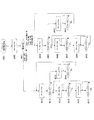
次に、本発明の実施例3に係わるストロボシステムについて説明する。図5は、本発明の実施例3に係わるストロボシステムの回路構成を示すブロック図であり、図中、点線より下の部分にストロボ装置を示し、点線より上の部分にストロボ装置に接続される外部電源を示している。 Next, a strobe system according to Embodiment 3 of the present invention will be described. FIG. 5 is a block diagram showing a circuit configuration of a strobe system according to the third embodiment of the present invention. In the figure, the strobe device is shown below the dotted line and connected to the strobe device above the dotted line. Indicates an external power supply.
先ず、ストロボ装置側の回路構成について説明する。 First, the circuit configuration on the strobe device side will be described.
図5において、101は電源電池であり、単三型電池4本直列接続で構成されている。102はスイッチであり、一端が電源電池101のプラス極に、他端が後述の昇圧回路107の入力端子に、それぞれ接続されている。103はコンデンサであり、電源電池101とスイッチ102の直列回路に並列に接続されている。104はDC/DCコンバータであり、一端がスイッチ102の他端に、他端が後述のストロボマイコン108の電源端子VDDに接続されている。105は抵抗であり、一端がストロボマイコン108のポートP4に、他端が後述のLED106のアノードに接続されている。106はLEDであり、アノードは抵抗5に、カソードは電源電池101のマイナス極に、それぞれ接続されている。このLED106は使用者が視認可能であり、一般的にはパイロットランプと呼ばれていて、該パイロットランプが点灯すると閃光発光が可能となる。107は後述のメインコンデンサ114を充電するための昇圧回路であり、入力端子がスイッチ102に、出力端子が後述のダイオード109のアノードに、制御端子がストロボマイコン108のポートP5に、それぞれ接続されている。108はストロボマイコンであり、5個のポートP1〜P5、3個の端子群FL1〜FL3、電源端子VDD、グランド端子GNDを有している。
In FIG. 5,
109はダイオードであり、アノードが昇圧回路107の出力端子に、カソードがメインコンデンサ114のプラス極に、それぞれ接続されている。110はEEPROMであり、ストロボマイコン108の端子群FL1に接続されている。111および112は直列に接続された抵抗であり、メインコンデンサ114に並列に接続されている。113はダイオードであり、アノードが外部電源との接続端子TC4に、カソードがメインコンデンサ114のプラス極に、それぞれ接続されている。114はメインコンデンサである。115は公知のトリガー回路であり、一端が後述のシンクロスイッチ116の一端に、他端が後述の閃光放電管117のトリガー電極に、それぞれ接続されている。116は不図示のカメラのシンクロスイッチであり、一端がトリガー回路115の一端に、他端がメインコンデンサ114のマイナス極に、それぞれ接続されている。117は閃光放電管であり、メインコンデンサ114と並列に接続されている。118は電池選択手段であり、複数のラインを介してストロボマイコン108の端子群FL2に接続されている。
次に、外部電源側について説明する。 Next, the external power supply side will be described.
図5において、121は電源電池であり、単三型電池8本の直列接続で構成されている。122はコンデンサであり、プラス極が電源電池121のプラス極に、マイナス極が電源電池21のマイナス極に、それぞれ接続されている。123はダイオードであり、アノードが電源電池121のプラス極に、カソードが後述の電圧安定化回路125の入力に、それぞれ接続されている。124はDC/DCコンバータであり、入力端子が電源電池121プラス極に、出力端子がダイオード123のカソードに、制御端子が後述の外部電源マイコン129のポートP4に、それぞれ接続されている。125は電圧安定化回路であり、入力端子がDC/DCコンバータの出力端子に、出力端子が外部電源マイコン129の電源端子VDDに、それぞれ接続されている。126は抵抗であり、一端が外部電源マイコン129のポートP3に、他端が後述のダイオード127のアノードに、それぞれ接続されている。127は外部電源の動作表示用LEDであり、アノードが抵抗126の一端に、カソードが電源電池121のマイナス端子に、それぞれ接続されている。このLED127で、外部電源が動作中であるかを使用者が確認することができる。
In FIG. 5,
128は昇圧回路であり、入力端子が電源電池121のプラス極に、出力端子が後述のダイオード130のアノードに、制御端子が後述の外部電源マイコン129のポートP1に、それぞれ接続されている。129は外部電源マイコン129であり、外部電源内の各制御を行い、5個のポートP1〜P5と3個の端子群GL1〜GL3を有している。131はEEPROMであり、外部電源マイコン129の端子群GL1に接続されている。132は使用する電池の種類を手動で設定することができる電池選択手段であり、外部電源マイコン129の端子群GL2に接続されている。133および134は直列に接続された抵抗であり、この直列抵抗は後述のコンデンサ135に並列に接続されている。また、抵抗133と134の接続点は外部電源マイコン129のポートP2に接続されている。135はコンデンサであり、一端がダイオード130のカソードに、他端が電源電池121のマイナス極に、それぞれ接続されている。136はダイオードであり、アノードがダイオード130のカソードに、カソードが接続端子TG4に、それぞれ接続されている。
A
TG1,TG2,TG3,TG4は外部電源側の接続端子であり、ストロボ装置側の接続端子TC1,TC2,TC3,TC4とそれぞれ接続されている。 TG1, TG2, TG3, and TG4 are connection terminals on the external power supply side, and are connected to connection terminals TC1, TC2, TC3, and TC4 on the strobe device side, respectively.
次に、図6および図7を用いて、ストロボ装置に外部電源が接続された時と接続されていない時の動作について詳述する。 Next, the operation when an external power supply is connected to the strobe device and when it is not connected will be described in detail with reference to FIGS.
電源スイッチ102がオンされると、DC/DCコンバータ104が起動し、不図示の公知のリセット回路が作動してストロボマイコン108が動作状態となり、該ストロボマイコン108は、図6のステップ#301を介してステップ#302からの動作を開始する。
When the
ステップ#302では、ストロボマイコン108は、ポートP1の状態から外部電源が接続されているかの判定を行い、ローレベルであれば外部電源が接続されているとしてステップ#303に進み、ハイレベルであれば外部電源が接続されていないとしてステップ#314に進む。なお、ポートP1は通常はハイレベルである。詳しくは、ストロボマイコン108は、ポートP1がローレベル場合は接続端子TC1,TG1,TG3,TC3を介して電源電池101のマイナス極であるグランドレベルとなっており、外部電源が接続されているとしてステップ#303に進み、ハイレベルの場合は接続端子TC1に何も接続されていない状態であり、外部電源が接続されていないとしてステップ#314に進む。また、ストロボマイコン108は、外部電源が接続されていると判定した時より外部電源マイコン129と端子群FL3、接続端子TC2,TG2、端子群GL3を介して通信を開始する。
In
外部電源が接続されているとしてステップ#303へ進むと、ストロボマイコン108は、上記外部電源マイコン129との通信の結果、ストロボ装置側の電源電池101および外部電源側の電源電池121の両者共、LR6(アルカリ電池)あるいはNi−MH(ニッケル水素電池)の種類の電池と判定した時は、ステップ#304に進む。また、ストロボ装置側の電源電池101がLR6で、外部電源側の電源電池121がNi−MHであると判定した時は、ステップ#314に進む。また、ストロボ装置側の電源電池101がNi−MHで、外部電源側の電源電池121がLR6(アルカリ電池)と判定した時は、ステップ#324に進む。電源電池の種類の判定は、共に挿入される電池の種類を手動で使用者が設定しているものとし、ストロボ装置側では電池選択手段118が、外部電源側では電池選択手段132が、その設定に応じて電池の種類を判定するものとする。
When the process proceeds to step # 303 assuming that the external power source is connected, the
上記ステップ#303にて、外部電源マイコン129との通信により外部電源に設定されている電池を認識する。その結果、ストロボ装置側の電源電池101および外部電源側の電源電池121の両者共、LR6(アルカリ電池)あるいはNi−MH(ニッケル水素電池)の電池であるとしてステップ#304へ進むと、ストロボマイコン108は、ポートP5をハイレベルとする。これにより、昇圧回路107が昇圧動作を開始し、ダイオード109を介してメインコンデンサ114への充電が開始される。なお、ポートP5は通常はローレベルである。次のステップ#305では、ポートP3でコンデンサ103(図6のフローでは、C103と記す)の電圧(図6のフローでは、C103と記す)、即ち電源電池101の電圧を判定し、2Vより高い時はステップ#306に進み、2V以下の時は後述するステップ#312以降の動作へ進む。
In
電源電池101の電圧が2Vより高いとしてステップ#306ヘ進むと、ストロボマイコン108は、ポートP5のハイレベルを維持する。これにより、昇圧動作が行われる。そして、次のステップ#307にて、ポートP2を介してメインコンデンサ14の充電電圧(図6のフローでは、C114と記す)を判定し、閃光放電管117に撮影に必要なだけの光量を発光させることのできる発光許可電圧である270Vに達していなければこのステップ#307に留まる。その後、270Vを越えるとステップ#308に進み、ポートP4をハイレベルとする。これにより、LED106が点灯し、使用者が、ストロボ発光可能になったことを認識することができる。次のステップ#309では、メインコンデンサ114の電圧をポートP2で検出し、320Vを越えたかを判定する。この結果、320V以下であればこのステップ#309に留まり、その後、320Vに達するとステップ#310へ進む。上記メインコンデンサ電圧のレベル(320V)はEEPROM110に書き込まれており、このEEPROM110の内容を書き換えることにより、本実施例3では320Vであるが、他の値を採用することもできる。
When the voltage of the
次のステップ#310では、ストロボマイコン108は、ポートP5をローレベルとする。これにより、昇圧動作は停止する。続くステップ#311では、メインコンデンサ114の充電電圧が降下し、317V以下になったかを、ポートP2の電圧を検出することにより判定する。317V以下に降下していればステップ#308に戻り、降下していなければステップ#311に戻る。上記メインコンデンサ114の電圧の降下は、抵抗111,112およびメインコンデンサ114の漏れ電流等により生じる。しかしながら、後述するように、ストロボ装置側の昇圧回路107と外部電源側の昇圧回路128が同時にメインコンデンサ114を充電するが、外部電源によるメインコンデンサ114の充電電圧の方が高いので、一般的な使用では、ステップ#311からステップ#308に処理が戻ることはない。但し、例外的に外部電源で消耗した電池を電源電池121として用いた場合は、ステップ#308に戻る可能性がある。
In the
上記したようにステップ#305にて、電源電池101の電圧が2V以下であるとしてステップ#312へ進むと、ストロボマイコン108は、ポートP5をローレベルとする。これにより、昇圧回路107が動作を停止する。この動作停止により電源電池101の消費電流が減少し、該電源電池101の電圧が上昇する。次のステップ#313では、ポートP3を介してコンデンサ103の電圧、即ち電源電池101の電圧を判定し、2Vより高い時はステップ#304に戻り、2V以下の時はステップ#313に戻る。上記ステップ#305→ステップ#312→#313→#304のループは、電源電池101の電圧を監視し、DC/DCコンバータ104の動作電圧がその作動電圧以下にならないようにするために設けられている。
As described above, when the voltage of the
また、上記したようにステップ#303にて、ストロボ装置側の電源電池101がLR6で、外部電源側の電源電池121がNi−MHの時は、ストロボマイコン108は、ステップ#314〜#322の動作を実行する。このステップ#314〜#322の動作は、上記ステップ#304〜#313と同様であるので、その説明は省略する。但し、ステップ#319,#321の判定電圧は330V,327Vである。
As described above, when the
また、上記したようにステップ#303にて、ストロボ装置側の電源電池101がNi−MHで、外部電源側の電源電池121がLR6の時は、ステップ#324以降の動作に進む。このステップ#324以降の動作は図示していないが、上記ステップ#304〜#313とほぼ同じ動作であり、異なるのは、ステップ#309での判定電圧が310Vであること、および、ステップ#311での判定電圧が307Vであること、のみが異なるので、これ以上の説明は割愛する。
Further, as described above, when the
次に、外部電源側での動作について、図7のフローチャート用いて説明する。外部電源に電池が装着されると、外部電源マイコン129はスタンバイ状態となり、図7のステップ#401を介してステップ#402からの動作を開始する。
Next, the operation on the external power supply side will be described using the flowchart of FIG. When the battery is attached to the external power supply, the external
先ず、ステップ#402では、外部電源マイコン129は、ストロボ装置に外部電源が接続されていると判定した時よりストロボマイコン108と端子群FL3、接続端子TC2,TG2、端子群GL3を介して通信を開始する。この通信の開始により、ポートP4をハイレベルにしてDC/DCコンバータ124を起動し、通常モードでの動作を開始する。また同時に、ポートP3をハイレベルにしてLED127を点灯する。この点灯を使用者が視認することにより、外部電源が動作をしていることを確認することができる。なお、ストロボ装置から取り外されると、再びスタンバイモードに戻る。
First, in
次のステップ#403では、外部電源マイコン129は、ストロボ装置と外部電源の電源電池を判定する。上記ストロボマイコン108との通信の結果、ストロボ装置側の電源電池101および外部電源の電源電池121の両者がLR6あるいはNi−MHの時、および、ストロボ装置側の電源電池101がNi−MHで、外部電源の電源電池121がLR6の時は、ステップ#404に進む。一方、ストロボ装置側の電源電池101がLR6で、外部電源側の電源電池121がNi−MHの時は、ステップ#412に進む。
In the
次のステップ#404では、外部電源マイコン129は、ポートP1をハイレベルとする。これにより、昇圧回路128が昇圧動作を開始し、ダイオード130を介してコンデンサ135の充電が行われる。また同時に、ダイオード136,113を介してメインコンデンサ114への充電も行われる。なお、ポートP1は通常はローレベルである。続くステップ#405では、ポートP4を介してコンデンサ122(図7では、C122と記す)の電圧(図7では、C122と記す)、即ち電源電池121の電圧を判定し、2Vより高い時はステップ#406に進み、2V以下の時はステップ#410に進む。
In the
電源電池121の電圧が2Vより高いとしてステップ#406ヘ進むと、外部電源マイコン129は、ポートP1のハイレベルを維持する。これにより、昇圧動作が行われる。次のステップ#407では、コンデンサ135の電圧(図7では、C135と記す)が330Vに達したかをポートP2の電圧を検出することにより判定する。この結果、330Vに達していなければこのステップ#407に留まり、その後、330Vに達することによりステップ#408へ進む。上記電圧のレベル(330V)は、EEPROM131に書き込まれている。
If the voltage of the
次のステップ#408では、外部電源マイコン129は、ポートP1をローレベルとする。これにより、昇圧動作が停止する。そして、次のステップ#409にて、コンデンサ135の電圧が降下し、327Vより低くなったかをポートP2の電圧を検出することにより判定する。この結果、327Vより低く降下していればステップ#406に戻り、降下していなければステップ#409に戻る。上記コンデンサ135の電圧の降下は、抵抗133、134およびコンデンサ135の漏れ電流等により生じる。
In the
上記ステップ405にて電源電池121の電圧が2V以下と判定して、ステップ#410に進むと、ポートP1をローレベルとする。これにより、昇圧回路128が動作を停止する。この動作停止により、電源電池の消費電流が減少し、電源電池121の電圧が上昇する。続くステップ#411では、ポートP5でコンデンサ122の電圧、即ち電源電池121の電圧を判定し、2Vより高い時はステップ#404に戻り、2V以下の時はステップ#411に戻る。上記ステップ#405→#410→#411→#404のループは、電源電池121の電圧を監視し、DC/DCコンバータ124の動作電圧がその作動電圧以下にならないようにするために設けられている。
If it is determined in
また、上記ステップ#403にて、ストロボ装置側の電源電池101がLR6で、外部電源側の電源電池121がNi−MHであるとしてステップ#412に進むと、ここではステップ#412〜#418の動作を実行する。なお、このステップ#412〜#418の動作は、以下に述べる点を除き、上記ステップ#404〜#411と同じなので、以下に述べる点以外の説明は省略する。
In
上記との違いは、ステップ#415の判定電圧が320Vであること、及び、ステップ#317の判断電圧が317Vであること、のみである。
The only difference from the above is that the determination voltage in
実施例3は、上記の説明でも明らかなように、ストロボ装置の電源電池と外部電源の電源電池の種類を判定して、各々のレギュレータ電圧を変えている。 As is apparent from the above description, the third embodiment determines the types of the power supply battery for the strobe device and the power supply battery for the external power supply, and changes the regulator voltage.
例えば、ストロボ装置と外部電源の電源電池が同一の種類であるときは、ストロボ装置の外部電源使用時のレギュレータ電圧を320V、外部電源不使用時のレギュレータ電圧を330Vとしている。また、外部電源のレギュレータ電圧も330Vとしている。 For example, when the power source battery of the strobe device and the external power source is the same type, the regulator voltage when the strobe device uses the external power source is 320 V, and the regulator voltage when the external power source is not used is 330 V. The regulator voltage of the external power supply is also 330V.
また、ストロボ装置の電源電池がLR6(アルカリ電池)であり、外部電源の電源電池がNi−MH(ニッケル水素電池)である場合は、ストロボ装置のレギュレータ電圧を330Vとし、外部電源のレギュレータ電圧を320Vとしている。これは、一般的にニッケル水素電池の充電能力が高く、ストロボ装置の電源電池よりも先に消耗してしまうことを防ぐために、外部電源の方のレギュレータ電圧を低く設定してある。 When the power supply battery of the strobe device is LR6 (alkaline battery) and the power supply battery of the external power supply is Ni-MH (nickel metal hydride battery), the regulator voltage of the strobe device is set to 330 V, and the regulator voltage of the external power supply is set to 320V. This is because the nickel-metal hydride battery generally has a high charging capacity, and the regulator voltage of the external power supply is set lower in order to prevent the battery from being consumed before the power supply battery of the strobe device.
また、ストロボ装置の電源電池がニッケル水素電池であり、外部電源電池の電源電池がアルカリ電池である場合は、上述の様に、ニッケル水素電池の方の充電能力が高いので、ストロボ装置の電源電池の方が先に消耗してしまうことを防ぐために、ストロボ装置のレギュレータ電圧を310Vに設定し、外部電源のレギュレータ電圧を330Vに設定している。 Also, when the power supply battery of the strobe device is a nickel metal hydride battery and the power supply battery of the external power supply battery is an alkaline battery, as described above, the charge capacity of the nickel metal hydride battery is higher, so the power supply battery of the strobe device Therefore, the regulator voltage of the strobe device is set to 310V, and the regulator voltage of the external power supply is set to 330V.
以上により、ストロボ発光動作を繰り返した場合、ほぼ同時にストロボ装置と外部電源の電源電池が消耗し、電池のエネルギーの無駄を防ぎ、ストロボの発光回数を増すことができる。 As described above, when the stroboscopic light emitting operation is repeated, the power source battery of the stroboscopic device and the external power source is consumed almost at the same time.
なお、現在、上記の以外の電池Ni−cd電池、ニッケル電池、リチウム電池等が発売されているが、各電池の組み合わせに最適なストロボ装置と外部電源のレギュレータ電圧を実験的に求め、EEPROMにその値を記憶させておくことにより、ストロボ装置および外部電源にそれぞれ備わっている電池選択手段による選択結果に基づいてそれらの値を読み出し、ストロボ装置と外部電源を組み合わせて使用するときに最適なレギュレータ電圧を得ることができる。 Currently, Ni-cd batteries, nickel batteries, lithium batteries, etc. other than those mentioned above are on the market, but the optimum strobe device for each battery combination and the regulator voltage of the external power supply are experimentally determined and stored in the EEPROM. By storing these values, the regulators are optimally used when the strobe device and the external power supply are used in combination by reading out those values based on the selection results by the battery selection means provided in the strobe device and the external power supply. A voltage can be obtained.
また、不図示であるが、自動的に電池の無負荷時の電圧および内部抵抗を測定することにより、電池の種類を判定し、最適なストロボ装置と外部電源のレギュレータ電圧を設定することも可能である。 Although not shown, it is also possible to determine the battery type by automatically measuring the battery's no-load voltage and internal resistance, and to set the optimum strobe device and regulator voltage for the external power supply. It is.
上記の各実施例においては、フル発光タイプのストロボ装置に適用したが、発光を制御するタイプのストロボ装置に適用することも可能である。 In each of the above-described embodiments, the present invention is applied to a full-flash type strobe device, but it is also possible to apply to a strobe device that controls light emission.
1 ストロボ装置側の電源電池
7 昇圧回路
8 ストロボマイコン
10 EEPROM
14 メインコンデンサ
17 閃光放電管
21 外部電源側の電源電池
30 昇圧回路
31 外部電源マイコン
32 EEPROM
36 コンデンサ
101 ストロボ側の電源電池
107 昇圧回路
108 ストロボマイコン
110 EEPROM
118 電池選択手段
114 メインコンデンサ
117 閃光放電管
121 外部電源側の電源電池
128 昇圧回路
129 外部電源マイコン
131 EEPROM
132 電池選択手段
135 コンデンサ
1 Power Supply Battery on Strobe Device 7 Booster Circuit 8
14
36
118
132 battery selection means 135 capacitor
Claims (4)
前記メインコンデンサを充電するための外部電源としての出力電圧を発生させる第2の昇圧手段と、該第2の昇圧手段の昇圧動作により前記出力電圧が第2の所定範囲または所定値に至るように制御する第2の制御手段とを有し、前記ストロボ装置に接続される外部電源とにより構成されるストロボシステムであって、
前記第1の制御手段は、前記第1の昇圧手段による充電能力が前記第2の昇圧手段による充電能力よりも高い場合には、前記メインコンデンサの充電電圧の第1の所定範囲または所定値を、前記外部電源の出力電圧の第2の所定範囲または所定値より低い電圧に変更し、前記第1の昇圧手段による充電能力が前記第2の昇圧手段による充電能力よりも低い場合には、前記メインコンデンサの充電電圧の第1の所定範囲または所定値を、前記外部電源の出力電圧の第2の所定範囲または所定値より高い電圧に変更することを特徴とするストロボシステム。 First boosting means for charging the main capacitor, and first control means for controlling the charging voltage of the main capacitor to reach a first predetermined range or a predetermined value by the boosting operation of the first boosting means. A strobe device having
Second boosting means for generating an output voltage as an external power source for charging the main capacitor, and the output voltage reaches a second predetermined range or a predetermined value by the boosting operation of the second boosting means. A strobe system comprising a second control means for controlling and an external power source connected to the strobe device ,
The first control unit sets a first predetermined range or a predetermined value of the charging voltage of the main capacitor when the charging capability by the first boosting unit is higher than the charging capability by the second boosting unit. The output voltage of the external power supply is changed to a voltage lower than a second predetermined range or a predetermined value, and when the charging capability by the first boosting means is lower than the charging capability by the second boosting means, A strobe system , wherein a first predetermined range or a predetermined value of the charging voltage of the main capacitor is changed to a voltage higher than a second predetermined range or a predetermined value of the output voltage of the external power supply .
前記制御手段は、前記昇圧手段による充電能力が前記メインコンデンサを充電するための外部電源による充電能力よりも高い場合には、前記昇圧手段による充電能力が前記外部電源による充電能力よりも低い場合に比べて、前記メインコンデンサの充電電圧の所定範囲または所定値を低い電圧に変更することを特徴とするストロボ装置。 A strobe device comprising boosting means for charging a main capacitor, and control means for controlling the charging voltage of the main capacitor to reach a predetermined range or a predetermined value by boosting operation of the boosting means ,
When the charging capability by the boosting means is higher than the charging capability by the external power supply for charging the main capacitor, the control means is when the charging capability by the boosting means is lower than the charging capability by the external power supply. In comparison, the strobe device is characterized in that a predetermined range or a predetermined value of the charging voltage of the main capacitor is changed to a lower voltage .
前記メインコンデンサを充電するための外部電源としての出力電圧を発生させる第2の昇圧手段と、該第2の昇圧手段の昇圧動作により前記出力電圧が第2の所定範囲または所定値に至るように制御する第2の制御手段とを有し、前記ストロボ装置に接続される外部電源とにより構成されるストロボシステムであって、
前記ストロボ装置及び前記外部電源に使用される電源電池の種類を判定する判定手段を有し、
前記第1の制御手段は、前記判定手段により判定された前記ストロボ装置の電源電池による充電能力が前記外部電源の電源電池による充電能力よりも高い場合には、前記メインコンデンサの充電電圧の第1の所定範囲または所定値を、前記外部電源の出力電圧の第2の所定範囲または所定値より低い電圧に変更し、前記ストロボ装置の電源電池による充電能力が前記外部電源の電源電池による充電能力よりも低い場合には、前記メインコンデンサの充電電圧の第1の所定範囲または所定値を、前記外部電源の出力電圧の第2の所定範囲または所定値より高い電圧に変更することを特徴とするストロボシステム。 First boosting means for charging the main capacitor, and first control means for controlling the charging voltage of the main capacitor to reach a first predetermined range or a predetermined value by the boosting operation of the first boosting means. A strobe device having
Second boosting means for generating an output voltage as an external power source for charging the main capacitor, and the output voltage reaches a second predetermined range or a predetermined value by the boosting operation of the second boosting means. A strobe system comprising a second control means for controlling and an external power source connected to the strobe device,
Determining means for determining the type of power supply battery used for the strobe device and the external power supply;
When the charging capability of the power supply battery of the strobe device determined by the determination unit is higher than the charging capability of the power supply battery of the external power source, the first control unit determines the first charging voltage of the main capacitor. Is changed to a voltage lower than a second predetermined range or a predetermined value of the output voltage of the external power supply, and the charging capacity of the strobe device by the power supply battery is more than the charging capacity of the power supply battery of the external power supply. If also low, strobe and changes the first predetermined range or a predetermined value of the charging voltage of the main capacitor, the second predetermined range or a voltage higher than a predetermined value of the output voltage of the external power supply System .
前記ストロボ装置及び前記メインコンデンサを充電するための外部電源に使用される電源電池の種類を判定する判定手段を有し、
前記制御手段は、前記判定手段により判定された前記ストロボ装置の電源電池による充電能力が前記外部電源の電源電池による充電能力よりも高い場合には、前記ストロボ装置の電源電池による充電能力が前記外部電源の電源電池による充電能力よりも低い場合に比べて、前記メインコンデンサの充電電圧の所定範囲または所定値を低い電圧に変更することを特徴とするストロボ装置。 A strobe device comprising boosting means for charging a main capacitor, and control means for controlling the charging voltage of the main capacitor to reach a predetermined range or a predetermined value by boosting operation of the boosting means,
A determination means for determining a type of a power battery used as an external power source for charging the strobe device and the main capacitor;
When the charging capability of the strobe device determined by the determination unit is higher than the charging capability of the power source battery of the external power source, the control unit determines that the charging capability of the strobe device by the power source battery is the external power source. A strobe device , wherein a predetermined range or a predetermined value of the charging voltage of the main capacitor is changed to a lower voltage as compared with a case where the charging capacity of the power source is lower than that of a power source battery .
Priority Applications (1)
| Application Number | Priority Date | Filing Date | Title |
|---|---|---|---|
| JP2004238075A JP4447987B2 (en) | 2004-08-18 | 2004-08-18 | Strobe system and strobe device |
Applications Claiming Priority (1)
| Application Number | Priority Date | Filing Date | Title |
|---|---|---|---|
| JP2004238075A JP4447987B2 (en) | 2004-08-18 | 2004-08-18 | Strobe system and strobe device |
Publications (3)
| Publication Number | Publication Date |
|---|---|
| JP2006058423A JP2006058423A (en) | 2006-03-02 |
| JP2006058423A5 JP2006058423A5 (en) | 2007-10-04 |
| JP4447987B2 true JP4447987B2 (en) | 2010-04-07 |
Family
ID=36105951
Family Applications (1)
| Application Number | Title | Priority Date | Filing Date |
|---|---|---|---|
| JP2004238075A Expired - Fee Related JP4447987B2 (en) | 2004-08-18 | 2004-08-18 | Strobe system and strobe device |
Country Status (1)
| Country | Link |
|---|---|
| JP (1) | JP4447987B2 (en) |
Families Citing this family (1)
| Publication number | Priority date | Publication date | Assignee | Title |
|---|---|---|---|---|
| JP2014016573A (en) * | 2012-07-11 | 2014-01-30 | Ricoh Co Ltd | Imaging device |
-
2004
- 2004-08-18 JP JP2004238075A patent/JP4447987B2/en not_active Expired - Fee Related
Also Published As
| Publication number | Publication date |
|---|---|
| JP2006058423A (en) | 2006-03-02 |
Similar Documents
| Publication | Publication Date | Title |
|---|---|---|
| US11205920B2 (en) | Emergency starting power supply and emergency start method | |
| JP2003259560A (en) | Charging circuit | |
| US20060029845A1 (en) | Fuel cell system | |
| US9807853B2 (en) | Lighting device, lighting system, and external power source device | |
| EP0495728B1 (en) | Battery charger | |
| JPH1094185A (en) | Battery charger | |
| JP4447987B2 (en) | Strobe system and strobe device | |
| JPH0219794Y2 (en) | ||
| US20140117863A1 (en) | Strobe Device and Electric Power Supply Method Therefor | |
| JPS633295B2 (en) | ||
| JP4816470B2 (en) | CHARGE CONTROL DEVICE, CHARGE CONTROL METHOD, CHARGE CONTROL PROGRAM | |
| JP4231257B2 (en) | camera | |
| KR100245007B1 (en) | Flash charge control apparatus and method according to battery voltage | |
| JPH0714261B2 (en) | Charger | |
| JP3165119B2 (en) | Charging circuit | |
| JP4212381B2 (en) | Camera with built-in flash | |
| JPH0246437A (en) | Camera with flashing device | |
| JP2691274B2 (en) | Charge state detection device for strobe circuit | |
| JPS6218906B2 (en) | ||
| JP2001215576A (en) | Light emission device, camera system and light emission communication system | |
| JPH0218536A (en) | Flash light photographing device | |
| JPH11289680A (en) | Electronic equipment and battery pack therefor | |
| JPH08179403A (en) | Stroboscopic consecutively photographing camera | |
| JPH01144329A (en) | Recharge circuit for battery | |
| JPS631823B2 (en) |
Legal Events
| Date | Code | Title | Description |
|---|---|---|---|
| A521 | Written amendment |
Free format text: JAPANESE INTERMEDIATE CODE: A523 Effective date: 20070815 |
|
| A621 | Written request for application examination |
Free format text: JAPANESE INTERMEDIATE CODE: A621 Effective date: 20070815 |
|
| A977 | Report on retrieval |
Free format text: JAPANESE INTERMEDIATE CODE: A971007 Effective date: 20090917 |
|
| A131 | Notification of reasons for refusal |
Free format text: JAPANESE INTERMEDIATE CODE: A131 Effective date: 20090929 |
|
| A521 | Written amendment |
Free format text: JAPANESE INTERMEDIATE CODE: A523 Effective date: 20091127 |
|
| TRDD | Decision of grant or rejection written | ||
| A01 | Written decision to grant a patent or to grant a registration (utility model) |
Free format text: JAPANESE INTERMEDIATE CODE: A01 Effective date: 20100119 |
|
| A01 | Written decision to grant a patent or to grant a registration (utility model) |
Free format text: JAPANESE INTERMEDIATE CODE: A01 |
|
| A61 | First payment of annual fees (during grant procedure) |
Free format text: JAPANESE INTERMEDIATE CODE: A61 Effective date: 20100121 |
|
| FPAY | Renewal fee payment (event date is renewal date of database) |
Free format text: PAYMENT UNTIL: 20130129 Year of fee payment: 3 |
|
| R150 | Certificate of patent or registration of utility model |
Free format text: JAPANESE INTERMEDIATE CODE: R150 |
|
| FPAY | Renewal fee payment (event date is renewal date of database) |
Free format text: PAYMENT UNTIL: 20140129 Year of fee payment: 4 |
|
| LAPS | Cancellation because of no payment of annual fees |