JP4447689B2 - Automatic video interpretation system - Google Patents
Automatic video interpretation system Download PDFInfo
- Publication number
- JP4447689B2 JP4447689B2 JP12772899A JP12772899A JP4447689B2 JP 4447689 B2 JP4447689 B2 JP 4447689B2 JP 12772899 A JP12772899 A JP 12772899A JP 12772899 A JP12772899 A JP 12772899A JP 4447689 B2 JP4447689 B2 JP 4447689B2
- Authority
- JP
- Japan
- Prior art keywords
- region
- digital video
- analyzer
- information
- video
- Prior art date
- Legal status (The legal status is an assumption and is not a legal conclusion. Google has not performed a legal analysis and makes no representation as to the accuracy of the status listed.)
- Expired - Fee Related
Links
Images


Classifications
-
- H—ELECTRICITY
- H04—ELECTRIC COMMUNICATION TECHNIQUE
- H04N—PICTORIAL COMMUNICATION, e.g. TELEVISION
- H04N19/00—Methods or arrangements for coding, decoding, compressing or decompressing digital video signals
- H04N19/50—Methods or arrangements for coding, decoding, compressing or decompressing digital video signals using predictive coding
- H04N19/503—Methods or arrangements for coding, decoding, compressing or decompressing digital video signals using predictive coding involving temporal prediction
- H04N19/51—Motion estimation or motion compensation
- H04N19/537—Motion estimation other than block-based
- H04N19/543—Motion estimation other than block-based using regions
-
- G—PHYSICS
- G06—COMPUTING; CALCULATING OR COUNTING
- G06V—IMAGE OR VIDEO RECOGNITION OR UNDERSTANDING
- G06V10/00—Arrangements for image or video recognition or understanding
- G06V10/70—Arrangements for image or video recognition or understanding using pattern recognition or machine learning
- G06V10/74—Image or video pattern matching; Proximity measures in feature spaces
- G06V10/75—Organisation of the matching processes, e.g. simultaneous or sequential comparisons of image or video features; Coarse-fine approaches, e.g. multi-scale approaches; using context analysis; Selection of dictionaries
Description
【0001】
【発明の属する技術分野】
本発明はデジタルビデオ信号の統計解析に関し、特に、意味ラベルに関する自動内容解釈のためのデジタルビデオ信号の統計解析に関する。ラベルは、その後、内容に基づく検索やビデオアブストラクトの生成などのタスクの基礎として利用できる。
【0002】
【従来の技術】
一般的には、デジタルビデオは、視覚シーンの時間的展開を表現する信号であると想定される。通常、この信号は関連する音声情報と共に符号化される(例えば、MPEG−2オーディオビジュアル符号化フォーマット)。場合によっては、ビデオ信号及び音声信号と共に、シーン又はシーンの捕捉に関する情報が符号化されるときもあるだろう。デジタルビデオは、典型的には、静止デジタル画像又はフレームのシーケンスにより表現され、各デジタル画像は複数のカラーチャネル(例えば、R、G、B)に対する画素輝度の集合から構成される。この表現の大部分は、視覚シーンが感知されるグリッド方式による。
【0003】
視覚信号の内容を音声信号の中に見出すことができ、又、音声信号の内容を視覚信号の中に見出すことができるという意味で、視覚信号と、関連する音声信号とは互いに相関関係にある場合が多い。この相関は、MPEG−4などの、符号化の単位が1つのシーンの中の空間的位置及び時間的位置を限定されたオーディオビジュアルオブジェクトである最近のデジタルオーディオビジュアル符号化フォーマットにおいては、明白に認められる。このようなオーディオビジュアル情報の表現は、デジタル素材の利用に、より適応するものであるが、自然のシーンの視覚成分は依然としてグリッドに基づく感知技法を使用して捕捉されるのが普通である(すなわち、デジタル画像はキャプチャ装置により規定されるフレームレートで感知される)。従って、通常、デジタルビデオ解釈のプロセスは依然としてデジタル画像解釈のプロセスを基礎としており、関連する音声信号とは別個に考慮されるのが普通である。
【0004】
デジタル画像信号の解釈は、画像中の意味のあるオブジェクト又は領域の識別を通して画像の内容を理解し且つそれらの空間的配列を解析するプロセスである。従来、画像解釈のタスクは人間による解析を必要としていた。これにはコストも、時間もかかり、そのため、自動画像解釈システムを構築すべく、多くの研究が重ねられてきた。
【0005】
既存の多くの画像解釈システムは低レベル処理と高レベル処理とを含む。通常、低レベル処理は、画像を画素輝度のアレイから辺と領域のような空間的に関連する画像プリミティブの集合に変換する。その後、プリミティブ(例えば、平均画素輝度)から様々な特徴を抽出することができる。高レベル処理では、画像ドメインの知識と特徴測定を利用して、プリミティブにオブジェクトラベル又は領域ラベル、すなわち、解釈を割り当て、それにより、「画像の中に何が存在しているか」に関する記述を構築する。
【0006】
初期の段階の画像解釈の試みは、個別のプリミティブをその特徴測定値に従って限られた数のオブジェクトクラスに分類することに基づいていた。この方式の成功には、低レベル処理で頻繁に発生する誤りを含む結果又は不完全な結果や、画像中の雑音に起因する特徴測定値の誤差によって限界があった。最近の技法の多くは高レベル処理に空間的制約を取り入れている。すなわち、不明瞭な領域又はオブジェクトは、隣接する領域又はオブジェクトの認識が成功した結果として認識されることが多い。
【0007】
更に、時を経て、画像に関する領域ラベルの空間的依存性をマルコフ確率場(MRF)などの統計的方法を使用してモデリングする技法が現れた。MRFモデルの主な利点は、空間的に関連する確率変数の相互作用の一般的で自然なモデルを提供し、場の(大域的に)最適の実現形態を見出すために使用できる最適化アルゴリズムが相対的にフレキシブルであるというところにある。通常、MRFは、一般には領域隣接度グラフ(RAG)と呼ばれるセグメントに分割された複数の領域のグラフにおいて定義される。分割された領域は、利用できる数多くの領域に基づく画像セグメンテーション方法のいずれか1つによって生成することができる。MRFモデルは、画像からの測定値(低レベル特徴)に対するラベルの依存性と共に意味ラベルの空間的依存性に関する知識を取り入れる強力なメカニズムを構成する。
【0008】
デジタル音声信号解釈は、語/句、すなわち、キーとなる音声の識別を通して音声信号の内容を理解し、それらの時間的配列を解析するプロセスである。通常、デジタル音声解析の研究は、結果として考えられる技術に対して、例えば、コンピュータ及び他の電子装置のための自然言語インタフェースのような多数の用途が可能であるために、音声認識に集中していた。
【0009】
隠れマルコフモデルは、本来、デジタル音声信号の逐次且つ統計的な特性を取り入れる能力を備えているため、連続音声認識に広く使用されている。このモデルは、音声の単位(音素、又は場合によっては語)が状態の集合を介して時間のシーケンスとして表現される時変プロセスのモデリングのための確率の枠組みを構成する。状態間の遷移の確率を推定するには、音声の単位ごとの標本音声信号の集合の解析を行う必要がある(すなわち、トレーニングセット)。認識プロセスが話者とは無関係のものでなければならない場合には、トレーニングセットはある範囲の話者からの標本音声信号を含んでいなければならない。
【0010】
【発明の概要】
本発明の1つの面によれば、奥行きを判定するための情報を含む複数種類の状況情報を有するデジタルビデオ信号を解釈する装置であって、前記デジタルビデオ信号を、各々が前記複数種類の状況情報の対応する一部分を有する1つ又は複数のビデオセグメントに分割する手段と、前記複数種類の状況情報の前記対応する部分を状況アナライザにより解析した出力に従って領域アナライザにおいて使用されるアプリケーションドメインのラベルの先験的確率を変更し、該領域アナライザによりそれぞれのビデオセグメントに含まれる1つ又は複数の領域に関わるラベル付き三次元隣接度グラフを形成する解析手段とを具備する装置が提供される。
【0012】
本発明の更に別の面によれば、奥行きを判定するための情報を含む複数種類の状況情報を有するデジタルビデオ信号を解釈するためのコンピュータプログラムが記録されているコンピュータ読み取り可能媒体であって、前記デジタルビデオ信号を、各々が前記複数種類の状況情報の対応する一部分を有する1つ又は複数のビデオセグメントに分割する手段と、前記複数種類の状況情報の前記対応する部分を状況アナライザにより解析した出力に従って領域アナライザにおいて使用されるアプリケーションドメインのラベルの先験的確率を変更し、該領域アナライザによりそれぞれのビデオセグメントに含まれる1つ又は複数の領域に関わるラベル付き三次元隣接度グラフを形成する解析手段としてコンピュータを機能させるコンピュータプログラムが記録されているコンピュータ読み取り可能媒体が提供される。
【0013】
【発明の実施の形態】
以下、添付の図面を参照して本発明の実施例を説明する。
【0014】
1.概要
本発明は、空間ドメイン及び時間ドメインにおいてデジタルビデオ信号の(重要な)意味内容を捕捉する、デジタルビデオ信号の省略型高レベル記述を自動的に生成する方法、装置及びシステムに関する。そのような記述は、後に、内容に基づく検索、ビデオシーケンスのブラウジング又はデジタルビデオのアブストラクトの作成を含む数多くの目的に使用できる。
【0015】
デジタルビデオ信号は、ビデオキャプチャ装置で記録される視覚信号であると解される。この信号は、通常、二次元センサアレイ(例えば、CCDアレイ)から指定のサンプリング速度で生成されるが、必ずそうであるとは限らないであろう。各サンプルは1つの(ビデオ)フレームにより表現される。この信号の空間的及び時間的内容の解析は、ある範囲にわたる状況情報から恩恵を受ける。場合によっては、この状況情報はデジタルビデオ信号の中に含まれており(例えば、動き)、また、他の関連する供給源(例えば、関連する音声信号、記録されたカメラのパラメータ、一般に使用される視覚スペクトルのセンサとは別の他のセンサ)から情報を利用できる場合もある。利用可能な状況情報の範囲は静止画像解析プロセスで利用可能な情報と比べてはるかに広く、時間の進展という付加的な特性を有する。
【0016】
ビデオ信号におけるデジタル画像信号の時間の進展を利用して、デジタルビデオ信号の画像解釈プロセスの結果を改善することができる。例えば、動き情報を使用して、デジタルで記録されたシーンの中で動いている人間のようなオブジェクトの検出を支援することができる。また、動きを利用して、画像フレームの中の複数の領域をシーンの背景の一部であるとして選択的にグループ分けすることも可能である。デジタルビデオ信号を解釈又は理解するプロセスは、関連する音声信号の中にある音声要素(音声及び非音声)の識別によっても恩恵を被るであろう。例えば、音声信号で識別された言葉によって、解釈プロセスを支援することも可能であろう。また、野生動物のドキュメンタリーと関連する音声信号は様々な動物が発する音を含み、これがビデオ信号の内容を識別する上で助けになると考えられる。
【0017】
本発明の実施例は、MRFなどの確率モデルの使用をデジタルビデオ信号の解釈に拡張している。これは、様々に異なる供給源(例えば、ビデオフレーム、音声信号など)からの、測定値及び知識の形態をとる情報を単一の最適化手続きで統合するために、ビデオシーケンスを通して確率モデルを繰り返し使用することを含む。
【0018】
本発明の実施例においては、デジタルビデオ信号の全体にわたって、選択された解析イベントで高レベル記述を生成する。高レベル記述は、その解析イベントで現れる様々な領域への様々な意味ラベルの割り当てに基づいている。各解析イベントにおいて、その解析イベントの中心に置かれたビデオフレームは自動的に複数の均質領域に空間的に分割される。それらの領域と、それらの空間的隣接度特性は領域隣接度グラフ(RAG)により表現される。そこで、確率モデルをRAGに適用する。モデルはフレームの領域からの特徴測定値と、フレームの周囲の注目領域(ROI)からの状況情報と、RAGの領域と関連する可能性が考えられる様々な意味ラベルに関する先験的知識とを含む。それらの意味ラベル(例えば、「人」、「空」、「水」、「木の葉」など)は、典型的には適切なアプリケーションドメイン(例えば、屋外のシーン、結婚式、都市のシーンなど)について構築されているリストから取り出される。
【0019】
各解析イベントにおいて、状況情報を使用して、選択された適切なアプリケーションドメインの意味ラベル(以下、ラベルという)の先験的確率に偏りを与える。所定の解析イベントで実行される解析も、先行する解析イベントに依存する。この依存性は、通常、時間ドメインにおいて2つの解析イベントが互いに近接している場合にはより大きくなる。例えば、1つのビデオセグメントの中では、必ずそうであるとは限らないものの、先行する最近の解析イベントで領域について選択されたラベルはデジタルビデオの現在セクションの記述の中では選択されなかったラベルに比べてより高い確率を有するといえる。
【0020】
デジタルビデオ解釈システムは、アプリケーションドメインが1つであっても、あるいは複数であっても動作することができる。複数のアプリケーションドメインを使用している場合には、状況情報を使用して、最も確率の高いアプリケーションドメインを判定することができる。アプリケーションドメインは狭くても(すなわち、ラベルが数個)、広くても(すなわち、多数のラベルを使用できる)、どちらでも良い。狭いアプリケーションドメインは、通常、非常に特定的で、信頼性の高い領域のラベル付けが求められる場合に使用されると考えられる。例えば、セキュリティに適用するときには、人間や自動車と関連する領域を識別する能力は望ましいであろうが、それらのオブジェクトの識別は高い信頼性をもって要求されるであろう。
【0021】
以下の実施例の詳細な説明においては、説明を更に徹底して理解させるために、ビデオ符号化技法、センサの種類などの特定の詳細な事項を数多く挙げる。しかし、そのような特定の詳細を挙げなくても本発明を実施しうることは、当業者には明白であろう。また、場合によっては、本発明をわかりにくくしないように、ビデオフォーマット、音声フォーマットなどの周知の特徴の詳細な説明を省略した。
【0022】
2.好ましい実施例のデジタルビデオ解釈システム
図1は、本発明の好ましい実施例による確率デジタルビデオ解釈システム160を示す。デジタルビデオ解釈システム160はビデオセグメンタ120と、ビデオセグメントアナライザ140とを含み、デジタルビデオ源100から発生されたデジタルビデオ源出力110を処理する。デジタルビデオ源はデジタルビデオカメラであるのが好ましい。ビデオセグメンタ120はデジタルビデオ源100と、ビデオセグメントアナライザ140との間に結合している。
【0023】
デジタルビデオ解釈システム160は、デジタルビデオ源100と関連して、任意に内部又は外部で実現されれば良い。デジタルビデオ解釈システム160がデジタルビデオ源100(例えば、デジタルカメラ)の内部に配置されている場合、解釈システム160は、付加的なカメラ情報を典型的にオーディオビジュアル信号を構成するビデオ信号及び音声信号を明示して格納する必要なく、そのようなカメラ情報を容易に利用することができる。例えば、デジタルビデオカメラにおけるカメラの動きを示す情報を使用して、デジタルビデオ信号110Aの動き解析を補助することもできるであろう。更に、撮影者の視線位置に基づいて、シーン中の重要な被写体がどこに位置しているかに関する情報を得ることや、焦点情報(又は他の距離情報)を使用して、図3Bに示すようにRAGに対する奥行き軸を生成するための奥行き情報を生成することも可能であろう。
【0024】
デジタルビデオ解釈システム160に対する入力は、デジタルビデオカメラなどの装置を使用して捕捉されるデジタルビデオ源出力110である。通常、デジタルビデオ源出力110はデジタルビデオ信号110Aと、デジタル音声信号110Bとから構成されている。キャプチャ装置に応じて、記録されるシーンに関する追加情報110Cも利用できるであろう。この追加情報110Cとしては、カメラパラメータ(焦点情報、露出の詳細、撮影者の視線位置など)や、その他のセンサ情報(例えば、赤外線感知)が考えられるであろう。
【0025】
デジタルビデオ解釈システム160においては、ビデオセグメンタ120は、デジタルビデオ信号をその出力側で提供される複数の時間ビデオセグメント又はスロット130に分割する。ビデオセグメンタ120により生成されたビデオセグメント130は、ビデオセグメントアナライザ140への入力として提供される。ビデオセグメントアナライザ140は、ビデオセグメントごとに130ラベル付きRAGのシーケンスを生成する。
【0026】
図1のビデオセグメントアナライザ140は、1つ又は複数の適切なアプリケーションドメインを使用して、RAGのシーケンスを生成し、次に、そのシーケンスの領域に最適のラベルを付けようとする。これにより得られるラベル付きRAGのシーケンス150はデジタルビデオ信号110Aの内容を表現し、以下の説明においては、これをメタデータという。
【0027】
図9に描かれたコンピュータ900により示されるように、本発明の実施例をデジタルビデオ源に対して外部で実現することができる。あるいは、図10に描かれているように、デジタルビデオ源1000の内部でデジタルビデオ解釈システムを実現しても良い。
【0028】
図9を参照すると、汎用コンピュータは遠隔デジタルビデオ源1000に結合している。ビデオ解釈システムは、コンピュータにロードされ、コンピュータにより実行することができるコンピュータ読み取り可能媒体に記録されるソフトウェアとして実現されている。コンピュータ900はコンピュータモジュール902と、ビデオ表示モニタ904と、入力装置920,922とを具備する。コンピュータモジュール902自体は少なくとも1つの中央処理装置912と、典型的にはランダムアクセスメモリ(RAM)及び読み取り専用メモリ(ROM)を含むメモリユニット916と、ビデオインタフェース906を含む入出力(I/O)インタフェース906,908,914とを具備する。I/Oインタフェース908はデジタルビデオ源1000をコンピュータモジュール902及びマウス922などの指示装置と結合させることができる。記憶装置910は、フロッピーディスク、ハードディスクドライブ、CD−ROMドライブ、磁気テープドライブ又は当業者には知られている同様の不揮発性記憶装置のうち1つ又は2つ以上を含んでいても良い。コンピュータ902の構成要素906から916は、通常、相互結合バス918を介して、当業者に知られているコンピュータシステム900の通常の動作モードが得られるように通信する。本発明の実施例を実施できるコンピュータシステムの例としては、IBM PC/AT及びその互換機、マッキントッシュコンピュータ、サンスパークステーション、又は当業者に良く知られている多数のコンピュータシステムのうちいずれかなどがある。デジタルビデオ源1000は、ビデオ信号を記憶装置(例えば、メモリ、磁気記録媒体など)に記録でき且つ追加情報、例えば、ビデオ信号と関連する赤外線データを記録できるデジタルカメラであるのが好ましい。デジタルビデオ信号及び関連する追加(状況)情報はコンピュータ900にダウンロードされても良く、コンピュータ900は本発明の実施例に従って解釈及びラベル付けのプロセスを実行する。
【0029】
あるいは、本発明の実施例をデジタルビデオカメラであるのが好ましいデジタルビデオ源1000の内部で実施しても差し支えない。デジタルビデオ源1000は、画像を捕捉するビデオキャプチャ装置1002(例えば、電荷結合素子を含む)を具備し、ビデオキャプチャ装置1002は、その焦点データ及びその他の設定データを提供するためのセンサ及び/又は機構を有する。デジタルビデオ源1000は、音声情報、周囲及び/又は環境データ、位置決めデータ(例えば、GPS情報)などを捕捉するセンサ1004を含んでいても良い。これらのセンサ1004及びビデオキャプチャ装置1002は、本発明の実施例を実施しうるデジタルビデオ源1000の中央処理装置に接続している。処理装置1006は、メモリ1008と、通信ポート1010と、ユーザインタフェースユニット1012とに結合している。ユーザインタフェースユニット1012により、ビデオ源1000の撮影者はデジタルビデオ源1000の動作モードにおける種々の設定値を指定することができる。例えば、デジタルビデオ源の撮影者は解釈システムと共に使用すべき複数の異なるアプリケーションドメイン(例えば、屋外のシーン、都市のシーン、結婚式のシーンなど)を選択できる。アプリケーションドメインを電子的に、又は使用可能な無線リンクを介してキャプチャ装置にダウンロードすることもできるであろう。メモリ1008はランダムアクセスメモリ、読み取り専用メモリ及び/又は不揮発性記憶装置を具備していても良い。処理装置を動作させるためのデータと処理命令は、共に、メモリ1008に格納されても良い。通信ポート1010は、デジタルビデオ源1000と図9のコンピュータ900のような外部装置との通信を成立させる。通信ポート1010は、メモリ1008及び処理装置1006との間でデータ及び命令の送受信を行うことができる。
【0030】
3.好ましい実施例のビデオセグメンタ
ビデオセグメンタ120は、デジタルビデオ信号を複数の時間ビデオセグメント又はスロット130に分割する。フレーム中の画素の動きに関する情報(暗黙にデジタルビデオ信号110Aの中にある)、及び、デジタル音声信号110B又はその他の情報110Cで利用できる何らかの他の支援情報の両方又はいずれかを使用して、ビデオセグメンタ120による分割を支援することができる。例えば、撮影者が記録を開始した時点及び停止した時点に関する情報を利用できるとすれば、この情報に基づいてビデオ分割を実行できるであろう。ビデオセグメンタにおいて周知のビデオ分割技法を実現しても、本発明の趣旨から逸脱することにはならない。
【0031】
4.好ましい実施例のビデオセグメントアナライザ
ビデオセグメントアナライザ140は、ビデオセグメント130ごとにラベル付きRAGのシーケンス150を生成する。RAGは三次元であるのが好ましく、距離情報は図1に示すデジタルビデオ源100から得られる。各RAGは、互いに素な領域の集合と、それらの領域を結合する辺の集合とから構成される。同じX−Y平面に位置する領域は同じ平面にあると想定する。これに対し、異なるZ平面に位置する領域は、描かれるシーンの中で異なる奥行きにある領域に対応すると想定する。一般的には、RAGにおける奥行き軸(例えば、Z軸)の使用は、特定の領域が1つ又は複数の他の領域とは異なる奥行きに位置していることを示すための情報を利用できるか否かにかかっている。例えば、特定の領域の奥行きを判定するために焦点情報又は奥行き情報を利用できるようなデジタルビデオ解釈システム160では、奥行き軸を利用することができる。しかし、ビデオセグメントアナライザ140は、ほぼ全ての互いに素な領域を同じ平面にあると扱って、奥行き情報の支援なしに、ラベル付きRAGのシーケンス150を生成することができる。
【0032】
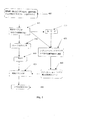
図2は、好ましい実施例によるビデオセグメントアナライザ140を示す。ブロック200では、解析のために、図1のビデオセグメンタ120からのビデオセグメント130の最初のフレームを選択する。フレームイベントアナライザ202は、以下に図6を参照して説明するように、選択されたフレームと、そのフレームに関する注目時間領域(ROI)とを受け取り、ラベル付きRAGを生成する。次に、生成されたRAGはブロック204で格納され、決定ブロック206では、ビデオセグメント130の終わりに達したか否かを判定する。ビデオの終わりに達していれば、すなわち、決定ブロック206で真(イエス)が戻れば、ブロック208でビデオセグメントの処理は終了する。これに対し、決定ブロック206が偽(ノー)を戻した場合には、ビデオセグメント130で次に解析すべきフレームを検索し、処理はフレームイベントアナライザ202に戻る。ビデオセグメント130の各フレームはリアルタイムで選択、解析されるのが好ましい。しかし、実際には、解析すべきフレームの選択はデジタルビデオ解釈システムを適用する用途によって決まる。例えば、デジタルビデオ解釈システムを具備する装置によっては、各フレームを解析するときにリアルタイムの実行が不可能な場合もあり、そのような場合には、解析に際してビデオセグメントの所定のフレームのみを選択することになる。
【0033】
図3Bは、図3Aに示す空間的に分割されたフレーム300の三次元RAG310の一例を示す。空間的に分割されたフレーム300はR1からR9とラベル付けされた9つの領域を含む。領域R1は空を含む。領域R2、R3及びR9は陸地を含み、領域R8は道路を含む。領域R4は家に似た構造であり、領域R5及びR6はその家の突き出た構造物である。図3Aにおいて奥行きを指示するために、線を幾分太くして領域の境界線を示している。特に、それぞれの境界線の太さはZ軸に沿った奥行きの前後関係を示す。RAG310は分割フレーム300中の領域R1からR9を結合する辺を示す。領域R1、R2、R3、R7、R8及びR9は、全て、RAG310においてほぼ同じ奥行き(実線の辺により指示する)に位置しているが、異なるX−Y位置にある。領域R1は一方では領域R2、R8、R9に順次結合しており、他方では、領域R3及びR7に結合している。又、領域R4は領域R2、R3、R7及びR8と辺でつながっているが、破線の辺で指示するように、異なる奥行きにある。最後に、領域R5及びR6は領域R4と辺を共有するが、点線の辺により指示される異なる、平行な奥行きにある。このように、破線と点線は異なるZ平面と交わる。
【0034】
5.フレームイベントアナライザ
図4及び図5を参照して、図2のフレームイベントアナライザ202の機能性を更に詳細に説明する。図4に示すフレームイベントアナライザのステップは1つのアプリケーションドメイン(例えば、屋外のシーン)を使用する。そのようなアプリケーションドメインは空、水、木の葉、草、道路、人間などのフレーム領域にラベル付けするための知識と機能性を含んでいることができるであろう。
【0035】
図4において、情報源(例えば、デジタルビデオ信号、デジタル音声信号など)ごとの現在フレームとROI400がそのROI400を使用する状況アナライザ410に提供される。状況アナライザ410に加えて、図2のフレームイベントアナライザ202はフレームセグメンタ450と、アプリケーションにおけるラベルの先験的確率を調整する調整ユニット430と、領域アナライザ470とを具備する。
【0036】
ROIにおいて利用できる状況情報400は状況アナライザ410により解析される。状況情報を供給する源は複数存在するので、状況アナライザ410は、通常、2つ以上の状況解析ユニットを含む。
【0037】
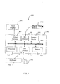
図7は、調整ユニット430及びアプリケーションドメイン440に関連して、状況アナライザ410を更に詳細に示す。図7に示す状況アナライザ410はフレームイベントに関わる状況情報400を受信する。この情報は音声ROI、動き解析ROI及び/又は赤外線スペクトルROIを含むのが好ましい。状況アナライザ410自体は、音声解析ユニット710と、動き解析ユニット720と、赤外線解析ユニット730とを含んでいても良い。状況アナライザ410により生成された出力は、調整ユニット430により、図4の領域アナライザ470により使用されるアプリケーションドメイン440におけるラベルの先験的確率を変更するために使用される。音声解析ユニット710は、音声信号ROIに入っているデジタル音声信号中のキーワード又はキーフレーズを認識し、次に、それらのキーワード/フレーズがそのフレームでは他のラベルと比べて特定のラベルが発生しやすいことを示唆しているか否かを検査することにより、この結果を得ても良い。他の状況アナライザユニット(例えば、720,730)は、ラベルの先験的確率を直接に変更しても良い。
【0038】
1つのアプリケーションドメイン440を伴うフレームイベントアナライザ210を有する好ましい実施例においては、アプリケーションドメイン440のラベルごとに、キーワード/キーフレーズごとの先験的確率重み付け係数と共に格納されているキーワード/キーフレーズ420のリストにもとづいて調整ユニット430によりラベルの先験的確率を調整しても良い。確率重み付け係数が大きくなるほど、そのラベルにより記述される領域がフレーム中に存在する尤度は高くなる。キーワード420に加えて、又はその代わりに、他の状況解析結果を調整ユニット430に提供しても良い。
【0039】
フレームセグメンタ450は、領域ベースセグメンテーション方法を使用して、フレームを複数の均質領域に分割する。通常、セグメンテーション方法は異なる情報源(例えば、ビデオ110A及び音声110B)のROIから抽出した状況情報を使用して、セグメンテーションプロセスを支援する。例えば、モーションベクトルによって、背景から動くオブジェクトを識別するのを助けることができる。焦点情報を利用できるのであれば、この情報を使用して距離を推定でき、従って、フレーム中の異なるオブジェクト又は領域平面を識別することができる。フレームセグメンタ450が実行するセグメンテーションプロセスの結果が図4に示すようなRAG460であり、RAG460は領域アナライザ470に入力として提供される。このRAGは三次元であるのが好ましい。領域アナライザ470に対するもう一方の入力は、状況情報に従ってラベルの先験的確率が調整されている場合もあるアプリケーションドメイン440である。
【0040】
確率モデルに基づいた領域アナライザ470は、RAG中の領域に適切なアプリケーションドメイン440を使用して最適のラベルを付ける。その結果として得られるラベル付きRAGは、内容に基づいた検索などのより高いレベルのプロセスに使用できるフレームの内容の記述、すなわち、メタデータを表現する。領域アナライザはMRF(確率)モデルを使用して、ラベル付きRAG480を生成するのが好ましい。MRFモデルについては、以下に詳細に説明する。
【0041】
図5には、フレームイベントアナライザが複数のアプリケーションドメインを有することを除いて、図4とほぼ同様に説明できるフレームイベントアナライザが示されている。複数のアプリケーションドメインを有するフレームイベントアナライザ(すなわち、図5に示すようなフレームイベントアナライザ)の場合、各アプリケーションドメインはキーワード/キーフレーズを含むと考えられ、選択ユニット530の役割として、解析で使用すべきアプリケーションドメインの選択を含めることができる。すなわち、選択ユニット530は最も確率の高いアプリケーションドメインを選択し、選択したドメインにおけるラベルの先験的確率を調整するのが好ましい。
【0042】
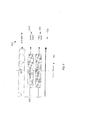
図6を参照すると、ビデオセグメントに関する時間系列が示されている。ビデオセグメントの現在フレーム601は、利用可能な状況情報603、音声情報604(信号)及びビデオ情報605(信号)から抽出した1つ又は複数の注目領域(ROI)602を参照して解析される。
【0043】
ROIの時間境界は、状況情報(図6を参照)の型に応じて変わることもある。例えば、カメラパラメータのような状況情報は長い時間周期、おそらくはビデオセグメント全体にわたって広がっている可能性がある。これに対し、ビデオ信号のROIははるかに短く、おそらくは現在解析中であるフレームの前後の数フレームにすぎないと考えられる。図6に示すように、ROIの中心は現在フレームにあるとは限らない。例えば、ROIが先行フレームを含むこともありうる。
【0044】
数学的には、RAGは互いに素な領域の集合R及びそれらの領域を結合する辺の集合E、すなわち、G={R,E}を含むグラフGであると定義される。ビデオフレーム解釈では、Gの中の領域に最適のラベルを付けようとする。アプリケーションドメインが状況情報の解析によって偏りの与えられた先験的確率PrL={PrL1,PrL2,PrL3,..,PrLp}を伴うp個のラベルの集合L={L1,L2,L3,..,Lp}から構成されているとすれば、解釈プロセスはグラフGにおいて最も確率の高いラベルの集合を推定するプロセスであるとみなすことができる。
【0045】
グラフGがN個の互いに素な領域から構成されるならば、X={X1,X2,X3,..,XN}をRAGにおける一連の確率変数とする。すなわち、Xは確率場であり、XiはRiと関連する確率変数である。Xiの実現xiはラベルの集合Lの一メンバである。Gにおける隣接系Гは次のように示される。
【0046】
【数1】
![]()
式中、n(Ri)はRiの隣接領域を含むRの部分集合である。領域Riの隣接系はその領域と、Riと共通する境界線を有する他の全ての領域とであるのが好ましい。
【0048】
更に、Ωはあり得る全てのラベル付け構成の集合であり、ωはΩの中の1つの構成を示す。
【0049】
【数2】
![]()
そこで、Xは、
P(X=ω)>0
なるXのあらゆる実現に対して、
【0051】
【数3】
![]()
であれば、隣接系Γに関してMRFである。
【0053】
MRFの重要な特徴は、その同時確率密度係数P(X=ω)がギブズの分布を有することである。すなわち、
【0054】
【数4】
![]()
式中、Tは温度であり、U(ω)はギブズのエネルギー関数である。分配関数Zは次のように求められる。
【0056】
【数5】

エネルギー関数は「クリーク」の概念を使用して表現できる。グラフGと関連するクリークcは、1つの領域か、又は、その全てが互いに隣接するいくつかの領域かのいずれかを含むようなRの部分集合である。図3Bに示すRAGの中の領域ごとのクリークを図8に示す。例えば、領域R1は関連するクリーク{R1}、{R1,R2}及び{R1,R3}を有する。
グラフGに関わるクリークの集合をCと呼ぶ。クリーク関数Vcは、(i∈c)であるxiの値(すなわち、ラベル)によってVc(ω)が決まるという特性を有する関数である。一群のクリーク関数はポテンシャルと呼ばれるので、Gに関するクリーク関数を加算することによりU(ω)を得ることができる。
【0058】
【数6】
![]()
フレーム及び先験的知識から得られる領域に基づく特徴測定値をクリーク関数Vcに取り入れる。領域特徴測定値の集合が与えられたときの特定の領域ラベルLiの尤度をトレーニングセット(例えば、神経ネットワーク)の使用を含めた様々な方法を使用して推定できる。あるいは、経験的知識に基づいて尤度を推定しても良い。同様に、測定値に基づく場合も、基づかない場合もあるという制約の形で、先験的知識をクリーク関数Vcに取り入れることも可能である。例えば、制約はラベルLiとラベルLjとが隣接できない(すなわち、隣接する確率が零である)という形態であっても良い。あるいは、LiとLjが隣接している場合、その境界はいくつかの特性(例えば、フラクタル次元)を有すると思われ、制約の値は測定値に従属しても良いであろう。
【0060】
式(4)から(6)は、構成に関わるギブズのU( )エネルギーを最小にすることは、その確率密度関数を最大にすることと等価であることを示す。本発明の好ましい実施例は、フレームから得られる測定値Mと、ラベルに関する先験的知識Kと、アプリケーションドメインにおけるラベルの先験的確率Prとが与えられた場合の最適の領域ラベル構成を見出そうとする。ラベルの先験的確率は、状況情報の解析によって偏りが与えられる。(フレームの)RAG全体にわたりラベルを最適化するという問題は、いずれかのサイトiでラベルを繰り返し最適化することにより解決できる。領域iにおけるラベルのM、K及びPrへの依存性を設計上のクリーク関数Vc(ω)に取り入れる。従って、サイトiにおけるXiをxiとするとき、条件付き確率密度関数を次のように書き表すことができる。
【0061】
【数7】
式中、CiはXiを含むクリークから構成されるCの部分集合であり、ωxはサイトiではxであり、その他の場所ではωと一致する構成を示す。ラベルの先験的確率を使用して、サイトの初期ラベルに偏りを与えることも可能である。例えば、先行する解析イベントのラベルを利用して、後の解析イベントのグラフを初期設定することができるであろう。
【0063】
先に述べた通り、クリーク関数はフレームからの特徴測定値M、ラベルに関する先験的知識K及びラベルの先験的確率Prに基づくことができる。例えば、アプリケーションドメインが屋外のシーンであるときのラベル「空(そら)」を考えてみると、RAGにおける領域(サイト)iを含むクリークの集合(すなわち、Ci)は、通常、その領域iのみから構成される単項クリークと、それぞれが領域iを含む領域群を包含するクリークの集合とから構成されると考えられるであろう。この場合、各領域はその領域群の領域に対して互いに隣接している。
【0064】
単項クリーク関数は、領域iに関する特徴の集合を測定し、次に、それらの特徴測定値を、手動操作で分割された画像からの空(そら)領域の例を使用して先にトレーニングされていた神経ネットワークへの入力として使用することにより、計算できるであろう。1つの領域に関して測定可能であると考えられる特徴の例は平均R、B、B値のいずれか1つ乃至3つと、平均輝度と、領域内の輝度の分散と、周波数ドメインで取り出される測定値を含む場合もあるテクスチャの特徴と、完全連続などの領域形状特徴とを含む。通常、神経ネットワークは、手動操作で分割された空(そら)領域の特徴測定値に類似する特徴測定値を有する領域に対しては低い値(例えば、零)を生成し、手動操作で分割された領域の特徴測定値に全く類似していない特徴測定値を有する領域に対しては高い値(例えば、1.0)を生成するようにトレーニングされるであろう。
【0065】
また、特徴測定値を2つ以上の領域を含むクリーク関数で使用することもできる。例えば、2つの領域の間の共通する境界のねじれを、一対の領域を含むクリーク関数で使用することが可能であろう。例えば、「空」と「水」との間の共通する境界は、通常、それほど大きなねじれを伴わないであろうが、「木の葉」と「空」との間の共通する境界は非常に大きなねじれを伴うであろう。
【0066】
制約の形態で、先験的知識をクリーク関数に取り入れることができる。例えば、「空」ラベルと、「草」ラベルとを含むクリーク関数は、「草」ラベルが適用されている領域が「空」ラベルが適用されている領域の上方にある場合は、高いエネルギー値(例えば、1.0)を戻すであろう。言い換えれば、「空」領域が通常はフレーム内で「草」領域の上方に位置しているという先験的知識を利用しているのである。
【0067】
「空」である領域iの先験的確率Prskyをクリーク関数に取り入れることも可能であろう。これを実行する方法の1つは、既存の単項クリーク関数と、
【0068】
【数8】
のような乗算係数とを乗算することであろう。式中、αは先験的確率のクリーク関数全体への寄与に重み付けする(0,1)の範囲の何らかのパラメータである。また、先験的確率を2つ以上の領域を含むクリーク関数に取り入れることも可能であろう。この場合、クリーク関数に対する乗算係数は、通常、クリーク関数の各々のラベルの先験的確率を含むであろう。
【0070】
式7は、あるサイトにおいて最も確率の高いラベルを選択することは、ラベルの先験的確率により重み付けされた、そのサイトのギブズのエネルギー関数U(ω)を最小にすることと等価であることを実証している。フレームの最適な領域ラベル構成は、グラフGのN個のサイトの各々を繰り返し見て、各サイトのラベルを更新することにより得られる。領域ラベルを更新する方法はいくつかある。ある領域に対して、ラベルの一様な分布から、又はMRFの条件付き確率分布のいずれかから新たなラベルを選択することができる(すなわち、ギブズのサンプラ、Geman and Geman,IEEE Trans.Pattern Analysis and Machine Intelligence, 6,721から741ページ(1984年)を参照)。より迅速な対応が望まれるのであれば、反復条件付きモード(J.BesagがJ.R.Statistical Soc.B, 48の259から302ページ(1986年)の中で説明している)方法を使用しても良い。この第2の方法の場合、RAGのサイトを繰り返し見直し、各サイトにおいて、領域のラベルを最大の条件付き確率分布を有するラベルとなるように更新する。更新するサイトを巡回する反復手続きは、擬似焼きなましスキーム(simulated annealing scheme)(温度を徐々に下げる)の中で実現することができる。更新する方法は、本発明のこの実施例に関しては重大ではない。重大であるのは、ギブズのエネルギーU(ω)の計算に先験的確率を取り入れたことである。
6.状況アナライザ
図4の状況アナライザ410はそれぞれの情報源(例えば、ビデオ信号110A及び音声信号110B)について現在フレームとROI400を取り出し、アプリケーションドメイン440におけるラベルの先験的確率をどのようにバイアスすべきかに関して情報を調整ユニット430に提供する。図5に示すような状況アナライザ410の機能については、図2のフレームイベントアナライザ202に関連して既に説明した。以下、音声信号ROIにおける様々なキーワード/キーフレーズの有無に基づいてアプリケーションドメイン440におけるラベルの先験的確率を調整する方法を更に詳細に説明する。その他の状況情報に対して類似の方法を使用することができる。
【0071】
各ラベルを1つ又は複数の根拠単位と関連付けることができ、1つの根拠単位はキーワード又はキーフレーズと、0から1までの重み係数とを含む。例えば、ラベル「水」の根拠単位はキーワード「ビーチ」と、重み付け係数0.8とから成ると考えても良いであろう。重み付け係数の値は、音声ROIにおけるキーワードの存在がRAG中の少なくとも1つの領域について「水」は適切なラベルであることを示す尤度を意味する。
【0072】
根拠を収集する前に、全てのラベルの先験的確率の和は1.0になるはずである。言い換えれば、
【0073】
【数9】
状況情報のROIから根拠を収集するとき、根拠単位を具体化する。所定のラベルlに関する異なる具体化根拠単位の重み係数を加算して、そのラベルの総根拠Elを生成することができる。
【0075】
そこで、アプリケーションドメイン440におけるラベルのPrl値を、
【0076】
【数10】
を使用して計算することができる。なお、式中、xの値は、
【0078】
【数11】
を解くことにより求められる。
【0080】
この結果として得られるPrl値はクリーク関数により直接使用することができる(例えば、式8を参照)。
【0081】
7. 本発明の他の実施例
図11は、本発明の他の実施例によるビデオセグメントアナライザ140を示す。この場合、ビデオセグメントアナライザ140はオブジェクトに基づくデジタルビデオ符号化システムと統合されている。ブロック250では、図1のビデオセグメンタ120により生成されたビデオセグメント130の第1のフレームをビデオセグメントアナライザ140にロードする。フレームイベントアナライザ252はロードされたフレームを受け取り、図2Aのフレームイベントアナライザ202について説明したように、関連ROIからの状況情報を使用してフレームを解析し、ラベル付きRAGを得る。次に、フレームイベントアナライザ252はラベル付きRAGを領域エンコーダ254へ出力し、領域エンコーダ254はRAGを符号化する。領域エンコーダ254は、RAGの領域の隣接度及び奥行き情報、意味ラベルを含めて、RAGの領域をビットストリームに符号化する。ブロック256では、ビデオセグメントの終わりに到達したか否かを判定するために、検査を実行する。検査ブロック256が真(イエス)を戻せば、ビデオセグメントの処理はブロック258で終了する。検査又は決定ブロック256が偽(ノー)を戻した場合には、ブロック260でビデオセグメントの次のフレームをロードする。
【0082】
動き検出器262はビデオセグメントにおける動きをフレームごとに検出する。動き検出器は、領域ごとに、先行フレームから検出される何らかの動きを検査する。動きモデル(例えば、領域のアフィン変換)により個々の領域の動きを記述できれば、ブロック266でモデルパラメータをビットストリームに符号化する。検出された動きを動きモデルにより記述できない場合には、フレームをフレームイベントアナライザ252により解析し、新たなRAGを生成し、領域エンコーダ254により符号化する。
【0083】
図11に示すビデオセグメントアナライザ140では、意味ラベルを符号化デジタルビデオ信号と統合するのが好ましい。ビデオセグメントアナライザがデジタルビデオ符号化システムと統合されていれば、分解能に左右されずに領域を別個に符号化しても良い。これにより、任意の所望の分解能でデジタルビデオ信号の単純な再構成が可能になる。デジタルビデオ信号を符号化する方法は、当業者に良く知られているそのようないくつかの技法のうちいずれかを使用して実行されれば良い。ビデオセグメントアナライザ140を必ずしもデジタルビデオ符号化システムと統合しなければならないとは限らないことは明らかである。先に述べた通り、統合するのではなく、ビデオセグメントアナライザ140はメタデータを生成するだけであっても良い。そのような実施例においては、1つのセグメントの全てのビデオフレームを処理する必要はないであろう。言い換えれば、1つのセグメントの中で選択されたフレームだけを解析すれば良いのである。そのようなフレームの選択の大部分は実現の態様によって決まるため、どのようにしてフレームを選択するかを指定することは、本発明の実施例の目的ではない。例えば、ビデオ解釈システムはリアルタイムに近い方式で動作する必要があるだろう。
【0084】
本発明の更に別の実施例は、ビデオフレームのセグメンテーションのプロセスと領域のラベル付けのプロセスとを1つの最小化プロセスに組み合わせたものである。
【図面の簡単な説明】
【図1】好ましい実施例によるデジタルビデオ解釈システムのブロック線図である。
【図2】好ましい実施例による図1のビデオセグメントアナライザを示す図である。
【図3A】
【図3B】本発明の実施例に従った代表的なセグメント分割画像と、対応する領域隣接度グラフ(RAG)とをそれぞれ示す図である。
【図4】1つのアプリケーションドメインを有する図2のフレームイベントアナライザを示す図である。
【図5】複数のアプリケーションドメインを有する図2の別のフレームイベントアナライザを示す図である。
【図6】特定の解析イベントに関する注目時間領域(ROI)の選択を示す図である。
【図7】図4又は図5のフレームイベントアナライザで使用するための好ましい状況アナライザを示す図である。
【図8】図3BのRAGと関連するクリークを示す図である。
【図9】本発明の実施例を実施しうるデジタルビデオ源と共に使用するための代表的なコンピュータのブロック線図である。
【図10】本発明の実施例を実施しうる代表的なデジタルビデオ源のブロック線図である。
【図11】オプションとしてデジタルビデオ符号化システムに統合されている、別の実施例による図1のビデオセグメントアナライザを示す図である。[0001]
BACKGROUND OF THE INVENTION
The present invention relates to statistical analysis of digital video signals, and more particularly to statistical analysis of digital video signals for automatic content interpretation with respect to semantic labels. Labels can then be used as the basis for tasks such as content-based searching and video abstract generation.
[0002]
[Prior art]
In general, digital video is assumed to be a signal representing the temporal development of a visual scene. Typically, this signal is encoded with associated audio information (eg, MPEG-2 audiovisual encoding format). In some cases, information about the scene or scene capture may be encoded along with the video and audio signals. Digital video is typically represented by a still digital image or a sequence of frames, where each digital image is composed of a set of pixel intensities for a plurality of color channels (eg, R, G, B). Most of this representation is based on a grid system in which visual scenes are perceived.
[0003]
The visual signal and the associated audio signal are correlated with each other in the sense that the content of the visual signal can be found in the audio signal and the content of the audio signal can be found in the visual signal. There are many cases. This correlation is evident in modern digital audiovisual coding formats, such as MPEG-4, where the encoding unit is an audiovisual object with limited spatial and temporal position in a scene. Is recognized. Such representations of audiovisual information are more adaptive to the use of digital material, but the visual components of natural scenes are still typically captured using grid-based sensing techniques ( That is, the digital image is sensed at a frame rate defined by the capture device). Thus, usually the process of digital video interpretation is still based on the process of digital image interpretation and is usually considered separately from the associated audio signal.
[0004]
Interpretation of digital image signals is the process of understanding the contents of an image and analyzing their spatial arrangement through the identification of meaningful objects or regions in the image. Traditionally, image interpretation tasks require human analysis. This is costly and time consuming, so much research has been done to build an automatic image interpretation system.
[0005]
Many existing image interpretation systems include low level processing and high level processing. Typically, low-level processing transforms an image from an array of pixel luminances into a set of spatially related image primitives such as edges and regions. Thereafter, various features can be extracted from the primitive (eg, average pixel brightness). High-level processing uses image domain knowledge and feature measurements to assign object labels or region labels, ie interpretations, to primitives, thereby building a description of “what is in the image” To do.
[0006]
Early image interpretation attempts were based on classifying individual primitives into a limited number of object classes according to their feature measurements. The success of this scheme has been limited by results that contain errors or incomplete results that frequently occur in low-level processing, and error in feature measurements due to noise in the image. Many modern techniques introduce spatial constraints on high-level processing. That is, an unclear region or object is often recognized as a result of successful recognition of an adjacent region or object.
[0007]
In addition, over time, techniques have emerged that model the spatial dependence of region labels on images using statistical methods such as Markov Random Fields (MRF). The main advantage of the MRF model is that it provides a general and natural model for the interaction of spatially related random variables, and an optimization algorithm that can be used to find the (global) optimal realization of the field. It is relatively flexible. Typically, MRF is defined in a graph of multiple regions divided into segments, commonly referred to as a region adjacency graph (RAG). The segmented regions can be generated by any one of the image segmentation methods based on the number of available regions. The MRF model constitutes a powerful mechanism that incorporates knowledge about the spatial dependence of the semantic labels as well as the dependence of the labels on the measurements (low-level features) from the image.
[0008]
Digital speech signal interpretation is the process of understanding the content of speech signals through the identification of words / phrases, or key speech, and analyzing their temporal arrangement. In general, digital speech analysis research concentrates on speech recognition because of the many possible applications of the resulting technology, such as natural language interfaces for computers and other electronic devices. It was.
[0009]
Hidden Markov models are widely used for continuous speech recognition because they inherently have the ability to incorporate sequential and statistical characteristics of digital speech signals. This model constitutes a probability framework for modeling time-varying processes in which speech units (phonemes, or possibly words) are represented as a sequence of time through a set of states. In order to estimate the probability of transition between states, it is necessary to analyze a set of sample speech signals for each speech unit (that is, a training set). If the recognition process must be independent of the speaker, the training set must contain sample speech signals from a range of speakers.
[0010]
SUMMARY OF THE INVENTION
According to one aspect of the invention, Contains information for determining depth An apparatus for interpreting a digital video signal having a plurality of types of situation information, the means for dividing the digital video signal into one or more video segments each having a corresponding portion of the plurality of types of situation information; A priori probabilities of application domain labels used in the region analyzer are changed according to an output obtained by analyzing the corresponding portions of the plurality of types of situation information by the situation analyzer, and are included in each video segment by the region analyzer Labeled for one or more areas Three-dimensional And an analysis means for forming an adjacency graph.
[0012]
According to yet another aspect of the invention, Contains information for determining depth A computer readable medium having recorded thereon a computer program for interpreting a digital video signal having a plurality of types of situation information, each of the digital video signals having a corresponding portion of the plurality of types of situation information Changing a priori probabilities of labels of application domains used in the region analyzer according to means for dividing into one or more video segments and the output of the corresponding portion of the plurality of types of situation information analyzed by the situation analyzer; Labeled with one or more regions contained in each video segment by the region analyzer Three-dimensional There is provided a computer-readable medium in which a computer program for causing a computer to function as analysis means for forming an adjacency graph is recorded.
[0013]
DETAILED DESCRIPTION OF THE INVENTION
Hereinafter, embodiments of the present invention will be described with reference to the accompanying drawings.
[0014]
1. Overview
The present invention relates to a method, apparatus and system for automatically generating an abbreviated high-level description of a digital video signal that captures (significant) semantic content of the digital video signal in the spatial and temporal domains. Such a description can later be used for a number of purposes including content-based searching, browsing video sequences or creating digital video abstracts.
[0015]
A digital video signal is understood to be a visual signal recorded by a video capture device. This signal is usually generated from a two-dimensional sensor array (eg, a CCD array) at a specified sampling rate, but this may not always be the case. Each sample is represented by one (video) frame. This analysis of the spatial and temporal content of the signal benefits from a range of situational information. In some cases, this status information is included in the digital video signal (e.g., motion), and other related sources (e.g., associated audio signals, recorded camera parameters, commonly used). In some cases, information may be available from other sensors than the sensor of the visual spectrum. The range of available situation information is much wider than that available in the still image analysis process and has the additional property of time evolution.
[0016]
The time evolution of the digital image signal in the video signal can be used to improve the results of the image interpretation process of the digital video signal. For example, motion information can be used to assist in the detection of a human-like object moving in a digitally recorded scene. It is also possible to selectively group multiple regions in an image frame as part of the scene background using motion. The process of interpreting or understanding a digital video signal will also benefit from the identification of audio elements (audio and non-audio) that are present in the associated audio signal. For example, it may be possible to assist the interpretation process with words identified in the audio signal. Also, audio signals associated with wildlife documentaries include sounds produced by various animals, which may help to identify the content of the video signal.
[0017]
Embodiments of the present invention extend the use of probabilistic models such as MRF to the interpretation of digital video signals. This iterates the probabilistic model throughout the video sequence to integrate information in the form of measurements and knowledge from different sources (e.g. video frames, audio signals, etc.) in a single optimization procedure. Including using.
[0018]
In an embodiment of the invention, a high-level description is generated at selected analysis events throughout the digital video signal. The high level description is based on the assignment of different semantic labels to the different areas that appear in the analysis event. At each analysis event, the video frame centered on the analysis event is automatically spatially divided into a plurality of homogeneous regions. These regions and their spatial adjacency characteristics are represented by a region adjacency graph (RAG). Therefore, the probability model is applied to RAG. The model includes feature measurements from the region of the frame, situational information from the region of interest (ROI) around the frame, and a priori knowledge of various semantic labels that may be associated with the region of the RAG. . Their semantic labels (e.g. `` people '', `` sky '', `` water '', `` leaves '' etc.) are typically for the appropriate application domain (e.g. outdoor scenes, weddings, urban scenes etc.) Retrieved from the constructed list.
[0019]
At each analysis event, the situation information is used to bias the a priori probability of the semantic label (hereinafter referred to as the label) of the appropriate application domain selected. The analysis executed at a predetermined analysis event also depends on the preceding analysis event. This dependency is usually greater when two analysis events are close to each other in the time domain. For example, in one video segment, although not necessarily so, the label selected for the region in the previous recent analysis event is the label that was not selected in the description of the current section of the digital video. It can be said that it has a higher probability.
[0020]
A digital video interpretation system can operate with one or more application domains. When using a plurality of application domains, the application domain with the highest probability can be determined using the situation information. The application domain can be either narrow (ie several labels) or wide (ie many labels can be used). Narrow application domains are usually considered to be used when very specific and reliable area labeling is required. For example, when applied to security, the ability to identify areas associated with humans and cars would be desirable, but the identification of those objects would be required with high reliability.
[0021]
In the following detailed description of the examples, numerous specific details, such as video encoding techniques, sensor types, etc., are set forth in order to provide a more thorough understanding of the description. However, it will be apparent to those skilled in the art that the present invention may be practiced without the specific details. In some cases, detailed descriptions of well-known features such as video formats, audio formats, etc., have been omitted so as not to obscure the present invention.
[0022]
2. Preferred embodiment digital video interpretation system
FIG. 1 illustrates a stochastic digital
[0023]
Digital
[0024]
The input to the digital
[0025]
In the digital
[0026]
The
[0027]
As illustrated by
[0028]
With reference to FIG. 9, a general purpose computer is coupled to a remote
[0029]
Alternatively, embodiments of the present invention may be implemented within a
[0030]
3. Video segmenter of preferred embodiment
[0031]
4). Preferred embodiment video segment analyzer
The
[0032]
FIG. 2 shows a
[0033]
FIG. 3B shows an example of a three-
[0034]
5). Frame event analyzer
The functionality of the
[0035]
In FIG. 4, the current frame and
[0036]
The
[0037]
FIG. 7 shows the
[0038]
In a preferred embodiment having a
[0039]
[0040]
A
[0041]
FIG. 5 shows a frame event analyzer that can be described in substantially the same manner as FIG. 4 except that the frame event analyzer has a plurality of application domains. In the case of a frame event analyzer having a plurality of application domains (ie, a frame event analyzer as shown in FIG. 5), each application domain is considered to contain a keyword / key phrase and is used in the analysis as the role of the
[0042]
Referring to FIG. 6, a time sequence for a video segment is shown. The
[0043]
The ROI time boundary may vary depending on the type of status information (see FIG. 6). For example, status information such as camera parameters may be spread over a long period of time, perhaps the entire video segment. In contrast, the ROI of the video signal is much shorter, probably only a few frames before and after the frame currently being analyzed. As shown in FIG. 6, the center of the ROI is not necessarily in the current frame. For example, the ROI may include a previous frame.
[0044]
Mathematically, RAG is defined to be a graph G including a set R of disjoint regions and a set E of edges connecting those regions, that is, G = {R, E}. In video frame interpretation, an optimum label is applied to the region in G. An a priori probability Pr in which the application domain is biased by analysis of situation information L = {Pr L1 , Pr L2 , Pr L3 ,. . , Pr Lp Set of p labels with} L = {L 1 , L 2 , L Three ,. . , L p }, The interpretation process can be regarded as a process for estimating a set of labels with the highest probability in the graph G.
[0045]
If the graph G is composed of N disjoint regions, X = {X 1 , X 2 , X Three ,. . , X N } Is a series of random variables in the RAG. That is, X is a random field and X i Is R i Is a random variable associated with. X i Realization of x i Is a member of a set L of labels. The adjacent system Γ in G is shown as follows.
[0046]
[Expression 1]
![]()
Where n (R i ) Is R i Is a subset of R including adjacent regions. Region R i The adjacent system of the region and R i And all other regions having a common boundary.
[0048]
Further, Ω is a set of all possible labeling configurations, and ω represents one configuration in Ω.
[0049]
[Expression 2]
![]()
So X is
P (X = ω)> 0
For every realization of X
[0051]
[Equation 3]
![]()
Then, it is MRF with respect to the adjacent system Γ.
[0053]
An important feature of MRF is that its joint probability density coefficient P (X = ω) has a Gibbs distribution. That is,
[0054]
[Expression 4]
![]()
Where T is the temperature and U (ω) is the Gibbs energy function. The partition function Z is obtained as follows.
[0056]
[Equation 5]
The energy function can be expressed using the concept of “creek”. The clique c associated with the graph G is a subset of R that includes either one region or several regions, all of which are adjacent to each other. A clique for each region in the RAG shown in FIG. 3B is shown in FIG. For example, region R1 has associated cliques {R1}, {R1, R2} and {R1, R3}.
A set of cliques related to the graph G is called C. Clique function V c Is (i∈c) x i V (by label) c This is a function having the characteristic that (ω) is determined. Since a group of clique functions is called a potential, U (ω) can be obtained by adding the clique functions for G.
[0058]
[Formula 6]
![]()
Clique function V is a feature measurement based on the frame and the region obtained from a priori knowledge. c Incorporate. A specific region label L given a set of region feature measurements i Can be estimated using various methods including the use of training sets (eg, neural networks). Alternatively, the likelihood may be estimated based on empirical knowledge. Similarly, a priori knowledge can be converted to clique function V in the form of constraints that may or may not be based on measurements. c It is also possible to incorporate it. For example, the constraint is label L i And label L j May not be adjacent to each other (that is, the probability of being adjacent is zero). Or L i And L j If they are adjacent, the boundary may have some characteristic (eg, fractal dimension), and the value of the constraint may be dependent on the measurement.
[0060]
Equations (4) through (6) show that minimizing Gibbs U () energy associated with the configuration is equivalent to maximizing its probability density function. The preferred embodiment of the present invention looks at an optimal region label configuration given a measurement M obtained from a frame, a priori knowledge K about the label, and a priori probability Pr of the label in the application domain. Try to put out. The a priori probability of the label is biased by analyzing the situation information. The problem of optimizing the label across the RAG (of the frame) can be solved by iteratively optimizing the label at any site i. Dependence of labels on M, K, and Pr in region i by design clique function V c Take in (ω). Therefore, X at site i i X i The conditional probability density function can be written as:
[0061]
[Expression 7]
Where C i Is X i Is a subset of C composed of cliques containing ω x Indicates a configuration that is x at site i and coincides with ω at other locations. It is also possible to bias the initial label of the site using the a priori probability of the label. For example, a graph of a subsequent analysis event could be initialized using the label of the previous analysis event.
[0063]
As mentioned above, the clique function can be based on feature measurements M from the frame, a priori knowledge K about the labels and a priori probability Pr of the labels. For example, consider the label “sky” when the application domain is an outdoor scene, and a set of cliques that include a region (site) i in RAG (ie, C i ) Will normally be considered to be composed of a single clique composed only of the region i and a set of cliques each including a region group including the region i. In this case, each region is adjacent to the region group.
[0064]
The unary clique function measures a set of features for region i, and then those feature measurements are previously trained using an example of an empty region from a manually segmented image. Could be calculated by using it as an input to a neural network. Examples of features that are considered measurable for a region are one to three of the average R, B, and B values, the average luminance, the luminance variance within the region, and the measured values taken in the frequency domain. Texture features that may include and region shape features such as complete continuity. Typically, a neural network generates a low value (eg, zero) for regions that have feature measurements that are similar to feature measurements of empty regions that have been manually segmented, and is segmented manually. For regions that have feature measurements that are not at all similar to the feature measurements of the selected region, they will be trained to produce a high value (eg, 1.0).
[0065]
Also, feature measurements can be used with clique functions that include more than one region. For example, a common boundary twist between two regions could be used in a clique function involving a pair of regions. For example, the common boundary between “sky” and “water” will usually not be accompanied by a very large twist, but the common boundary between “leaves” and “sky” is a very large twist. Will accompany.
[0066]
In the form of constraints, a priori knowledge can be incorporated into the clique function. For example, a clique function that includes an “empty” label and a “grass” label has a high energy value if the region where the “grass” label is applied is above the region where the “sky” label is applied. Will return (eg, 1.0). In other words, it uses a priori knowledge that the “empty” region is usually located above the “grass” region in the frame.
[0067]
A priori probability Pr of region i being “empty” sky Could be incorporated into the clique function. One way to do this is with an existing unary clique function,
[0068]
[Equation 8]
Would be multiplied by a multiplication factor such as Where α is some parameter in the range (0, 1) that weights the contribution of the a priori probability to the overall clique function. It would also be possible to incorporate a priori probabilities into clique functions that include more than one region. In this case, the multiplication factor for the clique function will typically include the a priori probability of each label of the clique function.
[0070]
Equation 7 shows that selecting the most probable label at a site is equivalent to minimizing the Gibbs energy function U (ω) for that site, weighted by the a priori probability of the label. Has been demonstrated. The optimal region label configuration of the frame is obtained by repeatedly looking at each of the N sites of the graph G and updating the label at each site. There are several ways to update region labels. For a region, a new label can be selected either from a uniform distribution of labels or from a conditional probability distribution of MRF (ie, Gibbs sampler, Geman and Geman, IEEE Trans. Pattern Analysis). and Machine Intelligence, 6, 721-741 (1984)). If a more rapid response is desired, use the iterative conditional mode method (described by J. Besag in JR Statistical Soc. B, 48, pages 259-302 (1986)). You may do it. In the case of the second method, the RAG sites are repeatedly reviewed, and the region labels are updated so as to have the maximum conditional probability distribution at each site. An iterative procedure that cycles through the sites to be updated can be realized in a simulated annealing scheme (gradually lowering the temperature). The updating method is not critical for this embodiment of the invention. Importantly, a priori probabilities have been incorporated into the calculation of Gibbs energy U (ω).
6). Situation analyzer
The situation analyzer 410 of FIG. 4 retrieves the current frame and
[0071]
Each label can be associated with one or more basis units, where one basis unit includes a keyword or key phrase and a weighting factor from 0 to 1. For example, the basis unit of the label “water” may be considered to be composed of the keyword “beach” and the weighting coefficient 0.8. The value of the weighting factor means a likelihood that the presence of a keyword in the voice ROI indicates that “water” is an appropriate label for at least one region in the RAG.
[0072]
Before collecting evidence, the sum of a priori probabilities for all labels should be 1.0. In other words,
[0073]
[Equation 9]
When collecting the basis from the ROI of the situation information, the basis unit is specified. Add the weighting factors of the different instantiation basis units for a given label l to get the total basis E for that label l Can be generated.
[0075]
Therefore, the Pr of the label in the
[0076]
[Expression 10]
Can be used to calculate. In the formula, the value of x is
[0078]
## EQU11 ##
Is obtained by solving
[0080]
The resulting Pr l The value can be used directly by the clique function (see, eg, Equation 8).
[0081]
7). Other embodiments of the invention
FIG. 11 illustrates a
[0082]
[0083]
In the
[0084]
Yet another embodiment of the present invention combines the process of video frame segmentation and region labeling into one minimization process.
[Brief description of the drawings]
FIG. 1 is a block diagram of a digital video interpretation system according to a preferred embodiment.
2 shows the video segment analyzer of FIG. 1 according to a preferred embodiment.
FIG. 3A
FIG. 3B is a diagram illustrating a representative segmented image and a corresponding region adjacency graph (RAG), respectively, according to an embodiment of the present invention.
4 shows the frame event analyzer of FIG. 2 with one application domain.
FIG. 5 shows another frame event analyzer of FIG. 2 having multiple application domains.
FIG. 6 is a diagram showing selection of a time-of-interest area (ROI) related to a specific analysis event.
7 shows a preferred situation analyzer for use with the frame event analyzer of FIG. 4 or FIG.
8 illustrates a clique associated with the RAG of FIG. 3B.
FIG. 9 is a block diagram of a representative computer for use with a digital video source that may implement embodiments of the present invention.
FIG. 10 is a block diagram of an exemplary digital video source that may implement embodiments of the present invention.
11 shows the video segment analyzer of FIG. 1 according to another embodiment, optionally integrated into a digital video encoding system.
Claims (2)
前記デジタルビデオ信号を、各々が前記複数種類の状況情報の対応する一部分を有する1つ又は複数のビデオセグメントに分割する手段と、
前記複数種類の状況情報の前記対応する部分を状況アナライザにより解析した出力に従って領域アナライザにおいて使用されるアプリケーションドメインのラベルの先験的確率を変更し、該領域アナライザによりそれぞれのビデオセグメントに含まれる1つ又は複数の領域に関わるラベル付き三次元隣接度グラフを形成する解析手段と
を具備する装置。An apparatus for interpreting a digital video signal having a plurality of types of situation information including information for determining depth ,
Means for dividing the digital video signal into one or more video segments each having a corresponding portion of the plurality of types of status information;
The a priori probability of the label of the application domain used in the region analyzer is changed according to the output obtained by analyzing the corresponding part of the plurality of types of situation information by the situation analyzer, and the region analyzer includes 1 And an analysis means for forming a labeled three-dimensional adjacency graph relating to one or more regions.
前記デジタルビデオ信号を、各々が前記複数種類の状況情報の対応する一部分を有する1つ又は複数のビデオセグメントに分割する手段と、
前記複数種類の状況情報の前記対応する部分を状況アナライザにより解析した出力に従って領域アナライザにおいて使用されるアプリケーションドメインのラベルの先験的確率を変更し、該領域アナライザによりそれぞれのビデオセグメントに含まれる1つ又は複数の領域に関わるラベル付き三次元隣接度グラフを形成する解析手段と
してコンピュータを機能させるコンピュータプログラムが記録されているコンピュータ読み取り可能媒体。A computer readable medium having recorded thereon a computer program for interpreting a digital video signal having a plurality of types of situation information including information for determining depth ,
Means for dividing the digital video signal into one or more video segments each having a corresponding portion of the plurality of types of status information;
The a priori probability of the label of the application domain used in the region analyzer is changed according to the output obtained by analyzing the corresponding part of the plurality of types of situation information by the situation analyzer, and is included in each video segment by the region analyzer. A computer-readable medium having recorded thereon a computer program that causes a computer to function as an analysis means for forming a labeled three-dimensional adjacency graph relating to one or a plurality of regions.
Applications Claiming Priority (2)
| Application Number | Priority Date | Filing Date | Title |
|---|---|---|---|
| AU3407 | 1985-11-13 | ||
| AUPP3407A AUPP340798A0 (en) | 1998-05-07 | 1998-05-07 | Automated video interpretation system |
Publications (3)
| Publication Number | Publication Date |
|---|---|
| JP2000030057A JP2000030057A (en) | 2000-01-28 |
| JP2000030057A5 JP2000030057A5 (en) | 2007-04-05 |
| JP4447689B2 true JP4447689B2 (en) | 2010-04-07 |
Family
ID=3807661
Family Applications (1)
| Application Number | Title | Priority Date | Filing Date |
|---|---|---|---|
| JP12772899A Expired - Fee Related JP4447689B2 (en) | 1998-05-07 | 1999-05-07 | Automatic video interpretation system |
Country Status (5)
| Country | Link |
|---|---|
| US (1) | US6516090B1 (en) |
| EP (1) | EP0955599B1 (en) |
| JP (1) | JP4447689B2 (en) |
| AU (1) | AUPP340798A0 (en) |
| DE (1) | DE69928164D1 (en) |
Families Citing this family (69)
| Publication number | Priority date | Publication date | Assignee | Title |
|---|---|---|---|---|
| US6792043B1 (en) * | 1998-10-23 | 2004-09-14 | Telecommunications Advancement Organization Of Japan | Method, apparatus and program products for retrieving moving image |
| JP4178629B2 (en) * | 1998-11-30 | 2008-11-12 | ソニー株式会社 | Information processing apparatus and method, and recording medium |
| AUPP764398A0 (en) * | 1998-12-11 | 1999-01-14 | Canon Kabushiki Kaisha | Method and apparatus for computing the similarity between images |
| US7107286B2 (en) * | 1999-07-26 | 2006-09-12 | Geoqwest International Inc. | Integrated information processing system for geospatial media |
| US6546135B1 (en) * | 1999-08-30 | 2003-04-08 | Mitsubishi Electric Research Laboratories, Inc | Method for representing and comparing multimedia content |
| US7383504B1 (en) * | 1999-08-30 | 2008-06-03 | Mitsubishi Electric Research Laboratories | Method for representing and comparing multimedia content according to rank |
| US7996878B1 (en) * | 1999-08-31 | 2011-08-09 | At&T Intellectual Property Ii, L.P. | System and method for generating coded video sequences from still media |
| US6795578B1 (en) * | 1999-09-29 | 2004-09-21 | Canon Kabushiki Kaisha | Image processing apparatus and method, and storage medium |
| US7035790B2 (en) * | 2000-06-02 | 2006-04-25 | Canon Kabushiki Kaisha | Speech processing system |
| US6954745B2 (en) * | 2000-06-02 | 2005-10-11 | Canon Kabushiki Kaisha | Signal processing system |
| US7072833B2 (en) * | 2000-06-02 | 2006-07-04 | Canon Kabushiki Kaisha | Speech processing system |
| US7010483B2 (en) * | 2000-06-02 | 2006-03-07 | Canon Kabushiki Kaisha | Speech processing system |
| US20020026253A1 (en) * | 2000-06-02 | 2002-02-28 | Rajan Jebu Jacob | Speech processing apparatus |
| US6813313B2 (en) * | 2000-07-06 | 2004-11-02 | Mitsubishi Electric Research Laboratories, Inc. | Method and system for high-level structure analysis and event detection in domain specific videos |
| US6763069B1 (en) * | 2000-07-06 | 2004-07-13 | Mitsubishi Electric Research Laboratories, Inc | Extraction of high-level features from low-level features of multimedia content |
| KR20020064794A (en) * | 2000-08-08 | 2002-08-09 | 코닌클리케 필립스 일렉트로닉스 엔.브이. | Using a secondary sensor for optimized video communications |
| US6810086B1 (en) | 2001-06-05 | 2004-10-26 | At&T Corp. | System and method of filtering noise |
| US7773670B1 (en) | 2001-06-05 | 2010-08-10 | At+T Intellectual Property Ii, L.P. | Method of content adaptive video encoding |
| US6970513B1 (en) * | 2001-06-05 | 2005-11-29 | At&T Corp. | System for content adaptive video decoding |
| US6909745B1 (en) | 2001-06-05 | 2005-06-21 | At&T Corp. | Content adaptive video encoder |
| US6968006B1 (en) * | 2001-06-05 | 2005-11-22 | At&T Corp. | Method of content adaptive video decoding |
| US20030140093A1 (en) * | 2002-01-23 | 2003-07-24 | Factor Cory L. | Method and apparatus for providing content over a distributed network |
| EP1488630B1 (en) * | 2002-03-14 | 2015-07-29 | UTC Fire & Security Americas Corporation, Inc. | High-speed search of recorded video information to detect motion |
| DE10224948A1 (en) * | 2002-06-05 | 2004-05-27 | Egner, Steffen, Dr. | Device and method for examining images |
| US7349477B2 (en) * | 2002-07-10 | 2008-03-25 | Mitsubishi Electric Research Laboratories, Inc. | Audio-assisted video segmentation and summarization |
| TWI238392B (en) * | 2002-09-02 | 2005-08-21 | Samsung Electronics Co Ltd | Optical information storage medium and method of and apparatus for recording and/or reproducing information on and/or from the optical information storage medium |
| US7116716B2 (en) | 2002-11-01 | 2006-10-03 | Microsoft Corporation | Systems and methods for generating a motion attention model |
| US8547437B2 (en) * | 2002-11-12 | 2013-10-01 | Sensormatic Electronics, LLC | Method and system for tracking and behavioral monitoring of multiple objects moving through multiple fields-of-view |
| US7221775B2 (en) * | 2002-11-12 | 2007-05-22 | Intellivid Corporation | Method and apparatus for computerized image background analysis |
| US7260261B2 (en) * | 2003-02-20 | 2007-08-21 | Microsoft Corporation | Systems and methods for enhanced image adaptation |
| US7454342B2 (en) * | 2003-03-19 | 2008-11-18 | Intel Corporation | Coupled hidden Markov model (CHMM) for continuous audiovisual speech recognition |
| US7286157B2 (en) * | 2003-09-11 | 2007-10-23 | Intellivid Corporation | Computerized method and apparatus for determining field-of-view relationships among multiple image sensors |
| US7280673B2 (en) * | 2003-10-10 | 2007-10-09 | Intellivid Corporation | System and method for searching for changes in surveillance video |
| US7346187B2 (en) * | 2003-10-10 | 2008-03-18 | Intellivid Corporation | Method of counting objects in a monitored environment and apparatus for the same |
| WO2005076594A1 (en) * | 2004-02-06 | 2005-08-18 | Agency For Science, Technology And Research | Automatic video event detection and indexing |
| US20050254546A1 (en) * | 2004-05-12 | 2005-11-17 | General Electric Company | System and method for segmenting crowded environments into individual objects |
| US9053754B2 (en) | 2004-07-28 | 2015-06-09 | Microsoft Technology Licensing, Llc | Thumbnail generation and presentation for recorded TV programs |
| US7986372B2 (en) * | 2004-08-02 | 2011-07-26 | Microsoft Corporation | Systems and methods for smart media content thumbnail extraction |
| US20060074980A1 (en) * | 2004-09-29 | 2006-04-06 | Sarkar Pte. Ltd. | System for semantically disambiguating text information |
| ATE500580T1 (en) | 2005-03-25 | 2011-03-15 | Sensormatic Electronics Llc | INTELLIGENT CAMERA SELECTION AND OBJECT TRACKING |
| US9036028B2 (en) | 2005-09-02 | 2015-05-19 | Sensormatic Electronics, LLC | Object tracking and alerts |
| KR20080075091A (en) * | 2005-09-12 | 2008-08-14 | 쓰리브이알 시큐리티, 인크. | Storage of video analysis data for real-time alerting and forensic analysis |
| US20070112811A1 (en) * | 2005-10-20 | 2007-05-17 | Microsoft Corporation | Architecture for scalable video coding applications |
| US8180826B2 (en) * | 2005-10-31 | 2012-05-15 | Microsoft Corporation | Media sharing and authoring on the web |
| US7773813B2 (en) * | 2005-10-31 | 2010-08-10 | Microsoft Corporation | Capture-intention detection for video content analysis |
| US8196032B2 (en) * | 2005-11-01 | 2012-06-05 | Microsoft Corporation | Template-based multimedia authoring and sharing |
| US7599918B2 (en) | 2005-12-29 | 2009-10-06 | Microsoft Corporation | Dynamic search with implicit user intention mining |
| US7825792B2 (en) * | 2006-06-02 | 2010-11-02 | Sensormatic Electronics Llc | Systems and methods for distributed monitoring of remote sites |
| US7671728B2 (en) * | 2006-06-02 | 2010-03-02 | Sensormatic Electronics, LLC | Systems and methods for distributed monitoring of remote sites |
| US7986842B2 (en) * | 2006-11-10 | 2011-07-26 | Fuji Xerox Co., Ltd. | Collective media annotation using undirected random field models |
| US8145673B2 (en) * | 2007-02-16 | 2012-03-27 | Microsoft Corporation | Easily queriable software repositories |
| JP5121258B2 (en) * | 2007-03-06 | 2013-01-16 | 株式会社東芝 | Suspicious behavior detection system and method |
| EP3438883B1 (en) * | 2007-06-04 | 2023-11-29 | Enswers Co., Ltd. | Method and apparatus for detecting a common section in moving pictures |
| CN101682750A (en) * | 2007-06-09 | 2010-03-24 | 传感电子公司 | System and method for integrating video analytics and data analytics/mining |
| US7996762B2 (en) * | 2007-09-21 | 2011-08-09 | Microsoft Corporation | Correlative multi-label image annotation |
| US9111146B2 (en) * | 2008-02-15 | 2015-08-18 | Tivo Inc. | Systems and methods for semantically classifying and normalizing shots in video |
| US8095963B2 (en) | 2008-04-30 | 2012-01-10 | Microsoft Corporation | Securing resource stores with claims-based security |
| WO2011080052A1 (en) | 2009-12-28 | 2011-07-07 | Thomson Licensing | Method for selection of a document shot using graphic paths and receiver implementing the method |
| US8489600B2 (en) * | 2010-02-23 | 2013-07-16 | Nokia Corporation | Method and apparatus for segmenting and summarizing media content |
| US8904517B2 (en) | 2011-06-28 | 2014-12-02 | International Business Machines Corporation | System and method for contexually interpreting image sequences |
| US9584806B2 (en) * | 2012-04-19 | 2017-02-28 | Futurewei Technologies, Inc. | Using depth information to assist motion compensation-based video coding |
| US10387729B2 (en) * | 2013-07-09 | 2019-08-20 | Outward, Inc. | Tagging virtualized content |
| KR102306538B1 (en) * | 2015-01-20 | 2021-09-29 | 삼성전자주식회사 | Apparatus and method for editing content |
| AU2015271975A1 (en) * | 2015-12-21 | 2017-07-06 | Canon Kabushiki Kaisha | An imaging system and method for classifying a concept type in video |
| WO2019110125A1 (en) * | 2017-12-08 | 2019-06-13 | Huawei Technologies Co., Ltd. | Polynomial fitting for motion compensation and luminance reconstruction in texture synthesis |
| US20220239831A1 (en) * | 2019-06-14 | 2022-07-28 | Sony Semiconductor Solutions Corporation | Transmission device, transmission method, reception device, reception method, and transmission-reception device |
| JP7296799B2 (en) | 2019-06-28 | 2023-06-23 | セコム株式会社 | Region dividing device, region dividing method, and region dividing program |
| US10930011B2 (en) * | 2019-07-02 | 2021-02-23 | Billups, Inc. | Digital image processing system for object location and facing |
| CN113438500B (en) | 2020-03-23 | 2023-03-24 | 阿里巴巴集团控股有限公司 | Video processing method and device, electronic equipment and computer storage medium |
Family Cites Families (15)
| Publication number | Priority date | Publication date | Assignee | Title |
|---|---|---|---|---|
| US3988715A (en) * | 1975-10-24 | 1976-10-26 | International Business Machines Corporation | Multi-channel recognition discriminator |
| US5467441A (en) * | 1993-07-21 | 1995-11-14 | Xerox Corporation | Method for operating on objects in a first image using an object-based model data structure to produce a second contextual image having added, replaced or deleted objects |
| US6181332B1 (en) * | 1993-10-28 | 2001-01-30 | International Business Machines Corporation | Method and system for contextual presentation of a temporal based object on a data processing system |
| US6211912B1 (en) * | 1994-02-04 | 2001-04-03 | Lucent Technologies Inc. | Method for detecting camera-motion induced scene changes |
| US5821945A (en) * | 1995-02-03 | 1998-10-13 | The Trustees Of Princeton University | Method and apparatus for video browsing based on content and structure |
| US5708767A (en) | 1995-02-03 | 1998-01-13 | The Trustees Of Princeton University | Method and apparatus for video browsing based on content and structure |
| JP3542428B2 (en) * | 1995-07-20 | 2004-07-14 | キヤノン株式会社 | Image forming apparatus and image display method |
| EP0805405A3 (en) * | 1996-02-05 | 1998-04-15 | Texas Instruments Incorporated | Motion event detection for video indexing |
| US6119135A (en) * | 1996-02-09 | 2000-09-12 | At&T Corporation | Method for passively browsing the internet using images extracted from web pages |
| US5870754A (en) * | 1996-04-25 | 1999-02-09 | Philips Electronics North America Corporation | Video retrieval of MPEG compressed sequences using DC and motion signatures |
| US6021213A (en) * | 1996-06-13 | 2000-02-01 | Eli Lilly And Company | Automatic contextual segmentation for imaging bones for osteoporosis therapies |
| KR100194923B1 (en) * | 1996-06-21 | 1999-06-15 | 윤종용 | Video information retrieval device and method |
| US5969716A (en) * | 1996-08-06 | 1999-10-19 | Interval Research Corporation | Time-based media processing system |
| US6137499A (en) * | 1997-03-07 | 2000-10-24 | Silicon Graphics, Inc. | Method, system, and computer program product for visualizing data using partial hierarchies |
| WO1999005865A1 (en) * | 1997-07-22 | 1999-02-04 | The Board Of Trustees Of The University Of Illinois | Content-based video access |
-
1998
- 1998-05-07 AU AUPP3407A patent/AUPP340798A0/en not_active Abandoned
-
1999
- 1999-04-22 EP EP99303123A patent/EP0955599B1/en not_active Expired - Lifetime
- 1999-04-22 DE DE69928164T patent/DE69928164D1/en not_active Expired - Lifetime
- 1999-04-23 US US09/296,612 patent/US6516090B1/en not_active Expired - Fee Related
- 1999-05-07 JP JP12772899A patent/JP4447689B2/en not_active Expired - Fee Related
Also Published As
| Publication number | Publication date |
|---|---|
| JP2000030057A (en) | 2000-01-28 |
| EP0955599A2 (en) | 1999-11-10 |
| AUPP340798A0 (en) | 1998-05-28 |
| DE69928164D1 (en) | 2005-12-15 |
| US6516090B1 (en) | 2003-02-04 |
| EP0955599B1 (en) | 2005-11-09 |
| EP0955599A3 (en) | 2000-02-23 |
Similar Documents
| Publication | Publication Date | Title |
|---|---|---|
| JP4447689B2 (en) | Automatic video interpretation system | |
| US7065250B1 (en) | Automated image interpretation and retrieval system | |
| US7224852B2 (en) | Video segmentation using statistical pixel modeling | |
| CN110651310B (en) | Deep learning method for estimating object density and/or flow, and related method and software | |
| Ravì et al. | Semantic segmentation of images exploiting DCT based features and random forest | |
| CN110717411A (en) | Pedestrian re-identification method based on deep layer feature fusion | |
| EP0913793A2 (en) | Image interpretation method and apparatus | |
| JP2010526455A (en) | Computer method and apparatus for processing image data | |
| JP2004505378A (en) | Context and content based information processing for multimedia segmentation and indexing | |
| JP2002125178A (en) | Media segmentation system and related method | |
| CN112528961B (en) | Video analysis method based on Jetson Nano | |
| JP2004350283A (en) | Method for segmenting compressed video into 3-dimensional objects | |
| CN112242002B (en) | Object identification and panoramic roaming method based on deep learning | |
| CN112068555A (en) | Voice control type mobile robot based on semantic SLAM method | |
| US20220391693A1 (en) | Training transformer neural networks to generate parameters of convolutional neural networks | |
| CN113901922A (en) | Hidden representation decoupling network-based occluded pedestrian re-identification method and system | |
| KR102230559B1 (en) | Method and Apparatus for Creating Labeling Model with Data Programming | |
| AU740614B2 (en) | Automated video interpretation system | |
| Kaur | Background subtraction in video surveillance | |
| AU735577B2 (en) | Automated image interpretation and retrieval system | |
| CN117152668B (en) | Intelligent logistics implementation method, device and equipment based on Internet of things | |
| CN117593702B (en) | Remote monitoring method, device, equipment and storage medium | |
| Chavan et al. | Multi object detection techniques in video surveillance application | |
| CN116778277B (en) | Cross-domain model training method based on progressive information decoupling | |
| JP7386006B2 (en) | Region division device, region division method, region division program, learning device, learning method, and learning program |
Legal Events
| Date | Code | Title | Description |
|---|---|---|---|
| A521 | Request for written amendment filed |
Free format text: JAPANESE INTERMEDIATE CODE: A523 Effective date: 20060508 |
|
| A621 | Written request for application examination |
Free format text: JAPANESE INTERMEDIATE CODE: A621 Effective date: 20060508 |
|
| RD01 | Notification of change of attorney |
Free format text: JAPANESE INTERMEDIATE CODE: A7426 Effective date: 20060508 |
|
| RD03 | Notification of appointment of power of attorney |
Free format text: JAPANESE INTERMEDIATE CODE: A7423 Effective date: 20060508 |
|
| RD04 | Notification of resignation of power of attorney |
Free format text: JAPANESE INTERMEDIATE CODE: A7424 Effective date: 20080729 |
|
| RD04 | Notification of resignation of power of attorney |
Free format text: JAPANESE INTERMEDIATE CODE: A7424 Effective date: 20080807 |
|
| A977 | Report on retrieval |
Free format text: JAPANESE INTERMEDIATE CODE: A971007 Effective date: 20090417 |
|
| A131 | Notification of reasons for refusal |
Free format text: JAPANESE INTERMEDIATE CODE: A131 Effective date: 20090424 |
|
| A521 | Request for written amendment filed |
Free format text: JAPANESE INTERMEDIATE CODE: A523 Effective date: 20090623 |
|
| A131 | Notification of reasons for refusal |
Free format text: JAPANESE INTERMEDIATE CODE: A131 Effective date: 20090717 |
|
| A521 | Request for written amendment filed |
Free format text: JAPANESE INTERMEDIATE CODE: A523 Effective date: 20090915 |
|
| A131 | Notification of reasons for refusal |
Free format text: JAPANESE INTERMEDIATE CODE: A131 Effective date: 20091016 |
|
| A521 | Request for written amendment filed |
Free format text: JAPANESE INTERMEDIATE CODE: A523 Effective date: 20091215 |
|
| TRDD | Decision of grant or rejection written | ||
| A01 | Written decision to grant a patent or to grant a registration (utility model) |
Free format text: JAPANESE INTERMEDIATE CODE: A01 Effective date: 20100115 |
|
| A01 | Written decision to grant a patent or to grant a registration (utility model) |
Free format text: JAPANESE INTERMEDIATE CODE: A01 |
|
| A61 | First payment of annual fees (during grant procedure) |
Free format text: JAPANESE INTERMEDIATE CODE: A61 Effective date: 20100121 |
|
| FPAY | Renewal fee payment (event date is renewal date of database) |
Free format text: PAYMENT UNTIL: 20130129 Year of fee payment: 3 |
|
| R150 | Certificate of patent or registration of utility model |
Free format text: JAPANESE INTERMEDIATE CODE: R150 |
|
| FPAY | Renewal fee payment (event date is renewal date of database) |
Free format text: PAYMENT UNTIL: 20140129 Year of fee payment: 4 |
|
| LAPS | Cancellation because of no payment of annual fees |