JP4445269B2 - Conveyor belt or chain without rod - Google Patents
Conveyor belt or chain without rod Download PDFInfo
- Publication number
- JP4445269B2 JP4445269B2 JP2003571180A JP2003571180A JP4445269B2 JP 4445269 B2 JP4445269 B2 JP 4445269B2 JP 2003571180 A JP2003571180 A JP 2003571180A JP 2003571180 A JP2003571180 A JP 2003571180A JP 4445269 B2 JP4445269 B2 JP 4445269B2
- Authority
- JP
- Japan
- Prior art keywords
- link
- section
- adjacent
- integral
- conveyor belt
- Prior art date
- Legal status (The legal status is an assumption and is not a legal conclusion. Google has not performed a legal analysis and makes no representation as to the accuracy of the status listed.)
- Expired - Fee Related
Links
Images


Classifications
-
- B—PERFORMING OPERATIONS; TRANSPORTING
- B65—CONVEYING; PACKING; STORING; HANDLING THIN OR FILAMENTARY MATERIAL
- B65G—TRANSPORT OR STORAGE DEVICES, e.g. CONVEYORS FOR LOADING OR TIPPING, SHOP CONVEYOR SYSTEMS OR PNEUMATIC TUBE CONVEYORS
- B65G17/00—Conveyors having an endless traction element, e.g. a chain, transmitting movement to a continuous or substantially-continuous load-carrying surface or to a series of individual load-carriers; Endless-chain conveyors in which the chains form the load-carrying surface
- B65G17/30—Details; Auxiliary devices
- B65G17/38—Chains or like traction elements; Connections between traction elements and load-carriers
- B65G17/40—Chains acting as load-carriers
-
- B—PERFORMING OPERATIONS; TRANSPORTING
- B65—CONVEYING; PACKING; STORING; HANDLING THIN OR FILAMENTARY MATERIAL
- B65G—TRANSPORT OR STORAGE DEVICES, e.g. CONVEYORS FOR LOADING OR TIPPING, SHOP CONVEYOR SYSTEMS OR PNEUMATIC TUBE CONVEYORS
- B65G17/00—Conveyors having an endless traction element, e.g. a chain, transmitting movement to a continuous or substantially-continuous load-carrying surface or to a series of individual load-carriers; Endless-chain conveyors in which the chains form the load-carrying surface
- B65G17/06—Conveyors having an endless traction element, e.g. a chain, transmitting movement to a continuous or substantially-continuous load-carrying surface or to a series of individual load-carriers; Endless-chain conveyors in which the chains form the load-carrying surface having a load-carrying surface formed by a series of interconnected, e.g. longitudinal, links, plates, or platforms
- B65G17/08—Conveyors having an endless traction element, e.g. a chain, transmitting movement to a continuous or substantially-continuous load-carrying surface or to a series of individual load-carriers; Endless-chain conveyors in which the chains form the load-carrying surface having a load-carrying surface formed by a series of interconnected, e.g. longitudinal, links, plates, or platforms the surface being formed by the traction element
Abstract
Description
本発明は、一般に、コンベヤ技術に関し、特に、「ロッドなし」コンベヤベルト又はチェーン又はその一部分又は1セクションを構成するためのモジュラーリンク又はリンクセクションに関する。 The present invention relates generally to conveyor technology, and more particularly to modular links or link sections for constructing "rodless" conveyor belts or chains or portions or sections thereof.
今日、多くの近代的生産設備において、モジュラーリンク式コンベヤシステム(以下、「モジュラーコンベヤシステム」又は「コンベヤシステム」又は単に「コンベヤ」とも称する)は、あらゆる生産段階においていろいろな作業ステーション間で物品を搬送するのに広く用いられている。近年、コンベヤを材料搬送処理システムの一体化された一部分として備えた生産ラインを用いる製造業者は、生産性及び資源利用率において相当に大きな利得を実現している。その結果として、モジュラーコンベヤシステムは、一層広汎に利用されるようになってきており、多種多様の消費財や産業用物品の製造業者の材料搬送処理面での更に広範囲の要望に対応するように改善されてきた。従って、この種のコンベヤのユーザーの要望や期待に応えるために改良モジュラーコンベヤの不断の開発が必要とされる。 Today, in many modern production facilities, modular link conveyor systems (hereinafter also referred to as “modular conveyor systems” or “conveyor systems” or simply “conveyors”) deliver goods between various work stations at every stage of production. Widely used for conveying. In recent years, manufacturers using production lines with conveyors as an integral part of material handling systems have realized significant gains in productivity and resource utilization. As a result, modular conveyor systems are becoming more widely used to meet a wider range of demands on the material handling process of a wide variety of consumer and industrial goods manufacturers. Has been improved. Therefore, the constant development of improved modular conveyors is required to meet the needs and expectations of users of this type of conveyor.
無端モジュラーリンク式又はローラ式ベルト又はチェーンを用いる慣用のコンベヤシステムは、通常、フレームによって地面上に支持されたレール等の細長ガイド構造体の一端で駆動される。駆動力は、可変速電気モータのような原動機から軸又はドラムのような回転駆動構造体に連結された複数の連結駆動スプロケットに伝達される。ガイド構造体の他端では、アイドラースプロケットが自由回転アイドラー軸又はドラムに連結される。駆動スプロケット及びアイドラースプロケットは、それぞれガイド構造体の各端で、無端ベルト又はチェーンが順方向(前進)走行路から戻り走行路へ、又、戻り走行路から順方向走行路へ移行する際に無端ベルト又はチェーンを支持し案内するのを助成する。端部駆動ユニットに代えて、又は、それに加えて、摩擦駆動手段を含む中間駆動ユニットを用いることもできる。 Conventional conveyor systems that use endless modular link or roller belts or chains are typically driven at one end of an elongated guide structure such as a rail supported on the ground by a frame. The driving force is transmitted from a prime mover such as a variable speed electric motor to a plurality of coupled drive sprockets coupled to a rotary drive structure such as a shaft or drum. At the other end of the guide structure, an idler sprocket is connected to a free rotating idler shaft or drum. The drive sprocket and idler sprocket are endless when the endless belt or chain moves from the forward (forward) travel path to the return travel path, or from the return travel path to the forward travel path, at each end of the guide structure. Help support and guide the belt or chain. Instead of or in addition to the end drive unit, an intermediate drive unit including friction drive means can be used.
この種のコンベヤに用いられるベルト又はチェーンは、多くの場合、側方に反復して設けられた複数のリンクで構成されるか、あるいは、側方に反復して設けられた複数のリンク形構造体(総称として「リンク」と称される)から成る一体的リンクセクションで構成される。これらのリンクは、通常、例えばアセタール又はUHMW(超高分子量)ポリプロピレンのような低コスト、高強度、耐摩性の材料で形成される。ベルトを形成するには、複数のリンク又はリンクセクションを互いに噛み合わせた、長手方向に反復する列として配置する。次いで、第1のリンク又はリンクセクションの第1部分、通常は先行部分に形成された1つ又は複数の孔と、次に隣接する第2のリンク又はリンクセクションの第2部分、通常は後行部分に形成された1つ又は複数の孔に通して突出させた横断方向のコネクタロッド(連結ロッド)によって各列を隣接する列に連結する。各列の両側側端には、横断コネクタロッドを所定位置に保持する耳片のような掛止構造体を受容するためのスロットが設けられている。この種のタイプのリンク及びそれらのリンクで構成されたベルト/チェーンは、本出願人の米国特許第4,953,693号及び5,031,757号に開示されており、それらの特許の記載内容が本明細書に編入されているものとする。このような態様に構成されたベルト又はチェーンは、低コストであること、融通性があること、耐用寿命が長いことなどから、材料搬送面での改善を求めるユーザーの間で広く受け容れられてきた。 The belt or chain used in this type of conveyor is often composed of a plurality of links repeatedly provided on the side or a plurality of link-type structures provided repeatedly on the side. Consists of an integral link section consisting of bodies (collectively referred to as “links”). These links are typically made of a low cost, high strength, wear resistant material such as acetal or UHMW (ultra high molecular weight) polypropylene. To form a belt, a plurality of links or link sections are arranged in a longitudinally repeating row that mesh with each other. Then one or more holes formed in the first part of the first link or link section, usually the preceding part, and then the second part of the next adjacent second link or link section, usually following Each row is connected to an adjacent row by a transverse connector rod (connecting rod) protruding through one or more holes formed in the part. Slots are provided at opposite ends of each row for receiving latching structures such as ear pieces that hold the transverse connector rods in place. Such types of links and belts / chains composed of those links are disclosed in Applicants' U.S. Pat. Nos. 4,953,693 and 5,031,757. The contents are incorporated herein. Belts or chains constructed in this manner have been widely accepted by users seeking improvements in material handling surfaces due to their low cost, flexibility, and long service life. It was.
一方、複数の相互に連結されたリンクで構成されており、しかも、織布のような連続した一体的材料で形成されているものとほとんど同じ様に動作することができるベルトの潜在的価値を認識し、そのようなベルトが、従来から提案されている。その一例は、米国特許第5,967,296号にみられる。この特許に開示されたベルトは、複数のリンクセクションで構成されており、各リンクセクションは、プラスチック製の横断コネクタロッドを受容するための孔を有する側方及び長手方向にずらされた球状ビードを備えている。横断コネクタロッドを1対の噛合したリンクセクションの互いに整列した孔に通した後、コネクタロッドの両端を溶融して隣接するリンクセクションの端部に叩きつけるなどの方法によってコネクタロッドの両端をかしめる。このようにしてかしめられたコネクタロッドの両端は、ベルトセクションを構成するために該ロッドをリンクセクション間の所定位置に保持する。 On the other hand, the potential value of a belt that is composed of a plurality of interconnected links and that can operate in much the same way as one that is formed of a continuous, monolithic material such as a woven fabric. Recognizing, such belts have been proposed in the past. An example is found in US Pat. No. 5,967,296. The belt disclosed in this patent consists of a plurality of link sections, each link section having laterally and longitudinally offset spherical beads with holes for receiving plastic transverse connector rods. I have. After passing the transverse connector rod through the aligned holes of a pair of mated link sections, both ends of the connector rod are crimped by a method such as melting both ends of the connector rod and hitting the ends of adjacent link sections. The ends of the connector rod thus crimped hold the rod in place between the link sections to form a belt section.
上記米国特許第5,967,296号に開示された慣用のモジュラーリンクコンベヤベルトよりは連続した一体材料で形成されたものに類似した動作をすることができるが、この方式には重大な欠点が存在する。第1の欠点は、ベルトを組み立てるのに法外な人時(延べ作業時間数)を必要とすることである。具体的にいえば、組み立て作業者は、2つのリンクセクションを互いに隣接させてそれらを噛合関係に整合させ、次いで、細いプラスチックロッドを2つの隣接したリンクセクションの整列した孔に通さなければならない。掛止耳片のようなものはないので、コネクタロッドを所定位置に確実に保持するためにはコネクタロッドの両端をかしめなければならない。ベルトを形成するには、この作業を何百回も繰り返さなければならず、製造時間、労力及び費用を増大させる大きな原因となる。又、かしめ作業が適正に行われなかったことなどにより横断コネクタロッドがたとえ1本でも正しく装着されていないとすると、時間が経つにつれてそのロッドが正しい位置から滑り出て、ベルト又はチェーンを完全に分解させてしまうこともある。もちろん、そのような故障があると、生産休止(ダウンタイム)を招くことになり、そのベルト又はチェーンの修理作業を終えるのに要する工数は、最初の組み立て作業と同様に時間がかかり、困難なものとなる。場合によっては、コネクタロッドのかしめられた端部は、リンクセクションがその隣接するリンクセクションに対して自由に枢動するのを阻止することもある。 Although the conventional modular link conveyor belt disclosed in U.S. Pat. No. 5,967,296 can operate more like that formed of a continuous, unitary material, this approach has significant drawbacks. Exists. The first drawback is that it requires extraordinary man-hours (total work hours) to assemble the belt. Specifically, the assembler must place the two link sections adjacent to each other and align them in mesh, and then pass a thin plastic rod through the aligned holes in the two adjacent link sections. Since there is no such thing as a hook ear piece, both ends of the connector rod must be crimped in order to securely hold the connector rod in place. This process must be repeated hundreds of times to form a belt, which is a major source of increased manufacturing time, labor and cost. Also, if even one of the transverse connector rods is not correctly installed due to the fact that the caulking work has not been performed properly, the rod will slide out of the correct position over time, and the belt or chain will be completely It may be decomposed. Of course, such a failure will result in production downtime, and the man-hours required to complete the repair work on the belt or chain will be as time-consuming and difficult as the initial assembly work. It will be a thing. In some cases, the crimped end of the connector rod may prevent the link section from pivoting freely relative to its adjacent link section.
又、横断コネクタロッドを不要にする、異なるタイプのコンベヤベルト又はチェーンも、従来から提案されている。例えば、米国特許第4,394,901号には、圧縮自在の「ロッドなし」ベルトが開示されている。このベルトでは、各リンクは、両側に対向した一体の突設短軸を備えており、それらの短軸が隣接するリンクに設けられたボックス形構造体に弛く受容されるようになされている。このタイプの構成は一般に特定の要件や目的には有効であるが、制約がないわけではない。例えば、この’901号特許に開示されたリンクは、「マイクロピッチ」(極小ピッチ)のベルトと又はチェーンを構成するためにスケールダウン(一定の比率での縮小)させるのには適していない。なぜなら、各リンクは、非常に小さいバージョン(例えば、高さ約6mm未満のリンク)で複製するには極めて困難な多くの特徴を有しているからである。更に、素材が軽量プラスチック材である場合、リンクを大幅に小型化したとすると、各リンクの両側から突出している一体の突設短軸のような構造体の強度が危うくなる。同特許に示されているベルトの高さ対ピッチ比も低く(例えば、5mm/27mm、即ち、約0.25)、従って、移行コンベヤの支持台の円弧状端部、ノーズバーのように小さい曲率半径を有する構造体に掛け渡すのには適し
ていない。
従って、比較的幅広の「ロッドなし」ベルトを形成するために別個の横断コネクタロッドを必要とすることなく相互に連結することができる改良されたモジュラーリンク又はリンクセクションを求める要望がある。そのようなモジュラーリンク又はリンクセクションがあれば、それらから得られるベルト又はチェーンの耐久性、強度及び態様寿命をほとんど損なうことなく、組み立て時間、労力及び費用を大幅に削減することができる。又、これらのリンク又はリンクセクションをプラスチック材で形成する場合、同じ材料で形成された一体のコネクタを用いれば、金属(ステンレス鋼)製の横断コネクタロッドを含む慣用のモジュラーリンクベルトに比べて、単位長さ当たりの重量を軽減することもできる。比較的幅広の搬送表面を創出するために、又、完全に平坦な上面部分を有するものを形成するためにこれらの複数のリンク又はリンクセクションからベルト又はチェーンを構成すれば、2つの隣接するコンベヤの端部の間に移行(受け渡し)組立体の一部として配置することができることも含めて、多くの異なるタイプの物品を受け取り、搬送することを可能にする。このベルト又はチェーンの駆動も、やはり、スプロケット又は摩擦駆動手段を用いて行うことができるので、融通性を高め、それに伴って、コンベヤシステムの設計者にとって利用可能なオプションを増やすことができる。又、コネクタロッドをなくしたことにより、このリンク又はリンクセクションを用いて「極小ピッチ」のベルト又はチェーンを形成するのを非常に容易にする。極小ピッチのベルト又はチェーンは、普通のコンベヤーにも、移行(受け渡し)コンベヤ等にも用いることができる。総じて、これらの能力を有する「ロッドなし」ベルト又はチェーンは、上述した従来技術のベルト又はチェーンのいろいろな問題点を解決し、制約に対処することよって長年抱かれてきた要望を充足することができる。 Accordingly, there is a need for an improved modular link or link section that can be interconnected without the need for separate transverse connector rods to form a relatively wide “rodless” belt. With such modular links or link sections, assembly time, labor and cost can be greatly reduced with little loss of durability, strength and aspect life of the belts or chains obtained therefrom. Also, when these links or link sections are formed of a plastic material, if an integral connector formed of the same material is used, compared to a conventional modular link belt including a transverse connector rod made of metal (stainless steel), The weight per unit length can also be reduced. Two adjacent conveyors can be constructed by constructing a belt or chain from these multiple links or link sections to create a relatively wide conveying surface and to form one having a perfectly flat top surface portion. Many different types of articles can be received and transported, including being able to be placed as part of a transition assembly between the ends of the. This belt or chain drive can again be done using sprockets or friction drive means, thus increasing flexibility and thus increasing the options available to the conveyor system designer. Also, the elimination of the connector rod makes it very easy to use this link or link section to form a “miniature pitch” belt or chain. A very small pitch belt or chain can be used for an ordinary conveyor, a transfer (delivery) conveyor or the like. In general, a “rodless” belt or chain having these capabilities can satisfy the long-standing needs of the prior art by solving various problems and addressing the limitations of the prior art belts or chains described above. it can.
本発明の第1側面によれば、物品又は製品を搬送するためのコンベヤベルトの一部分を形成するために隣接するリンク又はリンクセクションと結合して用いるためのモジュラーリンクセクションが提供される。このリンクセクションは、側方に反復して設けられた複数のリンク形部分を含む一体の本体から成る。各リンク形部分は、被搬送物品又は製品に係合することができる、又は、それらを支持するのを助成することができる表面と、1対の脚部分と、該脚部分の間に延設された少くとも1つの第1一体コネクタと、隣接するリンクの一部分をスナップ嵌め係合状態で受容することができる受容部を有する。このスナップ嵌め係合は、コンベヤベルトの一部分を形成するために各リンク又はリンクセクションと、隣接するリンク又はリンクセクションとの容易で、かつ、堅固な組み立てを可能にする。 According to a first aspect of the present invention, a modular link section is provided for use in conjunction with an adjacent link or link section to form a portion of a conveyor belt for conveying articles or products. The link section consists of a unitary body including a plurality of link-shaped portions that are repeatedly provided on the sides. Each link-shaped portion extends between and between a surface that can engage or assist to support the article or product to be conveyed, a pair of leg portions, and the leg portions. At least one first integrated connector and a receiving portion capable of receiving a portion of an adjacent link in a snap-fit engagement. This snap-fit engagement allows easy and robust assembly of each link or link section with adjacent links or link sections to form a portion of the conveyor belt.
一実施形態においては、前記受容部は、過大サイズの入口と、内方へ傾斜、又はテーパして頸部を構成する互いに対向した側壁を含む。使用においては、隣接するリンクの前記一部分を前記過大サイズの入口を通し、前記内方傾斜(テーパー)側壁に沿って前記頸部を弾発的に(スナップ)通過させて該受容部内に係止させ、それによって前記所望のスナップ嵌め係合を設定する。各リンク形部分の前記脚部分は、更に、外側側壁を有するものとすることができ、第1のリンク形部分の一方の脚部分の前記外側側壁と、それに隣接する第2のリンク形部分の一方の脚部分の前記外側側壁との間に第2一体コネクタを設けることができる。この第2一体コネクタは、ベルトを駆動又は案内するための駆動スプロケット又はアイドラースプロケットの1つの歯に係合するように構成される。 In one embodiment, the receptacle includes an oversized inlet and opposing side walls that slope or taper inward to form the neck. In use, the portion of the adjacent link passes through the oversized inlet and snaps through the neck along the inwardly tapered wall to snap into the receptacle. Thereby setting the desired snap-fit engagement. The leg portion of each link-shaped portion may further have an outer side wall, and the outer side wall of one leg portion of the first link-shaped portion and the second link-shaped portion adjacent thereto. A second integrated connector may be provided between the outer side wall of one leg portion. The second integral connector is configured to engage one tooth of a drive sprocket or idler sprocket for driving or guiding the belt.
本発明の第2側面によれば、物品又は製品を搬送するためのコンベヤベルトの一部分又は一セクションを形成するために隣接するリンクと結合して用いるための一体のモジュラーリンクが提供される。このリンクは、側方に反復して設けられた複数の尖端部分から成る。各尖端部分は、被搬送物品又は製品に係合することができる、又は、それらを支持するのを助成することができる表面を有し、1対の脚部分が、各尖端部分に突設され、該脚部分の間に少くとも1つの第1一体コネクタが配設される。各尖端部分は、隣接するリンクの一部分をスナップ嵌め係合状態で受容することができる受容部を有する。このスナップ嵌め係合は、コンベヤベルトの一部分又は一セクションを形成するために各リンクと隣接するリンクとの容易で、かつ、堅固な組み立てを可能にする。 According to a second aspect of the present invention, an integral modular link is provided for use in conjunction with adjacent links to form a portion or section of a conveyor belt for conveying articles or products. This link consists of a plurality of pointed portions that are repeatedly provided on the sides. Each pointed portion has a surface that can engage or assist in supporting the article or product to be conveyed, and a pair of leg portions project from each pointed portion. , At least one first integral connector is disposed between the leg portions. Each pointed portion has a receptacle that can receive a portion of an adjacent link in a snap-fit engagement. This snap-fit engagement allows easy and robust assembly of each link and adjacent links to form a portion or section of the conveyor belt.
一実施形態においては、各尖端部分の前記受容部は、過大サイズの入口と、内方へ傾斜、又はテーパして頸部を構成する互いに対向した側壁を含む。従って、隣接するリンクの前記一部分を前記過大サイズの入口を通し、前記内方傾斜側壁に沿って前記頸部を弾発的に(スナップ)通過させて該受容部内に係止させ、それによって前記所望のスナップ嵌め係合を設定する。各尖端部分の前記脚部分は、更に、外側側壁を有するものとすることができ、第1の尖端部分の一方の脚部分の前記外側側壁と、それに隣接する第2の尖端部分の一方の脚部分の前記外側側壁との間に第2一体コネクタを設けることができる。この第2一体コネクタは、ベルトを駆動又は案内するための駆動スプロケット又はアイドラースプロケットの1つの歯に係合するように構成される。 In one embodiment, the receiving portion of each pointed portion includes an oversized inlet and opposing side walls that slope or taper inward to form a neck. Accordingly, the portion of the adjacent link passes through the oversized inlet and snaps through the neck along the inwardly sloping side wall to lock into the receptacle, thereby Set the desired snap-fit engagement. The leg portion of each tip portion may further have an outer side wall, the outer side wall of one leg portion of the first tip portion and one leg of the second tip portion adjacent thereto. A second integral connector can be provided between the outer side wall of the portion. The second integral connector is configured to engage one tooth of a drive sprocket or idler sprocket for driving or guiding the belt.
特に好ましい実施形態においては、各尖端部は、各々垂直平面内でテーパした1対の外側側壁を有するものとする。更に、各脚部分は、該テーパーに対応する傾斜を有する内側側壁を有するものとする。従って、このように構成された2つのリンクが互いに連結されると、前記外側側壁と内側側壁とが、協同又は合致して、所定の角度の相対的枢動を可能にする。 In a particularly preferred embodiment, each tip has a pair of outer sidewalls each tapered in a vertical plane. Further, each leg portion has an inner side wall having an inclination corresponding to the taper. Thus, when two links configured in this way are connected to each other, the outer and inner sidewalls cooperate or match to allow relative pivoting at a predetermined angle.
本発明の第3側面によれば、物品又は製品を搬送するためのコンベヤベルトの一部分又は一セクションを形成するために隣接するリンクセクションと結合して用いるための一体のモジュラーリンクセクションが提供される。このリンクセクションは、被搬送物品又は製品に係合するように適合された、又は、それらを支持するのを助成するように適合された側方に反復して設けられた少くとも2つのリンク形部分から成る。第1及び第2脚部分が、各リンク形部分の一部分の構成し、第1脚部分と第2脚部分の間に少くとも1つの第1一体コネクタが延設される。第1のリンク形部分の一方の脚部分と、それに隣接する第2のリンク形部分の一方の脚部分との間に第2一体コネクタを設けられる。各リンク形部分は、更に、隣接するリンクセクションの一部分を受容し係止することができる受容部を有する。 According to a third aspect of the present invention, there is provided an integral modular link section for use in conjunction with an adjacent link section to form a portion or section of a conveyor belt for conveying articles or products. . This link section has at least two link shapes adapted to engage the articles to be transported or the product or repeatedly provided on the sides adapted to assist in supporting them. Consists of parts. The first and second leg portions constitute part of each link-shaped portion, and at least one first integrated connector extends between the first leg portion and the second leg portion. A second integral connector is provided between one leg portion of the first link-shaped portion and one leg portion of the second link-shaped portion adjacent thereto. Each link-shaped portion further has a receptacle that can receive and lock a portion of an adjacent link section.
一実施形態においては、前記第1及び第2一体コネクタは、円筒形であり、第2一体コネクタの方が第1一体コネクタより直径が大きい。いずれにしても、各第1一体コネクタは、隣接するリンク又はリンクセクションの受容部に受容されるように構成される。叉、各第2一体コネクタは、ベルトを駆動又は案内するための駆動スプロケット又はアイドラースプロケットの1つの歯に係合するように構成される。 In one embodiment, the first and second integrated connectors are cylindrical, and the diameter of the second integrated connector is larger than that of the first integrated connector. In any case, each first integral connector is configured to be received in a receiving portion of an adjacent link or link section. Additionally, each second integral connector is configured to engage one tooth of a drive sprocket or idler sprocket for driving or guiding the belt.
本発明の第4側面によれば、物品又は製品を搬送するための無端コンベヤベルトの一部分を形成するのに用いるためのモジュラーリンクコンベヤベルトセクションが提供される。このベルトセクションは、複数の一体リンクセクションから成る。各一体リンクセクションは、側方に反復して設けられた複数のリンク形部分を含み、各リンク形部分は、被搬送物品又は製品に係合するための、又は、それらを支持するのを助成するための表面と、1対の脚部分と、少くとも1つの第1一体コネクタを含む。リンクセクションのうちの第1のリンクセクションのリンク形部分は、隣接する第2のリンクセクションに対して枢動しうるような態様に、該第2のリンクセクションの第1一体コネクタをスナップ嵌め係合状態で受容するための受容部を有する。このスナップ嵌め係合は、コンベヤベルトセクションを形成するために第1のリンクセクションと隣接する第2のリンクセクションとの容易で、かつ、堅固な組み立てを可能にする。 According to a fourth aspect of the present invention, a modular link conveyor belt section is provided for use in forming a portion of an endless conveyor belt for conveying articles or products. This belt section consists of a plurality of integral link sections. Each integral link section includes a plurality of link-shaped portions that are repeatedly provided on the sides, each link-shaped portion for engaging with or supporting the article or product to be conveyed. And a pair of leg portions and at least one first integral connector. The link-shaped portion of the first link section of the link sections is snap-fit with the first integral connector of the second link section in such a manner that the link-shaped portion of the link section can be pivoted with respect to the adjacent second link section. It has a receiving part for receiving in the combined state. This snap-fit engagement allows easy and robust assembly of the first link section and the adjacent second link section to form a conveyor belt section.
一実施形態においては、第1のリンクセクションの前記第1一体コネクタは、隣接する第2のリンクセクションの1対の脚部分の間に突入し、第1のリンクセクションの各リンク形部分の前記受容部は、過大サイズの入口と、頸部を構成する内方へ傾斜又はテーパした対向側壁を含む。かくして、隣接する第2のリンクセクションの各第1一体コネクタを該過大サイズの入口を通し、内方傾斜側壁に沿って頸部を弾発的に通過させると、該コネクタは、該受容部内に係止され、それによって前記所望のスナップ嵌め係合を設定する。第1のリンクセクション及び第2のリンクセクションの一方又は両方の各リンク形部分の前記脚部分は、更に、外側側壁を有するものとすることができ、第1のリンク形部分の一方の脚部分の該外側側壁と、それに隣接する第2のリンク形部分の一方の脚部分の該外側側壁との間に第2一体コネクタを設けることができる。この第2一体コネクタは、ベルトを駆動又は案内するための駆動スプロケット又はアイドラースプロケットの1つの歯に係合するための表面を提供する。 In one embodiment, the first integral connector of the first link section protrudes between a pair of leg portions of adjacent second link sections, and the link-shaped portion of each link-shaped portion of the first link section. The receptacle includes an oversized inlet and opposing sidewalls that are inwardly inclined or tapered to define the neck. Thus, when each first integral connector of the adjacent second link section is passed through the oversized inlet and elastically passed through the neck along the inwardly sloping side wall, the connector is within the receptacle. Locked, thereby setting the desired snap-fit engagement. The leg portion of each link-shaped portion of one or both of the first link section and the second link section may further have an outer side wall, wherein one leg portion of the first link-shaped portion. A second integral connector may be provided between the outer side wall of the second link portion and the outer side wall of one leg portion of the second link-shaped portion adjacent thereto. This second integral connector provides a surface for engaging one tooth of a drive sprocket or idler sprocket for driving or guiding the belt.
特定的な実施形態においては、前記第1のリンクセクションの各リンク形部分は、1対の外側側壁を有する尖端部分を含み、各側壁は、垂直平面内でテーパーを有する。前記第2のリンクセクションの各脚部分は、外側側壁のテーパーに合致する傾斜を有する内側側壁を含む。かくして、互いに合致する外側側壁と内側側壁は、第1のリンクセクションと第2のリンクセクションとの間の一定限度の相対的枢動を容易にする。 In a particular embodiment, each link-shaped portion of the first link section includes a pointed portion having a pair of outer sidewalls, each sidewall having a taper in a vertical plane. Each leg portion of the second link section includes an inner sidewall having a slope that matches the taper of the outer sidewall. Thus, the mating outer and inner sidewalls facilitate a certain range of relative pivoting between the first link section and the second link section.
別の実施形態においては、第1のリンクセクション及び第2のリンクセクションの下面を特別な輪郭の表面又は湾曲表面とする。かくして、これらのリンクセクションが所定の角度だけ枢動されると、それらのリンクセクションの下面が、円筒形のノーズバー(鼻状バー)(以下、単に「ノーズ」とも称する)のような隣接するガイド構造体の輪郭に合致することができる。その結果として、このベルトセクションは、ガイド構造体に沿って円滑に走行することができる。 In another embodiment, the lower surfaces of the first link section and the second link section are special contoured surfaces or curved surfaces. Thus, when these link sections are pivoted by a predetermined angle, the lower surfaces of the link sections are adjacent guides such as cylindrical nose bars (hereinafter also referred to simply as “noses”). It can conform to the contour of the structure. As a result, the belt section can travel smoothly along the guide structure.
各リンク形部分は、更に、ほぼ円弧状又は丸み付きのノーズと、それに合致する凹部分を有する尖端部分を含むものとすることができる。2つの隣接するリンクセクションが連結されると、両者の相対枢動運動中、第1のリンクセクションの各尖端部分のノーズが、第2のリンクセクションの各尖端部分の凹部分と協同する。同様にして、各脚部分は、ほぼ円弧状又は丸み付きの先行凹部分と、それに合致する後行表面を有するものとすることができる。(ここで、「先行」とは、コンベヤの走行方向でみて先頭に立って移動するという意味であり、「後行」とは、コンベヤの走行方向でみて後からついていくという意味である。)使用において、互いに隣接するリンクセクションの相対枢動運動中、第1のリンクセクションの各脚部分の後行表面が、第2のリンクセクションの各脚部分の先行凹部分と協同する。 Each link-shaped portion may further include a pointed portion having a generally arcuate or rounded nose and a corresponding concavity. When two adjacent link sections are connected, the nose of each tip portion of the first link section cooperates with the recess of each tip portion of the second link section during their relative pivoting motion. Similarly, each leg portion may have a substantially arcuate or rounded leading recess and a trailing surface matching it. (Here, “preceding” means to move from the top in the traveling direction of the conveyor, and “following” means to follow later in the traveling direction of the conveyor.) In use, during the relative pivoting movement of adjacent link sections, the trailing surface of each leg portion of the first link section cooperates with the leading recess of each leg portion of the second link section.
本発明の第5側面によれば、物品又は製品を搬送することができ、ノーズバーのような比較的小さい直径のガイド構造体に沿って走行する無端コンベヤベルトの一部分を形成するのに用いるためのモジュラーリンクコンベヤベルトセクションが提供される。このベルトセクションは、複数のリンクセクションから成る。各リンクセクションは、側方に反復して設けられた複数のリンク形部分を含み、各リンク形部分は、被搬送物品又は製品に係合するための、又は、それらを支持するのを助成するための表面と、1対の脚部分と、一体コネクタを有する。リンクセクションのうちの第1のリンクセクションのリンク形部分は、隣接する第2のリンクセクションに対して枢動しうるような態様に、該隣接する第2のリンクセクションの一体コネクタを受容するための受容部を有する。第1のリンクセクション及びそれに隣接する第2のリンクセクションの下面は、これらのリンクセクションが所定量だけ枢動されると、それらのリンクセクションの下面が、ガイド構造体の輪郭に合致することができる湾曲輪郭を呈するように、特別な輪郭の表面又は湾曲表面とされる。その結果として、このベルトセクションは、ガイド構造体に沿って円滑に走行することができる。 According to a fifth aspect of the invention, an article or product can be transported and used to form part of an endless conveyor belt that travels along a relatively small diameter guide structure such as a nose bar. A modular link conveyor belt section is provided. The belt section is composed of a plurality of link sections. Each link section includes a plurality of link-shaped portions that are repeatedly provided on the sides, each link-shaped portion for engaging or supporting the article or product to be conveyed. And a pair of leg portions and an integral connector. The link-shaped portion of the first link section of the link sections receives the integral connector of the adjacent second link section in such a manner that it can pivot relative to the adjacent second link section. It has a receiving part. The lower surfaces of the first link section and the adjacent second link section may be such that when the link sections are pivoted by a predetermined amount, the lower surfaces of the link sections conform to the contour of the guide structure. A special contour surface or curved surface is used so as to exhibit a possible curved contour. As a result, the belt section can travel smoothly along the guide structure.
一実施形態においては、前記一体コネクタは、隣接する第2のリンクセクションの1対の脚部分の間に突入し、第1のリンクセクションの各リンク形部分の前記受容部は、過大サイズの入口と、頸部を構成する内方へ傾斜又はテーパした対向側壁を含む。かくして、隣接する第2のリンクセクションの各一体コネクタを、該過大サイズの入口を通し、内方傾斜側壁に沿って頸部を弾発的に通過させると、該コネクタは、該受容部内に係止され、それによって前記所望のスナップ嵌め係合を設定する。第1のリンクセクション及び第2のリンクセクションの一方又は両方の各リンク形部分の前記脚部分は、更に、外側側壁を有するものとすることができ、第1のリンク形部分の一方の脚部分の該外側側壁と、それに隣接する第2のリンク形部分の一方の脚部分の該外側側壁との間に第2一体コネクタを設けることができる。この第2一体コネクタは、ベルトを駆動又は案内するための駆動スプロケット又はアイドラースプロケットの1つの歯に係合するための表面を提供する。 In one embodiment, the integral connector projects between a pair of leg portions of adjacent second link sections, and the receptacle of each link-shaped portion of the first link section has an oversized inlet. And opposing side walls that are inclined or tapered inward to form the neck. Thus, as each integral connector of the adjacent second link section is elastically passed through the oversized inlet and along the inwardly sloping side wall, the connector engages within the receptacle. Is stopped, thereby setting the desired snap-fit engagement. The leg portion of each link-shaped portion of one or both of the first link section and the second link section may further have an outer side wall, wherein one leg portion of the first link-shaped portion. A second integral connector may be provided between the outer side wall of the second link portion and the outer side wall of one leg portion of the second link-shaped portion adjacent thereto. This second integral connector provides a surface for engaging one tooth of a drive sprocket or idler sprocket for driving or guiding the belt.
特定的な実施形態においては、各リンク形部分は、1対の外側側壁を有する尖端部分を含み、各側壁は、垂直平面内でテーパーを有する。第2のリンクセクションの各脚部分は、外側側壁のテーパーに合致する傾斜を有する内側側壁を含む。使用において、互いに合致する外側側壁と内側側壁は、第1のリンクセクションと第2のリンクセクションの間の一定角度範囲の相対的枢動を容易にする。 In a particular embodiment, each link-shaped portion includes a pointed portion having a pair of outer sidewalls, each sidewall having a taper in a vertical plane. Each leg portion of the second link section includes an inner sidewall having a slope that matches the taper of the outer sidewall. In use, the outer and inner sidewalls mating with each other facilitate relative pivoting of a range of angles between the first link section and the second link section.
別の実施形態においては、各リンク形部分は、ほぼ円弧状のノーズと、それに合致する凹部分を有する尖端部分を含むものとすることができる。2つの隣接するリンクセクションが相互に連結されると、両者の相対枢動運動中、第1のリンクセクションの各尖端部分のノーズが、第2のリンクセクションの各尖端部分の凹部分に近接して位置され、該凹部分に沿って移動する。同様にして、各脚部分は、ほぼ円弧状の先行凹部分と、それに合致する後行表面を有するものとすることができる。使用において、互いに隣接するリンクセクションの相対枢動運動中、第2のリンクセクションの各脚部分の円弧状先行凹部分が、第1のリンクセクションの各脚部分の後行表面に近接して位置され、該表面に沿って移動する。 In another embodiment, each link-shaped portion may include a pointed portion having a generally arcuate nose and a corresponding recess. When two adjacent link sections are connected to each other, during their relative pivotal movement, the nose of each pointed portion of the first link section is close to the recess of each pointed portion of the second link section. And move along the concave portion. Similarly, each leg portion may have a substantially arcuate leading recess and a trailing surface that matches it. In use, during relative pivoting movement of adjacent link sections, the arcuate leading recess of each leg portion of the second link section is positioned proximate to the trailing surface of each leg portion of the first link section. And move along the surface.
本発明の第6側面によれば、物品又は製品を搬送するためのコンベヤベルトの一部分を形成するために隣接するリンク又はリンクセクションと結合して用いるための一体モジュラーリンクセクションが提供される。このリンクセクションは、各々、被搬送物品又は製品に係合することができる、又は、それらを支持するのを助成することができる表面を有する側方に反復して設けられた複数のリンク形部分から成る。各リンク形部分の高さ対各リンク形部分の幅の比は、約3.75とする。互いに隣接するリンクセクションのスナップ嵌め係合は、コンベヤベルトの一部分を形成するために各リンクセクションと、隣接するリンク又はリンクセクションとの容易で、かつ、堅固な組み立てを可能にする。 According to a sixth aspect of the present invention, an integral modular link section is provided for use in conjunction with an adjacent link or link section to form a portion of a conveyor belt for conveying articles or products. The link sections each have a plurality of link-shaped portions that are repeatedly provided on the sides with surfaces that can engage or support the articles or products to be conveyed. Consists of. The ratio of the height of each link-shaped portion to the width of each link-shaped portion is about 3.75. The snap-fit engagement of adjacent link sections allows easy and robust assembly of each link section and adjacent links or link sections to form a portion of the conveyor belt.
本発明の第7側面によれば、物品又は製品を搬送するためのコンベヤベルトの一部分を形成するために隣接するリンク又はリンクセクションと結合して用いるための一体モジュラーリンクセクションが提供される。このリンクセクションは、各々、被搬送物品又は製品に係合することができる、又は、それらを支持するのを助成することができる表面を有する側方に反復して設けられた複数のリンク形部分から成る。各リンク形部分の高さ対各リンク形部分の幅の比は、約2.5とする。互いに隣接するリンクセクションのスナップ嵌め係合は、コンベヤベルトの一部分を形成するために各リンクセクションと、隣接するリンク又はリンクセクションとの容易で、かつ、堅固な組み立てを可能にする。 According to a seventh aspect of the present invention, an integral modular link section is provided for use in conjunction with an adjacent link or link section to form a portion of a conveyor belt for conveying articles or products. The link sections each have a plurality of link-shaped portions that are repeatedly provided on the sides with surfaces that can engage or support the articles or products to be conveyed. Consists of. The ratio of the height of each link-shaped portion to the width of each link-shaped portion is about 2.5. The snap-fit engagement of adjacent link sections allows easy and robust assembly of each link section and adjacent links or link sections to form a portion of the conveyor belt.
本発明の第8側面によれば、物品又は製品を搬送するためのコンベヤベルトの一部分を形成するために隣接する第1及び第2のリンクと結合して用いるための一体モジュラーリンクが提供される。このリンクは、隣接する第1のリンクをスナップ嵌め係合状態に受容するための受容部と、隣接する第2のリンクと結合するためのコネクタと、被搬送物品又は製品に係合することができる、又は、それらを支持するのを助成することができる表面とを有する側方に反復して設けられた少くとも1つのリンク形部分から成り、該リンク形部分の高さは、約6mm未満であり、該スナップ嵌め係合が、コンベヤベルトの一部分を形成するために各リンクセクションと、隣接するリンク又はリンクセクションとの容易で、かつ、堅固な組み立てを可能にする。 According to an eighth aspect of the present invention there is provided an integral modular link for use in conjunction with adjacent first and second links to form a portion of a conveyor belt for conveying articles or products. . The link may engage a receiving portion for receiving an adjacent first link in a snap-fit engagement, a connector for coupling to an adjacent second link, and an article or product to be conveyed. Consisting of at least one link-shaped portion that is repeatedly provided laterally with a surface that can or can support them, the height of the link-shaped portion being less than about 6 mm The snap-fit engagement allows easy and robust assembly of each link section and adjacent links or link sections to form a portion of the conveyor belt.
一実施形態においては、リンク形部分の高さを4mmとし、各リンク形部分の幅を15mmとする。4つ又は8つの側方に反復して設けられたリンク形部分を設けることができる。これによって、周知のれんが積み技術を用いて複数のリンクセクションから成るベルト又はチェーンを容易に形成することができる。 In one embodiment, the height of the link-shaped portions is 4 mm and the width of each link-shaped portion is 15 mm. It is possible to provide link-shaped parts which are provided repeatedly on four or eight sides. This makes it possible to easily form a belt or chain consisting of a plurality of link sections using known brick stacking techniques.
本発明の第9側面によれば、物品又は製品を搬送するためのコンベヤベルトの一部分を形成するために隣接するリンク又はリンクセクションと結合して用いるための一体モジュラーリンクセクションが提供される。このリンクセクションは、各々、被搬送物品又は製品に係合することができる、又は、それらを支持するのを助成することができる表面と、1対の脚部分と、該脚部分の間に延設された少くとも1つの第1一体コネクタと、隣接するリンクの一部分をスナップ嵌め係合状態で受容することができる受容部とを有する側方に反復して設けられた複数のリンク形部分から成る。第2一体コネクタが、互いに隣接するリンク形部分の脚部分の間に延在して物品支持表面の一部分を画定し、それによって、実質的に連続した切れ目のない物品支持表面が得られる。 According to a ninth aspect of the present invention, an integral modular link section is provided for use in conjunction with an adjacent link or link section to form a portion of a conveyor belt for conveying articles or products. The link sections each have a surface that can engage or assist in supporting the article or product to be conveyed, a pair of leg portions, and extending between the leg portions. A plurality of link-shaped portions provided repeatedly on the side having at least one first integral connector provided and a receiving portion capable of receiving a portion of an adjacent link in a snap-fit engagement; Become. A second integral connector extends between the leg portions of adjacent link-shaped portions to define a portion of the article support surface, thereby providing a substantially continuous, unbroken article support surface.
本発明の第10側面によれば、物品又は製品を搬送することができる無端コンベヤベルトの一部分を形成するのに用いるための一体モジュラーリンクコンベヤベルトセクションが提供される。このベルトセクションは、複数のリンクセクションから成り、各リンクセクションは、被搬送物品又は製品に係合するための、又は、それらを支持するのを助成するための表面と、1対の脚部分と、一体コネクタを有する側方に反復して設けられた複数のリンク形部分を含む。リンクセクションのうちの第1のリンクセクションの各リンク形部分は、隣接する第2のリンクセクションに対して枢動しうるような態様に、第2のリンクセクションの一体コネクタを受容するための受容部を含む。各リンク形セクションの少くとも一部分は、高摩擦性搬送表面を有する。そのような高摩擦性搬送表面は、リンク形部分と一体に形成することが好ましい。 According to a tenth aspect of the present invention, an integral modular link conveyor belt section is provided for use in forming a portion of an endless conveyor belt capable of conveying articles or products. The belt section is comprised of a plurality of link sections, each link section having a surface for engaging or supporting the article or product to be conveyed, a pair of leg portions, , Including a plurality of link-shaped portions that are repeatedly provided laterally with integral connectors. Receiving for receiving the integral connector of the second link section in such a manner that each link-shaped portion of the first link section of the link sections can pivot relative to the adjacent second link section. Part. At least a portion of each linked section has a highly frictional conveying surface. Such a highly frictional conveying surface is preferably formed integrally with the link-shaped part.
本発明の第11側面によれば、物品又は製品を搬送することができる無端コンベヤベルトの一部分を形成するのに用いるための一体モジュラーリンクコンベヤベルトセクションが提供される。このベルトセクションは、複数のリンクセクションから成り、各リンクセクションは、側方に反復して設けられた複数のリンク形部分を含む。各リンク形部分は、被搬送物品又は製品に係合するための、又は、それらを支持するのを助成するための表面と、1対の脚部分と、少くとも1つの第1一体コネクタを有する。リンクセクションのうちの第1のリンクセクションの各リンク形部分は、隣接する第2のリンクセクションに対して枢動しうるような態様に、該第2のリンクセクションの第1一体コネクタを受容するための受容部を含む。第1のリンク形部分の一方の脚部分と、隣接する第2のリンク形部分の脚部分との間に第2一体コネクタが設けられる。この第2一体コネクタは、搬送表面の一部分を画定し、それによって複数個のリンクセクションが連結されたとき、実質的に切れ目のない、フラットトップの(頂面が平坦な)搬送表面が得られる。 According to an eleventh aspect of the present invention, an integral modular link conveyor belt section is provided for use in forming a portion of an endless conveyor belt capable of conveying articles or products. The belt section is composed of a plurality of link sections, and each link section includes a plurality of link-shaped portions repeatedly provided on the side. Each link-shaped portion has a surface for engaging or supporting the article or product to be transported, a pair of leg portions, and at least one first integral connector. . Each link-shaped portion of the first link section of the link sections receives the first integral connector of the second link section in such a manner that it can pivot relative to the adjacent second link section. Including a receiving portion. A second integral connector is provided between one leg portion of the first link-shaped portion and the leg portion of the adjacent second link-shaped portion. This second integral connector defines a portion of the transport surface, thereby providing a substantially unbroken, flat top (top surface) transport surface when a plurality of link sections are connected. .
本発明の第12側面によれば、物品又は製品を搬送するためのコンベヤベルトの一部分を形成するために隣接するリンク又はリンクセクションと結合して用いるための一体モジュラーリンクセクションが提供される。このリンクセクションは、各々、被搬送物品又は製品に係合することができる、又は、それらを支持するのを助成することができる表面と、1対の脚部分と、該脚部分の間に延設された少くとも1つの第1一体コネクタと、隣接するリンクセクションの一部分をスナップ嵌め係合状態で受容することができる受容部とを有する側方に反復して設けられた複数のリンク形部分から成る。第2一体コネクタが、互いに隣接するリンク形部分の脚部分の間に延在して物品支持表面の連続した一部分を画定する。更に、各リンク形部分の物品支持表面は、凸面とされ、あるいは、所定度の曲率を有する曲面に形成される。 According to a twelfth aspect of the present invention, an integral modular link section is provided for use in conjunction with an adjacent link or link section to form a portion of a conveyor belt for conveying articles or products. The link sections each have a surface that can engage or assist in supporting the article or product to be conveyed, a pair of leg portions, and extending between the leg portions. A plurality of link-shaped portions repeatedly provided on the side having at least one first integral connector provided and a receiving portion capable of receiving a portion of an adjacent link section in a snap-fit engagement. Consists of. A second integral connector extends between the leg portions of adjacent link-shaped portions to define a continuous portion of the article support surface. Furthermore, the article support surface of each link-shaped portion is formed as a convex surface or a curved surface having a predetermined degree of curvature.
本発明の第13側面によれば、物品又は製品を搬送することができる無端コンベヤベルトの一部分を形成するのに用いるための一体モジュラーリンクコンベヤベルトセクションが提供される。このベルトセクションは、複数のリンクセクションから成り、各リンクセクションは、側方に反復して設けられた複数のリンク形部分を含む。各リンク形部分は、被搬送物品又は製品に係合するための、又は、それらを支持するのを助成するための表面と、1対の脚部分と、一体コネクタを有する。リンクセクションのうちの第1のリンクセクションの各リンク形部分は、隣接する第2のリンクセクションに対して枢動しうるような態様に、第2のリンクセクションの一体コネクタを受容するための受容部を含む。各リンク形部分の物品支持表面は、断面でみてほぼ凸面状である。 According to a thirteenth aspect of the present invention, there is provided an integral modular link conveyor belt section for use in forming a portion of an endless conveyor belt capable of conveying articles or products. The belt section is composed of a plurality of link sections, and each link section includes a plurality of link-shaped portions repeatedly provided on the side. Each link-shaped portion has a surface for engaging or supporting the article or product to be conveyed, a pair of leg portions, and an integral connector. Receiving for receiving the integral connector of the second link section in such a manner that each link-shaped portion of the first link section of the link sections can pivot relative to the adjacent second link section. Part. The article support surface of each link-shaped portion is substantially convex when viewed in cross section.
本発明の第14側面によれば、物品又は製品を搬送するためのコンベヤベルトの一部分を形成するために隣接するリンク又はリンクセクションと結合して用いるための一体モジュラーリンクセクションが提供される。このリンクセクションは、各々、被搬送物品又は製品に係合することができる、又は、それらを支持するのを助成することができる表面と、1対の脚部分と、該脚部分の間に延設された少くとも1つの第1一体コネクタと、隣接するリンクの一部分をスナップ嵌め係合状態で受容することができる受容部とを有する側方に反復して設けられた複数のリンク形部分から成る。第2一体コネクタが、互いに隣接するリンク形部分の脚部分の間に延在して物品支持表面の物品支持表面の一部分を画定する。更に、各リンク形部分の物品支持表面は、少くとも1つの直立したクリート(突起又は桟)を有する。 According to a fourteenth aspect of the present invention, an integral modular link section is provided for use in conjunction with adjacent links or link sections to form a portion of a conveyor belt for conveying articles or products. The link sections each have a surface that can engage or assist in supporting the article or product to be conveyed, a pair of leg portions, and extending between the leg portions. A plurality of link-shaped portions provided repeatedly on the side having at least one first integral connector provided and a receiving portion capable of receiving a portion of an adjacent link in a snap-fit engagement; Become. A second integral connector extends between the leg portions of adjacent link-shaped portions to define a portion of the article support surface of the article support surface. Furthermore, the article support surface of each link-shaped portion has at least one upstanding cleat (projection or bar).
本発明の第15側面によれば、物品又は製品を搬送することができる無端コンベヤベルトの一部分を形成するのに用いるための一体モジュラーリンクコンベヤベルトセクションが提供される。このベルトセクションは、複数のリンクセクションから成り、各リンクセクションは、側方に反復して設けられた複数のリンク形部分を含む。各リンク形部分は、被搬送物品又は製品に係合するための、又は、それらを支持するのを助成するための表面と、1対の脚部分と、一体コネクタを有する。リンクセクションのうちの第1のリンクセクションの各リンク形部分は、隣接する第2のリンクセクションに対して枢動しうるような態様に、第2のリンクセクションの一体コネクタを受容するための受容部を含む。各リンク形部分は、更に、ほぼ直立したクリートを有する。 According to a fifteenth aspect of the present invention, an integral modular link conveyor belt section is provided for use in forming a portion of an endless conveyor belt capable of conveying articles or products. The belt section is composed of a plurality of link sections, and each link section includes a plurality of link-shaped portions repeatedly provided on the side. Each link-shaped portion has a surface for engaging or supporting the article or product to be conveyed, a pair of leg portions, and an integral connector. Receiving for receiving the integral connector of the second link section in such a manner that each link-shaped portion of the first link section of the link sections can pivot relative to the adjacent second link section. Part. Each link-shaped portion further has a substantially upright cleat.
本発明の第16側面によれば、物品又は製品を搬送するためのコンベヤベルトの一部分を形成するために隣接するリンク又はリンクセクションと結合して用いるための一体モジュラーリンクセクションが提供される。このリンクセクションは、各々、被搬送物品又は製品に係合することができる、又は、それらを支持するのを助成することができる表面と、1対の脚部分と、該脚部分の間に延設された少くとも1つの第1一体コネクタと、隣接するリンクセクションの一部分をスナップ嵌め係合状態で受容することができる受容部と、1対の直立した突片とを有する側方に反復して設けられた複数のリンク形部分から成る。第2一体コネクタが、互いに隣接するリンク形部分の脚部分の間に延在して物品支持表面の物品支持表面の一部分を画定する。 According to a sixteenth aspect of the present invention, an integral modular link section is provided for use in conjunction with an adjacent link or link section to form a portion of a conveyor belt for conveying articles or products. The link sections each have a surface that can engage or assist in supporting the article or product to be conveyed, a pair of leg portions, and extending between the leg portions. A laterally repeating portion having at least one first integral connector provided, a receiving portion capable of receiving a portion of an adjacent link section in a snap-fit engagement, and a pair of upstanding protrusions; A plurality of link-shaped portions provided. A second integral connector extends between the leg portions of adjacent link-shaped portions to define a portion of the article support surface of the article support surface.
本発明の第17側面によれば、物品又は製品を搬送することができる無端コンベヤベルトの一部分を形成するのに用いるための一体モジュラーリンクコンベヤベルトセクションが提供される。このベルトセクションは、複数のリンクセクションから成り、各リンクセクションは、側方に反復して設けられた複数のリンク形部分を含む。各リンク形部分は、被搬送物品又は製品に係合するための、又は、それらを支持するのを助成するための表面と、1対の脚部分と、一体コネクタと、1対の直立した突片を有する。リンクセクションのうちの第1のリンクセクションの各リンク形部分は、隣接する第2のリンクセクションに対して枢動しうるような態様に、第2のリンクセクションの一体コネクタを受容するための受容部を含む。 According to a seventeenth aspect of the present invention, there is provided an integral modular link conveyor belt section for use in forming a portion of an endless conveyor belt capable of conveying articles or products. The belt section is composed of a plurality of link sections, and each link section includes a plurality of link-shaped portions repeatedly provided on the side. Each link-shaped portion includes a surface for engaging or supporting the article or product to be conveyed, a pair of leg portions, an integral connector, and a pair of upstanding protrusions. Have a piece. Receiving for receiving the integral connector of the second link section in such a manner that each link-shaped portion of the first link section of the link sections can pivot relative to the adjacent second link section. Part.
本発明の第18側面によれば、物品又は製品を搬送するためのコンベヤベルト又はチェーンの一部分を形成するために隣接する第1及び第2のリンクとスナップ嵌め係合状態に結合して用いるためのリンクが提供される。このリンクは、隣接する第1のリンクの一部分をスナップ嵌め係合状態に受容することができる受容部と、隣接する第2のリンクによって受容されるように構成されたコネクタと、被搬送物品又は製品に係合することができる、又は、それらを支持するのを助成することができる表面とを含む本体から成る。本体の高さ対リンクのピッチの比は、約1.0とし、より好ましくは、約0.8〜約1.2とする。リンクのピッチは、リンクの前記受容部の中心からリンクの前記コネクタの中心までの距離として測定することができる。リンクの高さは、約4〜6mmとし、リンクのピッチは、約5mmとする。 According to an eighteenth aspect of the invention, for use in a snap-fit engagement with adjacent first and second links to form a portion of a conveyor belt or chain for conveying articles or products. Links are provided. The link includes a receiving portion capable of receiving a portion of the adjacent first link in a snap-fit engagement, a connector configured to be received by the adjacent second link, And a body comprising a surface that can engage the product or assist in supporting them. The ratio of the body height to link pitch is about 1.0, more preferably about 0.8 to about 1.2. The pitch of the link can be measured as the distance from the center of the receiving part of the link to the center of the connector of the link. The link height is about 4 to 6 mm, and the link pitch is about 5 mm.
本発明の第19側面によれば、物品又は製品を搬送するためのコンベヤベルト又はチェーンの一部分を形成するために隣接する第1及び第2のリンクとスナップ嵌め係合状態に結合して用いるためのリンクが提供される。このリンクは、隣接する第1のリンクの一部分をスナップ嵌め係合状態に受容することができる受容部と、隣接する第2のリンクによって受容されるように構成されたコネクタと、被搬送物品又は製品に係合することができる、又は、それらを支持するのを助成することができる表面とを含む本体から成る。本体の高さ対リンクのピッチの比は、0.8より大きく、1.2未満とする。 According to a nineteenth aspect of the present invention, for use in a snap-fit engagement with adjacent first and second links to form a portion of a conveyor belt or chain for conveying articles or products. Links are provided. The link includes a receiving portion capable of receiving a portion of the adjacent first link in a snap-fit engagement, a connector configured to be received by the adjacent second link, And a body comprising a surface that can engage the product or assist in supporting them. The ratio of the body height to the link pitch is greater than 0.8 and less than 1.2.
本発明の第20側面によれば、コンベヤベルト又はチェーンが提供される。このコンベヤベルト又はチェーンは、互いにスナップ嵌め係合状態に係合するように構成された複数のリンクから成り、各リンクは、隣接する第1のリンクの一部分をスナップ嵌め係合状態に受容することができる受容部と、隣接する第2のリンクによって受容されるように構成されたコネクタと、被搬送物品又は製品に係合することができる、又は、それらを支持するのを助成することができる表面とを含む本体から成る。本体の高さ対各リンクのピッチの比は、約1.0とし、より好ましくは、約0.8〜約1.2の範囲とする。 According to a twentieth aspect of the present invention, a conveyor belt or chain is provided. The conveyor belt or chain comprises a plurality of links configured to engage in a snap-fit engagement with each other, each link receiving a portion of an adjacent first link in the snap-fit engagement. Capable of engaging or supporting the article or product to be conveyed, and a connector configured to be received by the adjacent second link. And a body including a surface. The ratio of the body height to the pitch of each link is about 1.0, and more preferably in the range of about 0.8 to about 1.2.
以下に、添付図を参照して本発明の実施形態を詳しく説明する。 Hereinafter, embodiments of the present invention will be described in detail with reference to the accompanying drawings.
図1を参照すると、例えばコンベヤシステム全体の一部として使用するための無端コンベヤベルトC(図8参照)を形成するのに用いるためのリンク又はリンクセクション10が示されている。以下に詳述するように、各リンクセクション10は、それと同一の隣接するリンクセクションと好ましくはスナップ嵌め係合状態に容易に結合することができるように構成されている。これによって、長手方向に圧縮しない、固定長の「ロッドなし」コンベヤベルト(ここでは、「チェーン」としょうすることもある)を構成することを可能にする。「ロッドなし」コンベヤベルトとは、モジュラーリンクコンベヤベルト又はチェーンにおいて通常必要とされる別体の着脱自在の横断方向のコネクタロッドを用いる必要のないコンベヤベルトのことをいう。更に、以下の説明から理解することができるように、ここに開示されたリンク又はリンクセクションの特定の設計は、比較的小さいサイズへのスケールダウン又はスケールアップすることが容易である。複数の比較的小さいリンクセクション10を無端態様に連結すれば、極めて堅固で、しかも、比較的重い物品でさえも搬送することができる「マイクロピッチ」ベルト(即ち、約5mmのピッチを有するベルト、あるいは、比較的小さい直径を有するノーズの周りを走行することができるベルト)が得られる。また、以下の説明から分かるように、このようなリンクセクション10で形成された無端ベルト又はチェーンは、複数のモジュラーリンク又はリンクセクションを連結して形成されたベルトというよりも、織布、ゴム又はそれらに類する複合材で形成されたベルトに似た挙動をする。しかも、このベルトは「ロッドなし」であるから、従来技術の方式に特有の複雑で時間のかかる組み立て作業も、別体の掛止耳片のような余分の構造体を設ける必要性も回避される。この特定のリンクセクション10は、また、無端コンベヤシステムの順方向走行路であれ、戻り走行路であれ、任意の部位に設けられたスプロケット又は摩擦ローラによって駆動するように容易に適合させることができる。この融通性は、コンベヤ設計者にとって利用可能なオプションを増大させるばかりでなく、コンベヤーの特に長いセクションに亘ってベルトを駆動する、又はベルトの駆動を助成するための中間駆動機を含め、いろいろな異なるタイプの駆動ユニットの能率的、効率的な使用を可能にする。
Referring to FIG. 1, there is shown a link or
まず、図1の透視図を参照して説明すると、本発明の一実施形態による単一のリンク又はリンクセクション10が示されている。このリンクセクション10は、側方に反復して設けられた複数のリンク形部分12a・・・12nを含む。図では、本発明の一実施形態を例示するものとして4つのリンク形部分12a,12b,12c,12dが示されている。ここで、「側方に反復する」とは、同じものが側方に繰り返し並置されているという意味である。リンク形部分12aを例にとって説明すると、第1突出端即ち尖端部分14を含む。この第1端即ち尖端部分14は、コンベヤベルト又はチェーンを形成するのに用いられる場合、先行端(コンベヤの走行方向でみて先頭に立って移動する端部)とすることが好ましいが、以下の説明から分かるように、複数のリンクセクション10a・・・10n(図6d及び8参照)から成るベルト又はベルトセクションは、容易に両方向に駆動させることができる。尖端部分14は、ほぼ円弧状、丸み付き、又は湾曲した先行表面を有する丸み付きノーズ(鼻部)16と、受容部18を含む。これらの詳細については後述する。図1に示される向きでみた尖端部分14の上面20は、実質的に平面状であり、従って、被搬送物品又は製品に係合することができる、又は、それらを支持するのを助成することができる表面(あるいは、摩擦式駆動手段が用いられる場合は駆動ローラに係合するための表面)を構成する。
Referring first to the perspective view of FIG. 1, a single link or
リンク形部分12は、叉、その尖端部分14から突出又は延長した脚部分22,24の形とすることができる少くとも2つの突起を含む。図示の例では、これらの脚部分22,24は、やはり、被搬送物品又は製品に係合することができる、又は、それらを支持するのを助成することができる平面状の上面を有する。各脚部分22,24は、更に、外側側壁28、内側側壁30、先行凹部分32、及び後行部分34を含む。先行凹部分32と後行部分34とは、いずれも、総体的に円弧状、丸み付き、又は湾曲形状である。以下の説明から一層明らかになるように、先行凹部分32は、後行部分34の曲率にほぼ合致させることができ、それによって、2つのリンクセクション10相互に連結され、互いに相対的に枢動されるとき、該両部分32と34の外表面が干渉することなく、互いに噛合した状態で協同又は嵌合する。
The link-shaped portion 12 also includes at least two protrusions that can be in the form of
各尖端部分14に対応する脚部分22と24の内側側壁30の間に、第1一体コネクタが延設される。この第1一体コネクタ36は、脚部分22,24の対向した内側側壁30と一体的に形成され、それらの側壁間に延長した単一の、連続した、円筒形状部片とすることができる。第1コネクタ36は、対応する尖端部分14の後行面に形成された凹部分38から離隔している(図6a参照)。この凹部分38は、隣接するリンクの尖端部分14のノーズ16の外表面と協同するように構成されており、従って、やはり、総体的に円弧状、丸み付き、又は湾曲形状である(図5参照)
A first integral connector extends between the
図示の実施形態では、第2一体コネクタ40が、互いに隣接する脚部分22,24の外側側壁28と28の間に延設されており、それによって、隣接する同一のリンク形部分12a,12b,12c,12dを連結して一体のリンクセクション10を形成する。第2一体コネクタ40は、第1一体コネクタ36と同様に、樽(筒)形又は円筒状とすることができるが、第1コネクタ36に比べて過大サイズ(オーバーサイズ)とすることができる。ある種の用途においては、この構成は、隣接するリンク形部分12a・・・12nの間に強固な結合を設定すること、並びに、ベルト又はチェーンの物品搬送能力が損なわれないことを保証するために望ましい。以下の説明から分かるように、この第2コネクタ40は、これらのリンク形部分10a・・・10nから構成されたベルトを駆動又は案内するために駆動スプロケット又はアイドラースプロケットが用いられる場合は、そのようなスプロケットの1つの歯に係合するように設計することができる。ただし、非スプロケット型の(例えば、摩擦ローラのような)駆動手段とアイドラーの組み合わせが用いられる場合は、コネクタを特別な形状又は形態にする必要はない。
In the illustrated embodiment, a second
図2を参照すると、尖端部分14に形成された受容部18の詳細が示されている。受容部18は、入口(過大サイズとすることが好ましいが、最少限第1コネクタ36を受け容れるのに充分なサイズとする)と、1対の対向した側壁48を含むものとすることができる。両側壁48は、側方からみて互いに内方に向かって傾斜させ、隣接するリンクの第1一体コネクタ36のような構造体を通過させてスナップ嵌め係合を設定することができる頸部Nを画定する。このスナップ嵌め係合は、堅固で強固な結合を設定するとともに、多くの従来技術の方式の特徴であった着脱自在の横断コネクタロッドや掛止耳片を設ける必要性を排除するので、このリンクセクション10の多数の有利な特長の1つである。以下の説明から分かるように、これらの部品(コネクタロッド及び掛止耳片)を不要にするということは、リンクセクション10を単一の一体部片として設けることができることを意味し、従って、この構成は、リンクセクション10を例えば「マイクロピッチ」(極小ピッチ)のベルト又はチェーンの一部として用いるなどのためにスケールダウンしたり、あるいは、スケールアップするのを容易にする。これらのリンクセクション10を用いてのベルトセクション又はチェーンセクション(本明細書全体を通して、「ベルト」と「チェーン」という用語は相互に入れ替えがきく同義の用語である)の組み立ても、時間と費用が少なくてすみ、本発明の重要な利点の1つである。
Referring to FIG. 2, details of the
図3、4及び5を参照して説明すると、各尖端部分14の外側側壁42は、テーパさせることができる。図3と4を比較することによって分かるように、これらの外側側壁42は、垂直方向でみて2つの異なる向きの平面においてテーパーされている。即ち、外側側壁42は、(1)尖端部分14の、脚部分22,24に近接する部分において最大の幅を有し、そこからノーズ部分16に向かってテーパする第1テーパー(図3)と、(2)尖端部分14の上面において最大の幅を有し、そこからリンクセクション10の下面44に向かってテーパする第2テーパー(図4)を有する。図3に明示されているように、各脚部分22,24の内側側壁30も、外側側壁42のテーパーに合致するように斜めにされている(この例では、内側側壁30を外方に拡開させている)。かくして、ベルトセクション50(図6−8を参照して後述する)を形成するためにリンクセクション10a,10bが相互に連結されると、円滑な相対的枢動が可能にされる。しかしながら、内側側壁30と外側側壁42に上述したテーパー及び斜面が付与されているため、隣接するリンクセクション10a,10bが互いに枢動することができる角度が正確に制御される。換言すれば、1つのリンクセクション10aによって得られる枢動運動量(角度)の制限範囲は、尖端部分14の外側側壁42に、それと隣接するリンクセクション10bの対応する内側側壁30の傾斜より大きいか、又は小さいテーパーを付与することによって制御することができる。
Referring to FIGS. 3, 4 and 5, the
図6a及び6bを参照すると、ベルトセクション50を形成するために2つ以上のリンクセクション10a・・・10nを相互に連結する態様が詳細に示されている。図6aは、各リンク形部分12a・・・12dの第1一体コネクタ36を各尖端部分14に形成された受容部18の入口46に位置づけすることによって2つのリンク形部分10a,10bを相互に連結することができることを示す。図6aから分かるように、突出したノーズ部分16が、尖端部分14の上面20と、それに隣接して形成されている後行凹部分38との組合せによって形成された出っ張りに干渉する。従って、この実施形態において各第1コネクタ36を対応する受容部18の入口46に最も能率的で効率的な態様に位置づけするためには、第2のリンクセクション10bを第1のリンクセクション10aに対して一定の角度をなして位置づけすべきである。この位置から、リンクセクション10a,10bの一方又は両方にゆるやかな指圧を加えて(図6aの動作矢印参照)、第1コネクタ36をテーパー側壁48に沿って移動させ頸部Nを通して受容部18内にしっかりとスナップ嵌めさせる。(図6b参照)
6a and 6b, the manner in which two or
好ましい実施形態では、リンクセクション10a,10bは、軽量、安価な耐摩性プラスチック材(例えば、アセタール、UHMWポリプロピレン等)で製造される。これらの材料は一般に剛性であるが、各尖端部分14の設計は、そのノーズ部分16がリンクセクション10a,10bの残りの部分に対して外方に少くとも一定限度だけ撓むことができるように定める。かくして、各第1コネクタ36は、中庸程度の力(指圧など)を加えるだけで頸部Nを通過することができ、しかも、一旦頸部を通過すると「スナップ戻り」が生じるので、受容部18内の所定位置にしっかりと係止される。また、第1一体コネクタ36の直径を第2一体コネクタ40より小さくすることは、尖端部分14を形成する材料のうち受容部18を形成するために切除される量を少なくすることができ、リンクセクション10の全体的強度を高くするこに貢献するという点で、望ましいことに留意されたい。
In a preferred embodiment, the
図6bから分かるように、各受容部18は、対応する第1コネクタ36に対して僅かに過大サイズとされている。従って、2つのリンクセクション10a,10bがスナップ嵌め係合状態に相互に連結されたとき、一方のリンクセクションは他方のリンクセクションに対して枢動することができる。従って、1つのリンクセクションの10aの受容部18とそれに対応する隣接するリンクセクション10bの第1コネクタ36との間にスナップ嵌め係合が設定されたならば、一方のリンクセクション10aの脚部分22,24の湾曲した後行表面34隣接リンクセクション10bの先行凹部分32とが協同し、かつ、一方のリンクセクション10aの尖端部分14の後行凹部分38と隣接リンクセクション10bの尖端部分14のノーズ部分16とが協同して嵌り合い、互いに自由に動くので、隣接リンクセクション10bを簡単に所定位置へ回動することができる。
As can be seen from FIG. 6 b, each
図6b及び6dにみられるように、2つの隣接するリンクセクション10a,10bが相互に連結されると、第1の即ち先行リンクセクション10aの尖端部分14の上面20によってオプションとして形成することができる僅かな出っ張り(オーバーハング)が、隣接する第2の、即ち後行リンクセクション10bの尖端部分14の円弧状又は湾曲ノーズ16を覆う働きをする。同様にして、第2の、即ち後行リンクセクション10bの脚部分22,24の上面26が、隣接する第1の、即ち先行リンクセクション10aの脚部分22,24の円弧状又は湾曲した後行表面34を部分的に覆うように出っ張りを有する形とすることができる。その結果、リンクセクション10a,10bのリンク形部分12aと12bの間に被搬送物品又は製品に係合することができる、又は、それらを支持するのを助成することができるほぼ平面状の、実質的に連続した搬送表面が得られる。
As seen in FIGS. 6b and 6d, when two
図示の実施形態では、リンクセクション10aと10bは、ほぼ85°の範囲に亘って(第1象限のほぼ+25°の位置から第4象限のほぼ−60°(水平X軸線から測定して300°)の位置まで。図6に示された動作矢印Pと仮想線のリンクセクション10a’の位置参照)枢動することができる。先に述べたように、この枢動範囲は、互いに合致する側壁30,42の相対的向きを変更することによって増減することができる。例えば、側壁30,42を横断軸線に対してほぼ垂直で、かつ、互いに実質的に平行な向きにすれば、枢動可能角度を大きくすることができる。同様にして、側壁30,42の一方のテーパーを変更し、それに対応するテーパー変更を他方の側壁に加えなければ、相対的枢動可能角度を制限することができる。最終的な選択は、特定の用途に望ましい特性に応じて決定される。いずれにしても、この枢動可能範囲は、その上限と下限においてスプロケットSの歯を受容するための隣接する第2一体コネクタ40間の間隔を詰める(図8参照)。従って、設計過程中常に枢動可能範囲に留意しなければならない。
In the illustrated embodiment, the
図6bから分かるように、オプションとしてリンクセクション10a・・・10nの下面44に特別な輪郭又は湾曲形状を付与することができる。詳述すれば、各尖端部分14の後行面又は凹部38を形成する壁の最下方部分52を、緩やかな傾斜又は丸みを付された尖端部分14の側壁42の最下方部分54と連接するように上向きに傾斜又は湾曲させることが好ましい(図5参照)。各脚部分22,24の隣接した下側は、下向きに傾斜又は湾曲し、次いで緩やかに上向きに傾斜又は湾曲して、円弧状又は湾曲した後行部分34と同延の丸み付き又は球根状の下面56を形成する。この構成の結果として、2つ以上の隣接するリンクセクション10a,10bが互いに所定量だけ枢動されると(図7の角度α参照、この例では約126〜127°)、上述した特別輪郭の下面52と56が合致してベルトセクション50に実質的に湾曲した輪郭を付与する。図7には2つの隣接するリンクセクション10a,10bだけが示されているが、この図から分かるように、この湾曲輪郭は、ベルトセクション50が案内プレート又はノーズバーBのような比較的直径の小さい丸み付き案内構造体に沿って円滑に走行するのを可能にする。例えば、リンクの底部(球状部分に近接した位置)からリンクの頂面までで測定して6mmの高さを有し、5mmのピッチを有する(高さ対ピッチ比約1.2の)リンクセクション10a・・・10nから成るベルトセクション50は、主としてそれらのリンクセクションの下面44が特別輪郭又は湾曲形状であるおかげで、約6mmの直径を有する円筒形のノーズバーB又は同様な丸み付き構造体(例えば、総体的に平坦なプレートの丸み付きの縁)に沿って円滑に走行することができる。この湾曲輪郭は、ノーズバーBのような隣接する構造体のそれと合致する曲率半径を有することが好ましい。
As can be seen from FIG. 6b, a special contour or curved shape can optionally be applied to the
図8は、リンク又はリンクセクション10a・・・10nから成るコンベヤベルトCが駆動スプロケット又はアイドラースプロケットSによって駆動又は案内される場合、駆動スプロケット又はアイドラースプロケットSの歯が、相互に連結されたリンクセクション10a,10bの第2一体コネクタ40a,40bに係合する態様を示す。コンベヤベルトCは各リンクセクションの尖端部分14を先行部分とし、脚部分22,24を後行部分として駆動されるものとして示されているが(動作矢印F参照)、リンクセクション10a・・・10nから成るベルトは、単純にスプロケットSの回転方向を逆転させることによって簡単に反対方向に駆動させることができる。また、各第2一体コネクタ40の外周面全体が完全に露出しているので、複数のリンクセクション10a・・・10nから成るコンベヤベルトCは、戻り走行路では上下逆にされて下向きになる尖端部分14の上面20の外側に配置された1つ又は複数のスプロケット(図示せず)により戻り走行路に沿って駆動することもできる。この構成においては、ベルトが確実にスプロケットに係合するようにするために引張ピンチローラ等を使用することが望ましい場合がある。もちろん、リンクセクション10a・・・10nから成る無端ベルトをその両端の脚部分22,24の下面56を含むベルトの下面44に、あるいは、引張ローラ等(図示せず)が用いられる場合などは、戻り走行路のリンクの上面20,26に接触する係合ローラを含む摩擦駆動機を用いて駆動することも可能である。また、図8に示されたものと箱と夏タイプのスプロケット、例えば、歯ではなく、スキャロップ形外表面を有するスプロケット(図示せず)を用いることもできる。
FIG. 8 shows that when a conveyor belt C consisting of links or
例示の目的で、各リンクセクション10は、最外側のリンク形部分12a,12dから突設されたオプションとしての部分的又は切頭された一体コネクタ58を含むものとして示されている。この特徴は、オプションであるが、設けられた場合、用途に応じて幾つかの利点を提供する。第1に、一体コネクタ58は、ガイドレール又は側壁のような案内構造体に衝接(突き合わせ接触)するための表面を提供する。第2に、ベルトの幅方向でみて比較的短いリンクセクションと比較的長いリンクセクション(図示せず)が「れんが積み」されている場合(例えば、側方に反復並置された8つのリンク形部分を有する上流側の一体リンクセクションに対して、各々が側方に反復並置された4つのリンク形部分を有しており、側方に間隔を置いて並置された2つのリンクセクションがれんが積み態様に結合されている場合)、各リンクセクションの一体コネクタ58は、側方に隣接するリンクセクション(図示せず)の側面から側方に突出した対応する一体コネクタ58に衝接することができる。このタイプの構成では、側方に隣接したリンクセクションの互いに衝接するコネクタ58は、隣接するリンクセクション間に存在する空隙を覆うだけでなく、比較的長いリンクセクションの中央(例えば、側方に反復並置された8つのリンク形部分を有するリンクセクションの場合、4つ目のリンク形部分と5つ目のリンク形部分の間)に配置された対応する駆動スプロケット又はアイドラースプロケットによって係合される構造体をも提供する。第3に、コネクタ58は、コンベヤフレームのような支持構造体によって支持された側壁のような案内構造体に形成された対応する溝に嵌合して摺動するように寸法づけし、付形することができる。このタイプの構成は、また、リンクセクション10a・・・10nから成るベルトをコンベヤの戻り走行路に沿って支持するのを助成するために、あるいは、ベルトが中間駆動構造体を通るときそれを案内するために、あるいは、移動するベルトを捕捉し、案内し、同時に支持することが必要とされる場合、他のタイプの構成のために用いることもできる。
For illustrative purposes, each
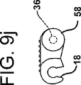
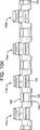
図9a−9jは、高摩擦の搬送表面CSを有するリンクセクション10の2つのことなる実施形態を示す。図9a−9eは、4つの側方に反復して設けられたリンク形部分12a−12dを有するリンクセクション10を示し、図9f−9jは、8つの側方に反復して設けられたリンク形部分12a−12hを有するリンクセクション10を示す。これらの2つのタイプのリンクセクション10は、れんが積み態様に(例えば、4+4、8、4+4、8・・・の順に、又は、4+8+8、8+8+4、8+4+8・・・の順に)積み重ねてベルト又はチェーンCの形に形成するように容易に適合させることができる。両実施形態に関連して図示されているように、高摩擦の搬送表面CSは、尖端部分14の少くとも一部分(例えば、上面20)と脚部分22,24の少くとも一部分(例えば、上面26)にディンプル又はディンプル状突起60を設けることによって形成することができる。突起60は、リンク形部分の成形工程中リンク形部分と一体に形成してもよく、あるいは、(例えば、同時成形によって、又は、接着剤によって)リンク10に付着される別個の構造体上に形成してもよい。突起60を有するリンクセクション10と、「正規の」リンク又はリンクセクションとを組み合わせて複合ベルトセクションを形成することもできる。
Figures 9a-9j show two different embodiments of the
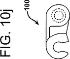
図10a−10jは、フラットトップ(頂面が平坦な)リンク100の2つの実施形態、即ち、4つの側方に反復して設けられたリンク形部分112a−112dを有するフラットトップリンク100と、8つの側方に反復して設けられたリンク形部分112a−112hを有するフラットトップリンク100を示す。このリンク100は、主として、各第2一体コネクタ140が搬送表面に間隙をつくる「樽状」部分ではなく、脚部分122,124の上面126(これも物品支持表面の一部を構成すると考えることができる)とほぼ同一平面をなす平坦な物品支持表面の形とされているという点で、上述したリンク10と異なる。第2コネクタ140の第1端130は、丸み付きとすることが好ましく、それに対応する第2端132は、2つのリンク100がスナップ嵌め係合状態で連結されたとき、隣接するリンクの丸み付き第1端130に係合するようになされた輪郭を有する嵌合湾曲面を備えたもとする。この第2コネクタ140の下側面は、駆動スプロケット又はアイドラースプロケットによって係合されるようになされた部分142を含むものとすることができる。この下面部分142には、上述した実施形態の第2コネクタ40(図5参照)の下面と同様な丸みを付すことができる。この実施形態では、上述した実施形態のオプションとしての短軸又は切頭コネクタ58が、搬送表面の一部を構成して搬送表面を完成するフラットトップ部分140の形に改変されている。このフラットトップ部分140も、駆動スプロケット又はアイドラースプロケットによって係合されるようになされた下面部分142を含むものとすることができる。
FIGS. 10a-10j illustrate two embodiments of a flat
これらのリンクの複数個を相互に連結すれば、切れ目のない、総体的に平坦な、平面状の物品支持表面を有するベルト又はチェーンCが得られる。この切れ目のない連続した物品支持表面即ち搬送表面は、パン菓子などの焼かれた食品のような食品を搬送する用途に用いるのに特に有利である。なぜなら、チェーンの上面を簡単に拭うだけで清掃することができるからである。所望ならば、この実施形態のリンク100にも、上述した態様で高摩擦の搬送表面を付与することができる。
By connecting a plurality of these links together, a belt or chain C having a flat, flat, article-supporting surface with no gaps is obtained. This unbroken continuous article support surface or transport surface is particularly advantageous for use in transporting food products such as baked food products such as baked goods. This is because it can be cleaned by simply wiping the upper surface of the chain. If desired, the
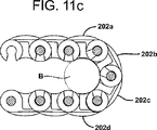
図11a−11cは、「湾曲トップ」(頂面が曲面状の)実施形態のリンク200を示す。この実施形態では、各リンク200は、上述したフラットトップ実施形態に実質的に類似した構造とすることができるが、実質的に連続した、凸面状又は弓状に湾曲した物品搬送表面202を有するという点で、フラットトップ実施形態とは異なる。図11bに明示されているように、この搬送表面202の輪郭は、リンク200の下面部分204の輪郭に実質的に合致する形状とすることができ、それによって、図に示されるように、リンク全体の断面形状を腎臓形にすることができる。これらのリンクから形成されたベルト又はベルトセクションは、ノーズバーB(図11cに仮想線で示されている)のような構造体の周りを回るとき、複数のリンクの搬送表面(例えば、図11cの表面202a,202b,202c,202d参照)が構造体の輪郭に追従し、外側表面に沿ってほぼ円形の輪郭を形成する(図11c参照)。これは、リンク200から形成されたベルト又はチェーンCが順方向走行路から戻り走行路へ、また、戻り走行路から順方向走行路へ移行する際、移行コンベヤに関連して通常設けられるブリッジ又はその他の構造体のフィンガーのような隣接する構造体に対して連続的に湾曲する表面を呈するという点で有利である。リンク200から形成されるこの実施形態のベルト又はチェーンCは、平坦な搬送表面を有する正規のピッチのリンクから成るベルト又はチェーンよりも、移行部を通過する織布又は布に似た挙動をし、ブリッジ、移行部又はその他の構造体に対して一定の割合で連続的に変化する表面を呈する。凸面状搬送表面202は、各リンク200と一体に形成してもよく、あるいは、「正規の」リンクセクション10,100に溶接、接着剤、スナップ嵌め等を用いて取り付けるための別個の部材に形成してもよい。
FIGS. 11 a-11 c show the
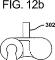
図12a及び12bは、搬送表面の一部を構成するほぼ直立したクリート302(突起又は桟)を備えた実施形態のリンク300を示す。これらのリンク300は、特定のタイプ又はサイズの物品に選択的に係合してそれらの物品を搬送することができるベルト又はベルトセクションを形成するために他のクリートなしのリンクと間隔を置いて組み合わせて設けることができる。あるいは別法として、特定の種類の物品に係合してそれらを搬送するための特殊なタイプの搬送表面を形成するためにクリートを有するリンク300と、クリートなしのリンクとをれんが積み態様に重ねることもできる。クリート302は単一でもそうでなくてもよい。
12a and 12b show an
図13a及び13bは、側方に反復して設けられたリンクセクション404の各々に、1対のほぼ直立した突片402、即ち、被搬送物品又は製品に係合するのを助成するための部分が設けられた、隆起トップ(頂面)を有する実施形態のリンク400を示す。突片402は、ほぼベルトの走行方向に向けられており、それらの物品係合能力を高めるために走行方向に対して僅かに角度を付すことができる。隆起トップ型リンクの代わりに、又は、それと組み合わせて、ブラシ付きトップ、すくい上げクリート又は側方に移動自在のガイドの使用も可能である。また、高摩擦表面を形成するために、1つ以上の外方に突出した弾性フィンガーを有する弾性インサートを各リンク又はリンクセクションの本体に周知の同時成形法を用いて組み込むことも可能である。
FIGS. 13a and 13b show a pair of substantially
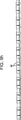
リンクセクション10,100,200,300は、添付図の幾つかにおいては多少拡大して示されているが、好ましくは、各リンクセクション10a,110bは、ほぼ6mmの高さHを有し(図4参照)、より好ましくは、約4mmの比較的低い高さを有する。また、リンク形部分12dの一端から仮想上の反対端(第2コネクタ40の中間点に位置する)までの寸法として測定される幅W(図4参照)は、約15mmである(従って、4mmの高さを有する例示のリンクの場合は、高さ対幅の比は1:3.75となり、6mmの高さを有する例示のリンクの場合は、高さ対幅の比は2.5となる)。かくして、4つの側方に反復して設けられたリンク形部分12a−12d(部分コネクタ58を含む)を有するリンクセクション10の幅は、約60mmとなり、8つのリンク形部分を有するリンクセクション10の幅は、約120mmとなる。受容部18のほぼ中心から第1コネクタ36の中心までの距離(一般にリンクのピッチを表し、通常、ベルト又はチェーンの「ピッチ」と称される、図2に符号Dで示される寸法)は、5mmとするいことが最も好ましい。従って、この好ましい寸法を有するリンクの「高さ対ピッチ」比(H/D)は、1つの有意の数値を挙げるとすれば、約1であり、より具体的に、2つの有意の数値を挙げるとすれば、約0.8(4mm/5mm)から約1.2(6mm/5mm)の範囲である。これらの比率の例は、成形上の欠陥や摩耗等から不可避的に生じる許容誤差を考慮せずに与えられたものである。また、これらの寸法は、すべて、好ましい実施形態を例示する目的で挙げられたものであり、本発明を限定するためのものではないことを理解されたい。
The
リンクセクション10a・・・10nから成るベルト又はチェーンCは、周知のタイプの支持台、レール等を含む任意の慣用の手段を用いて支持し、案内することができる。短軸型コネクタ58を設ける代わりに、本出願人の上記米国特許第4,953,693号及び5,031,757号に開示されているように、リンクセクション10の側方両端から側部アームを垂下させ、そのアームに、ガイドレール(図示せず)に係合するための内方に突出した案内耳片を形成してもよい。本発明の教示に従って形成される「正規の」サイズの、非「マイクロピッチ」リンクは、寸法が小さくされることによって強度が弱化することを配慮する度合いが少なくてすむので、上述したタイプの、垂下し、内方に突出した構造体を設けるのに適している。
The belt or chain C consisting of the
本発明の上述した教示に従って多くの変型が可能である。例えば、先に略述したように、側壁30,42は、各々が横断方向の一体コネクタ36,40を通る仮想の中心軸線に対してほぼ垂直になる向きとすることができる。この設計は、互いに隣接するリンクに相対枢動運動という点でより大きい自由度を与えることができる。また、4つのリンク形部分12a−12dが例示の目的で示されているが、2つだけのリンク形部分から成るリンク又はリンクセクションも可能である。リンク形部分の個数の限度は、リンクセクションを形成するのに用いられる素材の強度等の制約によってのみ制限される。もちろん、素材は、サイズや、特定の用途に応じていろいろなに変更される。
Many variations are possible in accordance with the above teachings of the present invention. For example, as outlined above, the
更に、第2一体コネクタ40の数も、特定の目的を達成するために必要に応じて又は所望に応じて調節することができる。例えば、4つのリンク形部分12a−12dから成るリンクセクションの場合、リンク形部分12aと12bの間と、12cと12dの間に1つずつ各々対応する駆動スプロケット又はアイドラースプロケットに係合するための第2一体コネクタ40を設けることができる。その場合、リンク形部分12bと12cは、それらの対応する脚部分22,24の外側側壁28の間の界面において単に結合して一体にすることができる(図示せず)。リンクセクション10a・・・10nから成るベルトがスプロケット駆動されるものではない場合は、第2一体コネクタ40を完全になくして、隣り合う脚部分22,24を単に結合して一体にしておけばよい。ただし、ベルト設計の容易さ及び製造上の融通性という点からみれば、同じ頻度で側方に反復して並置する対称的な(規則正しく繰り返している構造の)リンクセクション10a・・・10nを形成することが好ましい。
Furthermore, the number of second
尖端部分14と脚部分22,24の相対的なサイズ及び幅も、特定の結果を得るために必要に応じて変更することができる。例えば、僅かではあるが、より強固なリンクセクションが必要とされる場合は、脚部分22,24の幅を広くし、尖端部分14の横断方向、即ち幅方向の寸法を短くするのが有利である。受容部18及びコネクタ36,40のサイズ、形状及び相対的な向きも、リンクセクション10を強固にしたり、その他の望ましい結果を得るために必要に応じて変更することができる。更に、軽量プラスチック材で形成される「正規」ピッチ版のリンクセクション10においては、従来慣用のステンレス鋼製のコネクタロッドの代わりに一体のコネクタを使用することは、それらのリンクセクションから得られるベルト又はチェーンCの重量を相当に軽量化することができる。このことは、一般には、本発明によるこれらのリンクセクション10から形成されるベルト又はチェーンは、従来のステンレス鋼製のコネクタロッドを有するリンクセクションから形成されるものに比べて、所要支持力及び駆動力が小さくてすむことを意味する。
The relative sizes and widths of the
また、第1コネクタ36を内側側壁30と30の間に配置するが、一方の内側側壁30から他方の内側側壁30にまで完全には延長させない構成とするリンクセクション10の変型も可能である。その場合、第1コネクタ36は、各内側側壁30から内方に突出した2つの互いに間隔を置いて対向した短軸(図には示されていないが、部分突起58と同様なもの)から成るものとすることができる。この実施形態の場合、受容部18は、仕切り壁(図示せず)によって、各々第1コネクタ36を構成する短軸を受容する2つの受容部に分割することができる。この仕切り壁は、リンクセクション10の構造を強化する働きをするが、必須の要件ではなく、オプションとして形成することができる。ただし、この実施形態は。対向した2つの短軸は連続したコネクタ36より構造的にかなり弱いので、特に「マイクロピッチ」のベルトに適用するには、余り好適ではない。
Further, although the
また、各隣接するリンクセクションに同じプラスチック材を用いると、きしみ音を生じることがあることは斯界においてよく知られていることである。きしみ音が生じても、これらのリンクセクションから成るベルト又はチェーンの作動特性又は性能には影響はないが、不快なことではある。従って、互いに隣接して連結されるリンクセクションをそれぞれ異なる種類のプラスチック材で形成することが望ましいことに留意されたい。きしみ音をなくすために、あるいは、その他の任意の特性を得るために、適当なプラスチック材又はそれらの組合せを選択することは、当業者にとって設計事項であると考えられる。 It is also well known in the art that the use of the same plastic material for each adjacent link section can produce a squeak. The squeaking noise does not affect the operating characteristics or performance of the belts or chains comprising these link sections, but is uncomfortable. Accordingly, it should be noted that it is desirable to form the link sections that are connected adjacent to each other from different types of plastic materials. It would be a design matter for those skilled in the art to select an appropriate plastic material or a combination thereof to eliminate squeak noise or to obtain any other characteristic.
最後に、「マイクロピッチ」のベルト(即ち、約1.0の高さ対ピッチ比を有するリンクで形成されたベルト)を得るためにここに開示された寸法を有するリンクの場合、幅狭のベルト又はチェーンCを形成するために隣接する第1及び第2のリンク又はリンクセクション10a,10bとスナップ嵌め係合状態に連結するリンク形部分12を1つだけ設けることも可能である。そのようなリンク10及びそれらのリンク10a,10bで形成されたチェーンCの例が、図14a、14b、14c及び14dに示されている。そのようなリンクで形成された複数のチェーンを並置して一括して駆動し、1つのコンベヤとすることができる。
Finally, in the case of links having the dimensions disclosed herein to obtain a “micropitch” belt (ie, a belt formed of links having a height to pitch ratio of about 1.0) It is also possible to provide only one link-shaped portion 12 that is in snap-fit engagement with adjacent first and second links or
本発明の一側面を構成するリンク又はリンクセクション、及び、本発明の他の側面を構成するベルト又はベルトセクションのいろいろな実施形態の上記の記載は、例示の目的でなされたものであり、これらの記載は、本発明をここに開示された形態に厳密に限定するものではない。例えば、「尖端」や「脚」という用語は、各リンクセクション10の構造を説明するために用いられたものであり、リンクセクションを特定の形状、サイズ、向きに限定するためではなく、そのようなリンクセクションから形成されたベルトが2方向駆動が可能であることを限定するためでもない。
The above description of various embodiments of links or link sections that constitute one aspect of the invention and belts or belt sections that constitute the other aspects of the invention has been made for illustrative purposes only. The description is not intended to limit the invention to the precise form disclosed herein. For example, the terms “point” and “leg” are used to describe the structure of each
以上、本発明を実施形態に関連して説明したが、本発明は、ここに例示した実施形態の構造及び形状に限定されるものではなく、いろいろな実施形態が可能であり、いろいろな変更及び改変を加えることができることを理解されたい。 The present invention has been described above with reference to the embodiments. However, the present invention is not limited to the structures and shapes of the embodiments illustrated here, and various embodiments are possible. It should be understood that modifications can be made.
10 リンク、リンクセクション
12 リンク形部分
14 尖端部分
16 ノーズ、ノーズ部分
18 受容部
20 上面
22,24 脚部分
26 上面
28 外側側壁
30 内側側壁
32 先行凹部分
34 後行表面、後行部分
36 第1一体コネクタ
38 凹部、凹部分、後行凹部分
40 第2一体コネクタ
42 外側側壁
44 下面
46 入口
48 テーパー側壁、側壁
50 ベルトセクション
52 下面、最下方部分
54 最下方部分
56 下面
58 部分一体コネクタ、切頭コネクタ、短軸型コネクタ、部分突起
60 ディンプル状突起、突起
100 フラットトップリンク、リンク
112 リンク形部分
122,124 脚部分
126 上面
130,132 端
140 第2一体コネクタ
140 フラットトップ部分
142 下面部分、部分
200 リンク
201 下面部分
202 凸面状搬送表面、搬送表面
202 物品搬送表面
300 リンク
400 リンク
402 突片
404 リンクセクション
B ノーズバー
C コンベヤベルト、チェーン
CS 搬送表面
N 頸部
S スプロケット
W 幅
10 link, link section 12 link-shaped
Claims (20)
側方に反復して設けられた複数のリンク形部分を含む一体の本体から成り、該各リンク形部分は、被搬送物品又は製品に係合することができる、又は、それらを支持するのを助成することができる表面と、1対の脚部分と、該1対の脚部分の間に延設された少なくとも1つの第1一体コネクタと、隣接するリンクセクションの少なくとも1つの第1一体コネクタをスナップ嵌め係合状態で受容することができる受容部とを有し、該スナップ嵌め係合が、コンベヤベルトの一部分を形成するために各リンク又はリンクセクションと、隣接するリンク又はリンクセクションとの容易で、かつ、堅固な組み立てを可能にすることを特徴とするモジュラーリンクセクション。A modular link section for use in conjunction with an adjacent link or link section to form part of a conveyor belt for conveying articles or products,
Consists of a unitary body including a plurality of link-shaped portions that are repeatedly provided laterally, each link-shaped portion being capable of engaging with or supporting a conveyed article or product. a surface which can aid, and leg portions of the pair, and at least one first integral connector is extended between the leg portions of the pair, at least one first integral connector of the adjacent link section A receiving portion that can be received in a snap-fit engagement, wherein the snap-fit engagement facilitates each link or link section and adjacent links or link sections to form a portion of the conveyor belt. A modular link section that allows for robust assembly.
各々、被搬送物品又は製品に係合することができる、又は、それらを支持するのを助成することができる表面を有する、側方に反復して設けられた複数の尖端部分と、
該各尖端部分から突設された1対の脚部分と、
該各尖端部分の前記1対の脚部分の間に延設された少なくとも1つの一体コネクタと、
から成り、
各尖端部分は、隣接するリンクの少なくとも1つの一体コネクタをスナップ嵌め係合状態で受容することができる受容部を有し、該スナップ嵌め係合が、コンベヤベルトの一部分を形成するために該リンクと、隣接するリンクとの容易で、かつ、堅固な組み立てを可能にすることを特徴とする一体のモジュラーリンク。An integral modular link for use in conjunction with an adjacent link to form a portion or section of a conveyor belt for conveying articles or products,
A plurality of repetitively pointed side portions each having a surface that can engage or assist in supporting the article or product being conveyed;
A pair of leg portions projecting from the tip portions;
And at least one integral connectors extending between the leg portions of the pair of respective tip portions,
Consisting of
Each pointed portion has a receiving portion capable of receiving at least one integral connector of an adjacent link in a snap-fit engagement, the snap-fit engagement forming the link to form a portion of the conveyor belt. And an integral modular link characterized in that it allows easy and robust assembly with adjacent links.
側方に反復して設けられた少なくとも2つのリンク形部分から成り、該各リンク形部分は、被搬送物品又は製品に係合するように、又は、それらを支持するのを助成するように適合された尖端部分と、各尖端部分から突出した第1及び第2脚部分と、各リンク形部分の第1脚部分と第2脚部分の間に延設された少なくとも1つの第1一体コネクタと、第1のリンク形部分の一方の脚部分と、隣接する第2のリンク形部分の一方の脚部分との間に延設された第2一体コネクタと、隣接するリンクセクションの少なくとも1つの第1一体コネクタをスナップ嵌め係合状態で受容することができる受容部を有することを特徴とする一体のモジュラーリンクセクション。An integral modular link section for use in conjunction with an adjacent link section to form a portion of a conveyor belt for conveying articles or products,
Consists of at least two link-shaped portions that are repeatedly provided laterally, each link-shaped portion adapted to engage or assist in supporting the articles or products to be conveyed and it has been pointed portion, and first and second leg portion projecting from the tip portion, at least one first integral connector that is extending between the first leg portion and second leg portions of each link-shaped portion , A second integral connector extending between one leg portion of the first link-shaped portion and one leg portion of the adjacent second link-shaped portion, and at least one first of the adjacent link sections. A unitary modular link section having a receiving part capable of receiving the one-piece connector in a snap-fit engagement .
各々、側方に反復して設けられた複数のリンク形部分を含む複数の一体リンクセクションから成り、該各リンク形部分は、被搬送物品又は製品に係合するための、又は、それらを支持するのを助成するための表面と、1対の脚部分と、該1対の脚部分の間に延設された少なくとも1つの第1一体コネクタを含み、該リンクセクションのうちの第1のリンクセクションの前記各リンク形部分は、隣接する第2のリンクセクションに対して枢動しうるような態様に、該第2のリンクセクションの前記第1一体コネクタをスナップ嵌め係合状態で受容するための受容部を有し、該スナップ嵌め係合が、コンベヤベルトセクションを形成するために互いに隣接するリンクセクションの容易で、かつ、堅固な組み立てを可能にすることを特徴とするモジュラーリンクコンベヤベルトセクション。A modular link conveyor belt section for use in forming a portion of an endless conveyor belt for conveying articles or products,
Each comprises a plurality of integral link sections including a plurality of link-shaped portions provided repeatedly on the sides, each link-shaped portion for engaging with or supporting a conveyed article or product A first link of the link section, including a surface for assisting, a pair of leg portions, and at least one first integral connector extending between the pair of leg portions. Each link-shaped portion of a section receives the first integral connector of the second link section in a snap-fit engagement in such a manner that it can pivot relative to an adjacent second link section. And the snap-fit engagement allows easy and robust assembly of adjacent link sections to form a conveyor belt section. Error link conveyor belt section.
各々、側方に反復して設けられた複数のリンク形部分を含む複数の一体リンクセクションから成り、該各リンク形部分は、被搬送物品又は製品に係合するための、又は、それらを支持するのを助成するための表面と、1対の脚部分と、該1対の脚部分の間に延設された一体コネクタを有し、
前記リンクセクションのうちの第1のリンクセクションの各リンク形部分は、隣接する第2のリンクセクションに対して枢動しうるような態様に、該隣接する第2のリンクセクションの一体コネクタをスナップ嵌め係合状態で受容するための受容部を有し、
前記第1のリンクセクション及び第2のリンクセクションの下面は、これらのリンクセクションが所定量だけ枢動されたとき、それらのリンクセクションの下面が、前記ガイド構造体の輪郭に合致し、それによって、該ベルトセクションの該ガイド構造体の上を通り越しての円滑な走行を容易にする湾曲輪郭を呈するように、特別な輪郭の表面又は湾曲表面とされていることを特徴とするモジュラーリンクコンベヤベルトセクション。A modular link conveyor belt section for use in forming a portion of an endless conveyor belt capable of transporting articles or products and traveling along a relatively small diameter guide structure such as a nose bar;
Each comprises a plurality of integral link sections including a plurality of link-shaped portions provided repeatedly on the sides, each link-shaped portion for engaging with or supporting a conveyed article or product A surface for helping to do so, a pair of leg portions, and an integral connector extending between the pair of leg portions ;
Each link-shaped portion of the first link section of the link sections snaps the integral connector of the adjacent second link section in such a manner that it can pivot relative to the adjacent second link section. Having a receiving portion for receiving in a fitted engagement state ;
The bottom surfaces of the first and second link sections are such that when the link sections are pivoted by a predetermined amount, the bottom surfaces of the link sections conform to the contour of the guide structure, thereby A modular link conveyor belt characterized by a special contoured surface or curved surface to exhibit a curved contour that facilitates smooth travel over the guide structure of the belt section section.
各々、被搬送物品又は製品に係合することができる、又は、それらを支持するのを助成することができる表面と、1対の脚部分と、該1対の脚部分の間に延設された少なくとも1つの一体コネクタと、隣接するリンク又はリンクセクションの少なくとも1つの一体コネクタをスナップ嵌め係合状態で受容することができる受容部とを有する側方に反復して設けられた複数のリンク形部分から成り、該各リンク形部分の高さ対各リンク形部分の幅の比は、約3.75であり、それによって、互いに隣接するリンクセクションのスナップ嵌め係合が、コンベヤベルトの一部分を形成するために各リンクセクションと、隣接するリンク又はリンクセクションとの容易で、かつ、堅固な組み立てを可能にすることを特徴とする一体モジュラーリンクセクション。An integral modular link section for use in conjunction with an adjacent link or link section to form part of a conveyor belt for conveying articles or products,
Each extends between a surface that can engage or assist to support the article or product to be conveyed , a pair of leg portions, and the pair of leg portions. A plurality of link shapes provided repeatedly on the side having at least one integral connector and a receiving part capable of receiving at least one integral connector of an adjacent link or link section in a snap-fit engagement The ratio of the height of each link-shaped portion to the width of each link-shaped portion is about 3.75, so that the snap-fit engagement of adjacent link sections causes a portion of the conveyor belt to An integral modular link center characterized in that it allows easy and robust assembly of each link section and adjacent links or link sections to form Deployment.
各々、被搬送物品又は製品に係合することができる、又は、それらを支持するのを助成することができる表面と、1対の脚部分と、該1対の脚部分の間に延設された少なくとも1つの一体コネクタと、隣接するリンク又はリンクセクションの少なくとも1つの一体コネクタをスナップ嵌め係合状態で受容することができる受容部とを有する側方に反復して設けられた複数のリンク形部分から成り、該各リンク形部分の高さ対各リンク形部分の幅の比は、約2.5であり、それによって、互いに隣接するリンクセクションのスナップ嵌め係合が、コンベヤベルトの一部分を形成するために各リンクセクションと、隣接するリンク又はリンクセクションとの容易で、かつ、堅固な組み立てを可能にすることを特徴とする一体モジュラーリンクセクション。An integral modular link section for use in conjunction with an adjacent link or link section to form part of a conveyor belt for conveying articles or products,
Each extends between a surface that can engage or assist to support the article or product to be conveyed , a pair of leg portions, and the pair of leg portions. A plurality of link shapes provided repeatedly on the side having at least one integral connector and a receiving part capable of receiving at least one integral connector of an adjacent link or link section in a snap-fit engagement The ratio of the height of each link-shaped portion to the width of each link-shaped portion is about 2.5, so that the snap-fit engagement of adjacent link sections causes a portion of the conveyor belt to Integral modular link section characterized in that it allows easy and robust assembly of each link section and adjacent links or link sections to form ® down.
各々、1対の脚部分と、該1対の脚部分の間に延設された少なくとも1つの一体コネクタと、隣接する第1のリンクの少なくとも1つの一体コネクタをスナップ嵌め係合状態で受容することができる受容部と、隣接する第2のリンクと結合するためのコネクタと、被搬送物品又は製品に係合することができる、又は、それらを支持するのを助成することができる表面とを有する、側方に反復して設けられた少なくとも2つのリンク形部分から成り、該各リンク形部分の高さは、約6mm未満であり、
該スナップ嵌め係合が、コンベヤベルトの一部分を形成するために各リンクセクションと、隣接するリンク又はリンクセクションとの容易で、かつ、堅固な組み立てを可能にすることを特徴とする一体モジュラーリンク。An integral modular link for use in conjunction with adjacent first and second links to form a portion of a conveyor belt for conveying articles or products;
Each receives a pair of leg portions, at least one integral connector extending between the pair of leg portions, and at least one integral connector of an adjacent first link in a snap-fit engagement. A receiving portion capable of engaging, a connector for coupling with an adjacent second link, and a surface capable of engaging with or supporting the article or product to be conveyed. with, comprises at least two links shaped portion provided repeatedly laterally, the height of the each link-shaped portion is less than about 6 mm,
An integral modular link characterized in that the snap-fit engagement allows easy and rigid assembly of each link section and adjacent links or link sections to form part of the conveyor belt.
各々、被搬送物品又は製品に係合することができる、又は、それらを支持するのを助成することができる表面と、1対の脚部分と、該1対の脚部分の間に延設された少なくとも1つの第1一体コネクタと、隣接するリンクの少なくとも1つの第1一体コネクタをスナップ嵌め係合状態で受容することができる受容部とを有する、側方に反復して設けられた複数のリンク形部分から成り、
第2一体コネクタが、互いに隣接するリンク形部分の前記脚部分の間に延在して物品支持表面の少なくとも一部分を画定し、それによって、実質的に連続した切れ目のない物品支持表面が得られることを特徴とする一体モジュラーリンクセクション。An integral modular link section for use in conjunction with an adjacent link or link section to form part of a conveyor belt for conveying articles or products,
Each extends between a surface that can engage or assist to support the article or product to be conveyed, a pair of leg portions, and the pair of leg portions. A plurality of repetitively provided laterally having at least one first integral connector and a receptacle capable of receiving at least one first integral connector of an adjacent link in a snap-fit engagement. It consists of a link-shaped part,
A second integral connector extends between the leg portions of adjacent link-shaped portions to define at least a portion of the article support surface, thereby providing a substantially continuous, unbroken article support surface. Integrated modular link section characterized by that.
各々、被搬送物品又は製品に係合するための、又は、それらを支持するのを助成するための表面と、1対の脚部分と、該1対の脚部分の間に延設された一体コネクタを有する、側方に反復して設けられた複数のリンク形部分を有する複数の一体リンクセクションから成り、
該リンクセクションのうちの第1のリンクセクションの各リンク形部分は、隣接する第2のリンクセクションに対して枢動しうるような態様に、第2のリンクセクションの一体コネクタをスナップ嵌め係合状態で受容するための受容部を含み、
該各リンクセクションの少なくとも一部分は、高摩擦性搬送表面を有することを特徴とするモジュラーリンクコンベヤベルトセクション。A modular link conveyor belt section for use in forming a portion of an endless conveyor belt capable of conveying articles or products,
Each surface for engaging with or assisting to support the article or product to be conveyed, a pair of leg portions, and an integral extending between the pair of leg portions Comprising a plurality of integral link sections having a plurality of link-shaped portions provided repeatedly on the sides, having connectors,
Each link-shaped portion of the first link section of the link sections snap-fits the integral connector of the second link section in such a manner that it can pivot relative to the adjacent second link section. Including a receiving part for receiving in a state ,
A modular link conveyor belt section, wherein at least a portion of each link section has a highly frictional conveying surface.
各々、側方に反復して設けられた複数のリンク形部分を含む複数の一体リンクセクションから成り、該各リンクセクションは、被搬送物品又は製品に係合するための、又は、それらを支持するのを助成するための表面と、1対の脚部分と、該1対の脚部分の間に延設された少なくとも1つの第1一体コネクタを有し、
前記リンクセクションのうちの第1のリンクセクションの各リンク形部分は、隣接する第2のリンクセクションに対して枢動しうるような態様に、該第2のリンクセクションの第1一体コネクタをスナップ嵌め係合状態で受容するための受容部を含み、
第1のリンク形部分の一方の脚部分と、隣接する第2のリンク形部分の脚部分との間に第2一体コネクタが設けられていることを特徴とするモジュラーリンクコンベヤベルトセクション。A modular link conveyor belt section for use in forming a portion of an endless conveyor belt capable of conveying articles or products,
Each comprises a plurality of integral link sections including a plurality of link-shaped portions provided repeatedly on the sides, each link section engaging or supporting the article or product to be conveyed A pair of leg portions, and at least one first integral connector extending between the pair of leg portions ;
Each link-shaped portion of the first link section of the link sections snaps the first integral connector of the second link section in such a manner that it can pivot relative to the adjacent second link section. Including a receiving portion for receiving in a fitted engagement state ;
A modular link conveyor belt section, wherein a second integral connector is provided between one leg portion of the first link-shaped portion and the leg portion of the adjacent second link-shaped portion.
各々、被搬送物品又は製品に係合することができる、又は、それらを支持するのを助成することができる表面と、1対の脚部分と、該1対の脚部分の間に延設された少なくとも1つの第1一体コネクタと、隣接するリンクセクションの少なくとも1つの第1一体コネクタをスナップ嵌め係合状態で受容することができる受容部とを有する、側方に反復して設けられた複数のリンク形部分から成り、
第2一体コネクタが、互いに隣接するリンク形部分の前記脚部分の間に延在して物品支持表面の物品支持表面の連続した一部分を画定し、該各リンク形部分の該物品支持表面は、凸面、又は、所定の曲率を有する曲面に形成されていることを特徴とする一体モジュラーリンクセクション。An integral modular link section for use in conjunction with an adjacent link or link section to form part of a conveyor belt for conveying articles or products,
Each extends between a surface that can engage or assist to support the article or product to be conveyed, a pair of leg portions, and the pair of leg portions. A plurality of side-repetitively provided plurality having at least one first integral connector and a receptacle capable of receiving at least one first integral connector of an adjacent link section in a snap-fit engagement. The link-shaped part of
A second integral connector extends between the leg portions of adjacent link-shaped portions to define a continuous portion of the article support surface of the article support surface, the article support surface of each link-shaped portion comprising: A monolithic modular link section formed on a convex surface or a curved surface having a predetermined curvature.
各々、側方に反復して設けられた複数のリンク形部分を含む複数の一体リンクセクションから成り、該各リンクセクションは、被搬送物品又は製品に係合するための、又は、それらを支持するのを助成するための表面と、1対の脚部分と、該1対の脚部分の間に延設された一体コネクタを有し、
リンクセクションのうちの第1のリンクセクションの各リンク形部分は、隣接する第2のリンクセクションに対して枢動しうるような態様に、第2のリンクセクションの一体コネクタをスナップ嵌め係合状態で受容するための受容部を含み、
該各リンク形部分の物品支持表面は、断面でみてほぼ凸面状であることを特徴とするモジュラーリンクコンベヤベルトセクション。A modular link conveyor belt section for use in forming a portion of an endless conveyor belt capable of transporting articles or products and traveling along a relatively small diameter guide structure such as a nose bar;
Each comprises a plurality of integral link sections including a plurality of link-shaped portions provided repeatedly on the sides, each link section engaging or supporting the article or product to be conveyed A pair of leg portions and an integral connector extending between the pair of leg portions ;
Each link-shaped portion of the first link section of the link sections is snapped into engagement with the integral connector of the second link section so that it can pivot relative to the adjacent second link section. in comprises a receiving portion for receiving,
A modular link conveyor belt section, wherein the article support surface of each link-shaped portion is substantially convex in cross section.
各々、被搬送物品又は製品に係合することができる、又は、それらを支持するのを助成することができる表面と、1対の脚部分と、該1対の脚部分の間に延設された少なくとも1つの第1一体コネクタと、隣接するリンクの少なくとも1つの第1一体コネクタをスナップ嵌め係合状態で受容することができる受容部とを有する側方に反復して設けられた複数のリンク形部分から成り、
第2一体コネクタが、互いに隣接するリンク形部分の脚部分の間に延在して物品支持表面の一部分を画定しており、
各リンク形部分の物品支持表面に少なくとも1つの直立したクリートが設けられていることを特徴とする一体モジュラーリンクセクション。An integral modular link section for use in conjunction with an adjacent link or link section to form part of a conveyor belt for conveying articles or products,
Each extends between a surface that can engage or assist to support the article or product to be conveyed, a pair of leg portions, and the pair of leg portions. A plurality of links provided repeatedly in a lateral direction having at least one first integral connector and a receiving portion capable of receiving at least one first integral connector of an adjacent link in a snap-fit engagement. Consists of shape parts,
A second integral connector extends between leg portions of adjacent link-shaped portions to define a portion of the article support surface;
An integral modular link section characterized in that at least one upstanding cleat is provided on the article support surface of each link-shaped part.
各々、側方に反復して設けられた複数のリンク形部分を含む複数の一体リンクセクションから成り、該各リンク形部分は、被搬送物品又は製品に係合するための、又は、それらを支持するのを助成するための表面と、1対の脚部分と、該1対の脚部分の間に延設された一体コネクタを有し、
前記リンクセクションのうちの第1のリンクセクションの各リンク形部分は、隣接する第2のリンクセクションに対して枢動しうるような態様に、第2のリンクセクションの一体コネクタをスナップ嵌め係合状態で受容するための受容部を含み、
該各リンク形部分は、ほぼ直立したクリートを有することを特徴とするモジュラーリンクコンベヤベルトセクション。A modular link conveyor belt section for use in forming a portion of an endless conveyor belt capable of conveying articles or products,
Each comprises a plurality of integral link sections including a plurality of link-shaped portions provided repeatedly on the sides, each link-shaped portion for engaging with or supporting a conveyed article or product A surface for helping to do so, a pair of leg portions, and an integral connector extending between the pair of leg portions ;
Each link-shaped portion of the first link section of the link sections is snapped into engagement with the integral connector of the second link section in such a manner that it can pivot relative to the adjacent second link section. Including a receiving part for receiving in a state ,
A modular link conveyor belt section, wherein each link-shaped portion has a substantially upright cleat.
各々、被搬送物品又は製品に係合することができる、又は、それらを支持するのを助成することができる表面と、1対の脚部分と、該1対の脚部分の間に延設された少なくとも1つの第1一体コネクタと、隣接するリンクセクションの少なくとも1つの第1一体コネクタをスナップ嵌め係合状態で受容することができる受容部と、1対の直立した突片とを有する側方に反復して設けられた複数のリンク形部分から成り、
第2一体コネクタが、互いに隣接するリンク形部分の脚部分の間に延在して物品支持表面の物品支持表面の一部分を画定することを特徴とする一体モジュラーリンクセクション。An integral modular link section for use in conjunction with an adjacent link or link section to form part of a conveyor belt for conveying articles or products,
Each extends between a surface that can engage or assist to support the article or product to be conveyed, a pair of leg portions, and the pair of leg portions. side having at least one first integral connector, a receiving portion for at least one first integral connector may be received in snap-fit engagement of the adjacent links section, and a pair upright projecting pieces of Consisting of a plurality of link-shaped portions repeatedly provided in
An integral modular link section, wherein the second integral connector extends between leg portions of adjacent link-shaped portions to define a portion of the article support surface of the article support surface.
各々、側方に反復して設けられた複数のリンク形部分を含む複数の一体リンクセクションから成り、該各リンク形部分は、被搬送物品又は製品に係合するための、又は、それらを支持するのを助成するための表面と、1対の脚部分と、該1対の脚部分の間に延設された一体コネクタと、1対の直立した突片を有し、
前記リンクセクションのうちの第1のリンクセクションの各リンク形部分は、隣接する第2のリンクセクションに対して枢動しうるような態様に、第2のリンクセクションの一体コネクタをスナップ嵌め係合状態で受容するための受容部を含むことを特徴とするモジュラーリンクコンベヤベルトセクション。A modular link conveyor belt section for use in forming a portion of an endless conveyor belt capable of transporting articles or products and traveling along a relatively small diameter guide structure such as a nose bar;
Each comprises a plurality of integral link sections including a plurality of link-shaped portions provided repeatedly on the sides, each link-shaped portion for engaging with or supporting a conveyed article or product A surface for helping to do so, a pair of leg portions, an integral connector extending between the pair of leg portions, and a pair of upstanding protrusions;
Each link-shaped portion of the first link section of the link sections is snapped into engagement with the integral connector of the second link section in such a manner that it can pivot relative to the adjacent second link section. A modular link conveyor belt section comprising a receiving portion for receiving in a state .
各々、1対の脚部分と、該1対の脚部分の間に延設された少なくとも1つの一体コネクタと、隣接する第1のリンクの少なくとも1つの一体コネクタをスナップ嵌め係合状態で受容することができる受容部と、隣接する第2のリンクによって受容されるように構成されたコネクタと、被搬送物品又は製品に係合することができる、又は、それらを支持するのを助成することができる表面とを有する、側方に反復して設けられた少なくとも2つのリンク形部分から成り、該リンクの高さ対該リンクのピッチの比は、約1.0であることを特徴とする一体リンク。An integral link for use in snap-fit engagement with adjacent first and second links to form a portion of a conveyor belt or chain for conveying articles or products,
Each receives a pair of leg portions, at least one integral connector extending between the pair of leg portions, and at least one integral connector of an adjacent first link in a snap-fit engagement. Capable of engaging or supporting a supported article or product, and a connector configured to be received by an adjacent second link. and a surface that can be made from at least two links shaped portion provided repeatedly laterally, the ratio of the pitch height Tai該link of the link is integral, characterized in that it is approximately 1.0 Link.
各々、1対の脚部分と、該1対の脚部分の間に延設された少なくとも1つの一体コネクタと、隣接する第1のリンクの少なくとも1つの一体コネクタをスナップ嵌め係合状態で受容することができる受容部と、隣接する第2のリンクによって受容されるように構成されたコネクタと、被搬送物品又は製品に係合することができる、又は、それらを支持するのを助成することができる表面とを有する、側方に反復して設けられた少なくとも2つのリンク形部分から成り、該リンクの高さ対該リンクのピッチの比は、約0.8より大きいことを特徴とする一体リンク。An integral link for use in snap-fit engagement with adjacent first and second links to form a portion of a conveyor belt or chain for conveying articles or products,
Each receives a pair of leg portions, at least one integral connector extending between the pair of leg portions, and at least one integral connector of an adjacent first link in a snap-fit engagement. Capable of engaging or supporting a supported article or product, and a connector configured to be received by an adjacent second link. and a surface that can be made from at least two links shaped portion provided repeatedly laterally, the ratio of the pitch height Tai該link of the link is integral, characterized in that greater than about 0.8 Link.
該各一体リンクは、各々、1対の脚部分と、該1対の脚部分の間に延設された少なくとも1つの一体コネクタと、隣接する第1のリンクの少なくとも1つの一体コネクタをスナップ嵌め係合状態で受容することができる受容部と、隣接する第2のリンクによって受容されるように構成されたコネクタと、被搬送物品又は製品に係合することができる、又は、それらを支持するのを助成することができる表面とを有する、側方に反復して設けられた少なくとも2つのリンク形部分から成り、該リンクの高さ対該リンクのピッチの比は、約1.0であることを特徴とするコンベアベルト又はチェーン。A conveyor belt or chain comprising a plurality of integral links configured to engage one another in a snap-fit engagement,
Respective integral links are each a leg portion of the pair, and at least one integral connector is extended between the leg portions of the pair, snapped at least one integral connector of the first adjacent links A receiving portion that can be received in an engaged state, a connector configured to be received by an adjacent second link, and can engage with or support a conveyed article or product and a surface that can assist in consists of at least two links shaped portion provided repeatedly laterally, the ratio of the pitch height Tai該link of the link is about 1.0 A conveyor belt or chain characterized by that.
Applications Claiming Priority (4)
| Application Number | Priority Date | Filing Date | Title |
|---|---|---|---|
| US35958202P | 2002-02-26 | 2002-02-26 | |
| US42306702P | 2002-11-01 | 2002-11-01 | |
| US43522102P | 2002-12-18 | 2002-12-18 | |
| PCT/US2003/005666 WO2003072464A1 (en) | 2002-02-26 | 2003-02-26 | Rodless conveyor belt or chain |
Publications (3)
| Publication Number | Publication Date |
|---|---|
| JP2005518322A JP2005518322A (en) | 2005-06-23 |
| JP2005518322A5 JP2005518322A5 (en) | 2006-03-16 |
| JP4445269B2 true JP4445269B2 (en) | 2010-04-07 |
Family
ID=27767847
Family Applications (1)
| Application Number | Title | Priority Date | Filing Date |
|---|---|---|---|
| JP2003571180A Expired - Fee Related JP4445269B2 (en) | 2002-02-26 | 2003-02-26 | Conveyor belt or chain without rod |
Country Status (10)
| Country | Link |
|---|---|
| US (2) | US7314132B2 (en) |
| EP (1) | EP1487723B1 (en) |
| JP (1) | JP4445269B2 (en) |
| AT (1) | ATE381502T1 (en) |
| AU (1) | AU2003213562A1 (en) |
| CA (1) | CA2477145C (en) |
| DE (1) | DE60318187T2 (en) |
| DK (1) | DK1487723T3 (en) |
| MX (1) | MXPA04008160A (en) |
| WO (1) | WO2003072464A1 (en) |
Families Citing this family (49)
| Publication number | Priority date | Publication date | Assignee | Title |
|---|---|---|---|---|
| US6959803B1 (en) * | 2002-12-18 | 2005-11-01 | Span Tech Llc | Self-tensioning conveyor |
| US20070187214A1 (en) * | 2003-10-23 | 2007-08-16 | Halbesma Joan A | Flexible conveyor for conveying exceptionally heavy loads |
| EP1588958A3 (en) * | 2004-04-22 | 2006-03-22 | uni-chains A/S | Clean Belt |
| US7455732B2 (en) * | 2004-08-13 | 2008-11-25 | Ppg Industries Ohio, Inc. | Apparatus and systems for coating objects |
| US7278535B2 (en) * | 2004-11-10 | 2007-10-09 | Ped Invest A/S | Net belt |
| ES2265293B1 (en) * | 2005-07-28 | 2008-02-16 | Thyssenkrupp Norte, S.A. | MOBILE HALL. |
| NL1030155C2 (en) * | 2005-10-10 | 2007-04-11 | Rexnord Flattop Europe Bv | Transporter. |
| US7517270B2 (en) * | 2006-05-30 | 2009-04-14 | Minds-I, Inc. | Construction system |
| US20080075528A1 (en) * | 2006-09-22 | 2008-03-27 | Michael Marzetta | Construction system |
| US7410225B1 (en) * | 2007-03-14 | 2008-08-12 | Minds-I, Inc. | Multi-part links for endless track |
| US7360644B1 (en) | 2007-03-23 | 2008-04-22 | Habasit Ag | Modular belt with rodless hinge |
| ES2283237B1 (en) | 2007-04-23 | 2008-08-01 | Angel Carmelo San Miguel Zarzuela | LINK FOR CONVEYOR CHAINS AND CHAIN OBTAINED WITH THE SAME. |
| US20090017716A1 (en) * | 2007-07-11 | 2009-01-15 | Michael Marzetta | Construction system |
| US7874419B2 (en) * | 2007-07-19 | 2011-01-25 | Dorner Mfg. Corp. | Contained drive system for chain conveyor belt to reduce catenary sag |
| US7841923B2 (en) * | 2007-11-13 | 2010-11-30 | Minds-I, Inc. | Vehicle axle joint for a toy vehicle |
| US7624858B2 (en) * | 2007-12-21 | 2009-12-01 | Habasit Ag | Modular plastic conveyor belt for spiral conversion |
| US7635060B2 (en) * | 2008-02-06 | 2009-12-22 | Laitram, L.L.C. | Apparatus and method for sensing conditions local to a modular conveyor belt |
| US8042597B2 (en) * | 2009-04-27 | 2011-10-25 | Lutron Electronics Co., Inc. | Roller shade system having hembar for pleating a shade fabric |
| US8113340B1 (en) | 2009-02-03 | 2012-02-14 | Hormel Foods Corporation | Modular conveyer belt |
| DE102009020304A1 (en) * | 2009-05-07 | 2010-11-25 | Hastem-Müller, Stefan | Link for a link band |
| JP2011172766A (en) * | 2010-02-24 | 2011-09-08 | Fujifilm Corp | Torque transmission device |
| EP2605984B1 (en) * | 2010-08-19 | 2016-06-01 | Laitram, LLC | Two-material conveyor belt module |
| DK177377B1 (en) * | 2011-07-05 | 2013-02-25 | Ammeraal Beltech Modular As | Modular belt module |
| DE102012103078A1 (en) * | 2012-04-10 | 2013-10-10 | Krones Ag | Chain conveyor for plastic preforms |
| WO2014066556A1 (en) | 2012-10-25 | 2014-05-01 | Solus Industrial Innovations, Llc | Device and method for controlling the wear of the rail of a conveyor |
| MX2015006770A (en) | 2012-11-29 | 2015-10-29 | Solus Ind Innovations Llc | Side-flexing conveyors. |
| NL2011934C2 (en) * | 2013-12-10 | 2015-06-11 | Rexnord Flattop Europe Bv | Module for a conveyor chain and modular conveyor chain. |
| US9663298B2 (en) * | 2014-12-18 | 2017-05-30 | Laitram, L.L.C. | Conveyor belt module with shaped bottom surface |
| IL243145B (en) * | 2014-12-24 | 2019-06-30 | System and methods for assembling chain elements using a coupling mechanism | |
| US10315847B2 (en) | 2014-12-31 | 2019-06-11 | Prince Castle LLC | Extruded slat/link conveyance chain |
| US10464757B2 (en) | 2014-12-31 | 2019-11-05 | Prince Castle LLC | Sprocket driven conveyor belt link and conveyor belt assembly |
| NL2014355B1 (en) * | 2015-02-26 | 2016-10-13 | Kaak Groep B V | Linked conveyor belt and method of manufacturing a linked conveyor belt. |
| US9889992B1 (en) | 2015-05-13 | 2018-02-13 | Prince Castle LLC | Conveyor belt slat |
| US9908708B1 (en) * | 2015-05-13 | 2018-03-06 | Prince Castle LLC | Conveyor belt link with coupling mechanism |
| US10752446B2 (en) * | 2015-09-25 | 2020-08-25 | Habasit Ag | Hybrid modular belt |
| EP3199477B1 (en) | 2016-01-27 | 2019-07-17 | Prince Castle LLC | A slat for a chain conveyor belt and a conveyor belt system comprising the same |
| USD804137S1 (en) * | 2016-02-23 | 2017-11-28 | Span Tech Llc | Conveyor link |
| US20180000284A1 (en) * | 2016-06-29 | 2018-01-04 | Prince Castle LLC | Continuous conveyor belt for food heating device |
| US10308433B2 (en) | 2016-06-29 | 2019-06-04 | Prince Castle LLC | Conveyor belt slat with side carrier connection |
| US10723560B2 (en) | 2016-11-18 | 2020-07-28 | Prince Castle LLC | Side-by-side snap on slats for a chain conveyor belt and conveyor belt system comprising same |
| DE102017113096A1 (en) * | 2017-06-14 | 2018-12-20 | Ketten-Wulf Betriebs-Gmbh | Modular conveyor belt |
| EP3652091B1 (en) * | 2017-07-10 | 2023-11-22 | Laitram, LLC | Belt conveyor and modular conveyor belt for inclines |
| US10843871B2 (en) | 2017-12-01 | 2020-11-24 | Prince Castle LLC | Side-by-side slats for a chain conveyor belt and conveyor belt system comprising same |
| CN108482944B (en) * | 2018-03-30 | 2024-01-02 | 浙江工业职业技术学院 | Double-roller turning conveyor |
| WO2020163270A1 (en) | 2019-02-06 | 2020-08-13 | Laitram, L.L.C. | Modular conveyor belt with hook hinges |
| US11279563B2 (en) * | 2019-12-17 | 2022-03-22 | Cambridge International, Inc. | Systems and methods for a wire plate conveyor belt |
| USD919922S1 (en) | 2019-12-17 | 2021-05-18 | Cambridge International, Inc. | Conveyor belt |
| EP4087798A1 (en) * | 2020-01-06 | 2022-11-16 | Laitram, L.L.C. | Modular conveyor belt with dedicated access assembly |
| USD998059S1 (en) * | 2021-07-14 | 2023-09-05 | Jinfeng Cai | Marble run toy |
Family Cites Families (59)
| Publication number | Priority date | Publication date | Assignee | Title |
|---|---|---|---|---|
| US382554A (en) * | 1888-05-08 | Detachable-link chain | ||
| US377120A (en) | 1888-01-31 | Drive-chain | ||
| US237591A (en) * | 1881-02-08 | Detachable drive-chain | ||
| US2695095A (en) * | 1950-12-05 | 1954-11-23 | Mathews Conveyer Co | Conveyer chain link |
| US3069923A (en) * | 1960-11-17 | 1962-12-25 | Kropp Forge Co | Link member |
| DE1183014B (en) * | 1961-04-20 | 1964-12-03 | Alfred Schmermund | Press chain for feeding tobacco, e.g. B. to tobacco cutters |
| US3160024A (en) * | 1964-05-05 | 1964-12-08 | Oliver W Mojonnier | Link member |
| US3415136A (en) * | 1967-03-13 | 1968-12-10 | Oliver W. Mojonnier | Link chain |
| US3513965A (en) * | 1968-10-21 | 1970-05-26 | Eldon S Miller | Conveyor and link |
| US3628834A (en) * | 1969-09-03 | 1971-12-21 | Baychem Corp | Link members and endless chains especially for tracked vehicles |
| NL7202250A (en) | 1972-02-21 | 1973-08-23 | ||
| FR2214244A5 (en) * | 1973-01-13 | 1974-08-09 | Fischer Artur | |
| FR2279047A1 (en) * | 1974-07-19 | 1976-02-13 | Ugine Carbone | NEW OVEN SOLE |
| DE2909893C2 (en) * | 1979-03-14 | 1982-07-29 | Heinrich Schlick KG, GmbH & Co, 4402 Greven | Belt for a trough belt cleaning device |
| US4597747A (en) * | 1980-11-26 | 1986-07-01 | The Laitram Corporation | Detachable link chain |
| US4473365A (en) * | 1980-11-26 | 1984-09-25 | Lapeyre James M | Detachable link chain |
| US4882901A (en) * | 1980-11-26 | 1989-11-28 | The Laitram Corporation | Detachable link chain |
| US4815270A (en) * | 1980-11-26 | 1989-03-28 | Lapeyre James M | Detachable link chain |
| US4815271A (en) * | 1980-11-26 | 1989-03-28 | The Laitram Corporation | Detachable link chain |
| US4394901A (en) * | 1980-12-16 | 1983-07-26 | Ashworth Bros., Inc. | Modular plastic conveyor belt |
| NZ211988A (en) | 1985-05-06 | 1990-12-21 | Napier Tool & Die Co | Conveyor belt element; elements join to make up endless conveyor without need for separate pin |
| USD307707S (en) * | 1987-01-29 | 1990-05-08 | Ab Skf | Conveyor chain link |
| US4953693A (en) * | 1989-01-23 | 1990-09-04 | Span Tech Corporation | Modular link conveyor system |
| US4951457A (en) * | 1989-11-08 | 1990-08-28 | Deal Douglas O | Narrow pitch articulated chain and links therefor |
| US5031757A (en) * | 1989-12-26 | 1991-07-16 | Span Tech Corporation | Modular link conveyor system with narrow chain |
| US5181601A (en) * | 1990-10-09 | 1993-01-26 | Palmaer K V | Plastic conveyor belt with integral sideplate |
| SE9004102D0 (en) * | 1990-12-21 | 1990-12-21 | Skf Specialty Product Ab | PLASTIC CHAIN AND INSTALLABLE LOADING LEATHER RESPECTIVE STEERING STEP |
| US5197591A (en) * | 1992-02-11 | 1993-03-30 | Ashworth Bros., Inc. | Replaceable snap-on modular overlay for rod and link turn-curve conveyor belts |
| US5125504A (en) * | 1991-03-08 | 1992-06-30 | Rexnord Corporation | Modular conveyor chain having open hinge pin construction |
| US5215185A (en) * | 1992-09-08 | 1993-06-01 | Rexnord Corporation | Breakable molded plastic links for forming conveyor chain |
| US5562200A (en) * | 1994-03-25 | 1996-10-08 | Maryland Wire Belts, Inc. | Unitary components and modular belt assembly |
| NL9301355A (en) * | 1993-08-03 | 1995-03-01 | Mcc Nederland | Transport mat built from plastic modules and modules for such a transport mat. |
| US5346060A (en) * | 1993-08-31 | 1994-09-13 | Precision Handling Devices, Inc. | Link assemblies which are interconnected to provide a self-tensioning conveyor belt |
| GB2282115A (en) | 1993-09-22 | 1995-03-29 | Kelvin Taylor Robertson | Interconnecting conveyor modules |
| US5797820A (en) * | 1995-09-22 | 1998-08-25 | Yamakyu Chain Co., Ltd. | Slat band chain and sprocket |
| NL1002501C2 (en) * | 1996-03-01 | 1997-09-03 | Mcc Nederland | Plastic module for a transport mat. |
| US6223889B1 (en) * | 1996-06-10 | 2001-05-01 | Span Tech Llc | Modular link conveyor with interdigitating grid and interleaving side wings |
| US5964340A (en) * | 1997-03-06 | 1999-10-12 | Dolan; Rex H. | Transfer conveyor |
| US5967296A (en) | 1997-03-06 | 1999-10-19 | Dolan; Rex H. | Transfer conveyor |
| USD427898S (en) * | 1997-04-02 | 2000-07-11 | Sinapore Technologies Automotive Limited | Tracked link body |
| USD420483S (en) | 1997-10-06 | 2000-02-08 | Flexlink Systems Ab | Chain-link to a conveyor |
| USD419742S (en) * | 1997-10-06 | 2000-01-25 | Flexlink Systems Ab | Chain-link to a conveyor |
| US6158575A (en) * | 1998-04-28 | 2000-12-12 | Berg Technology, Inc. | Links for forming a connector transport chain |
| US6138820A (en) * | 1998-05-15 | 2000-10-31 | Westar Mfg. Corp. | Conveyor chain link |
| JP2000072214A (en) * | 1998-08-31 | 2000-03-07 | Tsubakimoto Chain Co | Low-friction resin conveyer chain |
| GB9920932D0 (en) * | 1999-09-03 | 1999-11-10 | Boc Group Plc | Chain clamp |
| US6347699B1 (en) * | 1999-11-08 | 2002-02-19 | Earl Ramsey | Conveyor chain link |
| JP3448255B2 (en) * | 2000-03-24 | 2003-09-22 | 株式会社椿本チエイン | Transport chains used for orthogonal delivery conveyors |
| US6364095B1 (en) * | 2000-04-13 | 2002-04-02 | Span Tech Llc | Modular conveyor system with side flexing belt having roller support |
| US6305530B1 (en) * | 2000-05-30 | 2001-10-23 | Habasit Ag | Module for a modular conveying belt |
| US6382404B1 (en) * | 2000-12-21 | 2002-05-07 | Habasit Ag | Corrugated flight module |
| US6732856B2 (en) * | 2001-02-27 | 2004-05-11 | Maryland Wire Belts, Inc. | Modular conveyor belt |
| US6443795B1 (en) * | 2001-09-11 | 2002-09-03 | Wen-Pin Lin | Transmission chain for toys |
| USD473032S1 (en) * | 2002-01-15 | 2003-04-08 | Larry Altom | Modular plastic conveyor belt component |
| USD483168S1 (en) * | 2002-08-13 | 2003-12-02 | Span Tech Llc | Modular guide link for conveyor chain |
| US6874617B1 (en) * | 2003-09-26 | 2005-04-05 | Span Tech Llc | Modular link conveyor chain with rotatable article engaging assemblies |
| US7108126B2 (en) * | 2003-12-10 | 2006-09-19 | Span Tech, Llc | Side-flexing conveyor chain having twin transverse connectors |
| US7367447B1 (en) * | 2006-11-03 | 2008-05-06 | Habasit Ag | Rodless modular conveyor belt |
| US7360644B1 (en) * | 2007-03-23 | 2008-04-22 | Habasit Ag | Modular belt with rodless hinge |
-
2003
- 2003-02-26 DK DK03711243T patent/DK1487723T3/en active
- 2003-02-26 WO PCT/US2003/005666 patent/WO2003072464A1/en active IP Right Grant
- 2003-02-26 AU AU2003213562A patent/AU2003213562A1/en not_active Abandoned
- 2003-02-26 DE DE60318187T patent/DE60318187T2/en not_active Expired - Lifetime
- 2003-02-26 MX MXPA04008160A patent/MXPA04008160A/en active IP Right Grant
- 2003-02-26 JP JP2003571180A patent/JP4445269B2/en not_active Expired - Fee Related
- 2003-02-26 US US10/505,943 patent/US7314132B2/en not_active Expired - Lifetime
- 2003-02-26 EP EP03711243A patent/EP1487723B1/en not_active Expired - Lifetime
- 2003-02-26 CA CA2477145A patent/CA2477145C/en not_active Expired - Fee Related
- 2003-02-26 AT AT03711243T patent/ATE381502T1/en active
-
2007
- 2007-08-15 US US11/839,284 patent/US7559422B2/en not_active Expired - Lifetime
Also Published As
| Publication number | Publication date |
|---|---|
| CA2477145C (en) | 2011-04-05 |
| US20080023303A1 (en) | 2008-01-31 |
| MXPA04008160A (en) | 2005-06-08 |
| US7559422B2 (en) | 2009-07-14 |
| AU2003213562A1 (en) | 2003-09-09 |
| US7314132B2 (en) | 2008-01-01 |
| DE60318187T2 (en) | 2008-12-04 |
| EP1487723A4 (en) | 2006-01-18 |
| WO2003072464A8 (en) | 2003-12-18 |
| DE60318187D1 (en) | 2008-01-31 |
| JP2005518322A (en) | 2005-06-23 |
| EP1487723B1 (en) | 2007-12-19 |
| US20050067262A1 (en) | 2005-03-31 |
| EP1487723A1 (en) | 2004-12-22 |
| WO2003072464A1 (en) | 2003-09-04 |
| DK1487723T3 (en) | 2008-04-28 |
| CA2477145A1 (en) | 2003-09-04 |
| ATE381502T1 (en) | 2008-01-15 |
Similar Documents
| Publication | Publication Date | Title |
|---|---|---|
| JP4445269B2 (en) | Conveyor belt or chain without rod | |
| CA2340288C (en) | Radius conveyor belt | |
| JP5475989B2 (en) | Variable tilt roller belt and conveyor | |
| US7556145B2 (en) | Gapless side guard | |
| KR20120103680A (en) | Conveyor transfer system with floating transfer platform | |
| CA2340294C (en) | Sprocket with combined hinge/center drive | |
| EP1375391B1 (en) | Chain for three-dimensional transfer line | |
| KR20140015504A (en) | Cable carrier chain with deformable joint elements | |
| CA2517677A1 (en) | Modular conveying assembly having roller cradles | |
| US6279729B1 (en) | Article conveyance having mechanical drive | |
| US7997404B2 (en) | Conveyor belt with intermodular supported spheres | |
| JP2002114349A (en) | Module having alternately offset cross ribs | |
| US8220620B2 (en) | Load-carrying conveyor chain | |
| JP6805148B2 (en) | Conveyor belt module with molded bottom surface | |
| JP2005521609A (en) | Modular belt link | |
| CA2880803C (en) | Link member having a curved bearing surface | |
| JP2002068445A (en) | Module type oscillating conveyor belt | |
| US7650983B2 (en) | Member for removably connecting at least one vertical guide and slide wall above a conveyor, the vertical guide and slide wall, and guide and slide means for said wall | |
| EP1911694A1 (en) | Rodless conveyor belt or chain | |
| US20060175181A1 (en) | Reduced friction roller support for modular link conveyor chain | |
| WO2020163129A1 (en) | Two- axis modular belt and conveyor | |
| GB1603276A (en) | Modular chain belt | |
| WO2023091224A1 (en) | Oblique-link modular conveyor belt | |
| JP2002362719A (en) | Flat upper surface opening type hinge connecting module | |
| CN117980245A (en) | Fixed radius conveyor belt system |
Legal Events
| Date | Code | Title | Description |
|---|---|---|---|
| A521 | Request for written amendment filed |
Free format text: JAPANESE INTERMEDIATE CODE: A523 Effective date: 20060124 |
|
| A621 | Written request for application examination |
Free format text: JAPANESE INTERMEDIATE CODE: A621 Effective date: 20060124 |
|
| A131 | Notification of reasons for refusal |
Free format text: JAPANESE INTERMEDIATE CODE: A131 Effective date: 20090106 |
|
| A601 | Written request for extension of time |
Free format text: JAPANESE INTERMEDIATE CODE: A601 Effective date: 20090402 |
|
| A602 | Written permission of extension of time |
Free format text: JAPANESE INTERMEDIATE CODE: A602 Effective date: 20090409 |
|
| A521 | Request for written amendment filed |
Free format text: JAPANESE INTERMEDIATE CODE: A523 Effective date: 20090702 |
|
| TRDD | Decision of grant or rejection written | ||
| A01 | Written decision to grant a patent or to grant a registration (utility model) |
Free format text: JAPANESE INTERMEDIATE CODE: A01 Effective date: 20091222 |
|
| A01 | Written decision to grant a patent or to grant a registration (utility model) |
Free format text: JAPANESE INTERMEDIATE CODE: A01 |
|
| A61 | First payment of annual fees (during grant procedure) |
Free format text: JAPANESE INTERMEDIATE CODE: A61 Effective date: 20100115 |
|
| R150 | Certificate of patent or registration of utility model |
Free format text: JAPANESE INTERMEDIATE CODE: R150 |
|
| FPAY | Renewal fee payment (event date is renewal date of database) |
Free format text: PAYMENT UNTIL: 20130122 Year of fee payment: 3 |
|
| FPAY | Renewal fee payment (event date is renewal date of database) |
Free format text: PAYMENT UNTIL: 20140122 Year of fee payment: 4 |
|
| LAPS | Cancellation because of no payment of annual fees |