JP4445005B2 - Method and apparatus for providing a private communication system in a public telephone network - Google Patents
Method and apparatus for providing a private communication system in a public telephone network Download PDFInfo
- Publication number
- JP4445005B2 JP4445005B2 JP2007324553A JP2007324553A JP4445005B2 JP 4445005 B2 JP4445005 B2 JP 4445005B2 JP 2007324553 A JP2007324553 A JP 2007324553A JP 2007324553 A JP2007324553 A JP 2007324553A JP 4445005 B2 JP4445005 B2 JP 4445005B2
- Authority
- JP
- Japan
- Prior art keywords
- network
- telephone
- ptt
- management device
- call management
- Prior art date
- Legal status (The legal status is an assumption and is not a legal conclusion. Google has not performed a legal analysis and makes no representation as to the accuracy of the status listed.)
- Expired - Fee Related
Links
Images


Classifications
-
- H—ELECTRICITY
- H04—ELECTRIC COMMUNICATION TECHNIQUE
- H04W—WIRELESS COMMUNICATION NETWORKS
- H04W84/00—Network topologies
- H04W84/02—Hierarchically pre-organised networks, e.g. paging networks, cellular networks, WLAN [Wireless Local Area Network] or WLL [Wireless Local Loop]
- H04W84/10—Small scale networks; Flat hierarchical networks
- H04W84/16—WPBX [Wireless Private Branch Exchange]
Description
[発明の背景]
I.発明の技術分野
本発明は、一般的にはマルチパーティ(multiparty)通信システム、より詳細にはセルラー電話システムあるいは地上回線電話システム内に直接的に組み込まれた一点対多点(point-to-multipoint)私的通信ネットワークに関する。
[Background of the invention]
I. TECHNICAL FIELD OF THE INVENTION The present invention relates generally to multiparty communication systems, and more particularly to point-to-multipoint integrated directly into cellular telephone systems or landline telephone systems. ) Regarding private communication networks.
II.関連する技術の説明
移動セルラー電話のサービスがしばらく利用されている。そのサービスは、従来は、広い地域内の限られた数の移動ユニットあるいは携帯ユニットに高出力で送信を行う中央サイトによって特徴づけられる。初期のセルラーシステムでは、限られた数の無線チャンネルのみが使用可能であった。したがって、大都市の全地域内では、無線電話による会話の数は使用可能なチャンネルの数に限られていた。
II. Description of Related Technology Mobile cellular telephone service has been in use for some time. The service is traditionally characterized by a central site that transmits at high power to a limited number of mobile or portable units within a large area. In early cellular systems, only a limited number of radio channels were available. Therefore, the number of wireless telephone conversations is limited to the number of usable channels in all areas of a large city.
最近のセルラー無線電話システムは、かなり多くの数の無線チャンネルを有している。無線チャンネルは、所定のサービス区域を構成する異なる細分化された地域(すなわち、〃セル〃)内で同一のチャンネル周波数を使用することによって効果的に増大する。各セルには、セルサイト送信機、すなわち基地局が設けられている。それら基地局は、隣接するセル内での受信を不当に妨害せずに、セルの境界において十分に信号を受信ができるように設定された出力レベルで放送する。これにより、予め決定された計画にしたがって、1つのセルで使用されるチャンネル周波数を地理的に離れている他のセルで再使用することができる。このようにして、大都市の地域内にで多くの数のチャンネルが使用可能となり、それによって供給されるサービスは、一般の有線電話と等しいものとなる。 Modern cellular radiotelephone systems have a significant number of radio channels. The radio channel is effectively increased by using the same channel frequency within the different subdivisions (ie cell cells) that make up a given service area. Each cell is provided with a cell site transmitter, that is, a base station. These base stations broadcast at a power level set so that they can sufficiently receive signals at cell boundaries without unduly hindering reception in adjacent cells. This allows channel frequencies used in one cell to be reused in other geographically separated cells according to a predetermined plan. In this way, a large number of channels are available within the metropolitan area, and the service provided thereby is equivalent to a regular wired telephone.
セルラー電話通信を実施するための多数の規格が存在する。それらの規格には、改良型移動電話システム(AMPS;advanced mobile phone system)、移動通信用広域システム(GSM;global system for mobile communication)、符号分割多元システム(CDMA;code division multiple access)が含まれている。CDMAのスプレッドスペクトラム拡散技術は、多元接続通信システムに対して、他の変調技術よりも重要な利点がある。例えば、CDMAを使用することによって、他の多元接続方式を使用することによって得られるよりも、非常に高いスペクトル効率を得ることができる。 There are a number of standards for implementing cellular telephone communications. These standards include advanced mobile phone systems (AMPS), global systems for mobile communication (GSM), code division multiple access (CDMA). ing. CDMA spread spectrum technology has significant advantages over multiple access communication systems over other modulation technologies. For example, using CDMA can provide much higher spectral efficiency than can be obtained by using other multiple access schemes.
最近の開発努力により、CDMAや他のセルラーシステムではユーザー間の"一点対一点"(point-to-point)の通信リンクを効率的に提供することができるが、種々の公的機関あるいは私的機関は、依然として、専用の地上移動無線(LMR;land mobile radio)通信に依存し続けている。これは、セルラーシステムが、会員ユーザー間に"一対多"通信ネットワークを構築できないことによる。例えば、地方の法律執行機関は、LMR通信網を利用している。LMR通信網では、中継局を介して閉じた無線通信システムが確立されている。このような閉じたLMRネットワークは、しばしばプッシュトゥトーク(PTT;push to talk)操作によって特徴づけられる。すなわち、ユーザーは、他の会員ユーザーに音声情報を放送しようとする際には、送受話器(ハンドセット)の通話ボタン又はそれに類するものを押す。しかしながら、広大な地域に中継局を用意することは実行不可能であるため、グループ会員ユーザーが地理的に分散可能な範囲が制限される。 Recent development efforts have been able to efficiently provide "point-to-point" communication links between users in CDMA and other cellular systems, but various public or private Institutions still continue to rely on dedicated land mobile radio (LMR) communications. This is because the cellular system cannot build a "one-to-many" communication network between member users. For example, local law enforcement agencies use the LMR communication network. In the LMR communication network, a closed radio communication system is established via a relay station. Such closed LMR networks are often characterized by a push to talk (PTT) operation. That is, when a user intends to broadcast audio information to other member users, the user presses a call button on the handset or the like. However, since it is impossible to prepare a relay station in a vast area, the range in which group member users can be geographically dispersed is limited.
セルラー電話システム及び従来の地上回線電話システムは、地理的に離れているユーザー間の通信を容易にすることができるが、閉じた"PTT型"通信ネットワークは、これまでいずれのシステムにも組み入れられなかった。この原因の一つは、識別されたグループユーザーを自動的にそのようネットワークに結合する便利な機構がなかったことである。さらに、そのような機構が利用可能であったとしても、いずれのタイプのシステムも認可されていない第三者が容易に接続可能であり、したがって安全な通信に不適当である。 While cellular telephone systems and traditional landline telephone systems can facilitate communication between geographically distant users, closed "PTT" communication networks have been incorporated into any system so far. There wasn't. One reason for this is the lack of a convenient mechanism for automatically coupling identified group users to such networks. Furthermore, even if such a mechanism is available, any type of system can be easily connected by unauthorized third parties and is therefore unsuitable for secure communications.
セルラーキャリア及び地上回線キャリアによって供給される会議呼出機能(conference calling capability)も、PTT型通信ネットワークの代用には不適当である。特に、異なるセルラーシステムあるいは地上回線システム内でのユーザー間の会議呼出を行うには、対応するサービス提供者と事前に調整する必要がある。さらに、多くの会議呼出システムにおいては、会議呼出参加者からの情報信号が結合され、その結果生じる合成信号は、一般に、各参加者に供給される。これによって、通信の安全を増大させる手段のような各情報信号を個々に暗号化することが効率的に排除されている。なぜなら、個々に暗号化された情報信号は、一般的に、合成信号から回復できないからである。 The conference calling capability provided by cellular and terrestrial carriers is also unsuitable for substituting PTT type communication networks. In particular, in order to make a conference call between users in different cellular systems or terrestrial line systems, it is necessary to coordinate in advance with the corresponding service provider. Further, in many conference call systems, the information signals from the conference call participants are combined and the resulting composite signal is generally provided to each participant. This effectively eliminates individually encrypting each information signal, such as a means of increasing communication security. This is because individually encrypted information signals generally cannot be recovered from the composite signal.
したがって、本発明の目的は、電話サービス提供者と事前に調整する必要がない方法で、セルラー電話システム及び/又は地上回線電話システム内で直接的に私設通信ネットワーク(private communication network)を組み入れることである。 Accordingly, it is an object of the present invention to incorporate a private communication network directly within a cellular telephone system and / or landline telephone system in a manner that does not require prior coordination with a telephone service provider. is there.
本発明の他の目的は、私設通信ネットワークをPTT操作によって特徴づけられているLMR通信網に匹敵するものとすることである。 Another object of the present invention is to make the private communication network comparable to the LMR communication network characterized by PTT operation.
本発明のさらに他の目的は、私設通信ネットワークの制御装置を、既存の地上回線電話システムに個々に接続されたネットワーク呼出管理装置内に存在させることである。 Still another object of the present invention is to allow a controller for a private communication network to exist in a network call management apparatus individually connected to an existing landline telephone system.
本発明のさらなる目的は、私設通信ネットワーク内で、通信の安全を高める手段として暗号化技術を適用可能とすることである。 A further object of the present invention is to make it possible to apply an encryption technique as a means for enhancing the safety of communication within a private communication network.
[発明の概要]
本発明は、複数の会員ユーザーが公衆電話網(PSTN)を用いて通信する私設通信ネットワークに向けられている。各会員ユーザーは、PSTNに直接的に接続された変更された地上回線電話、あるいは無線通信システムを介してPSTNに作動的に結合された変更された移動電話を用いる。私設通信ネットワークは、PSTNの複数の電話回線の各々との電話接続を確立するための電話ネットワークインターフェースを有するネットワーク呼出管理装置を有している。複数の電話回線の各々は、複数の会員ユーザーの1つと関連づけられている。
[Summary of Invention]
The present invention is directed to a private communication network in which a plurality of member users communicate using a public telephone network (PSTN). Each member user uses a modified landline telephone directly connected to the PSTN or a modified mobile telephone operatively coupled to the PSTN via a wireless communication system. The private communications network has a network call management device having a telephone network interface for establishing a telephone connection with each of the PSTN telephone lines. Each of the plurality of telephone lines is associated with one of the plurality of member users.
ネットワーク呼出管理装置は、さらに、電話ネットワークインターフェースに接続され、作動中の会員ユーザー(active member user)から選択された電話回線を介して受信した情報信号を残りの非作動中の会員ユーザー(non-activemember user)に供給するための電話回線スイッチマトリックスを有している。ネットワーク管理制御装置は、複数の電話回線を介して会員ユーザーの電話から受信したプッシュトゥトーク(PTT)要求信号に基づいて、作動中の会員ユーザーを認識する。作動中の会員ユーザーは、例えば、それより前に作動中であった会員ユーザーが通話権を放棄した後、最初にPTT要求信号を受信した会員ユーザーとして認識される。代わりに、作動中の会員ユーザーは、ネットワーク呼出管理装置によって順番づけされたすべてのPTT要求信号を評価するための予め定められたユーザー優先基準を使用することによって選択される。 The network call management device is further connected to a telephone network interface and receives information signals received via a telephone line selected from active member users from the remaining non-active member users (non- a telephone line switch matrix for supplying activemember users). The network management control device recognizes an active member user based on a push-to-talk (PTT) request signal received from the member user's telephone via a plurality of telephone lines. An active member user is recognized as a member user who first received a PTT request signal, for example, after a previously active member user abandoned the call right. Instead, active member users are selected by using a predetermined user priority criterion for evaluating all PTT request signals that are ordered by the network call manager.
各会員ユーザーの電話機は、代表的には、標準的な電話操作及び私設通信ネットワークによるPTT操作が可能である。PTT操作のために形成された場合には、各電話機は、会員ユーザーからの入力音声あるいはデータ情報を受信し、デジタル処理する。その結果生じるボコーダデータパケット(vocoder data packet)は、会員ユーザーによって起こされたPTT要求信号と同様にモデムに供給され、PSTNを介してネットワーク呼出管理装置の電話ネットワークインターフェースへ逆リンク送信される。各電話機を、すべての逆リンク送信の暗号化、及び作動中の会員ユーザーからの順リンク情報の対応する暗号解読のために形成することによって、PTT私設ネットワークの安全性が高められる。 Each member user's telephone is typically capable of standard telephone operation and PTT operation through a private communication network. When configured for PTT operation, each telephone receives input voice or data information from a member user and digitally processes it. The resulting vocoder data packet is supplied to the modem in the same way as the PTT request signal originated by the member user, and is transmitted in reverse link to the telephone network interface of the network call management device via the PSTN. By forming each phone for encryption of all reverse link transmissions and corresponding decryption of forward link information from active member users, the security of the PTT private network is increased.
本発明の他の目的や特徴は、図面を参照して以下の詳細説明や添付されたクレームを考慮することによってより明瞭になるであろう。 Other objects and features of the present invention will become more apparent upon consideration of the following detailed description and appended claims with reference to the drawings.
[好ましい実施の形態の詳細説明]
I.PTT私設ネットワークの構成
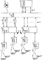
図1は本発明のPTT一点対多点私設通信ネットワーク("PTT私設ネットワーク")を内部に構築できる一実施の形態の電話システムの構成要素を示すものである。図1を参照すると、本実施の形態の電話システムは、公衆電話網(PSTN)10と、CDMAセルラー通信システム14と、アナログセルラ通信システム(AMPS)18とを有している。CDMAシステム14は、CDMAに適合している移動無線電話("CDMAモバイル")22及び24にサービスを提供する。一方、AMPSシステム18は、AMPSに適合している移動無線電話("AMPSモバイル")28及び30のユーザーとの通信を容易にする。複数のT1チャンネル44を介してPSTN10に接続されたネットワーク呼出管理装置40は、後述するように、図1の実施形態の電話システム内において対応する複数の会員ユーザー間の私設通信ネットワークを形成するものである。
[Detailed Description of Preferred Embodiment]
I. Configuration of PTT Private Network FIG. 1 shows components of a telephone system according to an embodiment capable of constructing a PTT point-to-multipoint private communication network (“PTT private network”) of the present invention. Referring to FIG. 1, the telephone system of the present embodiment includes a public telephone network (PSTN) 10, a CDMA
この私設通信ネットワークは、CDMA及びAMPSセルラシステム14及び18の一方或いは両方からのサービスを受ける会員ユーザーを含むことができ、かつ/もしくは電話48のような修正された地上回線電話を通じてPSTN10に直接接続された一人もしくはそれ以上の会員ユーザーを含むことができる。CDMA及びAMPSセルラーシステムは、図1の実施の形態内に組み込まれているように示したが、本発明の教示は、例えば移動通信用広域システム(GSM)及び時分割多元接続(TDMA)のような他のセルラー空中インターフェース規格にも関係が有るということを理解されたい。本発明の作動原理を論ずる前に、図1に示したCDMA及びAMPSセルラー通信システム14及び18の構成要素について簡単に説明する。
This private communications network may include member users receiving services from one or both of CDMA and AMPS
CDMAセルラー通信システム14は、複数のセルを有している。これらのセルのうちの2つは、セルサイト(すなわち"基地局")56及び58を有するものとして図1に示してある。各セルは、多数のセクタに区分されている。所定のセクタ内におけるCDMAモバイル22及び24との通信は、そのセクタにわたる無線到達範囲を提供するセルサイト送受信器によってなされる。基地局56及び58は、各CDMAモバイル内の無線送受信器とPSTN10との通信を可能とする信号を受信及び送信するように動作する。CDMAシステム14においては、データパケットが基地局56及び58とCDMAモバイル22及び24との間の情報の空中交換に利用されている。
The CDMA
電話の呼出は、セルサイト基地局56及び58によってCDMAモバイル22及び24とCDMA移動交換センター(MSC;mobile switching center)60との間の経路を決定される。このCDMA移動交換センター(MSC)60は、一般には、移動電話交換局(図示しない)内に設けられている。MSC60の主たる目的は、CDMAモバイル22及び24とPSTN10との間の音声通路接続を提供することにある。このために、MSC60は、適当なCDMA基地局56あるいは58によってMSCモデム62とCDMAモバイル22及び24との間のデータを評価するような機能を実行する。また、MSC60は、PSTN10から呼出を受けるとCDMAモバイルをページングし、呼出を複数のT1チャンネル64を介して利用可能なPSTN回線に切り換えるような他の作業も実行する。MSCモデム62の組は、CDMAモバイル22及び24から受信したデジタル情報信号をPSTN10を介して伝達するのに適したアナログ信号に変換し、またPSTN10からのアナログ信号をCDMAモバイル22及び24に引き続き送られるデジタル信号に変換する。
Phone calls are routed between
AMPSセルラ通信システム18もまた、多数のセルを有している。これらのセルのうちの2つは、セルサイト基地局70及び72を有するものとして図1に示してある。各セルは、多数のセクタに区分されている。所定のセクタ内におけるAMPSモバイル28及び30との通信は、そのセクタにわたる無線到達範囲を提供するセルサイト送受信器によってなされる。電話の呼出は、セルサイト基地局70及び72によってAMPSモバイル28及び30とAMPS移動交換センター(MSC)76との間の経路を決定される。このAMPS移動交換センター(MSC)76は、複数のT1チャンネル80を介してPSTN10に接続されている。
The AMPS
II.PTT私設ネットワークの作用
さて、本発明のPTT私設ネットワークの作用を説明するにあたり、図2に移って、一実施の形態のネットワーク呼出管理装置40のブロック線図を参照する。各会員ユーザーに関連付けられている地上回線あるいはセルラ電話がネットワーク呼出管理装置40と協働すべくどのように構成されているかを、以下に図3〜図5を参照して説明する。以下において、修正された地上回線電話48、AMPSモバイル28及び30,CDMAモバイル22及び24からネットワーク呼出管理装置40へのPSTN10を介する通信リンクは"逆リンク"の用語を用いる。ネットワーク呼出管理装置40によって作動中の会員ユーザーとして現在指定されている会員ユーザーに関連付けられている逆リンクは、有効な音声もしくはデータ情報を運ぶ逆リンクのうちの一つだけであると仮定する。他の全ての逆リンクは、信号情報をネットワーク呼出管理装置40に供給するために利用できる。ネットワーク呼出管理装置40から各会員ユーザーへのPSTN10を介する"順リンク"の各々は、作動中の会員ユーザーによって供給される音声あるいはデータ情報を運ぶ。以降で述べるように、ネットワーク呼出管理装置40は作動会員を新たに認識する毎に再形成される。このような再形成の結果、逆リンクにおける新たに認識された作動中の会員ユーザーからの音声あるいはデータ情報が、他の全ての会員ユーザーに関連付けられている順リンク(以前の作動会員ユーザーの順リンクを含む)に供給される。
II. Operation of PTT Private Network Now, the operation of the PTT private network of the present invention will be described with reference to a block diagram of the network
ネットワーク呼出管理装置40はネットワークコントローラ(ネットワーク制御装置)90を有しており、このネットワークコントローラ90には最初(first)のPTT私設ネットワークの会員ユーザーに関連付けられている少なくとも1つの電話番号リストが記憶されている。最初にPTT私設ネットワークへアクセスしたい場合には、呼出側の会員ユーザーは、第1のPTT私設ネットワークを識別するアクセスナンバーをダイヤルする。また、ネットワークコントローラ90は、会員ユーザーの他のリストも記憶することができる。各リストは、固有のアクセスナンバーに関連付けられているとともに、別個のPTT私設ネットワークを規定するものである。
The network
ネットワーク呼出管理装置40は、構内交換機(PBX)システムとしてPSTN10に現れるように設計されている。従って、呼出側の会員ユーザーによってなされた呼出は、T1チャンネル44のいずれか一つで受信される。これに関連して、呼出側の会員ユーザーに関連付けられているT1チャンネル44と複数のネットワーク管理モデム98の一つとの間を接続するために電話ネットワーク(T1)インターフェース92が設けられている。以降で述べるように、このT1インターフェース92は、また、他の様々なネットワーク管理モデム98の一つを他の会員ユーザーに関連付けられているT1チャンネル44の一つに接続する役割を果たす。
The
呼出側の会員ユーザーがCDMAセルラーシステム14によってサービスを受ける場合には、到来する呼出を受信するT1チャンネル44に接続されたネットワーク呼出管理モデム98'が呼出に割り当てられたMSCモデム62(図1)の一つと同期すると、電話接続が確立される。地上回線電話あるいはAMPSセルラー電話を有する呼出側会員ユーザーに対しても、会員ユーザーの電話内の内部モデム(図3A及び図4)及び到来する呼出を受信するネットワーク管理モデム98'が同期すると、同様な電話接続が確立される。本実施形態において、ネットワーク管理モデム98は、例えば、空中情報伝送に特に良く適したいわゆる"AMPSモデム"を有している。
When the calling member user is serviced by the CDMA
会員ユーザーからT1チャンネル44の一つを通じてPTT私設ネットワークが到来する呼出を受信すると、T1インターフェース92は、呼出をする間にダイヤルされたアクセスナンバーを決定するために標準的な技術を用いる。所定のPTT私的ネットワークに対応するこのようなダイヤルされたアクセスナンバーは、T1インターフェース92によってネットワークコントローラ90に伝えられる。また、T1インターフェース92は、呼出側会員ユーザーに関連付けられているT1チャンネル44を利用可能なネットワーク管理モデム(例えば、ネットワーク管理モデム98')に接続する。モデムの同期が一旦行われると、ネットワークコントローラ90は、呼び出されたアクセスナンバーに相当することが認識されているPTT私設ネットワークにおいて呼出側ユーザーが会員であることを証明するために用いられる認証情報を送るように呼出側ユーザーに要求する。会員であることの確認が得られると、ネットワークコントローラ90は、T1インターフェース92もしくは選択されたネットワーク管理モデム98に対して、認識されたPTT私設ネットワークの残りの会員ユーザーのページングを開始するように指令する。別の実施の形態として、T1インターフェース92は、E1インターフェースあるいは他の様々なデジタルまたは"PBXタイプ"のインターフェースであっても良いことに留意すべきである。
Upon receiving an incoming call from a member user through one of the
認識されたPTT私設ネットワークの他の会員ユーザーのうちの最初の者が呼出ネットワーク管理モデム98或いはT1インターフェース92によって発されたネットワークページ(すなわち、電話呼出)に応答すると、上記で説明したタイプと同様のモデム同期処理が再び生じる。特に、呼出される会員ユーザーがAMPSあるいは地上回線電話によりサービスを受けている場合には、呼出される会員ユーザー電話(図3A及び図4)内部のモデムとネットワーク管理モデム98の一つとの間のモデム同期が生じる。呼出される会員ユーザーがCDMAセルラシステム14によりサービスを受けている場合には、呼出側のネットワーク管理モデム98とMSCモデム62(図1)の一つとの間のモデム同期が生じる。MSCモデム62は、MSC60に物理的に接近している必要はなく、電話システムの下部構造(infrastructure)内のどこかに配置されていれば良いことを理解されたい。
When the first of the other member users of the recognized PTT private network responds to a network page (ie, a telephone call) issued by the call
呼出側のネットワーク管理モデム98がこのような同期を行うと、接続信号発生する。この接続信号は、ネットワークコントローラー90によって検出される。ネットワークコントローラー90は、次いで、呼出される側のネットワーク管理モデム98'に対して、認識されたPTT私設ネットワークのアクセスナンバーを最初にダイヤルした会員ユーザーに接続信号を送るように指示する。また、ネットワークコントローラーは、PTT私設ネットワークの証明された参加会員ユーザーの各々に、現在参加している会員ユーザーのリストを定期的に送ることもできる。このリストは、各証明されたユーザーの電話に表示される。
When the call-side
PTTコントローラ104は、認識されたPTT私設ネットワークに参加している二人もしくはそれ以上の数の会員ユーザー間の会話あるいはデータ伝送の特典を与えるために設けられている。特に、PTTコントローラー104は認識されたPTT私設ネットワークの会員ユーザーに関連付けられている地上回線あるいはセルラ電話によって発生するPTT要求信号("PTT要求")に応答する。PTTスイッチの手動操作に応答してあるいは会員ユーザーの音声作動の検出に応答して、各々のPTT要求が会員ユーザーの電話において発生する。所定の会員ユーザーからのPTT要求は、それに割り当てられたモデム98によって検出される。モデム98は、PTT信号をPTTコントローラー104に与える。
The
一実施の形態では、PTTコントローラ104は、その前の作動中の会員ユーザーによって解放されたネットワーク通話権に続いて受信した最初のPTT要求を送った一人を現在の作動中の会員ユーザーとして指定する。手動式のPTT信号発生の場合には、話者の電話のPTTスイッチの接続を開放することによって、ネットワーク通話権がその前の作動中の会員ユーザーによって放棄される。音声作動式のPTT信号発生の場合には、ネットワーク通話権は、予め設定された持続時間の中断の発生によって放棄される。
In one embodiment, the
別の実施の形態では、現在の作動中の会員ユーザーによってネットワーク通話権が放棄される前に受信されたPTT要求は順番付けられる。現在の作動中の会員ユーザーがその後ネットワーク通話権を放棄すると、順番付けられていたPTT要求は、次の現在の作動中の会員ユーザーを決定するために予め設定された基準に応じて評価される。このような予め設定された基準には、たとえば、会員ユーザーの優先順位や順番付けられている要求の受信順位が含まれる。 In another embodiment, PTT requests received before the network call right is relinquished by the currently active member user are ordered. When the currently active member user subsequently relinquishes the network call right, the ordered PTT request is evaluated according to preset criteria to determine the next current active member user . Such preset criteria include, for example, the priority order of member users and the reception order of ordered requests.
ネットワーク呼出管理装置40は、受信したPTT要求に基づいて新たな作動中の会員ユーザーを選択するために他の技術を用いることもできる。例えば、所定のPTT私設ネットワークの各会員ユーザーは、そのネットワーク内での相対的な優先順位を付与され得る。この場合、現在の作動中の会員ユーザーよりも優先順位の高い会員ユーザーからPTT要求が受信されると、ネットワーク呼出管理装置40は、現在の作動中の会員ユーザーの通話権を取り上げ、優先順位が高い会員ユーザーにネットワーク通話権を与える。また、緊急時にネットワーク通話権を得る手段として、各会員ユーザーが、ネットワーク呼出管理装置40に記憶されている規定された範囲内においてその優先順位を変更できるようにすることも可能である。
The
新たな作動中の会員ユーザーが、受信されたPTT要求に基づいてPTTコントローラ104によって認識された後は、PTTコントローラ104は、多重スイッチを形成し、もっぱら現在の作動中の会員ユーザーに関連付けられているモデム98からの逆リンク音声あるいはデータ情報(rverse link voice ordata information)を受け取るように多重スイッチ110を配列する。すなわち、他のモデム98のそれぞれからの逆リンク情報は、多重スイッチ110によって無視される。なお、モデム98のそれぞれは、残りの(すなわち、非作動)会員ユーザーに割り当てられている。また、PTTコントローラー104は、多重スイッチ110を配列し、新たに認識された作動中の会員ユーザーから受け取った逆リンク情報を各非作動中の会員ユーザーに関連付けられているモデム98に供給する。PTT要求は非作動中の会員ユーザーの逆リンクでのみ伝達されるので、このようなPTT要求は、作動中の会員ユーザーからの逆リンク情報の受信に影響を与えない。
After a new active member user is recognized by the
各PTT私設ネットワークの順リンクは、名目上作動中の会員ユーザーからの音声あるいはデータ情報を他の全ての会員ユーザーに運ぶために用いられるが、ネットワークコントローラー104も、作動中の会員ユーザーによる情報伝達における休止あるいはギャップの間にシステム状況情報を順リンクで伝達することができる。一実施の形態では、このシステム状況情報には次のものが含まれる。
(i)PTT私設ネットワークの適格な会員ユーザー(電話番号、名前、優先順位)
(ii)PTT私設ネットワークに現在参加している会員ユーザー(電話番号、名前、優先順位)
(iii)現在の作動中の会員ユーザー(電話番号、名前、優先順位)
(iv)PTTトーン要求をPTTコントローラー90に供給し、順序付けられている会員ユーザー(電話番号、名前、優先順位、要求の順位)
Each PTT private network forward link is used to carry voice or data information from a nominally active member user to all other member users, but the
(i) Eligible member users of PTT private network (phone number, name, priority)
(ii) Member users who are currently participating in the PTT private network (phone number, name, priority)
(iii) Currently active member users (phone number, name, priority)
(iv) Supplying PTT tone requests to the
このネットワーク状況情報は、会員ユーザーに関連付けられている電話で受信されるとともに表示される。次のセクションでは、本発明のPTT私設ネットワーク内での使用に適したPTTデュアルモード電話の実施例について説明する。 This network status information is received and displayed on the telephone associated with the member user. The next section describes an embodiment of a PTT dual mode telephone suitable for use in the PTT private network of the present invention.
III.地上回線及びセルラーPTTデュアルモード電話
図3Aを参照すると、伝達部140及び受信部142から成る地上回線PTTデュアルモード電話のブロック図が示されている。図3Aのデュアルモード電話の伝達部140は、入力スイッチ148を極150側に倒すと、入力マイクロフォン154をPSTN10に接続され、標準的な電話操作ができるように構成されている。PTT私設ネットワーク内でのPTT操作ができるように伝達部140を構成する場合には、入力スイッチ148は極158側に倒される。同様に、受信部142は、受信スイッチ162が極168側に倒されたときに、標準的な電話操作ができるように設定され、受信スイッチ162が極166側に倒されたときに、PTT操作ができるように設定されている。
III. Terrestrial Line and Cellular PTT Dual Mode Telephone Referring to FIG. 3A, a block diagram of a terrestrial line PTT dual mode telephone comprising a
PTT操作中は、マイクロフォン154からの音声情報はスイッチ148によってコーデック172に連結される。コーデック172は、スイッチ148に接続された周辺機器(図示せず)からのこのアナログ音声情報あるいはデータ情報をボコーダ176に供給されるパルスコード変調(PCM)波形に変換するために配置されている。一実施の形態では、ボコーダ176は、EIA(エレクトロニクス工業協会)/TIA(遠距離通信協会)の規格IS−96Aを満たすように実現化され、入力PCM波形を一連のボコーダーデーターパケットに変換する。これらのボコーダーデーターパケットは、マイクロプロセッサー178の第1入力に供給される。また、マイクロプロセッサ178は、PTTプロセッサー184に連結された第2入力及びモデム180に接続された出力を有する。PTTスイッチ188が関連付けられている会員ユーザーによって閉じられると、PTTプロセッサー184は、PTTデーターパケットをマイクロプロセッサー178の第2入力に供給する。マイクロプロセッサー178は、その後PTTデーターパケットをボコーダーデーターパケットと交互配置(interleave)し、その結果をモデム180に供給する。これにより、PTT操作中においてネットワーク管理モデム98の一つと同期化されるようになる。PTTプロセッサー184はマイクロプロセッサー178とは機能的に異なるものとして示されているが、これら両機能要素は単一のマイクロプロセッサーユニット内に組み込むこともできる。
During PTT operation, audio information from
受信部142は、モデム復調器192を有している。モデム復調器192は、PTTモード操作中、ネットワーク呼出管理装置40内で仲間ネットワーク管理モデム(companion network medem)98と同期化されるようになる。その仲間ネットワーク管理モデム98からの順リンク情報に応答して第2モデム192により発生されたボコーダーデーターパケットは、受信部のIS−96Aボコーダー196に供給される。ボコーダー196は、受信したボコーダーデーターパケットから順にPCM信号を発生する。この信号は、受信部のコーデック200によって使用される。コーデック200からのアナログ出力は、その後従来の電話スピーカー204に供給される。留意すべき点は、コーデック172、200によって成される機能は単一の装置によって達成され得るということである。同様に、ボコーダー176のエンコーディング機能は、単一の装置内においてボコーダ196のデコーディング機能と結合することができる。
The receiving
図3Aに示されるように、受信部142によってネットワーク管理装置40から受信したある情報は、信号ライン212を介してマイクロプロセッサー178に供給される。この情報は、マイクロプロセッサー178によって従来の表示装置214(たとえば、LCDスクリーン)へ供給されるべき種々のネットワーク状況データ(たとえば、他の関係する会員ユーザー、現在の作動中の会員ユーザーの識別データ)を含む。
As shown in FIG. 3A, certain information received from the
図3Bは、PTT私的ネットワーク内での暗号化通信を容易にするために修正された図3Aの地上回線PTTデュアルモード電話を示している。特に、図3Aの電話用の別の伝達部140'は、IS−96Aボコーダー176とマイクロプロセッサー178との間に介在された暗号モジュール210を有している。一実施の形態では、暗号モジュール210は、工業規格アルゴリズム、たとえば、データ暗号規格(DES)に基づいてボコーダーデーターパケットを暗号化する。同様に、別の受信部142'は、第2モデム192によって発生されたボコーダーデーターパケットからの暗号を除去するための暗号解読モジュール214を有している。再び留意すべき点は、コーデック172、200によって成される機能は単一の装置によって達成され得るということである。同様に、ボコーダー176のエンコーディング機能は単一の装置内においてボコーダー196のデコーディング機能と結合させることができる。さらに、暗号化モジュール210及び暗号解読モジュール214の機能も、単一の装置内において結合させることができる。暗号化通信に関係することのできるあるPTT私設ネットワークの全ての会員ユーザーに関連付けられている地上回線及びセルラー電話は、同様にこの種の暗号モジュール及び暗号解読モジュールが用いられる。
FIG. 3B shows the landline PTT dual mode telephone of FIG. 3A modified to facilitate encrypted communication within the PTT private network. In particular, another
図3Bの地上回線電話のユーザーが現在の作動中の会員ユーザーとして指定されると、マイクロプロセッサー178は、暗号化識別番号(I.D.)を発生し、ネットワーク呼出管理装置40へ伝達する。暗号化I.D.は、暗号モジュール210によって発生された暗号化情報の解読に使用される特別な"キー"と関連付けられる。ネットワーク呼出管理装置40は、暗号化I.D.を残りの非作動(すなわち、非通話)会員ユーザーに関連付けられている電話のそれぞれに多重付与(multicast)する。各非作動中の会員ユーザーは、暗号解読モジュール214に類似した暗号解読モジュールを有する。各暗号解読モジュールは、基本的に各暗号化I.D.に関連付けられている暗号解読キーを認識するルックアップテーブルを有する。したがって、各非作動中の会員ユーザーは、与えられた暗号化I.D.を受信することによって、現在の作動中の会員ユーザーからの暗号化情報を暗号解読することができる。
When the user of the landline telephone of FIG. 3B is designated as a currently active member user, the
図4を参照すると、伝達部240及び受信部242から成るAMPSデュアルモードPTT電話のブロック図が示されている。図4のAMPSデュアルモードPTT電話の伝達部240は、入力スイッチ248を極250側に倒すと、入力マイクロフォン254がAMPS送信機255に接続され、標準的な電話操作ができるように構成されている。PTT私設ネットワーク内でのPTT操作ができるように伝達部240を構成する場合には、入力スイッチ248は極258側に倒される。同様に、受信部242は、受信スイッチ262が極266側に倒されるときに、標準的な電話操作ができるように設定され、受信スイッチ262がポール極268側に倒されたときに、PTT操作ができるように設定されている。
Referring to FIG. 4, a block diagram of an AMPS dual mode PTT telephone consisting of a
PTT作動中は、マイクロフォン254からの音声情報は、スイッチ248によってコーデック272に接続される。コーデック272は、このアナログ音声情報をIS−96Aボコーダ276に供給されるパルスコード変調(PCM)波形に変換する。結果として発生するボコーダーデータパケットは、選択的に暗号モジュール278により暗号化される。暗号化を望まないときは、ボコーダーデータパケットは、PTTプロセッサー284からのPTTパケットと交互配置するためにマイクロプロセッサー279に供給される。再度、PTTパケットは、PTTスイッチ288の操作に応答してPTTプロッセッサー284で発生される。インターリーブされたボコーダデータ及びPTTパケットは、送信経路モデム280によって処理され、AMPS基地局70あるいは72に送信するためのAMPS送信機255に供給される。他の実施の形態では、周辺装置(図示せず)からのデータ情報は、暗号モジュュール278あるいは直接にマイクロプロセッサー279に供給することができる。
During PTT operation, audio information from
受信部242は、ネットワーク呼出管理装置40によって供給される順リンク情報を受信するためのAMPS受信機291を有している。AMPS受信機291からのアナログ出力は、受信経路モデム292に連結される。モデム292は、PTTモードで動作している間、ネットワーク管理モデム98と同期する。受信経路モデム292によって発生されるボコーダデータパケットは、暗号化PTT私的通信の期間中、解読モジュール294に供給される。暗号化がなされないときは、ボコーダデータパケットは、受信部コーデック300で用いられるPCM信号を生成するために受信部ボコーダ296によって処理される。コーデック300のアナログ出力は、従来からある電話スピーカー304に供給される。暗号化がなされるときは、私設ネットワーク状態情報とネットワーク管理装置40から受信した同種の情報は、暗号解読されるとともに、信号線212を通ってマイクロプロセッサー178に供給される。
The receiving unit 242 has an
図3A及び図3Bを参照して議論したように、再び、コーデック272及び300によってなされる機能を単一のデバイスで行うことができることに留意すべきである。同様に、ボコーダ276の符号化機能は、ボコーダ296の復調機能と一つのデバイスで行うことができる。さらに、暗号化モジュール278と暗号解読モジュール294の機能もまた、一つのデバイスに結合することができる。
It should be noted that again, the functions performed by
図5は、PTT私設ネットワーク内で使用するために形成されたCDMAセルーラ電話のブロック図を示す。図5のCDMAセルラー電話は、CDMA送信部340とCDMA受信部342からなる。PTT作動中、マイクロフォン354からの音声情報は、パルスコード変調(PCM)波形を生成するコーデック372に供給される。PCM波形は、ボコーダ376に供給され、ボコーダ376は次いで、暗号モジュール378における選択的な暗号化のためのボコーダデータパケットを発生する。暗号化を望まないときは、ボコーダデータパケットはマイクロプロセッサ379に送られて、PTTプロセッサー384からのPTTパケットと交互配置される。この場合も、PTTパケットは、PTTスイッチ388の動作に応答してプロセッサ384で生成される。交互配置されたボコーダーデータパケットとPTTパケットとは、マイクロプロセッサ379によってCDMA送信機355に供給される。
FIG. 5 shows a block diagram of a CDMA cellular telephone configured for use in a PTT private network. The CDMA cellular phone shown in FIG. 5 includes a
CDMA受信部342は、CDMA受信機392を有している。CDMA受信機392は、ネットワーク呼出管理装置40からの順リンク情報に応答してボコーダーデータパケットを発生する。ボコーダーデータパケットは暗号化されたPTT私設通信の間、暗号解読モジュール394に供給される。暗号化がなされないときは、ボコーダーデータパケットは、CDMA受信部コーデック400で用いられるPCM信号を生成するためにCDMA受信部ボコーダ396によって処理される。CDMA受信部コーデック400のアナログ出力は、従来からある電話スピーカー404に供給される。コーデック372及び400によってなされる機能を単一の装置で行うことができ、同様に、ボコーダ376及びボコーダ396の機能もまた一つの装置で果たすことができる。さらに、暗号モジュール378と暗号解読モジュール394の機能も、また、一つの装置内でに結合することができる。
The CDMA receiver 342 has a
IV.アナログPTT私設ネットワーク
図6は、信号の通信にアナログトーンを用いるPTT私設ネットワーク内で用いるために設計されたネットワーク呼出管理装置450の機能ブロック図を示す。ネットワーク呼出管理装置450は、ネットワークコントローラー490を有する。ネットワークコントローラー490内には、対応するPTT私設ネットワークの会員ユーザーと関連付けられている一つあるいはそれ以上の電話番号リストが記憶されている。あるPTT私設ネットワークにアクセスしたい時は、呼出側会員ユーザーは、そのPTT私設ネットワークを識別するアクセスナンバーをダイアルする。
IV. Analog PTT Private Network FIG. 6 shows a functional block diagram of a network call manager 450 designed for use in a PTT private network that uses analog tones for signal communication. The network call management device 450 has a
ネットワーク呼出管理装置450は、構内交換機(PBX)システムとしてPSTN10に現れるように設計されている。従って、呼出側の会員ユーザーによってなされた呼出は、複数のネットワーク管理トーン検出器498のうちの一つと関連付けられているT1チャンネル44で受信される。到来する呼出を受信するトーン検出器498'は、出力線500'で検出信号を出力する。出力線500'の検出信号は、ネットワークコントローラー490で感知される。そして、ネットワークコントローラー490は、呼出側のPTTユーザーを認証するために、呼出されたネットワーク管理トーン検出器498'で検出されたトーンシーケンス(tone sequence)を詳しく調べる。一旦、ダイアルされたアクセスナンバーがネットワークコントローラー490によって認識され、また関連するPTT私設ネットワークが識別されると、ネットワークコントローラー490は、標準電話ネットワーク手続きを使用して残りのT1チャンネル44により、識別されたPTT私設ネットワークの会員ユーザーのページングが開始される。識別されたPTT私設ネットワークの他の会員ユーザーの一番目がネットワーク呼出に応答したことを検知すると、ネットワークコントローラー490は、識別されたPTT私設ネットワークのアクセスナンバーを最初にダイアルした会員利用者にトーンの形態の接続信号を送る。それによって、呼出側の会員ユーザーに、識別されたPTT私設ネットワークに少なくとも一人の他の会員ユーザーが参加していることを示す。
Network call manager 450 is designed to appear on
PTTコントローラー504は、識別されたPTT私設ネットワークに参加している二人又はそれ以上の会員ユーザーの中から通話権を与えるための準備をする。特に、PTTコントローラー504は、識別されたPTT私設ネットワークの会員ユーザーに関連付けられている電話によって発生されたアナログトーン('PTTトーン要求')の一つあるいは結合された形のPTT要求信号に応答する。各PTTトーン要求は、PTTスイッチの手段操作に応答して、あるいは会員ユーザーの音声作動を検知することに応答して、会員ユーザーの電話で発生される。ある会員ユーザーからのPTTトーン要求は、それに割り当てられたトーン検出器498で検出される。そして、トーン検出器498は、PTT要求信号をPTTコントローラ504に出力線500の一つにより供給する。実施の形態では、PTTコントローラー504は、PTTコントローラ104(図2)に関係した部分で既に記述した方法によって、要求している会員利用者の中から通話権を割り当てる働きをする。
The
新しい作動中の会員ユーザーは、PTTトーン要求の受信に基づいてPTTコントローラー504によって識別される。PTTコントローラー504は、現在の作動中の会員ユーザーに関連付けられたT1チャンネル44からの逆リンク音声あるいはデータ情報を排他的に受け取るためにマルチキャストスイッチ(multicast switch)510を形成する。すなわち、それぞれ残りの(すなわち、非作動中の)会員ユーザーの1つに割り当てられた他のT1チャンネルの各々からの逆リンク情報は、マルチキャストスイッチ110によってマルチキャストされない。また、PTTコントローラー504は、新しく認識された作動中の会員ユーザーから受け取った逆リンク情報を各非作動中の会員ユーザーと対応付けられているT1チャンネルに供給するようにマルチキャストスイッチ504を形成する。PTTトーン要求は、非作動中の会員ユーザーの逆リンクにのみ送信されるため、そのようなPTTトーン要求は、作動中の会員ユーザーからの逆リンク情報の受け取りを妨害しない。
A new active member user is identified by the
各PTT私設ネットワークの順リンクは、一般的に、作動中の会員ユーザーからの音声あるいはデータ情報を全ての他の会員ユーザーへ運ぶために用いられるため、ネットワークコントローラー504は、作動中の会員ユーザーによる情報伝送の中止あるいはギャップの期間に順リンクにシステム状態情報を伝送する。
Because the forward link of each PTT private network is typically used to carry voice or data information from an active member user to all other member users, the
実施の形態では、このシステム状態情報は以下のものを含む。
(i)PTT私設ネットワークの適格な会員ユーザー(電話番号、名前、優先順位)
(ii)PTT私設ネットワークに現在参加している会員ユーザー(電話番号、名前、優先順位)
(iii)現在作動中の会員ユーザー(電話番号、名前、優先順位)
(iv)PTTトーン要求をPTTコントローラー490に供給し、順序付けられている会員ユーザー(電話番号、名前、優先順位、要求の順位)
In an embodiment, this system state information includes:
(i) Eligible member users of PTT private network (phone number, name, priority)
(ii) Member users who are currently participating in the PTT private network (phone number, name, priority)
(iii) Currently active member users (phone number, name, priority)
(iv) Supplying PTT tone requests to the
このような情報は、各会員ユーザーの電話内で検知可能なトーンのシーケンスあるいはトーンの結合を用いて送信されることができる。種々のPTT私設ネットワーク情報(すなわち、会員ユーザーリスト、優先順位)、そしてネットワーク呼出管理装置450からの関連するトーンあるいはトーンの結合の受信により表示のために取り戻された特別な登録は、各会員ユーザーの電話内に格納される。この点に関して、ネットワーク呼出管理装置450によって統合されたPTT私設ネットワーク内で利用するために構成された地上電話回線を、図7を参照して以下に説明する。 Such information can be transmitted using a sequence of tones or a combination of tones that are detectable within each member user's phone. A special registration retrieved for display by receipt of various PTT private network information (ie, member user list, priority) and associated tones or combinations of tones from the network call manager 450 is available to each member user. Stored in the phone. In this regard, a terrestrial telephone line configured for use in a PTT private network integrated by the network call manager 450 will be described below with reference to FIG.
図7には、アナログトーンを用いて通信するように設計された送信部及び受信部540及び542を有する地上回線PTT電話のブロック図を示している。PTT動作中、入力スイッチ548は、通常は、入力マイクロフォン554からPSTNに音声情報を結合するために、PTTプロセッサー552によって極550側ににセットされる。しかしながら、PTTスイッチ560が会員ユーザーによって接続された時は、PTTプロセッサー552は、スイッチ548を極562側にセットされる。これにより、トーン発生器566が使用可能となる。トーン発生器566によって発生されたPTTトーン要求の許可は、ネットワーク呼出管理装置450にPSTNを介して送信される。
FIG. 7 shows a block diagram of a terrestrial PTT telephone having a transmitter and
受信部542は、スピーカー568と、PTTモード動作中ネットワーク呼出管理装置450によって送信されるアナログトーンあるいはその結合を検出する内部トーン検出器570とを有する。これらのトーンあるいはトーンの結合は、図7のPTT電話に様々な状態情報及び制御情報を運ぶために用いられる。実施の形態では、この情報は、次のものを含む。
(i)現在作動中の会員ユーザーの識別(名前、優先順位)
(ii)PTT電話に関連付けられている会員ユーザーが通話権を与えられていることの表示
(iii)PTT電話に関連付けられている会員ユーザーの通話権がさらに高い優先順位を有する会員ユーザーのために取り消されることの通知
(iv)PTT私設ネットワークに現在参加している会員ユーザーの識別
The receiving unit 542 includes a
(i) Identification of currently active member users (name, priority)
(ii) Indication that the member user associated with the PTT phone has been given the right to call
(iii) Notification that the calling rights of the member user associated with the PTT phone will be revoked for a member user with a higher priority
(iv) Identification of member users currently participating in the PTT private network
各トーンあるいはトーン結合は、表示プロセッサー574内に記憶されている他のメッセージや連続文字と関連付けられる。検出された各トーンあるいはトーンの応答して、表示プロセッサー574は、関連付けられているメッセージを英数字ディスプレイ578に供給する。上で列挙された状態情報及び制御情報は、単に例示しただけであり、他の実施例では他のタイプの情報をネットワーク管理装置によってPTT電話に供給するようにしてもよい。
Each tone or tone combination is associated with another message or sequence of characters stored in
好ましい実施の形態についての先の説明は、当業者が本発明を作りあるいは使用することができるように提供したものである。前述した実施の形態への様々な改良は、当業者に容易に明らかであり、またここで定義されている一般的な原理を他の実施例に適用するのに発明的才能は必要ではない。したがって、本発明はここに示された実施の形態に制限されるものではなく、ここに示した原理と新しい特色に一致して広範囲にわたり提供されるものである。 The previous description of the preferred embodiments is provided to enable any person skilled in the art to make or use the present invention. Various modifications to the embodiments described above will be readily apparent to those skilled in the art, and no inventive talent is required to apply the general principles defined herein to other embodiments. Accordingly, the present invention is not limited to the embodiments shown herein, but is provided in a broad range consistent with the principles and new features shown herein.
Claims (11)
前記交換電話ネットワークの複数のチャンネルにより前記複数の会員ユーザーの各々との電話接続を確立するための電話ネットワークインターフェースを有し、
前記電話ネットワークインターフェースと接続され、前記ネットワークインターフェースにより前記複数のチャンネルの1つで受信した情報信号を前記電話ネットワークインターフェースを介して前記複数のチャンネルの他のチャンネルに供給するスイッチマトリックスを有し、
前記複数のチャンネルの選択された1つで受信した通話要求信号に応答して前記スイッチマトリックスを形成するための制御装置を有するネットワーク呼出管理装置であって、
前記複数の会員電話機は、前記会員ユーザーの一人によって提供された情報信号を暗号化した暗号化信号を発生する手段を有し、前記暗号化信号は前記複数のチャンネルの対応する1つで送信されるネットワーク呼出管理装置。 A network call management device for facilitating communication between a plurality of member user telephones in a communication system in which a user communicates via an exchange telephone network,
A telephone network interface for establishing a telephone connection with each of the plurality of member users via a plurality of channels of the switched telephone network;
A switch matrix connected to the telephone network interface and supplying an information signal received on one of the plurality of channels by the network interface to another channel of the plurality of channels via the telephone network interface;
A Rene Ttowaku call management apparatus having a control device for forming said switch matrix in response to a call request signal received by a selected one of said plurality of channels,
The plurality of member telephones have means for generating an encrypted signal obtained by encrypting an information signal provided by one of the member users, and the encrypted signal is transmitted on a corresponding one of the plurality of channels. Network call management device.
プロセッサに接続されたボコーダーモジュールを有し、該ボコーダ−モジュールは入力信号をデジタル処理してパケット化された情報信号にするためのものであり、
所定のユーザ入力に応答して通話要求信号を発生するための手段を有し、
前記プロセッサは前記通話要求信号を前記パケット化された情報信号と交互配置する手段を構成しており、
前記パケット化された情報信号を暗号化するための手段を有する会員ユーザ電話機。 A member user phone for use by member users of a multi-party communication system,
A vocoder module connected to a processor, the vocoder module for digitally processing an input signal into a packetized information signal;
Means for generating a call request signal in response to a predetermined user input;
The processor comprises means for interleaving the call request signal with the packetized information signal;
A member user telephone having means for encrypting the packetized information signal .
ネットワーク呼出管理装置と、各々が前記複数の会員ユーザーの一人と関連付けられている前記交換電話ネットワークの複数の電話チャンネルの各々との間の電話接続を確立するステップと、Establishing a telephone connection between a network call management device and each of a plurality of telephone channels of the switched telephone network each associated with one of the plurality of member users;
前記会員ユーザーの中の作動中の一つから前記複数の電話チャンネルの選択された1つにより前記ネットワーク呼出管理装置で受信した情報信号を、前記会員ユーザーの他の一つに前記複数の電話チャンネルの他の1つにより供給するステップと、The information signal received by the network call management device according to a selected one of the plurality of telephone channels from one of the member users in operation is transmitted to the other telephone channel of the member user. Supplying by one of the other,
前記交換電話ネットワークを介して前記ネットワーク呼出管理装置に送信するために前記複数の会員ユーザーと関連付けられている複数の電話機で通話要求信号を発生するステップと、Generating a call request signal at a plurality of telephones associated with the plurality of member users for transmission to the network call management device via the switched telephone network;
前記ネットワーク呼出管理装置で受信した前記通話要求信号に基づいて前記作動中の会員ユーザーを選択するステップと、Selecting the active member user based on the call request signal received at the network call management device;
前記作動中の会員ユーザーと関連付けられている前記複数の電話機の1つ内で発生した情報信号を暗号化するステップと、Encrypting an information signal generated in one of the plurality of telephones associated with the active member user;
暗号化された情報信号を前記ネットワーク呼出管理装置に送信するステップと、Transmitting an encrypted information signal to the network call management device;
前記会員ユーザーの他の一つと関連付けられている前記複数の電話機の1つで前記ネットワーク呼出管理装置から受信した暗号化された情報信号を暗号解読するステップとを備える方法。Decrypting an encrypted information signal received from the network call management device at one of the plurality of telephones associated with another one of the member users.
Applications Claiming Priority (1)
| Application Number | Priority Date | Filing Date | Title |
|---|---|---|---|
| US08/595,566 US5912882A (en) | 1996-02-01 | 1996-02-01 | Method and apparatus for providing a private communication system in a public switched telephone network |
Related Parent Applications (1)
| Application Number | Title | Priority Date | Filing Date |
|---|---|---|---|
| JP9527825A Division JP2000504182A (en) | 1996-02-01 | 1997-01-29 | Method and apparatus for providing a private communication system in a public telephone network |
Publications (2)
| Publication Number | Publication Date |
|---|---|
| JP2008099328A JP2008099328A (en) | 2008-04-24 |
| JP4445005B2 true JP4445005B2 (en) | 2010-04-07 |
Family
ID=24383760
Family Applications (2)
| Application Number | Title | Priority Date | Filing Date |
|---|---|---|---|
| JP9527825A Pending JP2000504182A (en) | 1996-02-01 | 1997-01-29 | Method and apparatus for providing a private communication system in a public telephone network |
| JP2007324553A Expired - Fee Related JP4445005B2 (en) | 1996-02-01 | 2007-12-17 | Method and apparatus for providing a private communication system in a public telephone network |
Family Applications Before (1)
| Application Number | Title | Priority Date | Filing Date |
|---|---|---|---|
| JP9527825A Pending JP2000504182A (en) | 1996-02-01 | 1997-01-29 | Method and apparatus for providing a private communication system in a public telephone network |
Country Status (22)
| Country | Link |
|---|---|
| US (2) | US5912882A (en) |
| EP (1) | EP0878103B1 (en) |
| JP (2) | JP2000504182A (en) |
| KR (1) | KR100443781B1 (en) |
| CN (1) | CN1214842A (en) |
| AR (1) | AR005690A1 (en) |
| AT (1) | ATE320696T1 (en) |
| AU (1) | AU716936B2 (en) |
| BR (1) | BR9707264B1 (en) |
| CA (1) | CA2244929C (en) |
| DE (1) | DE69735478T2 (en) |
| ES (1) | ES2264156T3 (en) |
| FI (1) | FI119796B (en) |
| HK (1) | HK1017205A1 (en) |
| ID (1) | ID15870A (en) |
| IL (1) | IL125610A0 (en) |
| MY (1) | MY122360A (en) |
| NO (1) | NO316967B1 (en) |
| RU (1) | RU2178957C2 (en) |
| TW (1) | TW393848B (en) |
| WO (1) | WO1997028658A2 (en) |
| ZA (1) | ZA97795B (en) |
Families Citing this family (72)
| Publication number | Priority date | Publication date | Assignee | Title |
|---|---|---|---|---|
| US6389010B1 (en) * | 1995-10-05 | 2002-05-14 | Intermec Ip Corp. | Hierarchical data collection network supporting packetized voice communications among wireless terminals and telephones |
| GB9603582D0 (en) | 1996-02-20 | 1996-04-17 | Hewlett Packard Co | Method of accessing service resource items that are for use in a telecommunications system |
| US6195532B1 (en) * | 1996-06-28 | 2001-02-27 | At&T Wireless Srcs. Inc. | Method for categorization of multiple providers in a wireless communications service environment |
| US6799159B2 (en) * | 1998-02-02 | 2004-09-28 | Motorola, Inc. | Method and apparatus employing a vocoder for speech processing |
| US7522931B2 (en) * | 1998-06-05 | 2009-04-21 | Netnumber, Inc. | Method and apparatus for accessing a network computer to establish a push-to-talk session |
| US6144651A (en) * | 1998-07-17 | 2000-11-07 | Motorola, Inc. | Data transmission within a wireless communication system |
| US6188897B1 (en) | 1998-08-17 | 2001-02-13 | At&T Wireless Svcs. Inc. | Mobile station roaming in a multiple service provider area |
| WO2000044103A1 (en) * | 1999-01-20 | 2000-07-27 | Ericsson Inc. | Full-duplex radio-communication device with half-duplex functionality |
| US6360093B1 (en) * | 1999-02-05 | 2002-03-19 | Qualcomm, Incorporated | Wireless push-to-talk internet broadcast |
| US7746994B1 (en) * | 1999-09-28 | 2010-06-29 | Naxos Finance Sa | Method for managing information in a telephone and telephone for managing information |
| IL138097A0 (en) * | 2000-08-25 | 2003-06-24 | Rafael Armament Dev Authority | Method of managing a distributed communications system |
| US6801524B2 (en) | 2000-01-31 | 2004-10-05 | Sonim Technologies, Inc. | System for dispatching information packets and method therefor |
| BR0108899A (en) * | 2000-03-03 | 2005-10-18 | Qualcomm Inc | Method and apparatus for participating in group communication services in an existing communication system |
| EP2271170B1 (en) * | 2000-03-03 | 2012-09-05 | Qualcomm Incorporated | Method and apparatus for participating in group communication services in an existing communication system |
| US6477150B1 (en) * | 2000-03-03 | 2002-11-05 | Qualcomm, Inc. | System and method for providing group communication services in an existing communication system |
| US6944137B1 (en) * | 2000-03-24 | 2005-09-13 | Motorola, Inc. | Method and apparatus for a talkgroup call in a wireless communication system |
| US6308079B1 (en) * | 2000-03-24 | 2001-10-23 | Motorola, Inc. | Method and apparatus for a talkgroup call in a wireless communication system |
| KR100362928B1 (en) * | 2000-05-12 | 2002-11-29 | 박근서 | Wire/Wireless Conversion Telephone Exchange System |
| DE10046339C2 (en) * | 2000-09-19 | 2002-11-07 | Siemens Ag | Method of operating a communication system |
| US7408948B2 (en) | 2001-04-17 | 2008-08-05 | Nokia Corporation | Packet mode speech communication |
| US7386000B2 (en) | 2001-04-17 | 2008-06-10 | Nokia Corporation | Packet mode speech communication |
| US7890129B2 (en) | 2001-05-15 | 2011-02-15 | Eric Rosen | Method and apparatus for delivering information to an idle mobile station in a group communication network |
| US6963543B2 (en) * | 2001-06-29 | 2005-11-08 | Qualcomm Incorporated | Method and system for group call service |
| US20030078064A1 (en) * | 2001-10-22 | 2003-04-24 | Chan Victor H. | System and method for queuing talk requests in wireless dispatch system |
| US7778606B2 (en) * | 2002-05-17 | 2010-08-17 | Network Security Technologies, Inc. | Method and system for wireless intrusion detection |
| FI114358B (en) * | 2002-05-29 | 2004-09-30 | Nokia Corp | A method in a digital network system for controlling the transmission of a terminal |
| US8411594B2 (en) | 2002-09-20 | 2013-04-02 | Qualcomm Incorporated | Communication manager for providing multimedia in a group communication network |
| US7437162B1 (en) | 2003-02-10 | 2008-10-14 | Sprint Spectrum L.P. | Method and system for dynamically delivering a voice call as voice or data depending on data-mode of destination terminal |
| US7853250B2 (en) | 2003-04-03 | 2010-12-14 | Network Security Technologies, Inc. | Wireless intrusion detection system and method |
| US7603710B2 (en) | 2003-04-03 | 2009-10-13 | Network Security Technologies, Inc. | Method and system for detecting characteristics of a wireless network |
| KR20040094275A (en) * | 2003-04-30 | 2004-11-09 | 삼성전자주식회사 | Call setup method for push-to-talk service in cellular mobile telecommunications system |
| US20050032539A1 (en) * | 2003-08-06 | 2005-02-10 | Noel Paul A. | Priority queuing of callers |
| CN101077017B (en) * | 2003-11-19 | 2011-06-01 | 捷讯研究有限公司 | Systems and methods for facilitating instant communications over distributed cellular networks |
| US20050221852A1 (en) * | 2004-04-05 | 2005-10-06 | D Avello Robert F | Methods for controlling processing of inputs to a vehicle wireless communication interface |
| US20050221876A1 (en) * | 2004-04-05 | 2005-10-06 | Van Bosch James A | Methods for sending messages based on the location of mobile users in a communication network |
| US20050239486A1 (en) * | 2004-04-05 | 2005-10-27 | D Avello Robert F | Methods and systems for controlling communications in an ad hoc communication network |
| US20050222752A1 (en) * | 2004-04-05 | 2005-10-06 | Sokola Raymond L | Method for enabling communications dependent on user location, user-specified location or orientation |
| US20050222756A1 (en) * | 2004-04-05 | 2005-10-06 | Davis Scott B | Methods for displaying a route traveled by mobile users in a communication network |
| US20050221821A1 (en) * | 2004-04-05 | 2005-10-06 | Sokola Raymond L | Selectively enabling communications at a user interface using a profile |
| US7245898B2 (en) * | 2004-04-05 | 2007-07-17 | Motorola, Inc. | Programmable foot switch useable in a communications user interface in a vehicle |
| US7062286B2 (en) * | 2004-04-05 | 2006-06-13 | Motorola, Inc. | Conversion of calls from an ad hoc communication network |
| US20050221878A1 (en) * | 2004-04-05 | 2005-10-06 | Van Bosch James A | Method for entering a personalized communication profile into a communication user interface |
| US7792542B2 (en) * | 2004-07-16 | 2010-09-07 | Research In Motion Limited | Transmit channel policing system, device, and method |
| CN100359965C (en) * | 2004-07-27 | 2008-01-02 | 华为技术有限公司 | Implementation method for confirming effect of receiving PoC service |
| US7570630B1 (en) | 2004-08-02 | 2009-08-04 | Sprint Spectrum L.P. | Dialed-digit based determination of whether to originate a call as a circuit-switched call or a packet-switched call |
| JP2006101048A (en) * | 2004-09-29 | 2006-04-13 | Nec Corp | Ptt communication system, portable terminal device, and conversation start method used for them and program thereof |
| DE102004053597B4 (en) * | 2004-11-05 | 2008-05-29 | Infineon Technologies Ag | A method for automatically generating and / or controlling a telecommunications conference with a plurality of subscribers, telecommunication conference terminal and telecommunication conference server |
| GB0500483D0 (en) * | 2005-01-11 | 2005-02-16 | Nokia Corp | Multi-party sessions in a communication system |
| US7483708B2 (en) * | 2005-03-31 | 2009-01-27 | Mark Maggenti | Apparatus and method for identifying last speaker in a push-to-talk system |
| JP2006295460A (en) * | 2005-04-08 | 2006-10-26 | Ntt Docomo Inc | Speech object selection server apparatus, terminal, speech object selection system, and speech object selection method |
| WO2006137005A1 (en) * | 2005-06-24 | 2006-12-28 | Koninklijke Philips Electronics N.V. | Method and apparatus for semi-duplex communication in wireless communication system |
| WO2007010929A1 (en) * | 2005-07-20 | 2007-01-25 | Sanyo Electric Co., Ltd. | Mobile telephone unit, informing method, and program |
| US7873743B2 (en) * | 2005-12-05 | 2011-01-18 | Sony Ericsson Mobile Communications Ab | Electronic apparatus with router device for managing connections |
| US20070197293A1 (en) * | 2006-02-20 | 2007-08-23 | Nokia Corporation | System and method for alias addressing during effectuation a push-to-talk service in a multiplayer gaming environment |
| US8023978B2 (en) * | 2006-02-27 | 2011-09-20 | Motorola Solutions, Inc. | Method for providing enhanced floor control for group calls between a dispatch communications network and a cellular telephone communications network |
| US8920343B2 (en) | 2006-03-23 | 2014-12-30 | Michael Edward Sabatino | Apparatus for acquiring and processing of physiological auditory signals |
| DE102006031701A1 (en) | 2006-07-08 | 2008-01-24 | T-Mobile International Ag & Co. Kg | Push-to-talk PSTN back-to-back user agent for connecting a PTT system to the PSTN / ISDN world |
| US8363560B2 (en) * | 2006-11-01 | 2013-01-29 | Inceptia Llc | System and method for enhanced proxy component |
| US8340632B2 (en) * | 2006-12-07 | 2012-12-25 | Inceptia Llc | Prepaid cellular phone no-charge transaction system |
| US8175007B2 (en) * | 2007-06-14 | 2012-05-08 | Cisco Technology, Inc. | Call priority based on audio stream analysis |
| US8238538B2 (en) | 2009-05-28 | 2012-08-07 | Comcast Cable Communications, Llc | Stateful home phone service |
| US8971946B2 (en) * | 2011-05-11 | 2015-03-03 | Tikl, Inc. | Privacy control in push-to-talk |
| JP6068843B2 (en) | 2012-06-27 | 2017-01-25 | 京セラ株式会社 | Mobile communication terminal, communication method, and communication system |
| KR101943989B1 (en) | 2015-06-05 | 2019-01-30 | 삼성전자주식회사 | Method, server and terminal for transmitting and receiving data |
| US10812216B2 (en) | 2018-11-05 | 2020-10-20 | XCOM Labs, Inc. | Cooperative multiple-input multiple-output downlink scheduling |
| US10756860B2 (en) | 2018-11-05 | 2020-08-25 | XCOM Labs, Inc. | Distributed multiple-input multiple-output downlink configuration |
| US10659112B1 (en) | 2018-11-05 | 2020-05-19 | XCOM Labs, Inc. | User equipment assisted multiple-input multiple-output downlink configuration |
| US10432272B1 (en) | 2018-11-05 | 2019-10-01 | XCOM Labs, Inc. | Variable multiple-input multiple-output downlink user equipment |
| US10756795B2 (en) | 2018-12-18 | 2020-08-25 | XCOM Labs, Inc. | User equipment with cellular link and peer-to-peer link |
| US11063645B2 (en) | 2018-12-18 | 2021-07-13 | XCOM Labs, Inc. | Methods of wirelessly communicating with a group of devices |
| US11330649B2 (en) | 2019-01-25 | 2022-05-10 | XCOM Labs, Inc. | Methods and systems of multi-link peer-to-peer communications |
| US10756767B1 (en) | 2019-02-05 | 2020-08-25 | XCOM Labs, Inc. | User equipment for wirelessly communicating cellular signal with another user equipment |
Family Cites Families (38)
| Publication number | Priority date | Publication date | Assignee | Title |
|---|---|---|---|---|
| US4792941A (en) | 1985-02-25 | 1988-12-20 | Itt Corporation | Data subsystem traffic control apparatus and method |
| US4675863A (en) * | 1985-03-20 | 1987-06-23 | International Mobile Machines Corp. | Subscriber RF telephone system for providing multiple speech and/or data signals simultaneously over either a single or a plurality of RF channels |
| FR2629295B1 (en) * | 1988-03-22 | 1994-04-15 | Thomson Csf | DEVICE FOR ESTABLISHING AND ROUTING TELEPHONE COMMUNICATIONS BETWEEN SUBSCRIBERS OF A RADIO NETWORK AND / OR A WIRED TELEPHONE NETWORK |
| US5420852A (en) * | 1988-09-29 | 1995-05-30 | American Tel-A-Systems, Inc. | Digital switching system connecting buses with incompatible protocols and telephone answering system and private automatic branch exchange with integrated voice and textual message recording |
| IL91529A0 (en) * | 1988-10-28 | 1990-04-29 | Motorola Inc | Satellite cellular telephone and data communication system |
| JPH02296448A (en) * | 1989-05-11 | 1990-12-07 | Mitsubishi Electric Corp | Line exchange circuit |
| US4993014A (en) | 1989-05-30 | 1991-02-12 | At&T Bell Laboratories | Dynamic shared facility system for private networks |
| US5077832A (en) | 1989-08-07 | 1991-12-31 | Ericsson Ge Mobile Communications Inc. | Radio transceiver with optional display |
| US5151922A (en) * | 1990-09-24 | 1992-09-29 | Motorola, Inc. | Variable speaker muting based on received data |
| US5179721A (en) * | 1990-11-05 | 1993-01-12 | Motorola Inc. | Method for inter operation of a cellular communication system and a trunking communication system |
| US5475689A (en) * | 1990-12-06 | 1995-12-12 | Hughes Aircraft Company | Cellular telephone with datagram and dispatch operation |
| US5140728A (en) * | 1990-12-10 | 1992-08-25 | Doric Products, Inc. | Liner for interment container |
| US5222137A (en) | 1991-04-03 | 1993-06-22 | Motorola, Inc. | Dynamic encryption key selection for encrypted radio transmissions |
| CA2072719C (en) | 1991-07-10 | 1996-06-11 | Shigeru Yamazaki | 1 x n communication system for private branch exchange |
| US5265262A (en) | 1991-08-02 | 1993-11-23 | Motorola, Inc. | Single channel remote site trunking |
| FI88985C (en) * | 1991-08-29 | 1993-07-26 | Telenokia Oy | Method of forming a group call in a cell radio system |
| US5317567A (en) * | 1991-09-12 | 1994-05-31 | The United States Of America As Represented By The Secretary Of The Air Force | Multi-speaker conferencing over narrowband channels |
| CA2081008A1 (en) | 1992-01-30 | 1993-07-31 | Michael D. Sasuta | Method for receiving a communication after initiating a ptt |
| JP3250742B2 (en) | 1992-02-07 | 2002-01-28 | 株式会社日立製作所 | Campus network system |
| GB2269500B (en) | 1992-07-02 | 1996-02-07 | Motorola Israel Ltd | Radio communications device |
| US5274699A (en) * | 1992-07-24 | 1993-12-28 | Motorola, Inc. | Method for providing caller identification to a call recipient |
| US5387905A (en) * | 1992-10-05 | 1995-02-07 | Motorola, Inc. | Mutli-site group dispatch call method |
| FI92365C (en) | 1993-01-26 | 1994-10-25 | Nokia Telecommunications Oy | Procedure, base station at a radio telephone system and radio telephone exchange to distribute voice calls for making conference calls between subscribers located in the service area of a number of exchanges |
| US5448758A (en) * | 1993-02-26 | 1995-09-05 | Motorola, Inc. | Simulcast group determination of best signal by master site |
| BE1007360A3 (en) | 1993-07-28 | 1995-05-23 | Atea Nv | Device for communication between PRIVATE TELEPHONE AND THUS USED EMULATOR. |
| US5699353A (en) * | 1993-11-24 | 1997-12-16 | Ericsson Ge Mobile Communications, Inc. | Extended trunked RF communications systems networking |
| EP0657833A2 (en) * | 1993-12-13 | 1995-06-14 | International Business Machines Corporation | Workstation conference pointer-user association mechanism |
| US5539730A (en) * | 1994-01-11 | 1996-07-23 | Ericsson Ge Mobile Communications Inc. | TDMA/FDMA/CDMA hybrid radio access methods |
| GB2288102B (en) * | 1994-03-23 | 1997-10-08 | Motorola Ltd | Mobile radio with transmit command control and mobile radio system |
| DE59510448D1 (en) * | 1994-04-11 | 2002-12-19 | Siemens Schweiz Ag Zuerich | Process for the transmission of voice and service signals and communication system |
| US5901341A (en) * | 1994-06-10 | 1999-05-04 | Uniden America Corporation | Land mobile radio system having a cell in which mobile radios transmit and receive both data and audio |
| WO1996002036A1 (en) | 1994-07-07 | 1996-01-25 | Elonex Technologies, Inc. | Micro personal digital assistant |
| JP2590739B2 (en) | 1994-07-13 | 1997-03-12 | 日本電気株式会社 | Mobile station authentication method for private branch exchanges |
| US5761619A (en) * | 1995-03-23 | 1998-06-02 | Telefoanktiebolaget Lm Ericsson | Distributed telecommunications system |
| US5544161A (en) * | 1995-03-28 | 1996-08-06 | Bell Atlantic Network Services, Inc. | ATM packet demultiplexer for use in full service network having distributed architecture |
| US5680446A (en) * | 1995-08-24 | 1997-10-21 | Southwestern Bell Technology Resources, Inc. | Advanced intelligent network screening |
| US5717830A (en) * | 1995-09-19 | 1998-02-10 | Amsc Subsidiary Corporation | Satellite trunked radio service system |
| US6353611B1 (en) * | 1995-11-27 | 2002-03-05 | At&T Corp. | Call waiting feature for a telephone line connected to the internet |
-
1996
- 1996-02-01 US US08/595,566 patent/US5912882A/en not_active Expired - Lifetime
-
1997
- 1997-01-29 KR KR10-1998-0705946A patent/KR100443781B1/en not_active IP Right Cessation
- 1997-01-29 IL IL12561097A patent/IL125610A0/en unknown
- 1997-01-29 WO PCT/US1997/001521 patent/WO1997028658A2/en active IP Right Grant
- 1997-01-29 RU RU98116436/09A patent/RU2178957C2/en active
- 1997-01-29 CA CA002244929A patent/CA2244929C/en not_active Expired - Lifetime
- 1997-01-29 AU AU18487/97A patent/AU716936B2/en not_active Ceased
- 1997-01-29 EP EP97904111A patent/EP0878103B1/en not_active Expired - Lifetime
- 1997-01-29 DE DE69735478T patent/DE69735478T2/en not_active Expired - Lifetime
- 1997-01-29 BR BRPI9707264-8A patent/BR9707264B1/en not_active IP Right Cessation
- 1997-01-29 CN CN97193468A patent/CN1214842A/en active Pending
- 1997-01-29 ES ES97904111T patent/ES2264156T3/en not_active Expired - Lifetime
- 1997-01-29 AT AT97904111T patent/ATE320696T1/en not_active IP Right Cessation
- 1997-01-29 JP JP9527825A patent/JP2000504182A/en active Pending
- 1997-01-30 ZA ZA9700795A patent/ZA97795B/en unknown
- 1997-01-31 MY MYPI97000392A patent/MY122360A/en unknown
- 1997-02-03 AR ARP970100425A patent/AR005690A1/en unknown
- 1997-02-03 ID IDP970324A patent/ID15870A/en unknown
- 1997-03-28 TW TW086104052A patent/TW393848B/en not_active IP Right Cessation
-
1998
- 1998-07-31 NO NO19983546A patent/NO316967B1/en not_active IP Right Cessation
- 1998-07-31 FI FI981689A patent/FI119796B/en not_active IP Right Cessation
-
1999
- 1999-04-27 HK HK99101854A patent/HK1017205A1/en not_active IP Right Cessation
-
2001
- 2001-06-14 US US09/881,410 patent/USRE44577E1/en not_active Expired - Lifetime
-
2007
- 2007-12-17 JP JP2007324553A patent/JP4445005B2/en not_active Expired - Fee Related
Also Published As
Similar Documents
| Publication | Publication Date | Title |
|---|---|---|
| JP4445005B2 (en) | Method and apparatus for providing a private communication system in a public telephone network | |
| CN100484274C (en) | Packet mode speech communication | |
| JP4700064B2 (en) | Efficient push-to-talk (PTT) communication system and method | |
| EP1219042B1 (en) | Method and apparatus for a talkgroup call in a wireless communication system | |
| FI103848B (en) | Maintaining a group call in a mobile communication system | |
| JPH0746643A (en) | System to access to digitally coded communication in dispersion type switching network | |
| EP1638355B1 (en) | A communication system and method of call group management therefor | |
| CN101438525A (en) | Method and apparatus for end-to-end clear transport protocol | |
| EP1131964A1 (en) | System and method of communicating encrypted group broadcast messages | |
| JP2008503906A (en) | Communication decoding method and apparatus | |
| EP2208371B1 (en) | Secure communication system comprising terminals with different security capability levels | |
| WO2006019864A2 (en) | Wireless communication network, wireless communication unit and method of operation therefor | |
| CA2475870C (en) | Method and apparatus for providing a private communication system in a public switched telephone network | |
| JPH1098532A (en) | Group call service | |
| EP2009938A1 (en) | A method, system and device for realizing group communication | |
| EP1641175A1 (en) | Receiver and method of receiving an encrypted communication | |
| JPH0818657A (en) | Digital cordless telephone set | |
| KR20060016885A (en) | Method of communication using push to talk scheme in mobile communication terminal |
Legal Events
| Date | Code | Title | Description |
|---|---|---|---|
| A131 | Notification of reasons for refusal |
Free format text: JAPANESE INTERMEDIATE CODE: A131 Effective date: 20090519 |
|
| A601 | Written request for extension of time |
Free format text: JAPANESE INTERMEDIATE CODE: A601 Effective date: 20090818 |
|
| A602 | Written permission of extension of time |
Free format text: JAPANESE INTERMEDIATE CODE: A602 Effective date: 20090824 |
|
| A601 | Written request for extension of time |
Free format text: JAPANESE INTERMEDIATE CODE: A601 Effective date: 20090918 |
|
| A602 | Written permission of extension of time |
Free format text: JAPANESE INTERMEDIATE CODE: A602 Effective date: 20090928 |
|
| A601 | Written request for extension of time |
Free format text: JAPANESE INTERMEDIATE CODE: A601 Effective date: 20091019 |
|
| A602 | Written permission of extension of time |
Free format text: JAPANESE INTERMEDIATE CODE: A602 Effective date: 20091022 |
|
| A521 | Request for written amendment filed |
Free format text: JAPANESE INTERMEDIATE CODE: A523 Effective date: 20091119 |
|
| TRDD | Decision of grant or rejection written | ||
| A01 | Written decision to grant a patent or to grant a registration (utility model) |
Free format text: JAPANESE INTERMEDIATE CODE: A01 Effective date: 20091215 |
|
| A01 | Written decision to grant a patent or to grant a registration (utility model) |
Free format text: JAPANESE INTERMEDIATE CODE: A01 |
|
| A61 | First payment of annual fees (during grant procedure) |
Free format text: JAPANESE INTERMEDIATE CODE: A61 Effective date: 20100114 |
|
| R150 | Certificate of patent or registration of utility model |
Free format text: JAPANESE INTERMEDIATE CODE: R150 |
|
| FPAY | Renewal fee payment (event date is renewal date of database) |
Free format text: PAYMENT UNTIL: 20130122 Year of fee payment: 3 |
|
| R250 | Receipt of annual fees |
Free format text: JAPANESE INTERMEDIATE CODE: R250 |
|
| R250 | Receipt of annual fees |
Free format text: JAPANESE INTERMEDIATE CODE: R250 |
|
| R250 | Receipt of annual fees |
Free format text: JAPANESE INTERMEDIATE CODE: R250 |
|
| LAPS | Cancellation because of no payment of annual fees |