JP4441069B2 - Breather structure in engine - Google Patents
Breather structure in engine Download PDFInfo
- Publication number
- JP4441069B2 JP4441069B2 JP2000187526A JP2000187526A JP4441069B2 JP 4441069 B2 JP4441069 B2 JP 4441069B2 JP 2000187526 A JP2000187526 A JP 2000187526A JP 2000187526 A JP2000187526 A JP 2000187526A JP 4441069 B2 JP4441069 B2 JP 4441069B2
- Authority
- JP
- Japan
- Prior art keywords
- cylinder head
- cam chain
- chamber
- cover
- blow
- Prior art date
- Legal status (The legal status is an assumption and is not a legal conclusion. Google has not performed a legal analysis and makes no representation as to the accuracy of the status listed.)
- Expired - Fee Related
Links
Images

Classifications
-
- F—MECHANICAL ENGINEERING; LIGHTING; HEATING; WEAPONS; BLASTING
- F01—MACHINES OR ENGINES IN GENERAL; ENGINE PLANTS IN GENERAL; STEAM ENGINES
- F01M—LUBRICATING OF MACHINES OR ENGINES IN GENERAL; LUBRICATING INTERNAL COMBUSTION ENGINES; CRANKCASE VENTILATING
- F01M13/00—Crankcase ventilating or breathing
- F01M13/04—Crankcase ventilating or breathing having means for purifying air before leaving crankcase, e.g. removing oil
Landscapes
- Engineering & Computer Science (AREA)
- Mechanical Engineering (AREA)
- General Engineering & Computer Science (AREA)
- Lubrication Details And Ventilation Of Internal Combustion Engines (AREA)
- Cylinder Crankcases Of Internal Combustion Engines (AREA)
Description
【0001】
【発明の属する技術分野】
本発明は、エンジンのブリーザ構造に関し、特に、クランクシャフトに連動して回転する回転部材と、回転部材を収納するケーシングとを備える補機が、エンジン本体に結合されるカバーをケーシングの一部としてエンジン本体に取付けられるエンジンにおいて、ブローバイガスの気液分離性能を高めるためのブリーザ構造の改良に関する。
【0002】
【従来の技術】
従来、ブローバイガスからオイル成分を分離し、ガス成分だけをエアクリーナ等に導くようにしたブリーザ構造が、たとえば実公昭55−45044号および実公昭57−6728号公報等で知られている。
【0003】
【発明が解決しようとする課題】
上記従来のものでは、ヘッドカバーと、該ヘッドカバーの内面に取付けられるブリーザプレートとの間に形成した屈曲流路に、ブローバイガスを流通させることにより、ブローバイガス中からオイル成分を分離するようにしている。しかるにかかる構造では、ブリーザプレートが必要になるとともに、そのブリーザプレートをヘッドカバーに取付ける作業も必要となる。
【0004】
本発明は、かかる事情に鑑みてなされたものであり、部品点数の低減を図るとともに作業工数の低減を可能としつつ、ブローバイガス中からオイル成分を効果的に分離し得るようにしたエンジンにおけるブリーザ構造を提供することを目的とする。
【0005】
【課題を解決するための手段】
上記目的を達成するために、請求項1記載の発明は、エンジン本体のシリンダヘッドに、クランクシャフトにカムチェーンを介して連動する動弁機構が設けられ、エンジン本体には、カムチェーンを収容したカムチェーン室が、クランクケース内からのブローバイガスを導くブローバイガス通路として機能するように形成されるエンジンにおけるブリーザ構造において、前記シリンダヘッドの反クランクシャフト側の端部には、前記動弁機構と前記カムチェーン室の一端部とを露出させる開口部が形成されると共に、その開口部を塞ぐヘッドカバーが該シリンダヘッドに結合され、前記クランクシャフトに連動して回転する回転部材と、該回転部材を収納するケーシングとを備えるウォータポンプが、前記シリンダヘッドの一側面に結合されるポンプカバーを前記ケーシングの一部として、該シリンダヘッドに取付けられ、前記カムチェーン室において前記ブローバイガス通路として機能する部分の下流端に通じるラビリンス通路が、該カムチェーン室の外側で前記シリンダヘッドおよび前記ポンプカバーの結合面間に形成され、且つ前記ケーシングの周囲でシリンダブロック側に片寄った位置に配置されることを特徴とする。
【0006】
このような構成によれば、シリンダヘッドに取付けられるウォータポンプのケーシングの一部であるポンプカバーと、シリンダヘッドとの結合面間に、カムチェーン室においてブローバイガス通路として機能する部分の下流端に通じるラビリンス通路が形成されるので、ブローバイガス中からオイル成分を効果的に分離するラビリンス通路を、ウォータポンプ以外の他の部品を用いることなく簡単に形成することができ、部品点数の低減を図るとともに作業工数を低減することができる。
【0007】
またウォータポンプ内の冷却水によって、ブローバイガス中の水蒸気が結露せず、かつブローバイガス中のオイルがガス化しない程度にラビリンス通路の温度が保持されることになり、オイル成分をより効果的に分離してオイル消費量を減少することができる。
【0008】
また請求項2記載の発明は、上記請求項1記載の発明の構成に加えて、点火プラグを前記シリンダヘッドに装着するためのプラグパイプが、前記ラビリンス通路及び前記カムチェーン室を横切って該シリンダヘッドに取付けられることを特徴とする。
【0009】
【発明の実施の形態】
以下、本発明の実施形態を、添付図面に示す本発明の一実施例に基づいて説明する。
【0010】
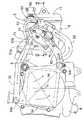
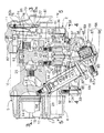
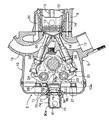
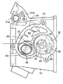
図1〜図5は本発明の一実施例を示すものであり、図1はエンジンの側面図、図2は図1の2−2線拡大断面図、図3は図2の3−3線断面図、図4は図2の4−4線断面図、図5は図2の5−5線断面図である。
【0011】
図1〜図3において、たとえばスクータ型の自動二輪車に搭載されるエンジンEは、たとえば単気筒の4サイクルエンジンであり、そのエンジン本体5は、クランクケース半部7を一体に備えるシリンダブロック6と、前記クランクケース半部7とともにクランクケース9を構成するようにしてクランクケース半部7に結合されるクランクケース半体8と、クランクケース9とは反対側でシリンダブロック6に結合されるシリンダヘッド10と、シリンダブロック6とは反対側でシリンダヘッド10に結合されるヘッドカバー11とを備える。
【0012】
シリンダブロック6内にはシリンダライナ12が設けられており、このシリンダライナ12にはシリンダヘッド10との間に燃焼室13を形成するピストン14が摺動自在に嵌合され、該ピストン14はコンロッド15を介してクランクシャフト16(図1参照)に連結される。
【0013】
シリンダヘッド10の下部側面には排気ポート17が設けられ、この排気ポート17には図示しない排気系が接続される。またシリンダヘッド10の上部側面には吸気ポート18が設けられ、この吸気ポート18には図示しない吸気系が接続される。またシリンダヘッド10には、燃焼室13および排気ポート17間を連通・遮断する排気弁19と、燃焼室13および吸気ポート18間を連通・遮断する吸気弁20とが、開閉作動可能に配設されており、それらの排気弁19及び吸気弁20は動弁機構21により開閉駆動される。
【0014】
該動弁機構21は、前記クランクシャフト16と平行な軸線を有してシリンダヘッド10に回転自在に支承されるカムシャフト22と、該カムシャフト22と平行な軸線を有してシリンダヘッド10に支持される排気側および吸気側ロッカシャフト23,24と、一端を排気弁19に連接せしめるとともに前記カムシャフト22に設けられる排気側カム25に他端を摺接させて排気側ロッカシャフト23で揺動可能に支持される排気側ロッカアーム27と、一端を吸気弁20に連接せしめるとともに前記カムシャフト22に設けられる吸気側カム26に他端を摺接させて吸気側ロッカシャフト24で揺動可能に支持される吸気側ロッカアーム28とを備える。
【0015】
エンジン本体5において、クランクケース9からシリンダブロック6を経てシリンダヘッド10に至るまでの間には、クランクケース9内からのブローバイガスを導くブローバイガス通路として機能するカムチェーン室29が、前記カムシャフト22の一端を臨ませるようにして設けられており、カムシャフト22の一端にはカムシャフト22とは反対側を開放した椀状の被動スプロケット30が固定される。前記カムチェーン室29内には、前記クランクシャフト16からの回転動力を伝達する無端のカムチェーン31が走行可能に収納され、被動スプロケット30に巻掛けられる。これにより、被動スプロケット30およびカムシャフト22には、クランクシャフト16の回転動力が1/2に減速されて伝達される。
【0016】
而してシリンダヘッド10の反クランクシャフト16側の端部には、前記動弁機構21とカムチェーン室29の一端部とを露出させる開口部10aが形成されており、その開口部10aを、シリンダヘッド10に結合した前記ヘッドカバー11が塞いでいる。
【0017】
図4を併せて参照して、シリンダヘッド10の一側面には、前記被動スプロケット30およびカムシャフト22を挿入するための挿入孔32と、該挿入孔32に隣接した位置に配置されるパイプ挿入孔33とが設けられるとともに、それらの孔32,33相互間を仕切るとともに両孔32,33を囲む取付け座34が形成される。而して取付け座34にはカバー35が締結され、前記挿入孔32はカバー35で閉じられる。
【0018】
ところでシリンダヘッド10には、クランクシャフト16に連動して回転する回転部材としてのロータ37と、該ロータ37を収納するケーシング38とを備える補機としてのウォータポンプ36が、前記ケーシング38の一部を前記カバー35で構成するようにして取付けられる。
【0019】
前記ケーシング38は、カムシャフト22側を閉じた有底円筒状に形成されて前記被動スプロケット30内に挿入されるケーシング主体39と、該ケーシング主体39の開放端に嵌合、固定される仕切り板40と、前記カバー35とで構成されるものであり、ケーシング主体39の開放端部は、外方に臨んで前記挿入孔32に設けられる係止段部41に係合するようにして挿入孔32に嵌合され、カバー35は、前記仕切り板40をケーシング主体39との間に挟んでシリンダヘッド10の取付け座34に締結される。
【0020】
ケーシング主体39の閉塞端壁中央部および仕切り板40の中央部には、カムシャフト22と同軸である回転軸42の両端が回転可能に支持される。該回転軸42に固定されるロータ37がケーシング主体39内に収容され、ロータ37の外面には、複数のマグネット43,43…が固着される。一方、ケーシング主体39を覆う被動スプロケット30の内面にも複数のマグネット44,44…が固着されており、クランクシャフト16に連動して被動スプロケット30が回転するのに応じてロータ37が回転軸42とともに回転する。
【0021】
ケーシング主体39内には前記仕切り板40でカバー35側と仕切られた渦室45が形成されており、この渦室45内に収納されるインペラ46がロータ37に設けられる。
【0022】
仕切り板40の中央部で前記回転軸42を囲む複数箇所には、仕切り板40およびカバー35間に形成される吸入室48を渦室45の中央部に連通させる吸入口47…が設けられ、また仕切り板40の外周部には、仕切り板40およびカバー35間に形成される吐出室50を渦室45の外周部に連通させる吐出口49が設けられる。而して吸入室48から吸入口47…を介して渦室45の中央部に吸入された冷却水は、インペラ46の回転によって加圧され、吐出口49から吐出室50に吐出される。しかも吐出室50は、エンジン本体5におけるシリンダブロック6およびシリンダヘッド10に設けられているウォータージャケット51に、導管52(図2では鎖線で示す)を介して接続されており、ウォータポンプ36から吐出される冷却水はウォータージャケット51に戻されることになる。
【0023】
図1に注目して、エンジン本体5のクランクケース9に対応する部分にはラジエータ54が取付けられており、このラジエータ54の入口54aには、前記ウォータージャケット51の第1出口51aが導管55を介して接続される。
【0024】
前記第1出口51aはシリンダヘッド10の上部に設けられるものであり、この第1出口51aに隣接した位置でシリンダヘッド10には、ウォータージャケット51の第2出口51bが設けられ、第2出口51bは第1出口51aよりも小径に形成される。
【0025】
カバー35には、ラジエータ54の出口54bをウォータポンプ36の吸入室48に通じさせる状態と、ウォータージャケット51の第2出口51bをウォータポンプ36の吸入室48に通じさせる状態とを、冷却水の温度に応じて切換える従来周知のサーモスタット55が設けられる。
【0026】
このサーモスタット55が備えるサーモスタットハウジング56は、カバー35に一体に設けられる筒状のハウジング部57と、該ハウジング部57の開口端を塞ぐキャップ58とで構成される。このサーモスタットハウジング56内には、ウォータポンプ36の吸入室48に常時通じる出口室59と、導管62を介してラジエータ54の出口54bに通じる第1入口室60と、導管63を介してウォータージャケット51の第2出口51bに通じる第2入口室61とが形成されており、サーモスタット55は、冷却水の温度が低いときには第1入口室60および出口室59間を遮断するとともに第2出口室61および出口室59間を連通するように作動し、冷却水の温度が高くなったときには第2入口室61および出口室59間を遮断するとともに第1出口室60および出口室59間を連通するように作動する。
【0027】
図5を併せて参照して、シリンダヘッド10には燃焼室13に臨む点火プラグ64が取付けられ、該点火プラグ64を挿入するためのプラグパイプ65の内端がシリンダヘッド10に気密に嵌入される。シリンダヘッド10に設けられているパイプ挿入孔33を貫通したプラグパイプ65の外端は、カバー35に設けられた取付け孔66に嵌合、支持される。而して点火プラグ65に連なるコード67が備えるキャップ67aがプラグパイプ65の外端に気密に嵌合される。
【0028】
ところでカムチェーン室29内のカムチェーン31のうち、前記クランクシャフト16に設けられた駆動スプロケットから被動スプロケット30に向けての往行部すなわち上方走行部31aには、チェーンテンショナ87が弾発的に摺接され、前記カムチェーン31のうち、前記被動スプロケット30から前記駆動スプロケットに向けての復行部すなわち下方走行部31bには、チェーンガイド88が摺接される。
【0029】
チェーンテンショナ87は、カムチェーン31の上方走行部31aに沿って長く形成されるものであり、その一端はクランクシャフト16と平行な軸線まわりの回動を可能としてシリンダブロック6に支承される。またシリンダブロック6にはチエーンテンショナ87をカムチェーン31の上方走行部31aに押し付ける力を発揮するテンショナリフタ89が、前記チェーンテンショナ87の長手方向中間部に当接するようにして取付けられる。
【0030】
このようなカムチェーン31では、その下方走行部31bがほぼ直線状に配置されるのに対し、上方走行部31aは下方に彎曲した配置となっており、被動スプロケット30の近傍において、シリンダライナ12の軸線に平行にして被動スプロケット30の軸線を通る直線90と下方走行部31bとの間のスペースは、前記直線90と上方走行部31aとの間のスペースよりも大きい。
【0031】
プラグパイプ65は、前記カムチェーン31の上方走行部31aおよび下方走行部31b間に配置されるようにしてパイプ挿入孔33を貫通するのであるが、被動スプロケット30の近傍では、上述のように前記直線90よりも下方に大きなスペースが確保されている。このためプラグパイプ65は、外端側に向かうにつれて下方位置となるように傾斜して配置されており、そのような傾斜配置により、プラグパイプ65を前記直線90に沿う方向で被動スプロケット30の軸線により近接させることが可能となり、シリンダ軸線に沿う方向でのエンジン本体5の小型化を図ることができる。しかも外端側に向かうにつれて下方位置となるようにプラグパイプ65が傾斜していることにより、プラグパイプ65からの水抜きも容易となる。
【0032】
前記プラグパイプ65は、シリンダヘッド10のパイプ挿入孔33の側面との間にカムチェーン室29に通じる連通路69を形成してパイプ挿入孔33を貫通するものであり、シリンダヘッド10の取付け座34で囲まれる部分において、シリンダヘッド10およびカバー35の結合面間には、前記連通路69を下部に通じさせるラビリンス通路68が形成される。このラビリンス通路68は、前記カムチェーン室29の外側において、シリンダヘッド10およびカバー35の結合面の少なくとも一方(この実施例では両方)に凹部70を設けるとともに該凹部70の側面から複数の突部71,71…を突出させるようにして構成されるものであり、ラビリンス通路68の下部は、カムチェーン室29のうちブローバイガス通路として機能する部分の下流端に連通路69を介して通じることになる。またこのラビリンス通路68は、図2,4にも示されるように、前記ウォータポンプ36のケーシング38の周囲でシリンダブロック6側に片寄った位置に配置される。
【0033】
またカバー35には、前記ラビリンス通路68の上部に通じる排出管72が取付けられており、この排出管72は、エンジンEにおける吸気系のエアクリーナ(図示せず)に接続される。
【0034】
図2および図3に特に注目して、ヘッドカバー11には、弁カバー74が締結されており、弁カバー74およびヘッドカバー11間にリード弁75が収容される。
【0035】
このリード弁75は、弁カバー74との間に上流側弁室80aを形成するとともにヘッドカバー11との間に下流側弁室80bを形成してヘッドカバー11および弁カバー74間に挟持される支持板79と、下流側弁室80b内で支持板79に取付けられるストッパ85と、支持板79およびストッパ85間に挟まれる弁シート77およびリード弁板78とを備えるものであり、支持板79および弁シート77には、リード弁板78で塞ぎ得る弁孔76が設けられる。
【0036】
弁カバー74には、エンジンEの吸気系におけるエアクリーナから計量された2次空気を上流側弁室79に導入するための空気導入口81が設けられる。また下流側弁室80bは、排気ポート17に開口するようにしてシリンダヘッド10に設けられている2次空気通路83に、シリンダヘッド10およびヘッドカバー11間に跨がる円筒状のノックピン82を介して連通される。
【0037】
したがって排気ポート17で生じる排気脈動に応じて、リード弁75が開閉して2次空気が排気ガスに混入され、排気ガス中のHCおよびCO等の未燃有害成分を酸化、浄化することになる。
【0038】
また下流側弁室80b内でヘッドカバー11には、排気ポート17側から逆流してくる高温の排気ガスにリード弁75が曝されることを回避するための多孔板状の遮熱板84が固定される。
【0039】
次にこの実施例の作用について説明すると、ブローバイガスを導くブローバイガス通路としてのカムチェーン室29がエンジン本体5に設けられており、このカムチェーン室29においてブローバイガス通路として機能する部分の下流端に通じるラビリンス通路68が、エンジン本体50のシリンダヘッド10、ならびに該シリンダヘッド10に結合されるカバー35の結合面間に形成されている。しかもカバー35は、シリンダヘッド10に取付けられるウォータポンプ36が備えるケーシング38の一部を構成するものである。
【0040】
したがってブローバイガス中からオイル成分を効果的に分離するラビリンス通路68を、ウォータポンプ36以外の他の部品を用いることなく簡単に形成することができ、ブリーザプレートをエンジン本体に取付けるようにしていた従来のブリーザ構造に比べると、部品点数の低減を図るとともに作業工数を低減することができる。
【0041】
またウォータポンプ36が備えるケーシング38の一部を構成するカバー35で、ラビリンス通路68の一部が形成されるので、ウォータポンプ36内の冷却水によってラビリンス通路68の温度が良好に保持される。すなわちブローバイガス中の水蒸気が結露せず、かつブローバイガス中のオイルがガス化しない程度にり、ラビリンス通路68の温度が保持され、ラビリンス通路68でオイル成分をより効果的に分離してオイル消費量を減少することができる。
【0042】
以上、本発明の実施例を説明したが、本発明は上記実施例に限定されるものではなく、特許請求の範囲に記載された本発明を逸脱することなく種々の設計変更を行うことが可能である。
【0043】
【発明の効果】
以上のように本発明によれば、シリンダヘッドに取付けられるウォータポンプのケーシングの一部であるポンプカバーと、シリンダヘッドとの結合面間に、カムチェーン室においてブローバイガス通路として機能する部分の下流端に通じるラビリンス通路が形成されるので、ブローバイガス中からオイル成分を効果的に分離するラビリンス通路を、ウォータポンプ以外の他の部品を用いることなく簡単に形成することができ、部品点数の低減を図るとともに作業工数を低減することができる。
【0044】
またウォータポンプ内の冷却水によって、ブローバイガス中の水蒸気が結露せず、かつブローバイガス中のオイルがガス化しない程度にラビリンス通路の温度を保持することができ、オイル成分をより効果的に分離してオイル消費量を減少することができる。
【図面の簡単な説明】
【図1】 エンジンの側面図である。
【図2】 図1の2−2線拡大断面図である。
【図3】 図2の3−3線断面図である。
【図4】 図2の4−4線断面図である。
【図5】 図2の5−5線断面図である。
【符号の説明】
5・・・・エンジン本体
9・・・・クランクケース
10・・・シリンダヘッド
10a・・開口部
11・・・ヘッドカバー
16・・・クランクシャフト
21・・・動弁機構
29・・・カムチェーン室
31・・・カムチェーン
35・・・ポンプカバーとしてのカバー
36・・・ウォータポンプ
37・・・回転部材としてのロータ
38・・・ケーシング
64・・・点火プラグ
65・・・プラグパイプ
68・・・ラビリンス通路
E・・・・エンジン[0001]
BACKGROUND OF THE INVENTION
The present invention relates to a breather structure for an engine, and in particular, an auxiliary machine including a rotating member that rotates in conjunction with a crankshaft and a casing that houses the rotating member has a cover coupled to the engine body as a part of the casing. The present invention relates to an improvement in a breather structure for improving the gas-liquid separation performance of blow-by gas in an engine attached to an engine body.
[0002]
[Prior art]
Conventionally, breather structures in which an oil component is separated from blow-by gas and only the gas component is guided to an air cleaner or the like are known, for example, in Japanese Utility Model Publication Nos. 55-45044 and 57-6728.
[0003]
[Problems to be solved by the invention]
In the above conventional one, the oil component is separated from the blow-by gas by circulating the blow-by gas through a bent flow path formed between the head cover and the breather plate attached to the inner surface of the head cover. . Accordingly, in the structure, a breather plate is required, and an operation for attaching the breather plate to the head cover is also required.
[0004]
The present invention has been made in view of such circumstances, and a breather in an engine that can effectively separate an oil component from blow-by gas while reducing the number of parts and reducing the number of work steps. The purpose is to provide a structure.
[0005]
[Means for Solving the Problems]
In order to achieve the above object, according to the first aspect of the present invention, the cylinder head of the engine body is provided with a valve operating mechanism that is interlocked with the crankshaft via the cam chain. The engine body houses the cam chain. In a breather structure in an engine in which a cam chain chamber is formed so as to function as a blow-by gas passage that guides blow-by gas from inside the crankcase, the valve mechanism and the end of the cylinder head on the side opposite to the crankshaft are An opening that exposes one end of the cam chain chamber is formed, a head cover that closes the opening is coupled to the cylinder head, and rotates in conjunction with the crankshaft. water pump and a casing for housing is coupled to one side of the cylinder head The pump cover as part of the casing, attached to the cylinder head, labyrinth passageway leading to the downstream end of the portion functioning as the blow-by gas passage in the cam chain chamber, the cylinder head and outside of the cam chain chamber It is formed between the coupling surfaces of the pump cover , and is arranged at a position offset to the cylinder block side around the casing .
[0006]
According to such a configuration, a pump cover, which is part of the casing of the water pump mounted on the cylinder head, between coupling surfaces of the cylinder head, the downstream end of the portion functioning as a blow-by gas passage in the cam chain chamber Since a labyrinth passage is formed, it is possible to easily form a labyrinth passage that effectively separates oil components from the blow-by gas without using other parts than the water pump , thereby reducing the number of parts. At the same time, the number of work steps can be reduced.
[0007]
Also by the cooling water in the U Otaponpu, without condensation of water vapor in the blow-by gas, and oil in the blow-by gas is in the temperature of the labyrinth passage to the extent not gasified is maintained, the oil component more effectively Separation can reduce oil consumption.
[0008]
According to a second aspect of the present invention, in addition to the configuration of the first aspect of the present invention, a plug pipe for mounting a spark plug to the cylinder head crosses the labyrinth passage and the cam chain chamber. It is attached to the head.
[0009]
DETAILED DESCRIPTION OF THE INVENTION
Embodiments of the present invention will be described below based on one embodiment of the present invention shown in the accompanying drawings.
[0010]
1 to 5 show an embodiment of the present invention, FIG. 1 is a side view of an engine, FIG. 2 is an enlarged sectional view taken along line 2-2 of FIG. 1, and FIG. 3 is line 3-3 of FIG. 4 is a sectional view taken along line 4-4 of FIG. 2, and FIG. 5 is a sectional view taken along line 5-5 of FIG.
[0011]
1 to 3, for example, an engine E mounted on a scooter type motorcycle is, for example, a single-cylinder four-cycle engine, and an
[0012]
A
[0013]
An
[0014]
The
[0015]
In the
[0016]
Thus, an opening 10a that exposes the
[0017]
Referring also to FIG. 4, an
[0018]
By the way, the
[0019]
The
[0020]
Both ends of a
[0021]
A
[0022]
At a plurality of locations surrounding the
[0023]
Referring to FIG. 1, a
[0024]
The
[0025]
The
[0026]
The
[0027]
Referring also to FIG. 5, a
[0028]
By the way, in the
[0029]
The
[0030]
In such a
[0031]
The
[0032]
The
[0033]
The
[0034]
With particular attention to FIGS. 2 and 3, a
[0035]
This
[0036]
The
[0037]
Accordingly, the
[0038]
In the
[0039]
Next, the operation of this embodiment will be described. A
[0040]
Therefore, the
[0041]
Moreover, since the
[0042]
Although the embodiments of the present invention have been described above, the present invention is not limited to the above-described embodiments, and various design changes can be made without departing from the present invention described in the claims. It is.
[0043]
【The invention's effect】
As described above, according to the present invention, between the coupling surface between the pump cover, which is a part of the casing of the water pump attached to the cylinder head, and the cylinder head, downstream of the portion functioning as the blow-by gas passage in the cam chain chamber. Since the labyrinth passage leading to the end is formed, the labyrinth passage that effectively separates the oil component from the blow-by gas can be easily formed without using other parts other than the water pump , and the number of parts can be reduced. As a result, the number of work steps can be reduced.
[0044]
The cooling water in the water pump keeps the temperature of the labyrinth passage so that the water vapor in the blow-by gas is not condensed and the oil in the blow-by gas is not gasified, so that the oil components are separated more effectively. Thus, oil consumption can be reduced.
[Brief description of the drawings]
FIG. 1 is a side view of an engine.
FIG. 2 is an enlarged cross-sectional view taken along line 2-2 of FIG.
3 is a cross-sectional view taken along line 3-3 of FIG.
4 is a cross-sectional view taken along line 4-4 of FIG.
5 is a cross-sectional view taken along line 5-5 of FIG.
[Explanation of symbols]
5 ... Engine body
9 ...
10a ... Opening
11 ... Head cover 16 ... Crankshaft
21 ...
31 ...
64 ... Spark plug
65 ...
Claims (2)
前記シリンダヘッド(10)の反クランクシャフト(16)側の端部には、前記動弁機構(21)と前記カムチェーン室(29)の一端部とを露出させる開口部(10a)が形成されると共に、その開口部(10a)を塞ぐヘッドカバー(11)が該シリンダヘッド(10)に結合され、
前記クランクシャフト(16)に連動して回転する回転部材(37)と、該回転部材(37)を収納するケーシング(38)とを備えるウォータポンプ(36)が、前記シリンダヘッド(10)の一側面に結合されるポンプカバー(35)を前記ケーシング(38)の一部として、該シリンダヘッド(10)に取付けられ、
前記カムチェーン室(29)において前記ブローバイガス通路として機能する部分の下流端に通じるラビリンス通路(68)が、該カムチェーン室(29)の外側で前記シリンダヘッド(10)および前記ポンプカバー(35)の結合面間に形成され、且つ前記ケーシング(38)の周囲でシリンダブロック(6)側に片寄った位置に配置されることを特徴とする、エンジンにおけるブリーザ構造。 The cylinder head (10) of the engine body (5) is provided with a valve mechanism (21) that is linked to the crankshaft (16) via a cam chain (31). The engine body (5) has a cam chain ( In a breather structure in an engine in which a cam chain chamber (29) containing 31) is formed so as to function as a blow-by gas passage for guiding blow-by gas from within the crankcase (9),
An opening (10a) that exposes the valve mechanism (21) and one end of the cam chain chamber (29) is formed at the end of the cylinder head (10) on the side opposite to the crankshaft (16). And a head cover (11) that closes the opening (10a) is coupled to the cylinder head (10),
A water pump (36) including a rotating member (37) that rotates in conjunction with the crankshaft (16) and a casing (38) that houses the rotating member (37) is provided as one of the cylinder heads (10). A pump cover (35) coupled to a side surface is attached to the cylinder head (10) as a part of the casing (38) ,
In the cam chain chamber (29), a labyrinth passage (68) communicating with the downstream end of the portion functioning as the blow-by gas passage is formed outside the cam chain chamber (29), and the cylinder head (10) and the pump cover (35). The breather structure in the engine is characterized in that the breather structure is disposed between the coupling surfaces of the cylinder block (6) and is offset from the cylinder block (6) side around the casing (38) .
Priority Applications (5)
| Application Number | Priority Date | Filing Date | Title |
|---|---|---|---|
| JP2000187526A JP4441069B2 (en) | 2000-06-19 | 2000-06-19 | Breather structure in engine |
| IT2001TO000578A ITTO20010578A1 (en) | 2000-06-19 | 2001-06-15 | BREATHER STRUCTURE IN AN ENGINE. |
| ES200101402A ES2183719B1 (en) | 2000-06-19 | 2001-06-15 | MOTOR BREATHER STRUCTURE. |
| TW090210202U TW496467U (en) | 2000-06-19 | 2001-06-18 | Breather structure in engine |
| CNB011216247A CN1177996C (en) | 2000-06-19 | 2001-06-19 | Ventilation structure of engine |
Applications Claiming Priority (1)
| Application Number | Priority Date | Filing Date | Title |
|---|---|---|---|
| JP2000187526A JP4441069B2 (en) | 2000-06-19 | 2000-06-19 | Breather structure in engine |
Publications (2)
| Publication Number | Publication Date |
|---|---|
| JP2002004828A JP2002004828A (en) | 2002-01-09 |
| JP4441069B2 true JP4441069B2 (en) | 2010-03-31 |
Family
ID=18687493
Family Applications (1)
| Application Number | Title | Priority Date | Filing Date |
|---|---|---|---|
| JP2000187526A Expired - Fee Related JP4441069B2 (en) | 2000-06-19 | 2000-06-19 | Breather structure in engine |
Country Status (5)
| Country | Link |
|---|---|
| JP (1) | JP4441069B2 (en) |
| CN (1) | CN1177996C (en) |
| ES (1) | ES2183719B1 (en) |
| IT (1) | ITTO20010578A1 (en) |
| TW (1) | TW496467U (en) |
Families Citing this family (4)
| Publication number | Priority date | Publication date | Assignee | Title |
|---|---|---|---|---|
| ES2402686T3 (en) * | 2003-07-10 | 2013-05-07 | Yamaha Hatsudoki Kabushiki Kaisha | Engine |
| US7503317B2 (en) * | 2005-09-15 | 2009-03-17 | Kohler Co. | Internal breather for an internal combustion engine |
| JP2008019794A (en) * | 2006-07-13 | 2008-01-31 | Toyota Motor Corp | Blow-by gas recovery structure of internal combustion engine, chain cover unit used in same blow-by gas recovery structure |
| US10151225B2 (en) * | 2016-10-26 | 2018-12-11 | GM Global Technology Operations LLC | Integrated oil separator assembly for crankcase ventilation |
Family Cites Families (3)
| Publication number | Priority date | Publication date | Assignee | Title |
|---|---|---|---|---|
| DE4000060C1 (en) * | 1990-01-03 | 1991-02-21 | Dr.Ing.H.C. F. Porsche Ag, 7000 Stuttgart, De | |
| DE4415407A1 (en) * | 1994-05-02 | 1995-11-09 | Hengst Walter Gmbh & Co Kg | Crankcase ventilation for an internal combustion engine |
| GB9526349D0 (en) * | 1995-12-22 | 1996-02-21 | Rover Group | Separation of oil fromair breather gases |
-
2000
- 2000-06-19 JP JP2000187526A patent/JP4441069B2/en not_active Expired - Fee Related
-
2001
- 2001-06-15 ES ES200101402A patent/ES2183719B1/en not_active Expired - Fee Related
- 2001-06-15 IT IT2001TO000578A patent/ITTO20010578A1/en unknown
- 2001-06-18 TW TW090210202U patent/TW496467U/en not_active IP Right Cessation
- 2001-06-19 CN CNB011216247A patent/CN1177996C/en not_active Expired - Fee Related
Also Published As
| Publication number | Publication date |
|---|---|
| ES2183719B1 (en) | 2004-04-01 |
| JP2002004828A (en) | 2002-01-09 |
| ES2183719A1 (en) | 2003-03-16 |
| ITTO20010578A1 (en) | 2002-12-15 |
| CN1330211A (en) | 2002-01-09 |
| TW496467U (en) | 2002-07-21 |
| CN1177996C (en) | 2004-12-01 |
Similar Documents
| Publication | Publication Date | Title |
|---|---|---|
| KR100576964B1 (en) | Variable stroke engine | |
| JP4119023B2 (en) | Breather device in engine | |
| JP2012077756A (en) | Two-stroke internal combustion engine | |
| JP4698623B2 (en) | Breather device for internal combustion engine | |
| US6021766A (en) | Breather device for engine | |
| JP3881796B2 (en) | Engine cooling system | |
| JP3975150B2 (en) | Breather structure of overhead valve internal combustion engine | |
| JP2011196319A (en) | Engine breather device | |
| JP3875417B2 (en) | Fuel injection device for vehicle engine | |
| KR100688221B1 (en) | Subsidiary mechanism attachment structure of internal combustion engine | |
| JP4441069B2 (en) | Breather structure in engine | |
| JP3971842B2 (en) | Outboard motor | |
| JP3963292B2 (en) | Outboard engine | |
| JP4067068B2 (en) | 4-cycle engine | |
| KR20090088301A (en) | Cooling structure for belt-type continuously variable transmission | |
| JP2004316633A (en) | Cylinder head of internal combustion engine | |
| JP4007885B2 (en) | Air pump drive | |
| JPH10121930A (en) | Installing device for oil pump in engine | |
| JP4458626B2 (en) | Exhaust gas purification device for engine | |
| JP4057725B2 (en) | Horizontally opposed 4-cycle engine for motorcycles | |
| JP3619342B2 (en) | Internal combustion engine | |
| JP4010901B2 (en) | Engine fuel injector | |
| JP3966784B2 (en) | Engine fuel injector | |
| JP3139089B2 (en) | 4 cycle engine | |
| JP3875603B2 (en) | Air fuel injection engine |
Legal Events
| Date | Code | Title | Description |
|---|---|---|---|
| A621 | Written request for application examination |
Free format text: JAPANESE INTERMEDIATE CODE: A621 Effective date: 20070326 |
|
| A977 | Report on retrieval |
Free format text: JAPANESE INTERMEDIATE CODE: A971007 Effective date: 20090604 |
|
| A131 | Notification of reasons for refusal |
Free format text: JAPANESE INTERMEDIATE CODE: A131 Effective date: 20090715 |
|
| A521 | Written amendment |
Free format text: JAPANESE INTERMEDIATE CODE: A523 Effective date: 20090914 |
|
| TRDD | Decision of grant or rejection written | ||
| A01 | Written decision to grant a patent or to grant a registration (utility model) |
Free format text: JAPANESE INTERMEDIATE CODE: A01 Effective date: 20091222 |
|
| A01 | Written decision to grant a patent or to grant a registration (utility model) |
Free format text: JAPANESE INTERMEDIATE CODE: A01 |
|
| A61 | First payment of annual fees (during grant procedure) |
Free format text: JAPANESE INTERMEDIATE CODE: A61 Effective date: 20100108 |
|
| FPAY | Renewal fee payment (event date is renewal date of database) |
Free format text: PAYMENT UNTIL: 20130115 Year of fee payment: 3 |
|
| R150 | Certificate of patent or registration of utility model |
Free format text: JAPANESE INTERMEDIATE CODE: R150 |
|
| FPAY | Renewal fee payment (event date is renewal date of database) |
Free format text: PAYMENT UNTIL: 20130115 Year of fee payment: 3 |
|
| FPAY | Renewal fee payment (event date is renewal date of database) |
Free format text: PAYMENT UNTIL: 20140115 Year of fee payment: 4 |
|
| LAPS | Cancellation because of no payment of annual fees |