JP4440423B2 - Windmill device and ball game machine - Google Patents
Windmill device and ball game machine Download PDFInfo
- Publication number
- JP4440423B2 JP4440423B2 JP2000121193A JP2000121193A JP4440423B2 JP 4440423 B2 JP4440423 B2 JP 4440423B2 JP 2000121193 A JP2000121193 A JP 2000121193A JP 2000121193 A JP2000121193 A JP 2000121193A JP 4440423 B2 JP4440423 B2 JP 4440423B2
- Authority
- JP
- Japan
- Prior art keywords
- rotating body
- decorative
- mounting
- board
- disc
- Prior art date
- Legal status (The legal status is an assumption and is not a legal conclusion. Google has not performed a legal analysis and makes no representation as to the accuracy of the status listed.)
- Expired - Fee Related
Links
Images


Landscapes
- Pinball Game Machines (AREA)
Description
【0001】
【発明の属する技術分野】
本発明はパチンコ遊技機、じゃん球遊技機などの弾球遊技機の遊技盤の遊技領域内に取り付けられる風車装置および弾球遊技機に関する。
【0002】
【従来の技術】
風車装置は、パチンコ遊技機の遊技盤の遊技領域内に取り付けられ、遊技球の落下進路を変えるもので、落下する遊技球が回転体に接触し、はじき飛ばされることによりその進路を変えるものであり、従来から種々の機構、構造のものが使用されている。近時は、電飾効果を兼ね備えたランプなどの光源内蔵のものも提案されている。
【0003】
これらのものは、例えば、実開平6-17783号公報、特開平8-229199号公報あるいは特開平11-235424号公報などに記載されるように、それぞれ部品名称の表現は異なるものの、落下する遊技球が接触することにより回転する回転体と、回転体を回転自在に支承し、遊技盤に取り付ける取り付け基板と、取り付け基板に内蔵され光源を取り付けたランプ基板と、からなるものであり、その細部構造は異なるもののランプ基板に取り付けた光源の照明で回転体すなわち風車を照明しつつ遊技球の落下進路を変えている。
【0004】
これら従来の風車装置にあっては、いずれも、風車装置を組み立てる部品点数が多く、組立も煩瑣でコストが高いという問題があり、また、装飾性あるいは遊技者への訴求性が必ずしも高いというものではない。
【0005】
【発明が解決しようとする課題】
本発明は、かかる従来技術の問題に鑑みなされたものであり、コストが低く、電飾性に優れ、訴求性の高い風車装置およびこのような風車装置を設けた弾球遊技機を提供するものである。
【0006】
【課題を解決するための手段】
すなわち、本発明の風車装置は、落下する遊技球が接触することにより回転する回転体と、該回転体を回転自在に支承し、遊技盤に取り付ける取り付け基板と、取り付け基板に内蔵され光源を取り付けたランプ基板とからなる弾球遊技機の風車装置において、前記回転体が、飾り円板と、該飾り円板を取り付ける円板取り付け部と該円板取り付け部に連なり周面に回転翼を突き出した胴部を有する回転本体と、からなり、前記取り付け基板には、前記回転体を回転自在に支承する金属製の支承軸が一体成形されるとともに、取り付け縁部が周縁に形成され、かつ前記支承軸のボス部、ねじボス部および該両ボス部を取り囲み光源室を形成するよう前記ねじボス部の突出方向に延在するスカート部が裏面に形成され、前記ボス部後端には、段差を有する位置決めピンが形成され、前記ランプ基板は、前記位置決めピンが嵌着する位置決め孔を有し、前記光源室が被覆されるように前記取り付け基板に取り付けられ、前記位置決めピンの前記段差が、前記スカート部の延在方向の高さより高い位置に設けられていることを特徴とする。
この構成により、回転体が、飾り円板と翼を取り付けた回転本体とからなるので、回転性能を向上した上で、製造が容易で、部品点数が少なく、また、装飾性にも優れたコストの低い風車装置を提供できる。
【0007】
また、本発明の風車装置は、取り付け基板に回転体の金属製の支承軸を一体成形したので、装置の剛性を増し、部品点数も減り、組立性が向上する。
さらに、飾り円板および回転本体が、それぞれ中央部に形成された軸受け孔を介して支承軸に回転自在に支承され、飾り円板の後面に係止爪と位置決め突起を形成し、回転本体の円板取り付け部には飾り円板が嵌着する凹部、係止爪を挿入する係止孔および位置決め突起を嵌入する位置決め孔を形成するとともに、係止爪および係止孔が、それぞれ飾り円板および回転本体の径方向内方であって軸受け孔を囲む位置に設けられ、飾り円板が、位置決め突起を位置決め孔に嵌入することにより回転本体に対して位置決めされるとともに、係止爪を係止孔に挿入することにより回転本体に組み込まれるようにしたものは、成形性がよく、組立性を向上するとともに組立回転体の一体性が増し、装飾、電飾効果も向上する。本発明風車装置のその他の特徴、作用効果については実施形態の説明において詳述する。
【0008】
本発明の弾球遊技機は、取り付け基板に複数の回転体を取り付けた本発明にかかる風車装置を設けたものであり、コストおよび組立工数を大幅に増加することなく、複数あるいは連風車を設け、遊技機の電飾性能の向上、訴求性の向上に寄与できる。また、取り付け基板を左右対称の円弧状に形成し、この風車装置を遊技盤の遊技領域の周縁に、左右対称に取り付けることにより、電飾性に優れ、均整な弾球遊技機を提供できる。
【0009】
【発明の実施の形態】
以下、図示した本発明の実施形態に基づき本発明を詳細に説明する。
【0010】
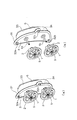
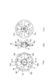
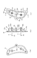
図1は、本発明風車装置の一実施形態の斜視図であり、図1(a)は組立斜視図、図1(b)は部分分解斜視図である。図2から図6は、図1の実施形態の各部品を示す拡大図である。図2は、飾り円板を示す図であり、図2(a)は正面図、図2(b)は図2(a)のA-A断面図、図2(c)は背面図である。図3は、回転本体を示す図であり、図3(a)は正面図、図3(b)は図3(a)のB-B断面図、図3(c)は背面図である。図4は、取り付け基板を示す図であり、図4(a)は正面図、図4(b)は図4(c)のC-C断面図、図4(c)は背面図である。図5は、止め輪を示す図であり、図5(a)は側断面図、図5(b)は正面図である。図6は、ランプ基板を示す図であり、図6(a)は正面図、図6(b)は側面図、図6(c)は背面図である。
【0011】
図1において、飾り円板1を回転本体2に組み込んだ2組の回転体すなわち風車が、取り付け基板3に一体成形された2個の金属製の支承軸4に挿着(図1(b))され、止め輪5により支承軸4に回転自在に保持される。取り付け基板3の周縁には取り付け縁部31が形成され、3個のねじ孔32a、32b、32cからねじ(図示せず)により遊技盤面に取り付けられる。取り付け基板3の裏面には光源室3Aを形成するスカート部33が設けられる。ランプ基板6は光源室3Aを被覆するように取り付け基板3の裏面にねじ(図示せず)で固定される。
【0012】
飾り円板1は、図2に示すように、やや前方に反った円板で中央のボス部11の中心には、止め輪収納穴12と軸受け孔13が穿たれており、またボス部11の外周縁には等配に3個の係止爪14a、14b、14cが形成され、ボス部11の裏面には係止爪14aと14bの間および14bと14cの間にそれぞれ位置決め突起15aおよび15bが形成される(図2(c))。また、円板周縁前面にはリム16が形成され、その内側は大小各3個、計6個の穴16a、16b、16c、16d、16e、16fが抜かれている。この飾り円板1は着色プラスチックで一体成形される。
【0013】
回転本体2は、図3に示すように、飾り円板1が嵌着する円状の凹部21aを形成した円板取り付け部21とこの円板取り付け部21に連なり裏面に延びた胴部22と胴部22の外周面から放射状に突き出して形成された3個の回転翼23a、23b、23cとからなり、透明プラスチックで一体成形されるものである。円板取り付け部21の中央部には飾り円板1の3個の係止爪14a、14b、14cが係合する係止穴24a、24b、24cが穿たれ、また、飾り円板1の位置決め突起15a、15bが嵌入する位置決め穴25a、25bが形成されている。胴部22は中空に形成され、飾り円板1の軸受け孔13のボス部13aを受ける受け座22aと軸受け孔22bが形成されている。
【0014】
取り付け基板3は、図4に示すように、その周縁には取り付け縁部31が形成され、3個のねじ孔32a、32b、32cからねじ(図示せず)により遊技盤面に取り付けられる。取り付け基板3の裏面には光源室3Aを形成するスカート部33が設けられる。金属製の各支承軸4は2個の軸ボス部34a、34bに支承されるように取り付け基板3と一体成形(インサート成形)されており、その先端部には止め輪5固定用の係止溝4aが形成されている。基板裏面略中央部にはランプ基板6を固定するためのねじボス35が突き出して成形され、スカート部33は、基板補強用のリブとして軸ボス部34a、34bを囲み、ねじボス35に連なり、上下に区画された光源室3Aを形成している。また、軸ボス部34a、34bの先端には段付きの位置決めピン36a、36bが形成されている。なお、33aは、ランプ基板6のコネクタ(後述)を逃げる切り欠きであり、37a、37bは遊技盤に風車装置を取り付ける際の位置決めピンであり、遊技盤の位置決め孔に嵌合するものである。
【0015】
飾り円板1と回転本体2を組み立てた回転体(風車)は、支承軸4に挿着され軸受け孔部で軸に回転自在に保持(ラジアル支持)されるが、軸方向の支持(スラスト支持)は、止め輪5で行われる。止め輪5は、図5に示すように飾り円板1の止め輪収納穴12に嵌着保持される外径を有する中空のリングでその中空部の内周には前記支承軸4の係止溝4aに嵌着する突条5aを有している。止め輪5はプラスチックで成形され、弾性を有するので若干締まり目の嵌合公差により突条5aが前記係止溝4aに填り込み組立回転体を支承軸4に保持する。
【0016】
ランプ基板6は、図6に示すように、前述の光源室3Aを構成するスカート部33の外形に略等しい外形を有する回路基板であって、その表面には、6個の光源すなわち本実施形態においてはLED(発光ダイオード)61a、61b、61c、61d、61e、61fが取り付けられ、二つに区画された光源室に各3個の光源が内蔵されるようにしている。基板には電源回路(図示せず)が形成され、コネクタ62により外部回路基板に接続される。63はねじ止めのための孔であり、ねじにより取り付け基板3のねじボス35に固定される。ランプ基板6の取り付け基板3への取り付けに際しては、位置決め孔64a、64bを取り付け基板3の位置決めピン36a、36bに嵌め込むことにより、左右および前後の位置を決めて取り付けることができる。
【0017】
以上の風車装置を製造し、組み立てる際は、まず、飾り円板1、回転本体2、支承軸4をインサートした取り付け基板3および止め輪5をそれぞれプラスチック材で成形し、またランプ基板を別途組み立てて準備しておく。遊技盤への取り付けに際しては、飾り円板1の止め輪収納孔12に止め輪5を嵌合した後係止爪14a、14b、14cを内側にすぼめ、飾り円板1の位置決め突起15a、15bを回転本体2の位置決め孔25a、25bに合わせ、飾り円板1を回転本体2の前面から装着する。係止爪14a、14b、14cが係止孔24a、24b、24cに嵌入すると爪の鉤が拡がり、係止爪14a、14b、14cは円板取り付け部21の裏面に噛み込み、飾り円板1と止め輪5の組立体は凹部21aに嵌着され、一体となった風車すなわち回転体が構成される。
【0018】
この組立回転体を2個、予め回路基板6を取り付けた取り付け基板3の二つの支承軸4の前から押し込めば支承軸4に各組立回転体が回転自在に保持され、ランプ付きの風車装置は完成する。遊技盤に取り付ける際は取り付け基板3の位置決めピン37a、37bを遊技盤の位置決め孔に合わせてねじ孔32a、32b、32cでねじ止めして取り付ける。なお、場合によっては、LEDを取り付けた回路基板6を組み込んだ取り付け基板3を先に遊技盤に取り付け、後に各組立回転体(風車)を支承軸4に挿着することもできる。
【0019】
以上のように、本発明の風車装置の回転体(風車)は、飾り円板1と回転本体2の単部品から構成され、部品点数の少ない複雑な風車形状を可能としたものであり、飾り円板1は円板形の単純な形状を基本とした成形(射出成形)が可能な形状であり、円板部の抜き孔16も係止爪の14の成形型抜き孔を兼ねて、任意の形状で抜くことができ、形状に変化を持たせることもできる。また、円板単独で独自の着色プラスチックを使用することもでき、この場合は多彩で変化に富んだ風車を構成することができる。
【0020】
また、回転本体2も成形可能な形状であり、胴部22には回転翼23を形成し、遊技球が落下するポケットを形成しているので遊技球のエネルギを回転エネルギに効率よく変換できる。また、これを透明プラスチックで製作した場合は光源の光を前面の飾り円板1に伝える導光体として機能し、装飾効果、電飾効果を上げることができる。
【0021】
また、本発明の風車装置は、飾り円板1を回転本体2に組み込んだ回転体(風車)を金属製の支承軸4を一体成型した取り付け基板3に取り付けるようになしているので部品点数が少なく、成形性、組立性を向上している。また、飾り円板1および回転本体2に軸受け孔13および22bを形成しているので安定した回転を保証でき、また、軸受け耐久性を向上している。更には、組立回転体のスラスト方向は別体の止め輪5で止めているので、止め輪5の材質を最適化することもできる。
【0022】
取り付け基板3においては、リブをかねるスカート部33で光源室3Aを構成しているので、合理的形態であり、また、金属製の支承軸4をインサート成形し、その軸端を位置決めピン36a、36bと兼用しているので、取り付け基板3の剛性、強度を増し、形状を合理的、機能的になしている。実施形態のものにあっては、スカート部33の幅(高さ)より、高い位置に位置決めピン36a、36bの段差を高い位置に形成して回路基板6と光源室3Aの間に隙間を設け、光源LED61a〜61fの放熱を行うようになしている。
【0023】
本発明の風車装置は、飾り円板1と回転本体2および止め輪を5を組み込んだ組立回転体(風車)を取り付け基板3に取り付けるようになしているので、多彩で変化に富んだ風車装置を提供するとともに製造が容易で組み立て性を向上したコストの低い風車装置を実現できる。
【0024】
以上の実施形態の説明においては、1個の取り付け基板に2本の支承軸を設けた2連風車装置を説明した。この場合、複雑でかつコンパクトな実用性の高い風車装置を提供できるが、取り付けスペースの関係では、1個の取り付け基板に1個の風車(回転体)を設けたものでもよく、2連以上3連、4連などの風車を取り付けることもできる。また、金属製の支承軸を取り付け基板に一体成型することは種々の効果を生むが場合によっては支承軸をプラスチックで成形することもでき、金属製の支承軸を接着剤などで取り付け基板に固着することもできる。
【0025】
飾り円板の形状についていえば、抜き孔は係止爪の鉤部の成形のための型抜きに必要な孔が抜いてあればよく、抜き孔の形状、数は適宜装飾効果、電飾効果を高めるように定めることができる。また、回転本体の円板取り付け部の形状についていえば、必ずしも円板状の取り付け部でなくともよく飾り円板を一体的に保持できる形状であればよく、飾り円板の形状との兼ね合いで適宜の形態をとりうる。さらに、回転本体の回転翼の形状は遊技球を受けるポケットが形成できるものであればよく、また、その数も必ずしも3枚である必要はなく、場合によっては1枚あるいは風車の大きさによっては3枚以上も可能である。
【0026】
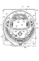
次に本発明の弾球遊技機について説明する。図7は本発明の風車装置の前述の実施形態のものを装備した本発明にかかる新規なパチンコ遊技機一例の遊技盤の正面図である。
【0027】
図7において、遊技盤100の略円形の遊技領域Rは、内レール110(アウト口と一体になったアウト口レール)と遊技領域Rの上部および右側部を画定する枠飾り120により略円形に画定される。内レール110の外側には外レール130が内レールと略並行に設けられ遊技球を誘導する弓状の誘導路を形成している。
【0028】
遊技領域R内には、遊技くぎ(図示せず)が植設され、遊技球の落下路を形成している。頂部のいわゆる天釘(図示せず)の下部には弓状のラウンドレンズ140が設けられ、その下方には図柄表示部150が位置する。図柄表示部150は、頂部に突出た凸ステージ部151と両側のワープルート152、153と底部の凹んだ凹ステージ154を有する略四角のフレーム150Aに特別図柄表示装置155を組み込んだものであり、遊技領域中央やや上方に設けられる。
【0029】
凸ステージ部151前面には、中央飾り156が設けられ、中央飾り156の上半分は金属飾り156aであり、金属飾り156aの下には表示装置156bが設けられる。表示装置156bの中央には普通図柄表示装置、その両脇に各2個の普通図柄始動の保留球表示ランプ、さらにその両側に各2個の特別図柄始動の保留球表示ランプが取付けられている。中央飾り156の両側の盤面にはラウンドレンズ140に平行な補助レンズ157a、157bが取付けられている。
【0030】
ワープルート153の右外側には、上述の実施形態の風車装置162が取り付けられ、ワープルート152の左外側には、風車装置162と機能、構成は同一であるが、形状が左右対称形である風車装置161が取り付けられている。
【0031】
各風車装置161、162の下方側部には二つの一般入賞口171a、171bを取付け、電飾ランプ171cを内蔵したサイドレンズ171と、同じく二つの一般入賞口172a、172bを取付け、電飾ランプ172cを内蔵したサイドレンズ172が左右対称に取付けられている。表示装置150の中央下方には電動役物で、羽根が開閉する電動チューリップ180、その下方でアウト穴190の上には開閉扉を有するアタッカー(大入賞口)200が設けられ、アタッカー(大入賞口)200左上方には始動口210が位置している。
【0032】
このパチンコ遊技機においては、各役物の配置形状は異なるもののその遊技方法は従来の遊技盤と変わるところはないので説明は省略する。本パチンコ遊技機にあっては、本発明にかかる2連の風車装置を設けているので遊技球の動きが複雑になり遊技の興趣を増すとともに組み立てあるいは製造の負荷を増すことが無く実用性の高いものである。さらに、図示した実施形態のものにあっては、円弧状に湾曲した左右対称な2組の2連風車装置を遊技盤の左右周縁に設けているので均整のとれた配置となり、狭いスペースを有効に使った電飾効果に優れたパチンコ遊技機を提供できる。
【0033】
なお、本発明の風車装置は、如上のパチンコ遊技機に限らず、じゃん球遊技機、アレンジボールなど他の弾球遊技機にも適用でき、本発明の弾球遊技機もパチンコ遊技機に限らないことは明白であろう。
【0034】
【発明の効果】
本発明の風車装置は、落下する遊技球が接触することにより回転する回転体と、回転体を回転自在に支承し、遊技盤に取り付ける取り付け基板と、取り付け基板に内蔵され光源を取り付けたランプ基板とからなる弾球遊技機の風車装置において、回転体が、飾り円板と、飾り円板を取り付ける円板取り付け部と円板取り付け部に連なり周面に回転翼を突き出した胴部を有する回転本体と、からなっているので、回転性能を向上した上で、成形製造が容易で、部品点数が少なく、また、多彩で変化に富み、装飾性に優れたコストの低い風車装置を提供できる。
【0035】
本発明の弾球遊技機は、取り付け基板に複数の回転体を取り付けた本発明にかかる風車装置を設けたものであり、コストおよび組立工数を大幅に増加することなく、複数あるいは連風車を設け、遊技機の電飾性能の向上、訴求性の向上に寄与できる。
【図面の簡単な説明】
【図1】本発明風車装置の一実施形態の斜視図であり、図1(a)は組立斜視図、図1(b)は部分分解斜視図である。
【図2】飾り円板を示す図であり、図2(a)は正面図、図2(b)は図2(a)のA-A断面図、図2(c)は背面図である。
【図3】回転本体を示す図であり、図3(a)は正面図、図3(b)は図3(a)のB-B断面図、図2(c)は背面図である。
【図4】取り付け基板を示す図であり、図4(a)は正面図、図4(b)は図4(c)のC-C断面図、図4(c)は背面図である。
【図5】止め輪を示す図であり、図5(a)は側断面図、図5(b)は正面図である。
【図6】ランプ基板を示す図であり、図6(a)は正面図、図6(b)は側面図、図6(c)は背面図である。
【図7】本発明の弾球遊技機の一実施形態であるパチンコ遊技機の遊技盤の正面図である。
【符号の説明】
1 飾り円板(回転体)
2 回転本体(回転体)
3 取り付け基板
4 支承軸
5 止め輪
6 回路基板
21 円板取り付け部
22 胴部
23a、23b、23c 回転翼[0001]
BACKGROUND OF THE INVENTION
The present invention relates to a windmill device and a ball game machine that are mounted in a game area of a game board of a ball game machine such as a pachinko game machine or a ball ball game machine.
[0002]
[Prior art]
The windmill device is installed in the game area of the game board of the pachinko machine and changes the falling path of the game ball. The falling game ball contacts the rotating body and changes its path when it is blown off. Conventionally, various mechanisms and structures have been used. Recently, a built-in light source such as a lamp having a lighting effect has been proposed.
[0003]
These are described in, for example, Japanese Utility Model Laid-Open No. 6-17883, Japanese Patent Laid-Open No. 8-229199, Japanese Patent Laid-Open No. 11-235424, etc. It consists of a rotating body that rotates when the ball contacts, a mounting board that rotatably supports the rotating body and is attached to the game board, and a lamp board that is built in the mounting board and has a light source attached thereto. Although the structure is different, the falling path of the game ball is changed while illuminating the rotating body, that is, the windmill, with the illumination of the light source attached to the lamp substrate.
[0004]
Each of these conventional windmill devices has a problem that the number of parts for assembling the windmill device is large, the assembly is cumbersome and expensive, and the decorativeness or appeal to the player is always high. is not.
[0005]
[Problems to be solved by the invention]
The present invention has been made in view of the problems of the prior art, and provides a windmill device that is low in cost, excellent in electric decoration, and highly appealing, and a ball game machine equipped with such a windmill device. It is.
[0006]
[Means for Solving the Problems]
That is, the windmill device of the present invention includes a rotating body that rotates when a falling game ball comes into contact with the rotating body, a rotating board that rotatably supports the rotating body, a mounting board that is attached to the game board, and a light source that is built in the mounting board. In the windmill device of a ball and ball game machine comprising a lamp substrate, the rotating body is connected to a decorative disk, a disk mounting portion for mounting the decorative disk, and a rotating blade protruding from the peripheral surface to the disk mounting portion. a rotating body having a body portion with, Tona is, on the mounting substrate, the with a metallic support shaft that the rotating body is rotatably supported is integrally molded attaching edge portion is formed on the periphery, and A skirt portion extending in the protruding direction of the screw boss portion so as to surround the boss portion of the support shaft, the screw boss portion and the both boss portions to form a light source chamber is formed on the back surface, and the rear end of the boss portion, Step The lamp substrate has a positioning hole into which the positioning pin is fitted, and is attached to the mounting substrate so as to cover the light source chamber, and the step of the positioning pin is It is provided at a position higher than the height in the extending direction of the skirt portion .
With this configuration, the rotating body consists of a rotating body with a decorative disc and wings attached, so that the rotational performance is improved, the manufacturing is easy, the number of parts is small, and the decorativeness is excellent. Can be provided.
[0007]
Moreover, wind turbine apparatus of the present invention, since the integrally molded bearing axis of the metal to the mounting substrate rotating body, increase the rigidity of the device, also reduces the number of parts, thereby improving the assemblability.
Further, the decorative disk and the rotating body are rotatably supported on the bearing shaft through bearing holes formed in the center, respectively, and a locking claw and a positioning projection are formed on the rear surface of the decorative disk, The disc mounting portion is formed with a recess for fitting the decorative disc, a locking hole for inserting the locking claw, and a positioning hole for inserting the positioning projection , and the locking claw and the locking hole are respectively a decorative disc. The decorative disc is positioned at the inner side in the radial direction of the rotating body and surrounding the bearing hole, and the decorative disc is positioned with respect to the rotating body by inserting the positioning protrusion into the positioning hole, and the engaging claw is engaged. What is incorporated in the rotary body by being inserted into the stop hole has good moldability, improves assemblability, increases the integrity of the assembly rotating body, and improves the decoration and electrical decoration effects. Other features and effects of the wind turbine apparatus of the present invention will be described in detail in the description of the embodiment.
[0008]
A bullet ball game machine of the present invention is provided with a windmill device according to the present invention in which a plurality of rotating bodies are attached to a mounting substrate, and a plurality of wind turbines are provided without significantly increasing cost and assembly man-hours. , It can contribute to the improvement of the lighting performance of game machines and the appeal. Further, by forming the mounting board in a symmetrical arc shape and attaching the windmill device to the peripheral edge of the game area of the game board symmetrically, it is possible to provide a well-equipped bullet ball game machine with excellent electrical decoration.
[0009]
DETAILED DESCRIPTION OF THE INVENTION
Hereinafter, the present invention will be described in detail based on the illustrated embodiments of the present invention.
[0010]
FIG. 1 is a perspective view of an embodiment of the wind turbine apparatus of the present invention, FIG. 1 (a) is an assembled perspective view, and FIG. 1 (b) is a partially exploded perspective view. 2 to 6 are enlarged views showing parts of the embodiment of FIG. FIG. 2 is a view showing a decorative disk, FIG. 2 (a) is a front view, FIG. 2 (b) is a cross-sectional view taken along the line AA in FIG. 2 (a), and FIG. 3A and 3B are diagrams showing the rotating body, in which FIG. 3A is a front view, FIG. 3B is a BB cross-sectional view of FIG. 3A, and FIG. 3C is a rear view. 4A and 4B are diagrams showing the mounting substrate, in which FIG. 4A is a front view, FIG. 4B is a cross-sectional view of CC in FIG. 4C, and FIG. 4C is a rear view. FIG. 5 is a view showing a retaining ring, FIG. 5 (a) is a side sectional view, and FIG. 5 (b) is a front view. 6A and 6B are diagrams showing the lamp substrate. FIG. 6A is a front view, FIG. 6B is a side view, and FIG. 6C is a rear view.
[0011]
In FIG. 1, two sets of rotating bodies, that is, wind turbines, in which a decorative disc 1 is incorporated in a rotating
[0012]
As shown in FIG. 2, the decorative disc 1 is a disc slightly warped forward, and has a retaining
[0013]
As shown in FIG. 3, the
[0014]
As shown in FIG. 4, a mounting
[0015]
A rotating body (windmill) in which the decorative disc 1 and the
[0016]
As shown in FIG. 6, the
[0017]
When manufacturing and assembling the wind turbine device described above, first, the decorative disc 1, the
[0018]
If the two assembly rotating bodies are pushed in front of the two support shafts 4 of the mounting
[0019]
As described above, the rotating body (windmill) of the windmill device of the present invention is composed of a single part of the decorative disk 1 and the
[0020]
Further, the
[0021]
In the windmill device of the present invention, the rotating body (windmill) in which the decorative disc 1 is incorporated in the
[0022]
In the mounting
[0023]
In the windmill device according to the present invention, the assembly rotating body (windmill) incorporating the decorative disc 1, the
[0024]
In the above description of the embodiment, the dual wind turbine apparatus in which two support shafts are provided on one mounting board has been described. In this case, a complicated and compact windmill device with high practicality can be provided. However, in terms of mounting space, one windmill (rotary body) may be provided on one mounting board, and two or
[0025]
Speaking of the shape of the decorative disc, the punching hole only needs to be punched for die cutting for forming the hook portion of the locking claw. Can be determined to enhance. In addition, as for the shape of the disc attachment portion of the rotating body, it is not necessarily a disc-like attachment portion, it may be a shape that can hold the ornamental disc integrally, and in balance with the shape of the ornamental disc It can take any suitable form. Furthermore, the shape of the rotor blades of the rotating body is not limited as long as a pocket for receiving a game ball can be formed, and the number of the rotor blades does not necessarily need to be three. Three or more are possible.
[0026]
Next, the ball game machine of the present invention will be described. FIG. 7 is a front view of a game board as an example of a novel pachinko gaming machine according to the present invention equipped with the above-described embodiment of the wind turbine apparatus of the present invention.
[0027]
In FIG. 7, the substantially circular game area R of the
[0028]
In the game area R, game nails (not shown) are planted to form a falling path for game balls. A bow-shaped
[0029]
A
[0030]
The
[0031]
Two general winning
[0032]
In this pachinko gaming machine, although the arrangement shape of each accessory is different, its gaming method is not different from that of a conventional gaming board, and therefore the explanation is omitted. In this pachinko gaming machine, since the two windmill devices according to the present invention are provided, the movement of the game ball is complicated, and the fun of the game is increased and the load of assembling or manufacturing is not increased. It is expensive. Further, in the illustrated embodiment, two sets of left and right symmetrical wind turbine devices curved in an arc shape are provided on the left and right peripheral edges of the game board, so that the arrangement is well-balanced and a narrow space is effectively used. A pachinko machine with excellent electrical effect used in the game can be provided.
[0033]
The windmill device of the present invention can be applied not only to the above pachinko machines, but also to other ball game machines such as jank balls and arrange balls, and the ball game machines of the present invention are also limited to pachinko machines. It will be clear that there is no.
[0034]
【The invention's effect】
A windmill device according to the present invention includes a rotating body that rotates when a falling game ball contacts, a mounting board that is rotatably supported by the rotating body, and a lamp board that is built in the mounting board and has a light source attached to the mounting board. In a windmill device of a ball and ball game machine comprising: a rotating body having a decorative disc, a disc mounting portion for attaching the decorative disc, and a trunk portion that projects from the peripheral surface and is connected to the disc mounting portion. Therefore, it is possible to provide a low-cost wind turbine apparatus that is easy to mold and manufacture, has a small number of parts, is rich in variety, has excellent decorative properties, and has improved rotational performance.
[0035]
A bullet ball game machine of the present invention is provided with a windmill device according to the present invention in which a plurality of rotating bodies are attached to a mounting substrate, and a plurality of wind turbines are provided without significantly increasing cost and assembly man-hours. , It can contribute to the improvement of the lighting performance of game machines and the appeal.
[Brief description of the drawings]
FIG. 1 is a perspective view of an embodiment of the wind turbine apparatus of the present invention, FIG. 1 (a) is an assembled perspective view, and FIG. 1 (b) is a partially exploded perspective view.
FIG. 2 is a view showing a decorative disc, FIG. 2 (a) is a front view, FIG. 2 (b) is a cross-sectional view taken along the line AA in FIG. 2 (a), and FIG.
3A is a front view, FIG. 3B is a BB cross-sectional view of FIG. 3A, and FIG. 2C is a rear view.
4A is a front view, FIG. 4B is a cross-sectional view of CC in FIG. 4C, and FIG. 4C is a rear view.
FIG. 5 is a view showing a retaining ring, FIG. 5 (a) is a side sectional view, and FIG. 5 (b) is a front view.
6A and 6B are diagrams showing a lamp substrate, in which FIG. 6A is a front view, FIG. 6B is a side view, and FIG. 6C is a rear view.
FIG. 7 is a front view of a game board of a pachinko gaming machine that is an embodiment of the ball game machine of the present invention.
[Explanation of symbols]
1 decorative disc (rotary body)
2 Rotating body (Rotating body)
3 Mounting board 4
21 Disc mounting part
22 Torso
23a, 23b, 23c rotor blade
Claims (8)
前記回転体が、飾り円板と、該飾り円板を取り付ける円板取り付け部と該円板取り付け部に連なり周面に回転翼を突き出した胴部を有する回転本体と、からなり、
前記取り付け基板には、前記回転体を回転自在に支承する金属製の支承軸が一体成形されるとともに、取り付け縁部が周縁に形成され、かつ前記支承軸のボス部、ねじボス部および該両ボス部を取り囲み光源室を形成するよう前記ねじボス部の突出方向に延在するスカート部が裏面に形成され、
前記ボス部後端には、段差を有する位置決めピンが形成され、
前記ランプ基板は、前記位置決めピンが嵌着する位置決め孔を有し、前記光源室が被覆されるように前記取り付け基板に取り付けられ、
前記位置決めピンの前記段差が、前記スカート部の延在方向の高さより高い位置に設けられていることを特徴とする風車装置。A ball game comprising a rotating body that rotates by contact with a falling game ball, a mounting board that rotatably supports the rotating body and is attached to a game board, and a lamp board that is built in the mounting board and has a light source attached thereto. In the windmill device of the machine,
The rotating body is a rotating body having a decorative disc, a barrel projecting rotor blades to contiguous circumferential surface disk mounting portion and the circular plate attachment portion for attaching the該飾Ri disc, Ri Tona,
A metal bearing shaft that rotatably supports the rotating body is integrally formed on the mounting substrate, and a mounting edge portion is formed on the periphery, and a boss portion of the bearing shaft, a screw boss portion, and both A skirt portion extending in the protruding direction of the screw boss portion so as to surround the boss portion and form a light source chamber is formed on the back surface,
A positioning pin having a step is formed at the rear end of the boss part,
The lamp substrate has a positioning hole into which the positioning pin is fitted, and is attached to the mounting substrate so as to cover the light source chamber,
The wind turbine apparatus according to claim 1 , wherein the step of the positioning pin is provided at a position higher than a height in the extending direction of the skirt portion .
前記飾り円板の後面に係止爪と位置決め突起を形成し、
前記回転本体の円板取り付け部には前記飾り円板が嵌着する凹部、前記係止爪を挿入する係止孔および前記位置決め突起を嵌入する位置決め孔を形成するとともに、
前記係止爪および前記係止孔は、それぞれ前記飾り円板および前記回転本体の径方向内方であって前記軸受け孔を囲む位置に設けられ、
前記飾り円板が、前記位置決め突起を前記位置決め孔に嵌入することにより前記回転本体に対して位置決めされるとともに、前記係止爪を前記係止孔に挿入することにより前記回転本体に組み込まれるようにした請求項1に記載の風車装置。 The decorative disk and the rotating body are rotatably supported on the bearing shaft through bearing holes formed in the center, respectively.
Forming a locking claw and a positioning projection on the rear surface of the decorative disc;
In the disk mounting portion of the rotating body, a recess for receiving the decorative disk, a locking hole for inserting the locking claw, and a positioning hole for inserting the positioning projection are formed.
The locking claw and the locking hole are respectively provided in positions radially inward of the decorative disc and the rotating body and surrounding the bearing hole,
The decorative disc is positioned with respect to the rotating body by inserting the positioning protrusion into the positioning hole, and is incorporated into the rotating body by inserting the locking claw into the locking hole. windmill according to claim 1 which is a.
Priority Applications (1)
| Application Number | Priority Date | Filing Date | Title |
|---|---|---|---|
| JP2000121193A JP4440423B2 (en) | 2000-04-21 | 2000-04-21 | Windmill device and ball game machine |
Applications Claiming Priority (1)
| Application Number | Priority Date | Filing Date | Title |
|---|---|---|---|
| JP2000121193A JP4440423B2 (en) | 2000-04-21 | 2000-04-21 | Windmill device and ball game machine |
Publications (2)
| Publication Number | Publication Date |
|---|---|
| JP2001300033A JP2001300033A (en) | 2001-10-30 |
| JP4440423B2 true JP4440423B2 (en) | 2010-03-24 |
Family
ID=18631883
Family Applications (1)
| Application Number | Title | Priority Date | Filing Date |
|---|---|---|---|
| JP2000121193A Expired - Fee Related JP4440423B2 (en) | 2000-04-21 | 2000-04-21 | Windmill device and ball game machine |
Country Status (1)
| Country | Link |
|---|---|
| JP (1) | JP4440423B2 (en) |
Families Citing this family (8)
| Publication number | Priority date | Publication date | Assignee | Title |
|---|---|---|---|---|
| JP2008043452A (en) * | 2006-08-11 | 2008-02-28 | Kyoraku Sangyo Kk | Mobile winning device of pachinko game machine and pachinko game machine |
| JP5243772B2 (en) * | 2007-11-01 | 2013-07-24 | 株式会社ニューギン | Pachinko machine windmill |
| JP5243841B2 (en) * | 2008-05-02 | 2013-07-24 | 株式会社ニューギン | Pachinko machine windmill |
| JP5414873B2 (en) * | 2012-10-24 | 2014-02-12 | 株式会社ニューギン | Pachinko machine windmill |
| JP5570575B2 (en) * | 2012-10-24 | 2014-08-13 | 株式会社ニューギン | Pachinko machine windmill |
| JP5570574B2 (en) * | 2012-10-24 | 2014-08-13 | 株式会社ニューギン | Pachinko machine |
| JP5414872B2 (en) * | 2012-10-24 | 2014-02-12 | 株式会社ニューギン | Pachinko machine |
| JP5570576B2 (en) * | 2012-10-24 | 2014-08-13 | 株式会社ニューギン | Pachinko machine windmill |
-
2000
- 2000-04-21 JP JP2000121193A patent/JP4440423B2/en not_active Expired - Fee Related
Also Published As
| Publication number | Publication date |
|---|---|
| JP2001300033A (en) | 2001-10-30 |
Similar Documents
| Publication | Publication Date | Title |
|---|---|---|
| US20080266839A1 (en) | Headwear and headwear bill with integrated light assembly | |
| US7507924B2 (en) | Lighted module applicable to a pushbutton-type switch assembly, and a pushbutton-type switch assembly with a lighted module | |
| JP4440423B2 (en) | Windmill device and ball game machine | |
| JP2001300008A (en) | Electric decoration member and pachinko game machine | |
| CN200948357Y (en) | Friction type peg-top toy | |
| JP4370457B2 (en) | Game machine | |
| JP2001300006A (en) | Electric decoration member and pachinko game machine | |
| JP4627599B2 (en) | Windmill windmill | |
| JP3851720B2 (en) | Pachinko machine windmill | |
| CN208106814U (en) | A kind of luminous lantern ring for fan | |
| JP2935677B2 (en) | Rail decoration of pachinko machine | |
| JP4028012B2 (en) | Display device for gaming machine of gaming machine | |
| JPH071980U (en) | Disc-type rotary electric accessory equipment for pachinko machines | |
| JPH11177661A (en) | Surface cover for portable radio telephony equipment | |
| JP3095643U (en) | Fan | |
| CN212899097U (en) | Oscillating rotary flash electronic entertainment fan | |
| CN219804225U (en) | Luminous game handle | |
| CN214151639U (en) | Computer power supply with side light transmission effect and computer | |
| JP4345113B2 (en) | Pachinko machine | |
| JPH0753664Y2 (en) | Lighting device with built-in rotating drum in pachinko machine | |
| JPH0324202Y2 (en) | ||
| CN220914093U (en) | Knob with magnetic switch | |
| JP5001208B2 (en) | Pachinko machine windmill | |
| JPH0545348Y2 (en) | ||
| JPS584534Y2 (en) | Windmill for pachinko machine |
Legal Events
| Date | Code | Title | Description |
|---|---|---|---|
| A621 | Written request for application examination |
Free format text: JAPANESE INTERMEDIATE CODE: A621 Effective date: 20061127 |
|
| A977 | Report on retrieval |
Free format text: JAPANESE INTERMEDIATE CODE: A971007 Effective date: 20090917 |
|
| A131 | Notification of reasons for refusal |
Free format text: JAPANESE INTERMEDIATE CODE: A131 Effective date: 20090929 |
|
| A521 | Written amendment |
Free format text: JAPANESE INTERMEDIATE CODE: A523 Effective date: 20091118 |
|
| TRDD | Decision of grant or rejection written | ||
| A01 | Written decision to grant a patent or to grant a registration (utility model) |
Free format text: JAPANESE INTERMEDIATE CODE: A01 Effective date: 20100105 |
|
| A01 | Written decision to grant a patent or to grant a registration (utility model) |
Free format text: JAPANESE INTERMEDIATE CODE: A01 |
|
| A61 | First payment of annual fees (during grant procedure) |
Free format text: JAPANESE INTERMEDIATE CODE: A61 Effective date: 20100107 |
|
| FPAY | Renewal fee payment (event date is renewal date of database) |
Free format text: PAYMENT UNTIL: 20130115 Year of fee payment: 3 |
|
| R150 | Certificate of patent or registration of utility model |
Free format text: JAPANESE INTERMEDIATE CODE: R150 |
|
| R250 | Receipt of annual fees |
Free format text: JAPANESE INTERMEDIATE CODE: R250 |
|
| R250 | Receipt of annual fees |
Free format text: JAPANESE INTERMEDIATE CODE: R250 |
|
| R250 | Receipt of annual fees |
Free format text: JAPANESE INTERMEDIATE CODE: R250 |
|
| R250 | Receipt of annual fees |
Free format text: JAPANESE INTERMEDIATE CODE: R250 |
|
| LAPS | Cancellation because of no payment of annual fees |