JP4435231B2 - Switching timing signal generation method and system for separating transmission signals by optical repeater of mobile communication network using TDD method and OFDM modulation method - Google Patents
Switching timing signal generation method and system for separating transmission signals by optical repeater of mobile communication network using TDD method and OFDM modulation method Download PDFInfo
- Publication number
- JP4435231B2 JP4435231B2 JP2007523488A JP2007523488A JP4435231B2 JP 4435231 B2 JP4435231 B2 JP 4435231B2 JP 2007523488 A JP2007523488 A JP 2007523488A JP 2007523488 A JP2007523488 A JP 2007523488A JP 4435231 B2 JP4435231 B2 JP 4435231B2
- Authority
- JP
- Japan
- Prior art keywords
- signal
- switching timing
- optical repeater
- downlink
- timing signal
- Prior art date
- Legal status (The legal status is an assumption and is not a legal conclusion. Google has not performed a legal analysis and makes no representation as to the accuracy of the status listed.)
- Expired - Fee Related
Links
Images


Classifications
-
- H—ELECTRICITY
- H04—ELECTRIC COMMUNICATION TECHNIQUE
- H04L—TRANSMISSION OF DIGITAL INFORMATION, e.g. TELEGRAPHIC COMMUNICATION
- H04L27/00—Modulated-carrier systems
- H04L27/26—Systems using multi-frequency codes
-
- H—ELECTRICITY
- H04—ELECTRIC COMMUNICATION TECHNIQUE
- H04J—MULTIPLEX COMMUNICATION
- H04J3/00—Time-division multiplex systems
- H04J3/02—Details
- H04J3/06—Synchronising arrangements
- H04J3/0602—Systems characterised by the synchronising information used
-
- H—ELECTRICITY
- H04—ELECTRIC COMMUNICATION TECHNIQUE
- H04J—MULTIPLEX COMMUNICATION
- H04J14/00—Optical multiplex systems
- H04J14/02—Wavelength-division multiplex systems
-
- H—ELECTRICITY
- H04—ELECTRIC COMMUNICATION TECHNIQUE
- H04J—MULTIPLEX COMMUNICATION
- H04J3/00—Time-division multiplex systems
- H04J3/02—Details
- H04J3/06—Synchronising arrangements
- H04J3/0635—Clock or time synchronisation in a network
- H04J3/0685—Clock or time synchronisation in a node; Intranode synchronisation
-
- H—ELECTRICITY
- H04—ELECTRIC COMMUNICATION TECHNIQUE
- H04L—TRANSMISSION OF DIGITAL INFORMATION, e.g. TELEGRAPHIC COMMUNICATION
- H04L27/00—Modulated-carrier systems
- H04L27/26—Systems using multi-frequency codes
- H04L27/2601—Multicarrier modulation systems
Abstract
Description
本発明は、TDD(Time Division Duplex)方式とOFDM(Orthogonal Frequency Division Multiplexing)変調方式を用いる移動通信網の光中継器で伝送信号を分離するスイッチングタイミング信号生成方法及びシステムに関し、より詳しくは、AP(Access Point)から伝送されたRF信号が光中継器のメインドナーを通じてリモートに伝えられれば、リモートのカプラーでRF信号の一部を抽出してスイッチングタイミング信号生成回路に伝達して、スイッチングタイミング信号生成回路で生成した基準信号とカプラーで抽出したRF信号を相関させてRF信号のフレーム開始位置を判別して、フレーム開始位置を基準にRF信号に含まれた下り信号と上り信号の開始点を計算して、これを用いてスイッチングタイミング信号を生成してリモートのスイッチに伝達すれば、スイッチでスイッチングタイミング信号により下り信号と上り信号を仕分けてRF信号が伝送できるTDD方式とOFDM変調方式を用いる移動通信網の光中継器で伝送信号を分離するスイッチングタイミング信号生成方法及びシステムに関する。 The present invention relates to a switching timing signal generation method and system for separating a transmission signal by an optical repeater of a mobile communication network using a TDD (Time Division Duplex) method and an OFDM (Orthogonal Frequency Division Multiplexing) modulation method. If the RF signal transmitted from the (Access Point) is transmitted remotely through the main donor of the optical repeater, a part of the RF signal is extracted by the remote coupler and transmitted to the switching timing signal generation circuit. The reference signal generated by the generation circuit and the RF signal extracted by the coupler are correlated to determine the frame start position of the RF signal, and the start points of the downlink signal and the uplink signal included in the RF signal are determined based on the frame start position. Calculate and use this to generate a switching timing signal to the remote switch And a switching timing signal generation method and system for separating a transmission signal by an optical repeater of a mobile communication network using a TDD scheme and an OFDM modulation scheme that can transmit an RF signal by sorting a downlink signal and an uplink signal by a switching timing signal at a switch. About.
コンピュータ、電子、通信技術が飛躍的に発展することにつれて、無線通信網(Wireless Network)を用いた多様な無線通信サービスが提供されている。最も基本的な無線通信サービスは移動通信端末機使用者に無線で音声通話を提供する無線音声通話サービスであって、これは時間と場所にかかわらず、サービスが提供できるという特徴がある。また、文字メッセージサービスを提供して音声通話サービスを補完してくれる一方、最近は移動通信端末機の使用者に無線通信網を通じてインターネット通信サービスを提供する無線インターネットサービスが台頭した。 A variety of wireless communication services using a wireless communication network are provided as computer, electronic, and communication technologies are dramatically developed. The most basic wireless communication service is a wireless voice call service that provides a voice call wirelessly to a user of a mobile communication terminal, and is characterized in that the service can be provided regardless of time and place. In addition, while providing a text message service and supplementing a voice call service, a wireless Internet service has recently emerged that provides Internet communication services to users of mobile communication terminals through a wireless communication network.
このように移動通信技術の発達によって、符号分割多重接続(CDMA:Code DivisionMultiple Access)移動通信システムで提供するサービスは、音声サービスだけでなく、サーキット(Circuit)データ、パケット(Packet)データなどのようなデータを伝送するマルチメディア通信サービスに発展している。 As described above, with the development of mobile communication technology, services provided by a code division multiple access (CDMA) mobile communication system include not only voice services but also circuit data, packet data, and the like. It has been developed into a multimedia communication service for transmitting various data.
また、最近は、情報通信の発達によりITU−Rで標準に制定している第3世代の移動通信システムであるIMT−2000(International Mobile Telecommunication 2000)が常用化されている。IMT−2000は、CDMA 20001X、3X、EV−DO、WCDMA(Wide Band CDMA)等で、既存のIS−95A、IS−95B網から進化したIS−95C網を用いてIS−95A、IS−95B網で支援可能なデータ伝送速度である14.4kbpsや56kbpsよりはるかに速い144kbps以上の伝送速度で無線インターネットを提供することができるサービスである。特に、IMT−2000サービスを利用すれば既存の音声及びWAPサービス品質の向上は勿論、各種マルチメディアサービス(AOD、VOD等)をより速い速度で提供することができる。 Recently, IMT-2000 (International Mobile Telecommunication 2000), which is a third generation mobile communication system established as a standard by ITU-R due to the development of information communication, has become common. IMT-2000 is CDMA 20001X, 3X, EV-DO, WCDMA (Wide Band CDMA), etc., and IS-95A and IS-95B using IS-95C networks evolved from existing IS-95A and IS-95B networks. This is a service that can provide a wireless Internet at a transmission rate of 144 kbps or higher, which is much faster than 14.4 kbps and 56 kbps, which are data transmission rates that can be supported by the network. In particular, if the IMT-2000 service is used, various multimedia services (AOD, VOD, etc.) can be provided at a higher speed as well as improvement of existing voice and WAP service quality.
しかしながら、既存の移動通信システムは、基地局構築費用が高いため、無線インターネットの利用料金が高くて、移動通信端末機の画面の大きさが小さいため、利用できるコンテンツに制約がある等、超高速無線インターネットを提供するには限界があり、WLAN(Wireless Local Area Network)技術は、伝播干渉及び狭い使用領域(Coverage)などの問題で公衆サービスの提供に限界がある。したがって、携帯性と移動性が保障され、安い料金で超高速無線インターネットサービスが利用できるように、デュプレックス(duplex)方式にTDD(Time Division Duplex)方式を利用し、変調方式にOFDM(Orthogonal Frequency Division Multiplexing)方式を利用する携帯インターネット技術が台頭した。 However, the existing mobile communication system has a high base station construction cost, so the usage fee of the wireless Internet is high, and the screen size of the mobile communication terminal is small. There is a limit to providing the wireless Internet, and WLAN (Wireless Local Area Network) technology has a limit in providing public services due to problems such as propagation interference and a narrow coverage area. Therefore, TDD (Time Division Duplex) is used for the duplex system and OFDM (Orthogonal Frequency Division) is used for the modulation system so that portability and mobility are guaranteed and ultra-high speed wireless Internet service can be used at a low price. Mobile Internet technology using Multiplexing) has emerged.
ここで、TDD方式は、同一な周波数帯域で、時間的に上り(Uplink)、下り(downlink)を交互に割当てる両方向伝送方式である。TDD方式は下りと下りに各々異なる2つの周波数を割当てるFDD(Frequency Division Duplex)方式より伝送効率が高くて、タイムスロットの動的割当により非対称(Asymmetric)やバースティー(Bursty)なアプリケーション伝送に適合した特徴がある。 Here, the TDD scheme is a bidirectional transmission scheme in which uplink (uplink) and downlink (downlink) are alternately assigned in the same frequency band. The TDD system has higher transmission efficiency than the FDD (Frequency Division Duplex) system that allocates two different frequencies for downlink and downlink, and is suitable for asymmetric and bursty application transmission by dynamic allocation of time slots. There are features.
ここで、OFDM方式は、無線LAN(802.11g、a)、W−MAN(802.16)、ディジタル放送、VDSLなどに標準に採択されている次世代の通信方式であって、帯域幅当たり伝送速度を向上させて、マルチパス(Multipath)干渉を防止するためのディジタル変調方式である。OFDM方式の最も大きい特徴は、サブキャリヤ間の直交性を有するということで、多重経路フェーディングに優れる特性を有することができ、特定副搬送波での信号対雑音比により各副搬送波に対するデータ伝送率を適応的に調節して伝送容量を格段に向上させることができる。また、狭帯域干渉が一部副搬送波のみに影響するので、狭帯域干渉に強い特性を見せる。 Here, the OFDM scheme is a next-generation communication scheme adopted as a standard for wireless LAN (802.11g, a), W-MAN (802.16), digital broadcasting, VDSL, and the like. This is a digital modulation method for improving transmission speed and preventing multipath interference. The greatest feature of the OFDM system is that it has orthogonality between subcarriers, which can have excellent characteristics in multipath fading, and the data transmission rate for each subcarrier according to the signal-to-noise ratio at a specific subcarrier. Can be adjusted adaptively to significantly improve the transmission capacity. In addition, since the narrowband interference partially affects only the subcarrier, the characteristics that are strong against the narrowband interference are exhibited.
しかしながら、OFDM方式は搬送波の周波数オフセット(Frequency Offset)と位相雑音(Phase Noise)に敏感な特性を見せて、これは直交性の確保に影響が及ぼして、直ぐにシステム性能を劣化させることができ、単一搬送波変調に比べて相対的に大きい最大電力対平均電力比を有し、RF電力増幅器の電力効率を減少させる要因となる。OFDM方式は、多重経路チャンネルによるシンボル間干渉が克服できる一方、特定の副チャンネルの減衰がひどい場合、その副チャンネルに伝送された信号は復元できなくなる。これを防止するためには誤り訂正符号を使用して問題が解決できるが、これをCOFDM(Coded OFDM)方式といい、この時に使われる誤り訂正符号にはリードソロモン(Reed-Solomon)符号のようなブロック符号と畳込み(Convolutional)符号が全て使用可能であり、2つを結合した連接符号、ターボ符号なども利用することができる。 However, the OFDM system shows characteristics sensitive to the frequency offset (Frequency Offset) and phase noise (Phase Noise) of the carrier, which affects the securing of orthogonality and can immediately degrade the system performance, Compared to single carrier modulation, it has a relatively large maximum power to average power ratio, which reduces the power efficiency of the RF power amplifier. The OFDM scheme can overcome intersymbol interference due to the multipath channel, but if the attenuation of a specific subchannel is severe, the signal transmitted to the subchannel cannot be recovered. In order to prevent this, the problem can be solved by using an error correction code. This is called a COFDM (Coded OFDM) system, and the error correction code used at this time is a Reed-Solomon code. All block codes and convolutional codes can be used, and two concatenated codes, turbo codes, and the like can be used.
TDD方式とOFDM方式を用いる代表的な携帯インターネット技術として、超高速携帯インターネット(High-Speed Portable internet;以下、‘Hpi’と称する)システムがある。HPiシステムは、韓国情報通信技術協会(TTA)が三星電子、韓国電子通信研究院(ETRI)などと共同で開発中にある次世代の無線インターネット技術である。 As a typical portable internet technology using the TDD scheme and the OFDM scheme, there is a high-speed portable internet (hereinafter referred to as 'Hpi') system. The HPi system is a next-generation wireless Internet technology being developed by the Korea Information and Communication Technology Association (TTA) in collaboration with Samsung Electronics, the Korea Institute of Electronic Communication (ETRI), and others.
Hpiシステムは、2.3GHz周波数帯域を使用し、前述したように、デュプレックス方式にTDD、変調方式にOFDMを使用する。また、時速60km/hの移動性を提供し、下り伝送速度は24.8Mbpsであるが、下り伝送速度は5.2Mbpsで、上下り非対称伝送特性を有するIP(Internet Protocol)基盤の無線データシステムである。 The Hpi system uses the 2.3 GHz frequency band, and uses TDD for the duplex method and OFDM for the modulation method as described above. Also, an IP (Internet Protocol) -based wireless data system that provides mobility of 60 km / h and has a downlink transmission rate of 24.8 Mbps but a downlink transmission rate of 5.2 Mbps and has an up-down asymmetric transmission characteristic. It is.
図1は、HPiシステムを概略的に示す構成図である。 FIG. 1 is a configuration diagram schematically showing an HPi system.
図1に示すように、Hpiシステムは、AT100、AP110、PAR(Packet Access Router)120、PDSN(Packet Data Serving Node)130、PDGN(Packet Data Gateway Node)140、AAA(Authentication、Authorization、Accounting)150、IPネットワーク160及びインターネット170などを含むことができる。
As shown in FIG. 1, the Hpi system includes
ここで、AT100は、Hpiシステムに接続して超高速無線インターネットサービスを用いる移動通信端末機をいい、低電力RF(Radio Frequency)/IF(Intermediate Frequency)モジュール及びコントローラ機能、サービス特性及び伝播環境に従うMAC(Media Access Control)フレーム可変制御機能、ハンドオーバー機能、認証及び暗号化機能などを有する。 Here, the AT 100 is a mobile communication terminal that uses an ultra-high-speed wireless Internet service by connecting to the Hpi system, and follows a low power RF (Radio Frequency) / IF (Intermediate Frequency) module and controller function, service characteristics, and propagation environment. It has a MAC (Media Access Control) frame variable control function, a handover function, an authentication and encryption function, and the like.
AP110は、Hpiシステムの基地局であって、PAR120から受信したデータを無線でAT100に伝送することになり、低電力RF/IFモジュール及びコントローラ機能、OFDMA/TDDパケットスケジューリングとチャンネル多重化機能、サービス特性及び伝播環境に従うMACフレーム可変制御機能、50Mbps級高速トラフィックリアルタイム制御機能、ハンドオーバー機能などを有する。
The AP 110 is a base station of the Hpi system and wirelessly transmits the data received from the
また、AT100及びAP110はデータ伝送のための50Mbpsパケット伝送変復調機能、高速パケットチャンネルコーディング機能、リアルタイムモデム制御機能などを有する。 The AT 100 and the AP 110 have a 50 Mbps packet transmission modulation / demodulation function for data transmission, a high-speed packet channel coding function, a real-time modem control function, and the like.
PAR120は、多数個のAP110を受容するパケットアクセスルータであって、AP110間のハンドオーバー制御機能、PAR120間のハンドオーバー機能、パケットルーティング機能、インターネット接続機能などを有し、IP網に接続される。
The PAR 120 is a packet access router that accepts a large number of
PDSN130は、IPネットワーク160を通じてインターネット170などの外部パケットデータサービスサーバー及び基地局の間でパケットデータの送受信を中継して、AT100をはじめとする移動通信端末機の位置情報データを管理する。
The PDSN 130 relays transmission / reception of packet data between an external packet data service server such as the Internet 170 and the base station through the
PDGN140は、インターネット170などの外部パケットデータサービスサーバーの位置を追跡して連結するルーティング(Routing)を遂行して、AAA150はPDSN130と連動してAT100で利用したパケットデータに対する課金を遂行して、AT100からの接続を認証する。 The PDGN 140 performs routing for tracking and connecting the location of an external packet data service server such as the Internet 170, and the AAA 150 performs charging for the packet data used in the AT 100 in conjunction with the PDSN 130. Authenticate connections from.
IPネットワーク160は、PDSN130、PDGN140及びAAA150などを連結させてあげて、インターネット170などの外部パケットデータサービスからパケットデータを伝達受けてAP110に伝送する。
The
一方、一般的に移動通信システムでは、移動通信網のカバレージ(Coverage)を拡張するために、周波数再使用概念などを用いて移動通信サービス地域を多数のセル(Cell)に分割し、各々のセルの中心付近に移動通信サービスを処理するために無線基地局(BS:Base Station)を設置している。ここで、セルの半径は該当地域の信号の強さやデータのトラフィック(Traffic)量により決まる。即ち、トラフィック量の多い都心地域ではセルの半径を小さくし、トラフィック量の相対的に少ない都心外の地域ではセルの半径を大きくして各々のセルで発生するトラフィックが該当移動通信サービスを担当する無線基地局の処理容量を越えないようにしている。 On the other hand, in general, in a mobile communication system, in order to expand the coverage of a mobile communication network, a mobile communication service area is divided into a number of cells (Cells) using a frequency reuse concept and the like. A base station (BS) is installed in the vicinity of the center for processing mobile communication services. Here, the radius of the cell is determined by the signal strength of the corresponding area and the amount of data traffic. In other words, the cell radius is reduced in urban areas with a large amount of traffic, and the cell radius is increased in areas outside the city center where the traffic volume is relatively small, and the traffic generated in each cell is responsible for the corresponding mobile communication service. The processing capacity of the wireless base station is not exceeded.
このような周波数再使用概念、トラフィック量などによって、セルの半径を適切に調節して、よりよい移動通信サービスを支援しようとする努力にも拘わらず、都心地域では、地下、建物の内部、トンネルなど、一般的に伝播が到達し難い伝播陰影地域が存在している。このような伝播陰影地域での伝播陰影を解決するために多数の新しい無線基地局を施設することは、施設費用、設置費用及びメインテナンス費用などにより、経済性が大きく落ちるだけでなく、セルの設計にも好ましくない結果をもたらすことができる。 Despite efforts to support better mobile communication services by appropriately adjusting the cell radius according to the frequency reuse concept, traffic volume, etc., in urban areas, underground, inside buildings, tunnels In general, there are propagation shadow areas that are difficult to reach. The installation of a number of new radio base stations to solve the propagation shadow in such a propagation shadow area not only greatly reduces the economy due to the facility cost, installation cost and maintenance cost, but also cell design. Can also lead to undesirable results.
これに対する解決策として、このような伝播陰影地域には、光中継器システムを用いて移動通信サービスを提供することができる。光中継システムは、母基地局に割り当てられた通話チャンネルを光中継器を用いた光伝送方式により伝播陰影地域に伝送するようにして、伝播陰影の問題点を解消する。特に、2世代(2G)移動通信システムより2.5世代(2.5G)、PCS、3世代(3G)のCDMA2000系列システム、WCDMAシステム、及びHPiシステムでは、高い周波数を用いているので、伝播経路損失が大きくて、回折効果が小さくて、建物透過損失が大きいため、セルの半径が小さくて、光中継器を使用することが好ましい。 As a solution to this, a mobile communication service can be provided in such a propagation shade area using an optical repeater system. The optical repeater system solves the problem of propagation shading by transmitting the call channel assigned to the mother base station to the propagation shading area by an optical transmission method using an optical repeater. In particular, 2.5 generation (2.5G), PCS, 3 generation (3G) CDMA2000 series systems, WCDMA systems, and HPi systems use higher frequencies than 2 generation (2G) mobile communication systems. Since the path loss is large, the diffraction effect is small, and the building transmission loss is large, it is preferable to use an optical repeater with a small cell radius.
一方、光中継器で基地局と端末機との間の無線信号を中継するためには、下り信号と上り信号が仕分けできなければならない。移動通信システムの光中継器でFDD方式を用いる場合にはデュプレックサを使用して下り信号と上り信号を仕分けることになるが、HPiシステムのようにTDD方式を用いる場合には同一周波数を下り及び上り信号の伝送のために使用し、時間区間を分けて下り信号と上り信号を仕分けるため、デュプレックサを使用して下り信号と上り信号を仕分けることができない。したがって、TDD方式を用いる光中継器は、スイッチを使用して下り信号と上り信号を仕分けて、各々の信号に対する経路を選択的に提供することができる。このためには、下り信号の開始点と上り信号の開始点を正確に判別し、各々の信号によってスイッチの開閉を調節して信号の移動経路を変えることができる制御信号が必要であり、光中継器は前述した制御信号を基地局から光ケーブルを介して伝送されることができる。 On the other hand, in order to relay a radio signal between a base station and a terminal using an optical repeater, it is necessary to sort a downlink signal and an uplink signal. When the FDD scheme is used in an optical repeater of a mobile communication system, a duplexer is used to sort a downlink signal and an uplink signal. However, when the TDD scheme is used as in the HPi system, the same frequency is set to the downlink and uplink. Since it is used for signal transmission and separates a downlink signal and an uplink signal by dividing a time interval, the downlink signal and the uplink signal cannot be classified using a duplexer. Therefore, an optical repeater using the TDD scheme can selectively provide a path for each signal by sorting a downlink signal and an uplink signal using a switch. This requires a control signal that can accurately determine the start point of the downlink signal and the start point of the uplink signal and adjust the opening and closing of the switch according to each signal to change the signal movement path. The repeater can transmit the above-described control signal from the base station via an optical cable.
しかしながら、一般的に基地局と光中継器の製造社が各々異なる場合が多いため、基地局から伝送したスイッチ制御信号を伝送されるために光中継器に別途のモデムを設置しなければならないので、追加費用が発生して、光中継器のスイッチ制御に障害が発生した場合、障害の原因を捜し出すことが容易でないという問題点がある。また、モデムを使用する場合にも光ケーブルの遅延値を制御信号に補正する別途の過程を経なければならないし、これに伴う追加費用が発生するという短所がある。 However, since the base station and the optical repeater manufacturer are generally different from each other, a separate modem must be installed in the optical repeater to transmit the switch control signal transmitted from the base station. If an additional cost occurs and a failure occurs in the switch control of the optical repeater, there is a problem that it is not easy to find the cause of the failure. In addition, when using a modem, a separate process for correcting the delay value of the optical cable into a control signal must be performed, resulting in additional costs.
したがって、TDD方式を用いる光中継器自体内で下り信号と上り信号を仕分けて、各々の信号に対する経路が選択的に提供できるスイッチングタイミング信号が生成できる方案が要請される。 Accordingly, there is a demand for a method that can generate a switching timing signal that can selectively provide a path for each signal by sorting the downlink signal and the uplink signal within the optical repeater itself that uses the TDD scheme.
このような問題点を解決するために本発明は、光中継器のリモートに含まれたカプラーでRF信号の一部を抽出してスイッチングタイミング信号生成回路に伝達すれば、スイッチングタイミング信号生成回路で生成した基準信号とカプラーで抽出したRF信号を相関させてRF信号のフレーム開始位置を判別して、フレーム開始位置を基準にRF信号に含まれた下り信号と上り信号の開始点を計算し、これを用いてスイッチングタイミング信号を生成してリモートのスイッチに伝達すれば、スイッチでスイッチングタイミング信号により下り信号と上り信号を仕分けてRF信号が伝送できるTDD方式とOFDM変調方式を用いる移動通信網の光中継器で伝送信号を分離するスイッチングタイミング信号生成方法及びシステムを提供することをその目的とする。 In order to solve such a problem, the present invention can extract a part of the RF signal with a coupler included in the remote of the optical repeater and transmit it to the switching timing signal generation circuit. Correlating the generated reference signal and the RF signal extracted by the coupler to determine the frame start position of the RF signal, calculating the start point of the downlink signal and the uplink signal included in the RF signal based on the frame start position, If a switching timing signal is generated and transmitted to a remote switch using this, a mobile communication network using a TDD scheme and an OFDM modulation scheme that can transmit an RF signal by sorting a downlink signal and an uplink signal by the switching timing signal by the switch. To provide a switching timing signal generation method and system for separating transmission signals by an optical repeater And an object of the present invention.
本発明の第1の目的によれば、TDD(Time Division Duplex)方式とOFDM(Orthogonal Frequency Division Multiplexing)変調方式を用いて、AP(Access Point)、AT(Access Terminal)及び光中継器を含む移動通信システムの前記光中継器で伝送信号を分離するスイッチングタイミング信号生成方法であって、(a)前記APから伝送されたRF信号を前記光中継器のメインドナーを通じて前記光中継器のリモートに伝達するステップと、(b)前記リモートのカプラーで前記RF信号の一部を抽出して前記リモートのスイッチングタイミング信号生成回路に伝達するステップと、(c)前記カプラーで抽出したRF信号と前記スイッチングタイミング信号生成回路で生成した基準信号を相関させるステップと、(d)前記相関結果値を分析して前記RF信号のフレーム開始位置を判別するステップと、(e)前記フレーム開始位置を基準に、前記RF信号に含まれた下り信号と上り信号の開始点を計算するステップと、(f)前記下り信号と前記上り信号の開始点情報を用いてスイッチングタイミング信号を生成して前記リモートのスイッチに伝達するステップと、(g)前記スイッチは、前記スイッチングタイミング信号により前記下り信号と前記上り信号を仕分けて伝送するステップと、を含むことを特徴とするTDD方式とOFDM変調方式を用いる移動通信網の光中継器で伝送信号を分離するスイッチングタイミング信号生成方法を提供する。 According to the first object of the present invention, using a TDD (Time Division Duplex) method and an OFDM (Orthogonal Frequency Division Multiplexing) modulation method, a mobile device including an AP (Access Point), an AT (Access Terminal), and an optical repeater. A switching timing signal generation method for separating a transmission signal by the optical repeater of a communication system, wherein (a) an RF signal transmitted from the AP is transmitted to a remote of the optical repeater through a main donor of the optical repeater (B) extracting a part of the RF signal with the remote coupler and transmitting it to the remote switching timing signal generation circuit; (c) the RF signal extracted with the coupler and the switching timing; Correlating the reference signal generated by the signal generation circuit; and (d) analyzing the correlation result value to analyze the RF signal. (E) calculating a start point of a downlink signal and an uplink signal included in the RF signal based on the frame start position, and (f) a step of calculating the downlink signal and the frame Generating a switching timing signal using upstream signal start point information and transmitting the switching timing signal to the remote switch; and (g) the switch sorts and transmits the downstream signal and the upstream signal according to the switching timing signal. A switching timing signal generation method for separating a transmission signal by an optical repeater of a mobile communication network using a TDD scheme and an OFDM modulation scheme.
本発明の第2の目的によれば、TDD(Time Division Duplex)方式とOFDM(Orthogonal Frequency Division Multiplexing)変調方式を用いる移動通信網の光中継器において、AP(Access Point)及びAT(Access Terminal)から伝送されたRF信号を下り信号と上り信号に分離するスイッチングタイミング信号生成システムであって、前記APから伝送されたRF信号を光信号に変換してリモートに伝送し、前記リモートから伝送された光信号をRF信号に変換して前記APに伝送する前記光中継器のメインドナーと、前記メインドナーから伝送された光信号をRF信号に変換して前記ATに伝送し、前記ATから伝送されたRF信号を光信号に変換して前記メインドナーに伝送する前記光中継器のリモートと、前記メインドナーから前記リモートに伝送されたRF信号の一部を抽出して自体内で生成した基準信号と前記抽出したRF信号を相関させ、前記相関結果値を分析して前記抽出したRF信号のフレーム開始位置を判別し、前記フレーム開始位置を基準に前記抽出したRF信号に含まれた下り信号と上り信号の開始点を計算し、前記計算された下り信号と上り信号の開始点情報を用いてスイッチングタイミング信号を生成して前記リモートのスイッチに伝達するスイッチングタイミング信号生成回路と、を含むことを特徴とするTDD方式とOFDM変調方式を用いる移動通信網の光中継器で伝送信号を分離するスイッチングタイミング信号生成システムを提供する。 According to a second object of the present invention, in an optical repeater of a mobile communication network using a TDD (Time Division Duplex) method and an OFDM (Orthogonal Frequency Division Multiplexing) modulation method, an AP (Access Point) and an AT (Access Terminal) A switching timing signal generation system that separates an RF signal transmitted from an AP into a downlink signal and an uplink signal, wherein the RF signal transmitted from the AP is converted into an optical signal and transmitted remotely, and transmitted from the remote A main donor of the optical repeater that converts an optical signal into an RF signal and transmits it to the AP, and an optical signal transmitted from the main donor is converted into an RF signal and transmitted to the AT and transmitted from the AT. The optical repeater that converts the RF signal into an optical signal and transmits it to the main donor, and the remote signal transmitted from the main donor to the remote A part of the F signal is extracted to correlate the extracted RF signal with the reference signal generated in itself, the correlation result value is analyzed to determine the frame start position of the extracted RF signal, and the frame start The start point of the downlink signal and the uplink signal included in the extracted RF signal is calculated based on the position, the switching timing signal is generated using the calculated downlink signal and the start point information of the uplink signal, and the remote And a switching timing signal generation circuit that separates transmission signals using an optical repeater of a mobile communication network using a TDD scheme and an OFDM modulation scheme.
本発明の第3の目的によれば、TDD(Time Division Duplex)方式とOFDM(Orthogonal Frequency Division Multiplexing)変調方式を用いる移動通信網の光中継器において、AP(Access Point)及びAT(Access Terminal)から伝送されたRF信号を下り信号と上り信号に分離するスイッチングタイミング信号を生成するスイッチングタイミング信号生成回路であって、前記光中継器のリモートに含まれたカプラーにおいて、前記光中継器のメインドナーから前記リモートに伝送されたRF信号の一部を抽出すれば、前記抽出したRF信号を伝達受けてレベルディテクタ(Level Detector)と可変利得増幅器(VGA:Variable Gain Amplifier)に分配する分配器(Divider)と、前記分配器から分配受けた前記抽出したRF信号のレベルを測定して前記可変利得増幅器に伝達するレベルディテクタと、前記レベルディテクタで測定されたレベル値を入力受けて前記抽出したRF信号を一定のレベルに維持させて出力する可変利得増幅器と、前記可変利得増幅器から入力受けた前記抽出したRF信号の変化量を鎖状(Linear)スケールからデシベル(dB)スケールに変えた後、パルスジェネレータ(Pulse-Shape Generator)に伝達するログスケール増幅器(Log-Scale Amplifier)と、前記ログスケール増幅器から入力受けた前記抽出したRF信号を用いてパルス波形信号を生成して比較器(Comparator)に伝達するパルスジェネレータと、前記パルスジェネレータで生成された前記パルス波形信号と相関させて、前記抽出したRF信号のフレーム開始位置を判別するための基準パルス波形信号を生成して前記比較器に伝達する基準パルスジェネレータ(Reference Pulse-Shape Generator)と、前記パルスジェネレータと前記基準パルスジェネレータから伝達受けた信号を相関させて、その結果値をタイミングコントローラ(Timing Controller)に伝達する比較器と、前記比較器から伝達受けた前記結果値を分析して前記抽出されたRF信号のフレーム開始位置を判別し、判別した前記フレーム開始位置を基準に前記抽出されたRF信号に含まれた下り信号と上り信号の開始点を計算し、前記計算された下り信号と上り信号の開始点情報を用いてスイッチングタイミング信号を生成して前記リモートのスイッチに伝達するタイミングコントローラと、前記パルスジェネレータで生成された前記パルス波形信号の位相情報を前記比較器から伝達受けて前記基準パルス波形信号の位相を同調させる位相同調回路(Phase Tuning Circuit)と、を含むことを特徴とするTDD方式とOFDM変調方式を用いる移動通信網の光中継器において、RF信号を下り信号と上り信号に分離するスイッチングタイミング信号を生成するスイッチングタイミング信号生成回路を提供する。 According to a third object of the present invention, in an optical repeater of a mobile communication network using a TDD (Time Division Duplex) scheme and an OFDM (Orthogonal Frequency Division Multiplexing) modulation scheme, an AP (Access Point) and an AT (Access Terminal) A switching timing signal generation circuit for generating a switching timing signal for separating an RF signal transmitted from a downstream signal and an upstream signal in a coupler included in the remote of the optical repeater, the main donor of the optical repeater If a part of the RF signal transmitted from the remote is extracted, a divider (Divider) that receives the extracted RF signal and distributes it to a level detector and a variable gain amplifier (VGA) And the level of the extracted RF signal received from the distributor is measured and transmitted to the variable gain amplifier. Level detector, a variable gain amplifier that receives the level value measured by the level detector and outputs the extracted RF signal while maintaining the extracted RF signal at a constant level, and the extracted RF received from the variable gain amplifier After changing the amount of signal change from a linear scale to a decibel (dB) scale, a log-scale amplifier that transmits to a pulse generator (Pulse-Shape Generator) and input from the log-scale amplifier A pulse generator that generates a pulse waveform signal using the extracted RF signal received and transmits the pulse waveform signal to a comparator; and the extracted RF signal correlated with the pulse waveform signal generated by the pulse generator A reference pulse signal for generating a reference pulse waveform signal for determining the frame start position of the frame and transmitting it to the comparator A reference pulse-shape generator, a comparator that correlates the signals received from the pulse generator and the reference pulse generator, and transmits the result value to a timing controller, and the comparator The received result value is analyzed to determine the frame start position of the extracted RF signal, and the start points of the downlink signal and the uplink signal included in the extracted RF signal with reference to the determined frame start position A timing controller that generates a switching timing signal using the calculated downstream signal and upstream signal start point information and transmits the switching timing signal to the remote switch, and the pulse waveform signal generated by the pulse generator The phase information is received from the comparator and the phase of the reference pulse waveform signal is tuned. A switching timing signal for separating an RF signal into a downlink signal and an uplink signal is generated in an optical repeater of a mobile communication network using a TDD scheme and an OFDM modulation scheme characterized by including a phase tuning circuit A switching timing signal generation circuit is provided.
以上、説明したように、本発明は、TDD方式とOFDM方式を用いる移動通信網の光中継器自体内で下り信号と上り信号を仕分けて、各々の信号に対する経路が選択的に提供できるスイッチングタイミング信号を生成してスイッチを制御するため、光中継器が安定的に運用できる効果がある。 As described above, the present invention is a switching timing capable of selectively providing a path for each signal by sorting the downlink signal and the uplink signal within the optical repeater itself of the mobile communication network using the TDD scheme and the OFDM scheme. Since the signal is generated to control the switch, the optical repeater can be stably operated.
また、光中継器自体内で伝送信号を区別するため、スイッチ制御信号を伝送されるために別途のモデムを設置する必要がなくて、光ケーブルの遅延値を補正するために別途の処理過程を経る必要なしに、光中継器を運用することができる長所がある。 Further, since the transmission signal is distinguished within the optical repeater itself, it is not necessary to install a separate modem for transmitting the switch control signal, and a separate processing process is performed to correct the delay value of the optical cable. There is an advantage that an optical repeater can be operated without necessity.
以下、本発明の好ましい実施例を添付した図面を参照しつつ詳細に説明する。まず、各図面の構成要素への参照符号の付加において、同一な構成要素に対しては、たとえ他の図面上に表示されてもできる限り同一な符号が与えられていることに留意しなければならない。また、本発明の説明において、関連した公知構成または機能に対する具体的な説明が本発明の要旨を曖昧にすることができると判断される場合にはその詳細な説明は省略する。 Hereinafter, preferred embodiments of the present invention will be described in detail with reference to the accompanying drawings. First, in adding reference numerals to components in each drawing, it should be noted that the same components are given the same reference numerals as much as possible even if they are displayed on other drawings. Don't be. In the description of the present invention, when it is determined that a specific description of a related known configuration or function can obscure the gist of the present invention, a detailed description thereof will be omitted.
図2は、本発明の好ましい実施例に係る光中継器の内部構成を示す構成図である。 FIG. 2 is a block diagram showing the internal configuration of the optical repeater according to the preferred embodiment of the present invention.
本発明の光中継器は、TDD方式を使用するため、同一な周波数を時分割して下り信号と上り信号に仕分けて両方向通信が可能であるので、光中継器はAT100とAP110の間で同一な周波数を使用してRF信号を伝送することになる。
Since the optical repeater of the present invention uses the TDD method, the same frequency is time-divisionally divided into a downlink signal and an uplink signal and bidirectional communication is possible. Therefore, the optical repeater is the same between the
図2に示すように、本発明の光中継器はメインドナー200及びリモート250などを含むことができる。
As shown in FIG. 2, the optical repeater of the present invention may include a
光中継器のメインドナー200は、AP110とRFケーブルを介して連結されてあり、AP110からRF信号を伝送されれば電光変換を経てRF信号を光信号に変換し、光通信ケーブルを介してリモート250に光信号を伝送して、リモート250から伝送された光信号を光電変換を経てRF信号に変換し、RFケーブルを介してAP110に伝送する。
The optical repeater
光中継器のリモート250は、メインドナー200で光信号を伝送されれば、光電変換を経てRF信号に変換し、アンテナを介してAT100に伝送して、AT100から伝送されたRF信号を電光変換を経て光信号に変換し、光通信ケーブルを介してメインドナー200に伝送する。
When an optical signal is transmitted from the
メインドナー200は、内部構成要素として、LNA(Low Noise Amplifier)205、電光変換モジュール(E/O)210、WDM(Wavelength Division Multiplexer)215、光電変換モジュール(O/E)220、及びHPA(High Power Amplifier)225などを含むことができる。また、リモート250は、内部構成要素として、WDM255、光電変換モジュール260、カプラー(Coupler)265、HPA270、スイッチ275、LNA280、電光変換モジュール285、及びスイッチングタイミング信号生成回路290などを含むことができる。
The
ここで、別途に図示してはいないが、光中継器のメインドナー200は、光通信ケーブルを介して多数のリモート250と連結されて光中継器のカバレッジを拡張することができる。このために、メインドナー200は多チャンネルを有する信号分配器(図示していない)及び信号結合器(図示していない)を含むことができ、AP110から伝達受けたRF信号を信号分配器を通じて分岐してLNA205に伝達し、HPA225から伝達受けたRF信号を信号結合器を通じて他のリモート250の出力と合成してRFケーブルを介してAP110に伝送することができる。
Here, although not shown separately, the
WDM215、255は光ファイバチャンネルを光の波長により多数のチャンネルに分割して複数の通信路として使用できるようにする装置であって、光信号を伝送する場合には種々の光波長の信号を1つの光ファイバに乗せて伝送する波長分割多重化器として動作し、光信号を伝送される場合には1つの光ファイバに乗せた種々の光波長の信号を各々分岐する波長分割逆多重化器として動作することができる。電光変換モジュール210、285は、レーザダイオード(Laser Diode)を使用して具現することができ、光電変換モジュール220、260はフォトダイオード(Photo Diode)を使用して具現することができる。
The
スイッチングタイミング信号生成回路290は、カプラー265でRF信号の一部を抽出すれば、下り信号及び上り信号を仕分けてスイッチが制御できるスイッチングタイミング信号を生成してスイッチ275に伝達する。スイッチングタイミング信号生成回路290の内部構成に対しては図3で後述する。
When a part of the RF signal is extracted by the
前述した光中継器の構成要素を用いて順方向及び逆方向チャンネルでの信号の伝送過程を詳細に説明すれば、下記の通りである。 The signal transmission process in the forward and reverse channels using the components of the optical repeater described above will be described in detail as follows.
順方向チャンネルの場合、AP110からRFケーブルを介して伝送したRF信号は、メインドナー200のLNA205に伝達される。LNA205はRF信号の雑音成分を減らして信号成分を増幅して電光変換モジュール210に伝達し、電光変換モジュール210は電光変換を通じてRF信号を光信号に変換し、WDM215に伝達する。WDM215は、電光変換モジュール210から伝達受けた多数の光信号を光通信ケーブルを介してリモート250に伝送する。
In the case of the forward channel, the RF signal transmitted from the
メインドナー200から光信号を伝達受けたリモート250のWDM255は、伝達受けた多数の光信号を分岐して光電変換モジュール260に伝達して、光電変換モジュール260は光電変換を通じて光信号をRF信号に変換し、HPA270に伝達する。HPA270は、RF信号を無線で送出するための失効出力まで増幅してスイッチ275に伝達して、スイッチ275ではアンテナを介してRF信号をAT100に放射することになる。
The
逆方向チャンネルの場合、リモート250のアンテナを介してAT100からRF信号を伝達受ければ、LNA280を経て雑音を除去し、信号成分を増幅して電光変換モジュール285に伝達する。電光変換モジュール285は、電光変換を通じてRF信号を光信号に変換し、WDM255に伝達し、WDM255は、電光変換モジュール285から伝達受けた光信号を光通信ケーブルを介してメインドナー200に伝送する。
In the case of the reverse channel, if an RF signal is received from the
リモート250から光信号を伝達受けたメインドナー200のWDM215は、伝達受けた多数の光信号を分岐して光電変換モジュール220に伝達し、光電変換モジュール220は光電変換を通じて光信号をRF信号に変換し、HPA225に伝達する。HPA225は、RF信号をAP110に伝送するための失効出力まで増幅し、RFケーブルを介してAP110に伝送する。
The
一方、カプラー265は光電変換モジュール260からHPA270に伝えられるRF信号の一部を抽出してスイッチングタイミング信号生成回路290に伝達し、スイッチングタイミング信号生成回路290では、抽出したRF信号を分析してRF信号の伝送のためのスイッチングタイミング信号を生成してスイッチ275に伝達する。スイッチ275は、伝達受けたスイッチングタイミング信号の制御により、スイッチ275に下り信号が入力された場合にはアンテナを介してAT100に放射することになり、スイッチ275に上り信号が入力された場合にはHPA270と連結される経路を遮断し、上り信号がLNA280に入力されるように経路を設定する。
On the other hand, the
図3は、本発明の好ましい実施例に係るスイッチングタイミング信号生成回路の内部構成を示す構成図である。 FIG. 3 is a block diagram showing the internal configuration of the switching timing signal generation circuit according to a preferred embodiment of the present invention.
図3に示すように、本発明の好ましい実施例に係るスイッチングタイミング信号生成回路290は、内部構成要素として、分配器(Divider)300、レベルディテクタ(Level Detector)310、可変利得増幅器(VGA:Variable Gain Amplifier)320、ログスケール増幅器(Log-Scale Amplifier)330、パルスジェネレータ(Pulse-Shape Generator)340、比較器(Comparator)350、基準パルスジェネレータ(Reference Pulse-Shape Generator)360、位相同調回路(Phase Tuning Circuit)370及びタイミングコントローラ(Timing Controller)380などを含むことができる。
As shown in FIG. 3, a switching timing
前述したスイッチングタイミング信号生成回路290の構成要素を用いてスイッチングタイミング信号を生成する過程を詳細に説明すれば、下記の通りである。
The process of generating the switching timing signal using the components of the switching timing
カプラー265でRF信号の一部を抽出して分配器300に伝達すれば、分配器300でRF信号をレベルディテクタ310と可変利得増幅器320に分配することになる。レベルディテクタ310は信号のレベルを測定して可変利得増幅器320に伝達して、可変利得増幅器320ではレベルディテクタ310で測定されたレベル値を入力受けて可変利得増幅器320の出力信号を常に一定のレベルに維持させる。ログスケール増幅器330は、可変利得増幅器320から入力受けた信号の変化量を鎖状(Linear)スケールからデシベル(dB)スケールに変えた後、パルスジェネレータ340に伝達して、パルスジェネレータ340は入力受けた信号を用いてパルス波形信号を生成して比較器350に伝達する。
If a part of the RF signal is extracted by the
基準パルスジェネレータ360では、パルスジェネレータ340で生成されたパルス波形信号と相関させてRF信号のフレーム開始位置を判別するための基準パルス波形信号を生成して比較器350に伝達する。比較器350では、パルスジェネレータ340から伝達受けたパルス波形信号と基準パルスジェネレータ360から伝達受けた基準パルス波形信号の相関度を比較することになる。即ち、比較器350は、2つの信号を相関させて、その結果値をタイミングコントローラ380に伝達する。タイミングコントローラ380では、伝達受けた結果値を分析してカプラー265で抽出した信号のフレーム開始位置を判別することになり、判別したフレーム開始位置を基準に下り信号と上り信号の開始点を計算する。タイミングコントローラ380では、計算された下り信号と上り信号の開始点情報を用いてスイッチ275を制御するためのスイッチングタイミング信号を生成してスイッチ275に伝達することになる。位相同調回路370は、パルスジェネレータ340で生成されたパルス波形の位相情報を比較器350から伝達受けて基準パルス波形の位相を同調させる役割をする。
The
スイッチングタイミング信号生成回路290で前述した過程を通じてスイッチングタイミング信号を生成してスイッチ275に伝達すれば、スイッチングタイミング信号はスイッチ275に入力されたRF信号を下り信号と上り信号に仕分けて、リモート250のHPA270から下り信号が入力された場合には下り信号をアンテナを介してAT100に放射するようにスイッチ275を制御し、アンテナを介して上り信号が入力された場合には上り信号がリモート250のLNA280に入力されるようにスイッチ275を制御することになる。したがって、スイッチ275は、スイッチングタイミング信号によってスイッチ275の短絡を調節して、各々の下りまたは上り信号に対する経路が選択的に提供できるようになる。
If the switching timing
図4は、TDD方式とOFDM変調方式を用いる場合において、伝送信号のフレーム構造を示す図である。 FIG. 4 is a diagram illustrating a frame structure of a transmission signal when the TDD scheme and the OFDM modulation scheme are used.
後述するTDD方式とOFDM変調方式を用いる場合において、伝送信号のフレーム構造はHpiシステムを中心に説明する。 In the case of using a TDD scheme and an OFDM modulation scheme, which will be described later, the frame structure of the transmission signal will be described focusing on the Hpi system.
Hpiシステムにおいて、1つのフレームは5msecの長さを有し、下りリンク(DL:Down Link)フレーム、上りリンク(UL:Up Link)フレーム、TTG(Tx/Rx Transition Gap)、RTG(Rx/Tx Transition Gap)などで構成される。 In the Hpi system, one frame has a length of 5 msec, a downlink (DL) frame, an uplink (UL) frame, a TTG (Tx / Rx Transition Gap), an RTG (Rx / Tx). Transition Gap).
ここで、下りリンクはAP110から光中継器を介してAT100に伝送される下り信号に対するフレームをいい、上りリンクはAT100から光中継器を介してAP110に伝送される上り信号に対するフレームをいう。TTGとRTGは、上下り伝送時間を仕分るための保護時間(Guard Time)であって、この間隔の間にはAP110とAT100からデータを含む有効信号を伝送しない。TTGは下りリンクとこれを続いて伝送される上りリンクの間の間隔をいい、この間隔の間、AP110は上り信号を伝送されるモードに変更され、AT100は上り信号を伝送するモードに変更される。RTGは上りリンクとこれを続いて伝送される下りリンクの間の間隔をいい、この間隔の間、AP110は下り信号を伝送するモードに変更され、AT100は下り信号を伝送されるモードに変更される。
Here, the downlink refers to a frame for a downlink signal transmitted from the
Hpiシステムにおいて、フレームを構成する下りリンクと上りリンクは、多数個のOFDMシンボル(Symbol)から構成され、OFDMシンボルは、データシンボル、パイロット(Pilot)シンボル、及びプリアンブル(Preamble)を含む。ここで、データシンボルは、データが伝送される時間区間で、データを含む有効シンボル時間区間(Tb)の中で、最後のTgだけの時間区間(CP時間区間)を有効シンボル時間区間の前に付けた全体時間区間(Ts=Tg+Tb)をデータシンボルの時間区間として有する。データシンボルの時間区間をCP時間区間と有効シンボル時間区間の合と設定する理由は、OFDM方式を用いて多重経路の信号を収集し、副搬送波の間の直交性を維持するようにするためである。 In the Hpi system, a downlink and an uplink constituting a frame are composed of a number of OFDM symbols, and the OFDM symbol includes a data symbol, a pilot symbol, and a preamble. Here, the data symbol is a time interval in which data is transmitted, and a time interval (CP time interval) of only the last Tg in an effective symbol time interval (Tb) including data before the effective symbol time interval. The attached whole time interval (Ts = Tg + Tb) is provided as the time interval of the data symbol. The reason for setting the data symbol time interval as the sum of the CP time interval and the effective symbol time interval is to collect signals of the multipath using the OFDM method and maintain orthogonality between the subcarriers. is there.
ここで、プリアンブルは、データシンボルのように、Tsを時間区間として有し、データ伝送が始まる時点を知らせてくれて、伝送タイミングを同期化するために使われる信号である。パイロットシンボルは、Tp(=Tb/2+Tg)を時間区間として有し、データシンボルの中間に挿入されて通信チャンネルが下りリンクであるか、または、上りリンクであるかを推定することに利用することができる。 Here, the preamble is a signal used to synchronize the transmission timing by having Ts as a time interval and notifying the time point at which data transmission starts, like a data symbol. The pilot symbol has Tp (= Tb / 2 + Tg) as a time interval, and is inserted in the middle of the data symbol to be used for estimating whether the communication channel is a downlink or an uplink. can do.
フレームの下りリンクと上りリンクを構成するデータシンボルの割合は、16:6と13:9の2つの構造を支援することができ、2つの構造によるフレーム構造は図4に図示されている。図4の(a)は下りリンクと上りリンクのデータシンボルの割合が16:6の場合のフレーム構造を表し、(b)は下りリンクと上りリンクのデータシンボルの割合が13:9の場合のフレーム構造を表す。 The ratio of data symbols constituting the downlink and uplink of a frame can support two structures of 16: 6 and 13: 9, and the frame structure according to the two structures is illustrated in FIG. 4A shows the frame structure when the ratio of downlink and uplink data symbols is 16: 6, and FIG. 4B shows the case where the ratio of downlink and uplink data symbols is 13: 9. Represents a frame structure.
下りリンクの場合、1番目のOFDMシンボルはプリアンブルであり、データシンボル3つ当たりパイロットシンボルが1つずつ挿入され、上りリンクはデータシンボルだけで構成される。前述したように、下りリンクと上りリンクとの間の時間間隔は上下り伝送時間を仕分けるためのTTGとRTGで構成されてあり、TTGとRTGはサンプリング周波数(Fs)の逆数(1/Fs)に該当する周期の定数倍を時間区間として有する。 In the downlink, the first OFDM symbol is a preamble, one pilot symbol is inserted for every three data symbols, and the uplink is composed of only data symbols. As described above, the time interval between the downlink and the uplink is composed of TTG and RTG for sorting up and down transmission times, and TTG and RTG are the reciprocals (1 / Fs) of the sampling frequency (Fs). As a time interval, a constant multiple of the cycle corresponding to
表1は、図4に図示された下りリンク及び上りリンクの個別シンボル位置を表す表である。 Table 1 is a table representing the downlink and uplink individual symbol positions shown in FIG.

表1での番号は、図4に図示されたフレーム内の各シンボルに指定されたシンボル番号に該当し、データ伝送のための時間次元での資源割当は括弧で括ったシンボルを単位にしてなされる。 The numbers in Table 1 correspond to the symbol numbers designated for each symbol in the frame shown in FIG. 4, and resource allocation in the time dimension for data transmission is made in units of symbols enclosed in parentheses. The
表2は、図4に図示されたフレーム構造に対する物理係数を示す表である。 Table 2 is a table showing physical coefficients for the frame structure shown in FIG.
図4に図示されたフレームは、表2のような物理係数を有し、上りリンクと下りリンクのシンボル、TTG及びRTGの時間区間を全て足せば、前述したように、1つのフレームは5msecの長さを有することになる。 The frame shown in FIG. 4 has physical coefficients as shown in Table 2, and if all the uplink and downlink symbols, TTG and RTG time intervals are added, as described above, one frame is 5 msec. Will have a length.
一方、前述したように、フレーム内で上りリンクと下りリンクは非対称構造を有することができ、下りリンクではデータ伝送が始まる時点を知らせてくれるプリアンブルとチャンネルを推定するパイロットシンボルを使用するが、パイロットシンボルを使用しないでプリアンブルのみを使用することも可能である。また、上りリンクと下りリンクのデータシンボルには通話チャンネルの状態によって信号が存在することも、存在しないこともある。 On the other hand, as described above, the uplink and the downlink can have an asymmetric structure in the frame, and the downlink uses a preamble and a pilot symbol for estimating a channel to notify when data transmission starts. It is also possible to use only the preamble without using symbols. In addition, signals may or may not exist in uplink and downlink data symbols depending on the state of the communication channel.
スイッチングタイミング信号生成回路290では、前述したフレーム構造を有する信号を伝達受けて下りリンクと上りリンクの開始点の位置を判別してスイッチングタイミング信号を生成するようになる。
The switching timing
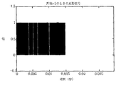
図5は図4のデータシンボルにデータが存在する確率が10%である信号の波形を示す例示画面であり、図6は光中継器で相関のために使用する基準信号の波形を示す例示画面であり、図7は図5と図6に図示された信号を相関させた結果出力された信号波形を示す例示画面である。 FIG. 5 is an exemplary screen showing a waveform of a signal having a 10% probability that data exists in the data symbol of FIG. 4, and FIG. 6 is an exemplary screen showing a waveform of a reference signal used for correlation in an optical repeater. FIG. 7 is an exemplary screen showing a signal waveform output as a result of correlating the signals shown in FIGS. 5 and 6.
図5に図示された信号がAP110から光中継器のメインドナー200を通じてリモートに伝えられれば、リモート250のカプラー265で信号の一部を抽出してスイッチングタイミング信号生成回路290に伝達する。スイッチングタイミング信号生成回路290では、図6に図示された基準信号を生成して、基準信号を図5に図示された入力信号と相関させれば、図7に図示された信号波形が得られる。
If the signal shown in FIG. 5 is transmitted remotely from the
ここで、図5に図示された入力信号は、0秒から0.015秒まで信号区間が存在するので、図6に図示された基準信号は入力信号が存在する信号区間で相関を遂行することができるように、0秒から0.015秒まで信号値を‘1’として有している。 Here, since the input signal illustrated in FIG. 5 has a signal interval from 0 second to 0.015 second, the reference signal illustrated in FIG. 6 performs correlation in the signal interval in which the input signal exists. So that the signal value is '1' from 0 second to 0.015 second.
一方、図4に図示されたように、1つのフレームはプリアンブルから始まるので、プリアンブルの位置を確認すれば、フレーム開始位置が分かる。プリアンブルはデータシンボルでなく、データシンボルが始まる時点を知らせてくれて伝送タイミングを同期化するために使われる信号であるので、プリアンブル信号は簡単な形態である‘1’の連続で構成されることができる。即ち、プリアンブル信号区間では、基準信号と信号値が同一であるので、図5に図示された入力信号と図6に図示された基準信号を相関させればプリアンブルが位置した時点で相関結果値が最大となり、この位置が各フレームの開始位置となる。したがって、図7に図示された信号波形で最大値と表れる位置がフレームの開始位置となる。 On the other hand, as shown in FIG. 4, since one frame starts from the preamble, the frame start position can be known by confirming the position of the preamble. Since the preamble is not a data symbol, but a signal used to synchronize the transmission timing by notifying the start time of the data symbol, the preamble signal should be composed of a continuous “1” in a simple form. Can do. That is, in the preamble signal section, the signal value is the same as that of the reference signal. Therefore, if the input signal shown in FIG. 5 is correlated with the reference signal shown in FIG. 6, the correlation result value is obtained when the preamble is located. This is the maximum, and this position becomes the start position of each frame. Therefore, the position where the maximum value appears in the signal waveform shown in FIG. 7 is the start position of the frame.
図4で前述したように、上りリンクと下りリンクを含むフレームの構造は予め定義されているので、フレームの開始位置を知ることになれば、フレームの各シンボルに定まった時間間隔を計算して上りリンクと下りリンクの開始点が計算できることになる。即ち、フレームは下りリンク区間から始まるので、フレームの開始位置が下りリンクの開始点となり、下りリンクの時間間隔にTTGを足した位置が上りリンクの開始点となる。したがって、図7の信号波形では最大値を有する0.005秒、0.01秒、0.015秒が各々フレームの開始位置となり、これを基準に計算された上りリンクと下りリンクの開始点が上り信号と下り信号の開始点となる。 As described above with reference to FIG. 4, the structure of the frame including the uplink and the downlink is defined in advance. Therefore, if the start position of the frame is known, the time interval determined for each symbol of the frame is calculated. Uplink and downlink start points can be calculated. That is, since the frame starts from the downlink section, the start position of the frame is the start point of the downlink, and the position obtained by adding TTG to the downlink time interval is the start point of the uplink. Therefore, in the signal waveform of FIG. 7, 0.005 seconds, 0.01 seconds, and 0.015 seconds having the maximum values are the start positions of the frames, respectively, and the start points of the uplink and the downlink calculated based on this are the reference points. This is the starting point for upstream and downstream signals.
スイッチングタイミング信号生成回路290では、下り信号と上り信号の開始点を基準にスイッチングタイミング信号を生成してスイッチを制御することになり、その結果、光中継器では下り信号と上り信号を仕分けて、各々の信号に対する伝送経路が選択的に提供できることになる。
In the switching timing
一方、前述したように、1つのフレームはプリアンブルから始まり、相関結果値がプリアンブルが位置した時間区間で最大になって、フレームの開始位置が分かるので、フレームの上りリンクと下りリンクを構成するデータシンボルの割合が変わったり、パイロットシンボルを使用しなくて、プリアンブルのみを使用する場合にも下り信号と上り信号を仕分けてスイッチングタイミング信号を生成することができる。 On the other hand, as described above, one frame starts from the preamble, and the correlation result value becomes the maximum in the time section where the preamble is located, so that the start position of the frame can be known. Therefore, the data constituting the uplink and downlink of the frame Even when only the preamble is used without changing the symbol ratio or using the pilot symbol, the switching timing signal can be generated by sorting the downlink signal and the uplink signal.
図8は、本発明の好ましい実施例に係るTDD方式とOFDM変調方式を用いる移動通信網の光中継器で伝送信号を分離するスイッチングタイミング信号生成方法を示す順序図である。 FIG. 8 is a flowchart illustrating a switching timing signal generation method for separating transmission signals by an optical repeater of a mobile communication network using a TDD scheme and an OFDM modulation scheme according to a preferred embodiment of the present invention.
図8に示すように、AP110からRF信号を伝送すれば、光中継器のメーンドナー200でこれを伝送されて光信号に変換した後、光通信ケーブルを介してリモート250に伝送する(S800)。リモート250では伝送された光信号をまたRF信号に変換してAT100に送出することになるが、リモート250の光電変換モジュール260とHPA270との間に位置したカプラー265でRF信号の一部を抽出してスイッチングタイミング信号生成回路290に伝達することになる(S802)。スイッチングタイミング信号生成回路290では、カプラー265から伝達受けた信号とスイッチングタイミング信号生成回路290の基準パルスジェネレータ360で生成した基準信号を相関させる(S804)。2つの信号を相関させた結果波形から最大値と表れる位置がRF信号のフレーム開始位置となるので、相関させた結果波形を分析してフレームの開始位置を判別することになる(S806)。
As shown in FIG. 8, if an RF signal is transmitted from the
TDD方式とOFDM変調方式を用いる信号は、図4で前述したように、フレーム構造が予め定義されているので、スイッチングタイミング信号生成回路290ではフレーム開始位置を基準にRF信号に含まれた下り信号と上り信号の開始点を計算する(S808)。下り信号と上り信号の開始点が計算されれば、これを用いて下り信号と上り信号を仕分けるためのスイッチングタイミング信号を生成してスイッチ275に伝達することになる(S810)。スイッチングタイミング信号がスイッチ275に伝えられれば、スイッチ275はスイッチングタイミング信号により下り信号と上り信号を仕分けることになり、スイッチの短絡を調節して各々の信号に対する経路を選択的に提供することになる(S812)。したがって、光中継器は、スイッチングタイミング信号により下り信号と上り信号が干渉することを防止し、下り信号の場合にはAT100に送出し、上り信号の場合にはAP110に伝達して、AP110とAT100の間で伝送信号を中継することになる。
Since the signal using the TDD scheme and the OFDM modulation scheme has a predefined frame structure as described above with reference to FIG. 4, the switching timing
以上の説明は、本発明を例示的に説明したことに過ぎないものであって、本発明が属する技術分野で通常の知識を有する者であれば、本発明の本質的な特性から外れない範囲で多様な変形が可能である。したがって、本明細書に開示された実施例は本発明を限定するためのものでなく、説明するためのものであり、このような実施例により本発明の思想と範囲が限るのではない。本発明の範囲は下記の請求範囲により解されなければならなくて、それと同等な範囲内にある全ての技術は本発明の権利範囲に含まれることと解されているべきである。 The above description is merely illustrative of the present invention, and a person having ordinary knowledge in the technical field to which the present invention belongs does not depart from the essential characteristics of the present invention. Various modifications are possible. Accordingly, the embodiments disclosed herein are not intended to limit the present invention but to explain them, and the spirit and scope of the present invention are not limited by such embodiments. The scope of the present invention should be understood by the following claims, and it should be understood that all technologies within the scope equivalent thereto are included in the scope of the present invention.
Claims (29)
(a)前記APから伝送されたRF信号を前記光中継器のメインドナーを通じて前記光中継器のリモートに伝達するステップと、
(b)前記リモートのカプラーで前記RF信号の一部を抽出して前記リモートのスイッチングタイミング信号生成回路に伝達するステップと、
(c)前記カプラーで抽出したRF信号と前記スイッチングタイミング信号生成回路で生成した基準信号を相関させるステップと、
(d)前記相関結果値を分析して前記RF信号のフレーム開始位置を判別するステップと、
(e)前記フレーム開始位置を基準に、前記RF信号に含まれた下り信号と上り信号の開始点を計算するステップと、
(f)前記下り信号と前記上り信号の開始点情報を用いてスイッチングタイミング信号を生成して前記リモートのスイッチに伝達するステップと、
(g)前記スイッチは、前記スイッチングタイミング信号により前記下り信号と前記上り信号を仕分けて伝送するステップと、
を含むことを特徴とするTDD方式とOFDM変調方式を用いる移動通信網の光中継器で伝送信号を分離するスイッチングタイミング信号生成方法。Using a TDD (Time Division Duplex) method and an OFDM (Orthogonal Frequency Division Multiplexing) modulation method, a transmission signal is transmitted by the optical repeater of a mobile communication system including an AP (Access Point), an AT (Access Terminal), and an optical repeater. A switching timing signal generation method for separating,
(A) transmitting an RF signal transmitted from the AP to a remote of the optical repeater through a main donor of the optical repeater;
(B) extracting a part of the RF signal with the remote coupler and transmitting it to the remote switching timing signal generation circuit;
(C) correlating the RF signal extracted by the coupler with the reference signal generated by the switching timing signal generation circuit;
(D) analyzing the correlation result value to determine a frame start position of the RF signal;
(E) calculating a start point of a downlink signal and an uplink signal included in the RF signal based on the frame start position;
(F) generating a switching timing signal using the downlink signal and the starting point information of the uplink signal and transmitting the switching timing signal to the remote switch;
(G) The switch sorts and transmits the downlink signal and the uplink signal according to the switching timing signal;
A switching timing signal generation method for separating a transmission signal by an optical repeater of a mobile communication network using a TDD scheme and an OFDM modulation scheme.
前記相関結果値を分析して前記相関結果値が最大の位置を前記RF信号のフレーム開始位置と決定することを特徴とする請求項1記載のTDD方式とOFDM変調方式を用いる移動通信網の光中継器で伝送信号を分離するスイッチングタイミング信号生成方法。The step (d) includes:
2. The light of a mobile communication network using a TDD scheme and an OFDM modulation scheme according to claim 1, wherein the correlation result value is analyzed to determine a position where the correlation result value is maximum as a frame start position of the RF signal. A switching timing signal generation method for separating transmission signals by a repeater.
前記フレームの開始位置を前記下りリンクの開始点と決定し、前記下りリンクの時間間隔に前記TTGを足した位置を前記上りリンクの開始点と決定して、前記下りリンクの開始点を前記下り信号の開始点と設定し、前記上りリンクの開始点を前記上り信号の開始点と設定することを特徴とする請求項4記載のTDD方式とOFDM変調方式を用いる移動通信網の光中継器で伝送信号を分離するスイッチングタイミング信号生成方法。The step (e) includes:
The start position of the frame is determined as the downlink start point, the position obtained by adding the TTG to the downlink time interval is determined as the uplink start point, and the downlink start point is determined as the downlink start point. 5. The optical repeater of a mobile communication network using a TDD scheme and an OFDM modulation scheme according to claim 4, wherein a signal start point is set, and the uplink start point is set as the uplink signal start point. A switching timing signal generation method for separating transmission signals.
前記APから伝送されたRF信号を光信号に変換してリモートに伝送し、前記リモートから伝送された光信号をRF信号に変換して前記APに伝送する前記光中継器のメインドナーと、
前記メインドナーから伝送された光信号をRF信号に変換して前記ATに伝送し、前記ATから伝送されたRF信号を光信号に変換して前記メインドナーに伝送する前記光中継器のリモートと、
前記メインドナーから前記リモートに伝送されたRF信号の一部を抽出して自体内で生成した基準信号と前記抽出したRF信号を相関させ、前記相関結果値を分析して前記抽出したRF信号のフレーム開始位置を判別し、前記フレーム開始位置を基準に前記抽出したRF信号に含まれた下り信号と上り信号の開始点を計算し、前記計算された下り信号と上り信号の開始点情報を用いてスイッチングタイミング信号を生成して前記リモートのスイッチに伝達するスイッチングタイミング信号生成回路と、
を含むことを特徴とするTDD方式とOFDM変調方式を用いる移動通信網の光中継器で伝送信号を分離するスイッチングタイミング信号生成システム。In an optical repeater of a mobile communication network using a TDD (Time Division Duplex) method and an OFDM (Orthogonal Frequency Division Multiplexing) modulation method, an RF signal transmitted from an AP (Access Point) and an AT (Access Terminal) is transmitted as a downlink signal and an uplink signal. A switching timing signal generation system that separates signals,
A main donor of the optical repeater that converts an RF signal transmitted from the AP into an optical signal and transmits the signal remotely, converts an optical signal transmitted from the remote into an RF signal and transmits the signal to the AP;
An optical repeater that converts an optical signal transmitted from the main donor into an RF signal and transmits it to the AT, converts an RF signal transmitted from the AT into an optical signal, and transmits the optical signal to the main donor; ,
A part of the RF signal transmitted from the main donor to the remote is extracted, the reference signal generated within itself is correlated with the extracted RF signal, the correlation result value is analyzed, and the extracted RF signal A frame start position is determined, a start point of a downlink signal and an uplink signal included in the extracted RF signal is calculated based on the frame start position, and the start point information of the calculated downlink signal and uplink signal is used. A switching timing signal generating circuit that generates a switching timing signal and transmits the switching timing signal to the remote switch;
A switching timing signal generation system for separating a transmission signal by an optical repeater of a mobile communication network using a TDD scheme and an OFDM modulation scheme.
前記光中継器のリモートに含まれたカプラーにおいて、前記光中継器のメインドナーから前記リモートに伝送されたRF信号の一部を抽出すれば、前記抽出したRF信号を伝達受けてレベルディテクタ(Level Detector)と可変利得増幅器(VGA:Variable Gain Amplifier)に分配する分配器(Divider)と、
前記分配器から分配受けた前記抽出したRF信号のレベルを測定して前記可変利得増幅器に伝達するレベルディテクタと、
前記レベルディテクタで測定されたレベル値を入力受けて前記抽出したRF信号を一定のレベルに維持させて出力する可変利得増幅器と、
前記可変利得増幅器から入力受けた前記抽出したRF信号の変化量を鎖状(Linear)スケールからデシベル(dB)スケールに変えた後、パルスジェネレータ(Pulse-Shape Generator)に伝達するログスケール増幅器(Log-Scale Amplifier)と、
前記ログスケール増幅器から入力受けた前記抽出したRF信号を用いてパルス波形信号を生成して比較器(Comparator)に伝達するパルスジェネレータと、
前記パルスジェネレータで生成された前記パルス波形信号と相関させて、前記抽出したRF信号のフレーム開始位置を判別するための基準パルス波形信号を生成して前記比較器に伝達する基準パルスジェネレータ(Reference Pulse-Shape Generator)と、
前記パルスジェネレータと前記基準パルスジェネレータから伝達受けた信号を相関させて、その結果値をタイミングコントローラ(Timing Controller)に伝達する比較器と、
前記比較器から伝達受けた前記結果値を分析して前記抽出されたRF信号のフレーム開始位置を判別し、判別した前記フレーム開始位置を基準に前記抽出されたRF信号に含まれた下り信号と上り信号の開始点を計算し、前記計算された下り信号と上り信号の開始点情報を用いてスイッチングタイミング信号を生成して前記リモートのスイッチに伝達するタイミングコントローラと、
前記パルスジェネレータで生成された前記パルス波形信号の位相情報を前記比較器から伝達受けて前記基準パルス波形信号の位相を同調させる位相同調回路(Phase Tuning Circuit)と、
を含むことを特徴とするTDD方式とOFDM変調方式を用いる移動通信網の光中継器において、RF信号を下り信号と上り信号に分離するスイッチングタイミング信号を生成するスイッチングタイミング信号生成回路。In an optical repeater of a mobile communication network using a TDD (Time Division Duplex) method and an OFDM (Orthogonal Frequency Division Multiplexing) modulation method, an RF signal transmitted from an AP (Access Point) and an AT (Access Terminal) is transmitted as a downlink signal and an uplink signal. A switching timing signal generation circuit for generating a switching timing signal to be separated into signals,
If a part of the RF signal transmitted to the remote from the main donor of the optical repeater is extracted in the coupler included in the remote of the optical repeater, the extracted RF signal is transmitted and received to receive a level detector (Level Detector and a variable gain amplifier (VGA: Variable Gain Amplifier) distributor (Divider),
A level detector that measures the level of the extracted RF signal received from the distributor and transmits the level to the variable gain amplifier;
A variable gain amplifier that receives the level value measured by the level detector and outputs the extracted RF signal while maintaining it at a constant level;
A log scale amplifier (Log) that changes the amount of change in the extracted RF signal received from the variable gain amplifier from a linear scale to a decibel (dB) scale, and then transmits the change to a pulse generator (Pulse-Shape Generator) -Scale Amplifier)
A pulse generator that generates a pulse waveform signal using the extracted RF signal received from the log scale amplifier and transmits the pulse waveform signal to a comparator;
A reference pulse generator (Reference Pulse) that correlates with the pulse waveform signal generated by the pulse generator to generate a reference pulse waveform signal for determining a frame start position of the extracted RF signal and transmits the reference pulse waveform signal to the comparator -Shape Generator)
A comparator that correlates signals received from the pulse generator and the reference pulse generator and transmits a result value to a timing controller;
Analyzing the result value received from the comparator to determine a frame start position of the extracted RF signal; and a downlink signal included in the extracted RF signal based on the determined frame start position; A timing controller that calculates an upstream signal start point, generates a switching timing signal using the calculated downstream signal and upstream signal start point information, and transmits the switching timing signal to the remote switch;
A phase tuning circuit that receives phase information of the pulse waveform signal generated by the pulse generator from the comparator and tunes the phase of the reference pulse waveform signal;
A switching timing signal generation circuit for generating a switching timing signal for separating an RF signal into a downlink signal and an uplink signal in an optical repeater of a mobile communication network using a TDD scheme and an OFDM modulation scheme.
Applications Claiming Priority (2)
| Application Number | Priority Date | Filing Date | Title |
|---|---|---|---|
| KR1020040059582A KR100590486B1 (en) | 2004-07-29 | 2004-07-29 | Method and System for Generating Switching Timing Signal for Separating Transmitting and Receiving Signal in Optical Repeater of Mobile Telecommunication Network Using TDD and ODFM Modulation |
| PCT/KR2005/002484 WO2006011778A1 (en) | 2004-07-29 | 2005-07-29 | Method and system for generating switching timing signal for separating transmitting and receving signal in optical repeater of mobile telecommunication network using tdd and ofdm modulation |
Publications (2)
| Publication Number | Publication Date |
|---|---|
| JP2008508781A JP2008508781A (en) | 2008-03-21 |
| JP4435231B2 true JP4435231B2 (en) | 2010-03-17 |
Family
ID=35786476
Family Applications (1)
| Application Number | Title | Priority Date | Filing Date |
|---|---|---|---|
| JP2007523488A Expired - Fee Related JP4435231B2 (en) | 2004-07-29 | 2005-07-29 | Switching timing signal generation method and system for separating transmission signals by optical repeater of mobile communication network using TDD method and OFDM modulation method |
Country Status (6)
| Country | Link |
|---|---|
| US (1) | US7899084B2 (en) |
| EP (1) | EP1771987B1 (en) |
| JP (1) | JP4435231B2 (en) |
| KR (1) | KR100590486B1 (en) |
| CN (1) | CN101019398B (en) |
| WO (1) | WO2006011778A1 (en) |
Cited By (1)
| Publication number | Priority date | Publication date | Assignee | Title |
|---|---|---|---|---|
| US10735083B2 (en) | 2018-01-25 | 2020-08-04 | Kabushiki Kaisha Toshiba | Communication repeater device, control method, and computer program product |
Families Citing this family (158)
| Publication number | Priority date | Publication date | Assignee | Title |
|---|---|---|---|---|
| US6904079B2 (en) * | 2000-02-08 | 2005-06-07 | Ipr Licensing, Inc. | Access channel structure for wireless communication system |
| KR20050010951A (en) | 2002-06-21 | 2005-01-28 | 위데피, 인코포레이티드 | Wireless local area network repeater |
| US8885688B2 (en) | 2002-10-01 | 2014-11-11 | Qualcomm Incorporated | Control message management in physical layer repeater |
| KR100664583B1 (en) * | 2004-08-16 | 2007-01-04 | 주식회사 쏠리테크 | Network system of base station and optic repeater in a mobile internet service |
| CN101636930A (en) * | 2006-03-31 | 2010-01-27 | 高通股份有限公司 | Be used for the enhanced physical layer repeater operated in the WiMAX system |
| KR100762637B1 (en) * | 2006-05-03 | 2007-10-01 | 삼성전자주식회사 | Bidirectional radio-over-fiber link apparatus using one wavelength for wireless system using tdd scheme |
| US8472767B2 (en) | 2006-05-19 | 2013-06-25 | Corning Cable Systems Llc | Fiber optic cable and fiber optic cable assembly for wireless access |
| WO2008034354A1 (en) * | 2006-08-07 | 2008-03-27 | Huawei Technologies Co., Ltd. | A system, apparatus and method for transmitting digital subscriber signaling |
| KR100799679B1 (en) * | 2006-08-30 | 2008-01-30 | 주식회사 휴텍이일 | Microwave repeater using frequency division duplexing and time division duplexing method |
| KR100819257B1 (en) * | 2006-08-31 | 2008-04-02 | 삼성전자주식회사 | Radio Over Fiber System and Method for Controlling Transmission Time |
| US7787823B2 (en) | 2006-09-15 | 2010-08-31 | Corning Cable Systems Llc | Radio-over-fiber (RoF) optical fiber cable system with transponder diversity and RoF wireless picocellular system using same |
| RU2444159C2 (en) | 2006-09-21 | 2012-02-27 | Квэлкомм Инкорпорейтед | Method and device for suppression of oscillations between repeaters |
| US7848654B2 (en) | 2006-09-28 | 2010-12-07 | Corning Cable Systems Llc | Radio-over-fiber (RoF) wireless picocellular system with combined picocells |
| JP4875164B2 (en) * | 2006-10-26 | 2012-02-15 | クゥアルコム・インコーポレイテッド | Repeater technology for multiple inputs and multiple outputs using beamformers |
| KR100770883B1 (en) * | 2006-11-14 | 2007-10-26 | 삼성전자주식회사 | Radio over fiber system of tdd type and method for controlling transmission time |
| CN101192875B (en) * | 2006-11-27 | 2011-05-25 | 上海无线通信研究中心 | Uplink orthogonal reference signal distribution method for universal land wireless access system |
| KR100842533B1 (en) * | 2006-12-13 | 2008-07-01 | 삼성전자주식회사 | Radio over fiber rink based on time division duplex |
| KR100842534B1 (en) | 2006-12-14 | 2008-07-01 | 삼성전자주식회사 | Method and System Generating Switching Control Signal for Separating Transmission Signal in Optical Repeater Using TDD |
| US8873585B2 (en) | 2006-12-19 | 2014-10-28 | Corning Optical Communications Wireless Ltd | Distributed antenna system for MIMO technologies |
| KR101306726B1 (en) * | 2006-12-22 | 2013-09-10 | 엘지전자 주식회사 | Method Of Allocating Symbol For Pilot Signal, And Method For Transmitting and Receiving Signals Using The Subframe By The Same, In Mobile Communication System |
| KR100856196B1 (en) | 2007-01-03 | 2008-09-03 | 삼성전자주식회사 | Method and System for Controlling Remote in Optical Repeater Using TDD |
| US8111998B2 (en) | 2007-02-06 | 2012-02-07 | Corning Cable Systems Llc | Transponder systems and methods for radio-over-fiber (RoF) wireless picocellular systems |
| KR100866217B1 (en) | 2007-03-28 | 2008-10-30 | 삼성전자주식회사 | Method and apparatus constructing system delay time and frame length using time division duplexing |
| KR20080093746A (en) * | 2007-04-18 | 2008-10-22 | 삼성전자주식회사 | Radio over optical fiver remote station and cable relaying method using low noise amplifier as common amplifier of up and down link |
| US20100054746A1 (en) | 2007-07-24 | 2010-03-04 | Eric Raymond Logan | Multi-port accumulator for radio-over-fiber (RoF) wireless picocellular systems |
| US7860406B2 (en) * | 2007-09-14 | 2010-12-28 | Alcatel-Lucent Usa Inc. | PMD insensitive direct-detection optical OFDM systems using self-polarization diversity |
| US8175459B2 (en) | 2007-10-12 | 2012-05-08 | Corning Cable Systems Llc | Hybrid wireless/wired RoF transponder and hybrid RoF communication system using same |
| JP2011502386A (en) * | 2007-10-17 | 2011-01-20 | ゼットティーイー ユー.エス.エー. インコーポレイテッド | OFDM / OFDMA frame structure for communication system |
| US8369301B2 (en) | 2007-10-17 | 2013-02-05 | Zte (Usa) Inc. | OFDM/OFDMA frame structure for communication systems |
| KR101450875B1 (en) | 2007-11-15 | 2014-10-24 | 삼성전자주식회사 | The decision method of tdd control in fiber relaying wireless communication system |
| US8644844B2 (en) | 2007-12-20 | 2014-02-04 | Corning Mobileaccess Ltd. | Extending outdoor location based services and applications into enclosed areas |
| DE102008017881B9 (en) | 2008-04-09 | 2012-11-08 | Andrew Wireless Systems Gmbh | TDD repeater for a wireless network and method for operating such a repeater |
| EP2301165B1 (en) * | 2008-06-06 | 2020-09-09 | TRC Companies, Inc. | Intelligent power system and methods for its application |
| US8676056B2 (en) * | 2008-06-20 | 2014-03-18 | Xieon Networks S.A.R.L. | Subcarrier multiplex system |
| JP5480916B2 (en) | 2009-02-03 | 2014-04-23 | コーニング ケーブル システムズ リミテッド ライアビリティ カンパニー | Fiber optic based distributed antenna system, components, and related methods for calibration thereof |
| WO2010090999A1 (en) | 2009-02-03 | 2010-08-12 | Corning Cable Systems Llc | Optical fiber-based distributed antenna systems, components, and related methods for monitoring and configuring thereof |
| US9673904B2 (en) | 2009-02-03 | 2017-06-06 | Corning Optical Communications LLC | Optical fiber-based distributed antenna systems, components, and related methods for calibration thereof |
| US8548330B2 (en) | 2009-07-31 | 2013-10-01 | Corning Cable Systems Llc | Sectorization in distributed antenna systems, and related components and methods |
| KR101752409B1 (en) * | 2009-08-25 | 2017-06-29 | 엘지전자 주식회사 | Method of transmitting and receiving control information in a wireless system |
| US8280259B2 (en) | 2009-11-13 | 2012-10-02 | Corning Cable Systems Llc | Radio-over-fiber (RoF) system for protocol-independent wired and/or wireless communication |
| US8886755B1 (en) | 2009-12-09 | 2014-11-11 | Marvell International Ltd. | Method and apparatus for facilitating simultaneous transmission from multiple stations |
| US8275265B2 (en) | 2010-02-15 | 2012-09-25 | Corning Cable Systems Llc | Dynamic cell bonding (DCB) for radio-over-fiber (RoF)-based networks and communication systems and related methods |
| US9525488B2 (en) | 2010-05-02 | 2016-12-20 | Corning Optical Communications LLC | Digital data services and/or power distribution in optical fiber-based distributed communications systems providing digital data and radio frequency (RF) communications services, and related components and methods |
| US20110268446A1 (en) | 2010-05-02 | 2011-11-03 | Cune William P | Providing digital data services in optical fiber-based distributed radio frequency (rf) communications systems, and related components and methods |
| US10667148B1 (en) | 2010-05-28 | 2020-05-26 | Cohere Technologies, Inc. | Methods of operating and implementing wireless communications systems |
| US9130638B2 (en) | 2011-05-26 | 2015-09-08 | Cohere Technologies, Inc. | Modulation and equalization in an orthonormal time-frequency shifting communications system |
| US10681568B1 (en) | 2010-05-28 | 2020-06-09 | Cohere Technologies, Inc. | Methods of data channel characterization and uses thereof |
| US9444514B2 (en) | 2010-05-28 | 2016-09-13 | Cohere Technologies, Inc. | OTFS methods of data channel characterization and uses thereof |
| US11943089B2 (en) | 2010-05-28 | 2024-03-26 | Cohere Technologies, Inc. | Modulation and equalization in an orthonormal time-shifting communications system |
| US9071286B2 (en) | 2011-05-26 | 2015-06-30 | Cohere Technologies, Inc. | Modulation and equalization in an orthonormal time-frequency shifting communications system |
| US9071285B2 (en) | 2011-05-26 | 2015-06-30 | Cohere Technologies, Inc. | Modulation and equalization in an orthonormal time-frequency shifting communications system |
| EP2606707A1 (en) | 2010-08-16 | 2013-06-26 | Corning Cable Systems LLC | Remote antenna clusters and related systems, components, and methods supporting digital data signal propagation between remote antenna units |
| CN102386954B (en) * | 2010-09-03 | 2014-05-07 | 华为技术有限公司 | Data transmission method, access point equipment and terminal |
| US9252874B2 (en) | 2010-10-13 | 2016-02-02 | Ccs Technology, Inc | Power management for remote antenna units in distributed antenna systems |
| EP2678972B1 (en) | 2011-02-21 | 2018-09-05 | Corning Optical Communications LLC | Providing digital data services as electrical signals and radio-frequency (rf) communications over optical fiber in distributed communications systems, and related components and methods |
| WO2012142586A1 (en) | 2011-04-15 | 2012-10-18 | Power Tagging Technologies, Inc. | System and method for single and multi zonal optimization of utility services delivery and utilization |
| WO2012148940A1 (en) | 2011-04-29 | 2012-11-01 | Corning Cable Systems Llc | Systems, methods, and devices for increasing radio frequency (rf) power in distributed antenna systems |
| EP2702710A4 (en) | 2011-04-29 | 2014-10-29 | Corning Cable Sys Llc | Determining propagation delay of communications in distributed antenna systems, and related components, systems and methods |
| US9059842B2 (en) | 2011-06-09 | 2015-06-16 | Astrolink International Llc | System and method for grid based cyber security |
| WO2013020053A1 (en) | 2011-08-03 | 2013-02-07 | Power Tagging Technologies, Inc. | System and methods for synchronizing edge devices on channels without carrier sense |
| CN102281229B (en) * | 2011-08-24 | 2017-12-05 | 中兴通讯股份有限公司 | The collocation method and device of a kind of conversion interval in communication system |
| TWI462514B (en) * | 2011-09-29 | 2014-11-21 | Inst Information Industry | Time division duplex orthogonal frequency division multiplexing distributed antenna system, base station and remote access unit |
| EP2832012A1 (en) | 2012-03-30 | 2015-02-04 | Corning Optical Communications LLC | Reducing location-dependent interference in distributed antenna systems operating in multiple-input, multiple-output (mimo) configuration, and related components, systems, and methods |
| WO2013162988A1 (en) | 2012-04-25 | 2013-10-31 | Corning Cable Systems Llc | Distributed antenna system architectures |
| US10411843B2 (en) | 2012-06-25 | 2019-09-10 | Cohere Technologies, Inc. | Orthogonal time frequency space communication system compatible with OFDM |
| US10469215B2 (en) | 2012-06-25 | 2019-11-05 | Cohere Technologies, Inc. | Orthogonal time frequency space modulation system for the Internet of Things |
| US10090972B2 (en) | 2012-06-25 | 2018-10-02 | Cohere Technologies, Inc. | System and method for two-dimensional equalization in an orthogonal time frequency space communication system |
| US9929783B2 (en) * | 2012-06-25 | 2018-03-27 | Cohere Technologies, Inc. | Orthogonal time frequency space modulation system |
| WO2014024192A1 (en) | 2012-08-07 | 2014-02-13 | Corning Mobile Access Ltd. | Distribution of time-division multiplexed (tdm) management services in a distributed antenna system, and related components, systems, and methods |
| US9455784B2 (en) | 2012-10-31 | 2016-09-27 | Corning Optical Communications Wireless Ltd | Deployable wireless infrastructures and methods of deploying wireless infrastructures |
| US9077508B2 (en) * | 2012-11-15 | 2015-07-07 | Mitsubishi Electric Research Laboratories, Inc. | Adaptively coding and modulating signals transmitted via nonlinear channels |
| CN105308876B (en) | 2012-11-29 | 2018-06-22 | 康宁光电通信有限责任公司 | Remote unit antennas in distributing antenna system combines |
| US9647758B2 (en) | 2012-11-30 | 2017-05-09 | Corning Optical Communications Wireless Ltd | Cabling connectivity monitoring and verification |
| US10097240B2 (en) | 2013-02-19 | 2018-10-09 | Astrolink International, Llc | System and method for inferring schematic and topological properties of an electrical distribution grid |
| US9438312B2 (en) | 2013-06-06 | 2016-09-06 | Astrolink International Llc | System and method for inferring schematic relationships between load points and service transformers |
| CN105452951B (en) | 2013-06-12 | 2018-10-19 | 康宁光电通信无线公司 | Voltage type optical directional coupler |
| EP3008828B1 (en) | 2013-06-12 | 2017-08-09 | Corning Optical Communications Wireless Ltd. | Time-division duplexing (tdd) in distributed communications systems, including distributed antenna systems (dass) |
| MX357831B (en) | 2013-06-13 | 2018-07-26 | Astrolink Int Llc | Non-technical losses in a power distribution grid. |
| US10749571B2 (en) | 2013-06-13 | 2020-08-18 | Trc Companies, Inc. | System and methods for inferring the feeder and phase powering an on-grid transmitter |
| US9247543B2 (en) | 2013-07-23 | 2016-01-26 | Corning Optical Communications Wireless Ltd | Monitoring non-supported wireless spectrum within coverage areas of distributed antenna systems (DASs) |
| US9661781B2 (en) | 2013-07-31 | 2017-05-23 | Corning Optical Communications Wireless Ltd | Remote units for distributed communication systems and related installation methods and apparatuses |
| US9385810B2 (en) | 2013-09-30 | 2016-07-05 | Corning Optical Communications Wireless Ltd | Connection mapping in distributed communication systems |
| CN110071791B (en) * | 2013-10-30 | 2022-04-19 | 安德鲁无线系统有限公司 | Switching subsystem for distributed antenna system utilizing time division duplexing |
| US9825678B2 (en) | 2013-11-26 | 2017-11-21 | Marvell World Trade Ltd. | Uplink multi-user multiple input multiple output for wireless local area network |
| WO2015081269A1 (en) | 2013-11-27 | 2015-06-04 | Marvell Semiconductor, Inc. | Sounding and tone block allocation for orthogonal frequency division multiple access (ofdma) in wireless local area networks |
| US9166660B2 (en) | 2013-11-27 | 2015-10-20 | Marvell World Trade Ltd. | Uplink multi-user multiple input multiple output beamforming |
| US9178635B2 (en) | 2014-01-03 | 2015-11-03 | Corning Optical Communications Wireless Ltd | Separation of communication signal sub-bands in distributed antenna systems (DASs) to reduce interference |
| US9775123B2 (en) | 2014-03-28 | 2017-09-26 | Corning Optical Communications Wireless Ltd. | Individualized gain control of uplink paths in remote units in a distributed antenna system (DAS) based on individual remote unit contribution to combined uplink power |
| EP3138226B1 (en) | 2014-05-02 | 2020-07-08 | NXP USA, Inc. | Multiple user allocation signaling in a wireless communication network |
| US9357551B2 (en) | 2014-05-30 | 2016-05-31 | Corning Optical Communications Wireless Ltd | Systems and methods for simultaneous sampling of serial digital data streams from multiple analog-to-digital converters (ADCS), including in distributed antenna systems |
| US9525472B2 (en) | 2014-07-30 | 2016-12-20 | Corning Incorporated | Reducing location-dependent destructive interference in distributed antenna systems (DASS) operating in multiple-input, multiple-output (MIMO) configuration, and related components, systems, and methods |
| JP6352729B2 (en) * | 2014-08-26 | 2018-07-04 | 株式会社東芝 | Repeater system, repeater device, and timing signal generation method |
| US9730228B2 (en) | 2014-08-29 | 2017-08-08 | Corning Optical Communications Wireless Ltd | Individualized gain control of remote uplink band paths in a remote unit in a distributed antenna system (DAS), based on combined uplink power level in the remote unit |
| US9602210B2 (en) | 2014-09-24 | 2017-03-21 | Corning Optical Communications Wireless Ltd | Flexible head-end chassis supporting automatic identification and interconnection of radio interface modules and optical interface modules in an optical fiber-based distributed antenna system (DAS) |
| US10659163B2 (en) | 2014-09-25 | 2020-05-19 | Corning Optical Communications LLC | Supporting analog remote antenna units (RAUs) in digital distributed antenna systems (DASs) using analog RAU digital adaptors |
| US9420542B2 (en) | 2014-09-25 | 2016-08-16 | Corning Optical Communications Wireless Ltd | System-wide uplink band gain control in a distributed antenna system (DAS), based on per band gain control of remote uplink paths in remote units |
| BR112017009037A2 (en) | 2014-10-30 | 2018-07-03 | Astrolink International Llc | system, method and apparatus for network location |
| PE20171123A1 (en) | 2014-10-30 | 2017-08-08 | Astrolink Int Llc | SYSTEM AND METHODS TO ASSIGN INTERVALS AND RESOLVE INTERVAL CONFLICTS IN AN ELECTRICAL DISTRIBUTION NETWORK |
| WO2016071902A1 (en) | 2014-11-03 | 2016-05-12 | Corning Optical Communications Wireless Ltd. | Multi-band monopole planar antennas configured to facilitate improved radio frequency (rf) isolation in multiple-input multiple-output (mimo) antenna arrangement |
| WO2016075696A1 (en) | 2014-11-13 | 2016-05-19 | Corning Optical Communications Wireless Ltd. | Analog distributed antenna systems (dass) supporting distribution of digital communications signals interfaced from a digital signal source and analog radio frequency (rf) communications signals |
| US9729267B2 (en) | 2014-12-11 | 2017-08-08 | Corning Optical Communications Wireless Ltd | Multiplexing two separate optical links with the same wavelength using asymmetric combining and splitting |
| WO2016098111A1 (en) | 2014-12-18 | 2016-06-23 | Corning Optical Communications Wireless Ltd. | Digital- analog interface modules (da!ms) for flexibly.distributing digital and/or analog communications signals in wide-area analog distributed antenna systems (dass) |
| EP3235336A1 (en) | 2014-12-18 | 2017-10-25 | Corning Optical Communications Wireless Ltd. | Digital interface modules (dims) for flexibly distributing digital and/or analog communications signals in wide-area analog distributed antenna systems (dass) |
| US20160249365A1 (en) | 2015-02-19 | 2016-08-25 | Corning Optical Communications Wireless Ltd. | Offsetting unwanted downlink interference signals in an uplink path in a distributed antenna system (das) |
| US9681313B2 (en) | 2015-04-15 | 2017-06-13 | Corning Optical Communications Wireless Ltd | Optimizing remote antenna unit performance using an alternative data channel |
| US10090973B2 (en) | 2015-05-11 | 2018-10-02 | Cohere Technologies, Inc. | Multiple access in an orthogonal time frequency space communication system |
| WO2016183230A1 (en) | 2015-05-11 | 2016-11-17 | Cohere Technologies | Systems and methods for symplectic orthogonal time frequency shifting modulation and transmission of data |
| US10574317B2 (en) | 2015-06-18 | 2020-02-25 | Cohere Technologies, Inc. | System and method for providing wireless communication services using configurable broadband infrastructure shared among multiple network operators |
| WO2017003952A1 (en) | 2015-06-27 | 2017-01-05 | Cohere Technologies, Inc. | Orthogonal time frequency space communication system compatible with ofdm |
| US10693581B2 (en) | 2015-07-12 | 2020-06-23 | Cohere Technologies, Inc. | Orthogonal time frequency space modulation over a plurality of narrow band subcarriers |
| US9948349B2 (en) | 2015-07-17 | 2018-04-17 | Corning Optical Communications Wireless Ltd | IOT automation and data collection system |
| EP3342068A1 (en) * | 2015-08-24 | 2018-07-04 | Telefonaktiebolaget LM Ericsson (PUBL) | Control of an optical transmitter in a radio over fibre system |
| CN108770382B (en) | 2015-09-07 | 2022-01-14 | 凝聚技术公司 | Multiple access method using orthogonal time frequency space modulation |
| US10560214B2 (en) | 2015-09-28 | 2020-02-11 | Corning Optical Communications LLC | Downlink and uplink communication path switching in a time-division duplex (TDD) distributed antenna system (DAS) |
| US9647752B2 (en) | 2015-10-13 | 2017-05-09 | Telefonaktiebolaget Lm Ericsson (Publ) | Antenna switch control method for analog radio over fiber systems |
| CN108781160B (en) | 2015-11-18 | 2022-04-29 | 凝聚技术公司 | Quadrature time frequency space modulation technique |
| EP3387748B1 (en) | 2015-12-09 | 2022-03-09 | Cohere Technologies, Inc. | Pilot packing using complex orthogonal functions |
| CN115694764A (en) | 2016-02-25 | 2023-02-03 | 凝聚技术公司 | Reference signal encapsulation for wireless communication |
| US10693692B2 (en) | 2016-03-23 | 2020-06-23 | Cohere Technologies, Inc. | Receiver-side processing of orthogonal time frequency space modulated signals |
| CN109845102B (en) | 2016-03-31 | 2023-07-28 | 凝聚技术公司 | Channel acquisition using orthogonal time-frequency space modulated pilot signals |
| US10236924B2 (en) | 2016-03-31 | 2019-03-19 | Corning Optical Communications Wireless Ltd | Reducing out-of-channel noise in a wireless distribution system (WDS) |
| US9667307B1 (en) | 2016-03-31 | 2017-05-30 | Cohere Technologies | Wireless telecommunications system for high-mobility applications |
| CN109196812B (en) | 2016-04-01 | 2021-03-09 | 科希尔技术股份有限公司 | Tomlinson-Harashima precoding method and device in orthogonal time-frequency space communication system |
| CN113726700A (en) | 2016-04-01 | 2021-11-30 | 凝聚技术公司 | Iterative two-dimensional equalization of orthogonal time-frequency space modulated signals |
| WO2017201467A1 (en) | 2016-05-20 | 2017-11-23 | Cohere Technologies | Iterative channel estimation and equalization with superimposed reference signals |
| EP3497907A4 (en) | 2016-08-12 | 2020-03-04 | Cohere Technologies, Inc. | Localized equalization for channels with intercarrier interference |
| CN109804561B (en) | 2016-08-12 | 2023-07-21 | 凝聚技术公司 | Multiuser multiplexing of orthogonal time-frequency space signals |
| EP3497799A4 (en) | 2016-08-12 | 2020-04-15 | Cohere Technologies, Inc. | Iterative multi-level equalization and decoding |
| US11310000B2 (en) | 2016-09-29 | 2022-04-19 | Cohere Technologies, Inc. | Transport block segmentation for multi-level codes |
| US10965348B2 (en) | 2016-09-30 | 2021-03-30 | Cohere Technologies, Inc. | Uplink user resource allocation for orthogonal time frequency space modulation |
| WO2018106731A1 (en) | 2016-12-05 | 2018-06-14 | Cohere Technologies | Fixed wireless access using orthogonal time frequency space modulation |
| EP3566379A4 (en) | 2017-01-09 | 2020-09-09 | Cohere Technologies, Inc. | Pilot scrambling for channel estimation |
| WO2018140837A1 (en) | 2017-01-27 | 2018-08-02 | Cohere Technologies | Variable beamwidth multiband antenna |
| US10568143B2 (en) | 2017-03-28 | 2020-02-18 | Cohere Technologies, Inc. | Windowed sequence for random access method and apparatus |
| EP3610582A4 (en) | 2017-04-11 | 2021-01-06 | Cohere Technologies, Inc. | Digital communication using dispersed orthogonal time frequency space modulated signals |
| EP3613243B1 (en) | 2017-04-21 | 2022-08-24 | Cohere Technologies, Inc. | Communication techniques using quasi-static properties of wireless channels |
| WO2018200567A1 (en) | 2017-04-24 | 2018-11-01 | Cohere Technologies | Multibeam antenna designs and operation |
| US11063804B2 (en) | 2017-04-24 | 2021-07-13 | Cohere Technologies, Inc. | Digital communication using lattice division multiplexing |
| JP6602813B2 (en) * | 2017-04-24 | 2019-11-06 | 株式会社東芝 | Communication relay system and method |
| EP3652907A4 (en) | 2017-07-12 | 2021-04-07 | Cohere Technologies, Inc. | Data modulation schemes based on the zak transform |
| KR102333690B1 (en) | 2017-07-25 | 2021-12-01 | 삼성전자주식회사 | Apparatus and method for sampling a signal in wireless communication system adopting a time division duplex |
| US11546068B2 (en) | 2017-08-11 | 2023-01-03 | Cohere Technologies, Inc. | Ray tracing technique for wireless channel measurements |
| WO2019036492A1 (en) | 2017-08-14 | 2019-02-21 | Cohere Technologies | Transmission resource allocation by splitting physical resource blocks |
| US11102034B2 (en) | 2017-09-06 | 2021-08-24 | Cohere Technologies, Inc. | Lattice reduction in orthogonal time frequency space modulation |
| WO2019051427A1 (en) | 2017-09-11 | 2019-03-14 | Cohere Technologies, Inc. | Wireless local area networks using orthogonal time frequency space modulation |
| CN117040988A (en) | 2017-09-15 | 2023-11-10 | 凝聚技术公司 | Implementing synchronization in an orthogonal time-frequency space signal receiver |
| EP3685470A4 (en) | 2017-09-20 | 2021-06-23 | Cohere Technologies, Inc. | Low cost electromagnetic feed network |
| US11152957B2 (en) | 2017-09-29 | 2021-10-19 | Cohere Technologies, Inc. | Forward error correction using non-binary low density parity check codes |
| WO2019089986A1 (en) | 2017-11-01 | 2019-05-09 | Cohere Technologies, Inc. | Precoding in wireless systems using orthogonal time frequency space multiplexing |
| US11184122B2 (en) | 2017-12-04 | 2021-11-23 | Cohere Technologies, Inc. | Implementation of orthogonal time frequency space modulation for wireless communications |
| WO2019157230A1 (en) | 2018-02-08 | 2019-08-15 | Cohere Technologies, Inc. | Aspects of channel estimation for orthogonal time frequency space modulation for wireless communications |
| EP3763050A4 (en) | 2018-03-08 | 2021-11-24 | Cohere Technologies, Inc. | Scheduling multi-user mimo transmissions in fixed wireless access systems |
| JP6479278B1 (en) * | 2018-03-09 | 2019-03-06 | 三菱電機株式会社 | Optical receiver and optical transmission / reception system |
| US11329848B2 (en) | 2018-06-13 | 2022-05-10 | Cohere Technologies, Inc. | Reciprocal calibration for channel estimation based on second-order statistics |
| US11522600B1 (en) | 2018-08-01 | 2022-12-06 | Cohere Technologies, Inc. | Airborne RF-head system |
| DE102019208987A1 (en) * | 2019-06-19 | 2020-12-24 | Molex Cvs Dabendorf Gmbh | Circuit arrangement for the transmission of radio signals and method for operating a circuit arrangement |
| CN110429984B (en) * | 2019-09-16 | 2022-12-27 | 广州飞瑞敖电子科技股份有限公司 | Analog optical communication system for time division duplex |
| US11329722B2 (en) | 2020-03-27 | 2022-05-10 | Relative Dynamics Incorporated | Optical terminals |
Family Cites Families (16)
| Publication number | Priority date | Publication date | Assignee | Title |
|---|---|---|---|---|
| US3629712A (en) * | 1970-08-24 | 1971-12-21 | Itt | Phase comparator |
| US4754450A (en) * | 1986-03-25 | 1988-06-28 | Motorola, Inc. | TDM communication system for efficient spectrum utilization |
| JPH07264650A (en) * | 1994-03-18 | 1995-10-13 | Fujitsu Ltd | Mobile communication system equipped with small-sized base station |
| JP2850949B2 (en) * | 1995-12-15 | 1999-01-27 | 日本電気株式会社 | Digital PLL device |
| US5933421A (en) * | 1997-02-06 | 1999-08-03 | At&T Wireless Services Inc. | Method for frequency division duplex communications |
| JP4409743B2 (en) * | 2000-02-25 | 2010-02-03 | パナソニック株式会社 | Wireless communication apparatus and wireless communication system |
| KR20020044827A (en) * | 2000-12-06 | 2002-06-19 | 김동우 | Signal-Sensed Path-Switching Optical Repeater Systems for Relaying CDMA/TDD Signals |
| NZ509688A (en) * | 2001-02-01 | 2003-06-30 | Ind Res Ltd | Maximum likelihood sychronisation (estimating time delay) for wireless digital communications system using a pilot symbol |
| US6940827B2 (en) * | 2001-03-09 | 2005-09-06 | Adaptix, Inc. | Communication system using OFDM for one direction and DSSS for another direction |
| JP3801460B2 (en) * | 2001-04-19 | 2006-07-26 | 松下電器産業株式会社 | Base station apparatus and wireless communication method |
| US7212747B2 (en) * | 2002-06-10 | 2007-05-01 | Matsushita Electric Industrial Co., Ltd. | Optical transmission device and optical transmission method for transmitting a burst radio signal |
| SG108861A1 (en) * | 2002-07-18 | 2005-02-28 | Oki Techno Ct Singapore Pte | High rate receiver |
| KR20040004261A (en) * | 2003-12-08 | 2004-01-13 | 주식회사 컨버시스 | Repeating method and apparatus for TDD(Time Division Duplex) wireless communication |
| US7457378B1 (en) * | 2004-03-02 | 2008-11-25 | Mediatek, Inc. | Apparatus and method for RF packet detection and symbol timing recovery |
| KR20040052770A (en) * | 2004-05-03 | 2004-06-23 | 김태회 | Switching control apparatus for use in TDD repeater and control method therefore |
| KR20060005925A (en) * | 2004-07-14 | 2006-01-18 | 에스케이 텔레콤주식회사 | Method and system for generating switching timing signal for separating transmitting and receiving signal in rf repeater of mobile telecommunication network using tdd and odfm modulation |
-
2004
- 2004-07-29 KR KR1020040059582A patent/KR100590486B1/en active IP Right Grant
-
2005
- 2005-07-29 US US11/572,780 patent/US7899084B2/en not_active Expired - Fee Related
- 2005-07-29 WO PCT/KR2005/002484 patent/WO2006011778A1/en active Application Filing
- 2005-07-29 CN CN2005800305013A patent/CN101019398B/en not_active Expired - Fee Related
- 2005-07-29 JP JP2007523488A patent/JP4435231B2/en not_active Expired - Fee Related
- 2005-07-29 EP EP05773982.3A patent/EP1771987B1/en not_active Not-in-force
Cited By (1)
| Publication number | Priority date | Publication date | Assignee | Title |
|---|---|---|---|---|
| US10735083B2 (en) | 2018-01-25 | 2020-08-04 | Kabushiki Kaisha Toshiba | Communication repeater device, control method, and computer program product |
Also Published As
| Publication number | Publication date |
|---|---|
| EP1771987A4 (en) | 2012-12-05 |
| CN101019398B (en) | 2010-09-22 |
| WO2006011778A1 (en) | 2006-02-02 |
| US20070237181A1 (en) | 2007-10-11 |
| EP1771987B1 (en) | 2017-01-18 |
| US7899084B2 (en) | 2011-03-01 |
| KR100590486B1 (en) | 2006-06-19 |
| CN101019398A (en) | 2007-08-15 |
| KR20060010963A (en) | 2006-02-03 |
| JP2008508781A (en) | 2008-03-21 |
| EP1771987A1 (en) | 2007-04-11 |
Similar Documents
| Publication | Publication Date | Title |
|---|---|---|
| JP4435231B2 (en) | Switching timing signal generation method and system for separating transmission signals by optical repeater of mobile communication network using TDD method and OFDM modulation method | |
| JP4572236B2 (en) | Switching timing signal generation method and system for separating transmission signals by RF repeater of mobile communication network using TDD method and OFDM modulation method | |
| KR100819257B1 (en) | Radio Over Fiber System and Method for Controlling Transmission Time | |
| KR100842534B1 (en) | Method and System Generating Switching Control Signal for Separating Transmission Signal in Optical Repeater Using TDD | |
| US7826430B2 (en) | Method and system for controlling remote in a TDD optical repeater | |
| KR101048960B1 (en) | Signal Transition Delay Time Compensation Switching Timing Generation Method for Optical Repeater and Optical Repeater for Signal Delay Compensation Between Base Station and Repeater in OBD-TD WiBro System | |
| EP3667959A1 (en) | Repeater and method for operating same | |
| KR100590681B1 (en) | Method for Determining Switching Timing for Compensating Time Delay of TDD Optical Repeater and TDD Optical Repeater Therefor for Use in WiBro System | |
| US8948817B2 (en) | Cellular communication system, communication unit and method for broadcast communication | |
| KR100770883B1 (en) | Radio over fiber system of tdd type and method for controlling transmission time | |
| US10284324B2 (en) | Methods and apparatus for multiplexing and demultiplexing signals | |
| KR101035535B1 (en) | Digital Time Delay Controller for Controlling Time Delay of Optical Repeater and Optical Repeater by Using Digital Time Delay Controller for Use in WiBro System | |
| KR20060036657A (en) | Method for determining switching timing for compensating time delay of tdd rf repeater and rf repeater therefor for use in wibro system | |
| KR101049727B1 (en) | Base station of portable internet system with digital delay | |
| KR20060031894A (en) | Method for controlling tdd repeater and tdd repeater therefor for use in portable internet system | |
| KR20060038686A (en) | Rf repeater for compensating delay time between ras and repeater and method for generating switching timing signal compensating delay time between ras and rf repeater in ofdm-tdd type wireless broadband system |
Legal Events
| Date | Code | Title | Description |
|---|---|---|---|
| A977 | Report on retrieval |
Free format text: JAPANESE INTERMEDIATE CODE: A971007 Effective date: 20091209 |
|
| TRDD | Decision of grant or rejection written | ||
| A01 | Written decision to grant a patent or to grant a registration (utility model) |
Free format text: JAPANESE INTERMEDIATE CODE: A01 Effective date: 20091211 |
|
| A01 | Written decision to grant a patent or to grant a registration (utility model) |
Free format text: JAPANESE INTERMEDIATE CODE: A01 |
|
| A61 | First payment of annual fees (during grant procedure) |
Free format text: JAPANESE INTERMEDIATE CODE: A61 Effective date: 20091222 |
|
| R150 | Certificate of patent or registration of utility model |
Ref document number: 4435231 Country of ref document: JP Free format text: JAPANESE INTERMEDIATE CODE: R150 Free format text: JAPANESE INTERMEDIATE CODE: R150 |
|
| FPAY | Renewal fee payment (event date is renewal date of database) |
Free format text: PAYMENT UNTIL: 20130108 Year of fee payment: 3 |
|
| FPAY | Renewal fee payment (event date is renewal date of database) |
Free format text: PAYMENT UNTIL: 20130108 Year of fee payment: 3 |
|
| R250 | Receipt of annual fees |
Free format text: JAPANESE INTERMEDIATE CODE: R250 |
|
| R250 | Receipt of annual fees |
Free format text: JAPANESE INTERMEDIATE CODE: R250 |
|
| R250 | Receipt of annual fees |
Free format text: JAPANESE INTERMEDIATE CODE: R250 |
|
| R250 | Receipt of annual fees |
Free format text: JAPANESE INTERMEDIATE CODE: R250 |
|
| R250 | Receipt of annual fees |
Free format text: JAPANESE INTERMEDIATE CODE: R250 |
|
| R250 | Receipt of annual fees |
Free format text: JAPANESE INTERMEDIATE CODE: R250 |
|
| LAPS | Cancellation because of no payment of annual fees |