JP4434447B2 - Magnetic resonance imaging system - Google Patents
Magnetic resonance imaging system Download PDFInfo
- Publication number
- JP4434447B2 JP4434447B2 JP2000224151A JP2000224151A JP4434447B2 JP 4434447 B2 JP4434447 B2 JP 4434447B2 JP 2000224151 A JP2000224151 A JP 2000224151A JP 2000224151 A JP2000224151 A JP 2000224151A JP 4434447 B2 JP4434447 B2 JP 4434447B2
- Authority
- JP
- Japan
- Prior art keywords
- data
- magnetic resonance
- resonance imaging
- imaging apparatus
- image data
- Prior art date
- Legal status (The legal status is an assumption and is not a legal conclusion. Google has not performed a legal analysis and makes no representation as to the accuracy of the status listed.)
- Expired - Fee Related
Links
Images


Landscapes
- Image Processing (AREA)
- Image Analysis (AREA)
- Magnetic Resonance Imaging Apparatus (AREA)
Description
【0001】
【発明の属する技術分野】
本発明は、被検体内部を撮像する磁気共鳴イメージング(MRI)装置に係り、とくに、スキャンにより発生するデータ(生データ)を収集し再構成するデータ収集再構成装置と画像を表示するホストコンピュータとが別コンポーネントとして互いに分離され、両者がデータバスを介して接続されている方式の磁気共鳴イメージング装置に関する。
【0002】
【従来の技術】
磁気共鳴イメージングは、均一な静磁場中に置かれた被検体の原子核スピンをそのラーモア周波数の高周波信号で磁気的に励起し、この励起に伴って発生するMR信号(いわゆる生データ)から画像を得るイメージング法である。
【0003】
このイメージング法においては、従来、スキャンによるデータ収集を行った後、収集した生データを何ら手を加えずに、ホストコンピュータに転送する方式が一般に採用されていた。この場合、ホストコンピュータにおいて、転送されてきた生データを再構成、フィルタリング、輝度調整、及び画像表示まで全ての必要な処理を行っていた。このため、高速処理に対応できない場合も多く見受けられた。
【0004】
その1つとして、複数の受信コイルを用いたデータ収集によるデータ量の増大がある。しかも、デジタル処理技術が急速に進歩して高速なデジタル処理が可能であるので、再構成手段をデータ収集系に搭載し、データ収集系にて生データを収集しながら再構成処理を行うシステムができている。これにより、生データ収集後に直ぐに再構成も終えることができるので、再構成の処理時間が大幅に短縮される。この再構成された画像データには未だ輝度調整が施されていないので、データ収集系の装置からホストコンピュータに転送される。ホストコンピュータでは、転送されてきた画像データに対して輝度調整やサイズ変換が行われた後、表示に付される。
【0005】
【発明が解決しようとする課題】
しかしながら、上述したような、収集生データをデータ収集系装置において再構成してしまう方式の磁気共鳴イメージングの場合、複数の受信コイルを用いることによるデータ処理量の増大には対処可能であるものの、その一方で、再構成された画像データをホストコンピュータに転送するデータ転送がシステム全体に対する律速段階となり、単位時間当たりの画像表示枚数を増加させることができないという新たな問題が生じている。
【0006】
本発明は、このような従来技術が直面する現状を打破するためになされたもので、データ処理量が増え、データ収集系装置で生データを再構成することにより、データ転送が表示フレームレートを律速する場合であっても、画像データをデータ収集系装置からホストコンピュータに高速に転送でき、単位時間当たりの画像表示枚数を向上可能にすることを、その目的とする。
【0007】
【課題を解決するための手段】
上記目的を達成するため、本発明に係る磁気共鳴イメージング装置によれば、被検体からスピン励起に伴って収集されたデータを画像に再構成する再構成手段と、この再構成された画像データを所定の後処理に付す後処理手段とを有する第1の装置と、この再構成された画像データを表示前処理に付す表示前処理手段と、この表示前処理された画像データを表示する表示手段とを有する第2の装置と、前記第1及び第2の装置の間でデータ転送を担う転送手段とを備える。さらに、前記第1の装置は、前記後処理手段により後処理された画像データを圧縮して前記転送手段に渡す圧縮手段を備えるとともに、前記後処理手段は、前記転送手段を介して送られてきた画素値の窓幅と窓レベルの情報に応じて輝度調整を行う手段であり、前記第2の装置は、前記画素値の窓幅と窓レベルの情報を発生させるとともに当該情報を前記転送手段を介して前記第1の装置に転送させる手段と、前記転送手段を介して転送されてきた圧縮画像データを解凍して前記表示前処理手段に渡す解凍手段とを備えたことを特徴とする。
【0008】
これにより、第1の装置で再構成された画像データは必要な処理を受けた後、圧縮されてから、第2の装置に転送される。これに応じて、第2の装置では、転送されてきた画像データが解凍され、この後、表示処理に付される。このため、連続撮影する場合であって、画像データ処理量が増えた場合でも、システム全体がデータ転送により律速されるという状態を確実に回避でき、単位時間当たりに処理して表示できる画像枚数、即ちフレームレートを向上させることが可能になる。
【0009】
好適には、前記後処理手段は、前記再構成された画像データに対して所定のフィルタリング及び輝度調整を行う手段である。また、前記収集データは、例えば、フルオロスコピー(連続撮影)を行って収集した生データである。
【0011】
さらに、上述した各構成において、前記圧縮手段は、前記データのフレーム時間軸方向の相関に基く画像圧縮を行う手段であってもよい。
【0012】
さらに、一例として、前記再構成手段、前記後処理手段、前記圧縮手段、前記転送手段、前記解凍手段、及び前記表示前処理手段のそれぞれはパイプライン処理で駆動する手段として構成してもよい。
【0014】
【発明の実施の形態】
以下、添付図面を参照して、本発明の実施形態を説明する。
【0015】
(第1の実施形態)
図1を参照して第1の実施形態に係る磁気共鳴イメージング装置を説明する。
【0016】
この磁気共鳴イメージング装置は、スキャンに伴って発生するMRデータ(生データ)を収集し再構成する、いわゆるデータ収集系の装置(データ収集装置、データ収集再構成装置、或はデータ処理装置などと呼ばれることが多い)と、ユーザとの対話に伴うインターフェース機能及び画像表示機能を含む各種の機能を担うホストコンピュータとが分離しており、データ収集系の装置において収集と共に再構成した画像データをホストコンピュータに転送するように構成されている。
【0017】
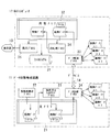
詳しくは図1に示すように、この磁気共鳴イメージング装置は、第1の装置としてのデータ収集再構成装置11と、後述する表示器と共に第2の装置を成すホストコンピュータ12と、このホストコンピュータ12に接続された表示器13と、データ収集再構成装置11及びホストコンピュータ12を相互に接続する、転送手段を成すデータバス14とを備える。
【0018】
また、この磁気共鳴イメージング装置には、図示しないが、静磁場磁石、静磁場電源、傾斜磁場コイル、傾斜磁場電源、RFコイル、送信器、受信器、シーケンサなどのコンポーネントが備えられており、シーケンサからの所望のパルスシーケンス情報に基く指令によってスキャンが実施されるようになっている。このスキャンによって収集されたエコー信号はRFコイルで検出され、受信器に送られる。受信器において、エコー信号は前置増幅、中間周波変換、位相検波、低周波増幅、ローパスフィルタ、及びA/D変換などの処理を経てエコーデータ(生データ)として、上記データ収集再構成装置11に送られる。
【0019】
図1に示すデータ収集再構成装置11は、エコーデータ(生データ)及び画像データを格納する主メモリ21を備え、この主メモリを利用して処理を行うモジュール化された、画像再構成プロセス22、後処理&フィルタリングプロセス23、及びデータ圧縮プロセス24の機能を有する。このプロセス22〜24はCPUが所定のソフトウェアプログラムを実行することで機能的に実現されるが、個々のプロセスの機能に対応したハードウェアに拠るモジュールを装備するようにしてもよい。
【0020】
ホストコンピュータ12は、そのハードウェアとして、ファイルシステム31及び複数のプロセスが利用できる共有メモリ32を備えるとともに、ソフトウェアとしてモジュール化された、データ解凍プロセス33、前処理プロセス34、表示プロセス35、ユーザの要求を受け取るプロセス36を有している。
【0021】
前処理プロセス34は、共有メモリ31に置かれた画像データを簡単な表示のための前処理(表示形式など)である。上記プロセス33〜36はCPUが所定のソフトウェアプログラムを実行することで機能的に実現されるが、個々のプロセスの機能に対応したハードウェアに拠るモジュールを装備するようにしてもよい。
【0022】
なお、ホストコンピュータ12には、スキャンを実施するためのハードウェアが備えられるともに、そのための各種の制御プログラムがインストールされているが、ここでは、それらの記載を割愛している。
【0023】
データ収集再構成装置11及びホストコンピュータ12は相互に、例えばイーサーネット(富士ゼロックス(株)の商標)などのデータバスを介して双方向のデータ転送が可能になっている。このデータ転送速度自体は十分高速の値に設定されている。
【0024】
しかし、以下の理由に因って、十分高速である筈のデータ転送時間が再構成時間を上回ってしまうという律速段階に至ることがある。
【0025】
磁気共鳴イメージングの1つの撮影法として、撮影条件を変化させながら連続的に撮影する連続撮影(フルオロスコピー)が在る。この連続撮影法を実施するには、毎秒十数枚のフレームレートが必要である。このため、収集した生データから画像を得るには高速フーリエ変換(FFT)に拠る再構成を行わなければならないので、データ収集再構成装置11内に生データを再構成する再構成プロセス22(叉は再構成ユニット)を介在させ、データ収集を行いながら再構成可能にしている。再構成における読取り方向はデータ収集と同じであり、再構成時にはデータ収集と同時にデータを読み取ることができるので、2次元画像の最終読取りラインが収集された後の処理時間は、実際には、位相エンコード方向の1次元FFTに要する時間と同等の短時間で済む。つまり、データ収集後、かかる1次元FFTに要する時間が経過すると、2次元画像の再構成も済んでしまうのである。
【0026】
このように、とくに連続撮影を行う場合、再構成時間の見掛け上の短縮によって、十分高速である筈のデータ転送時間が再構成時間よりも長いという事態に陥り、律速段階に至ることがある。
【0027】
そこで、かかる律速段階に至る状況を回避すべく、データ収集再構成装置11には、画像データを圧縮してデータ量を低減するデータ圧縮プロセス24を介在させ、このプロセス24に拠る圧縮画像データをデータバス14を介して転送可能になっている。前述したように、データ圧縮プロセス24はハードウェア要素によって構成してもよい。
【0028】
これに対応して、ホストコンピュータ12には、データ解凍プロセス33が置かれている。このプロセス33により、データバス14を介して転送されてきた、圧縮された画像データが解凍され、この画像データが共有メモリ32に置かれる。前述したように、データ解凍プロセス33はハードウェア要素によって構成してもよい。
【0029】
一方、ホストコンピュータ12のユーザインターフェース36にはユーザから所望の画素値の窓幅と窓レベルが入力される。この窓幅及び窓レベルの情報はユーザインターフェース36から、データバス14による転送手段を介して、データ収集再構成装置11の後処理&フィルタリングプロセス23に渡される。後処理&フィルタリングプロセス23は、この情報で指定された窓幅と窓レベルの画素値の輝度調整を行うようになっている。
【0030】
なお、データ収集再構成装置11及びホストコンピュータ12の主メモリ21及び共有メモリ32には、セマフォなどのアクセスチェック機能を持たせている。これにより、同一メモリ上に置かれた画像データが多プロセスで使用される場合であっても、データの競合が防止され、高速性が確保されている。
【0031】
次いで、本実施形態の全体的な作用効果を説明する。いま、この磁気共鳴イメージング装置は、多重受信コイルを用いた連続撮影(フロオロスコピー)を行うものとする。
【0032】
データ収集再構成装置11において、その主メモリ21に置かれた収集データ(生データ)は、再構成プロセス22を介して上述の如く、収集と殆ど並行して再構成される。この再構成された画像データは後処理&フィルタリングプロセス23により、多重受信コイルであることに対する加算処理が行われ、画素値の窓幅及び窓レベルが指定されて256階調の画像データに生成される。
【0033】
この画像データは更にデータ圧縮プロセス24により、JPEG法などの画像圧縮法に基いて、必要最小限のサイズの画像データに圧縮される。この圧縮された画像データはデータバス14を介してホストコンピュータ12に転送される。
【0034】
ホストコンピュータ12では、データバス14を介して転送されてきた圧縮画像データが解凍されて元のサイズの画像データに復元される。この画像データは共有メモリ32に一時保管される。この保管データはその後、前処理プロセス34により表示形式が整えられ、表示プロセス35により表示器13に表示される。
【0035】
また、画像データを低速のファイルシステムに保存することもできる。この場合、解凍前の画像データをデータ解凍プロセス33から、解凍処理を行わずに保存させる。従って、画像サイズが小さいため、全体の転送性能を低下させることもない。
【0036】
このように本実施形態によれば、データ収集と殆んど並行して再構成が行われ、この再構成後に輝度調整などの必要な処理が施され、この後、この画像データは圧縮されてから、ホストコンピュータに転送される。これに応じて、ホストコンピュータでは、転送されてきた画像データを解凍してから表示処理に付す。このため、連続撮影する場合であって、画像データ処理量が増えた場合でも、システム全体がデータ転送により律速されるという状態を確実に回避できる。従って、データ収集再構成装置からホストコンピュータに画像データを、より高速に渡すことができる。このため、圧縮・解凍に要する時間を転送の短縮時間分よりも短かくなるようにして、単位時間当たりに処理して表示できる画像枚数、即ちフレームレートを向上させることができる。これにより、連続撮影の高速撮影性を低下させることが無い。
【0037】
(第2の実施形態)
図2を参照して、第2の実施形態を説明する。この実施形態は画像圧縮法の別の例に関する。なお、この実施形態及び後述する第3の実施形態において、上述の第1の実施形態と同一叉は同等の構成要素には同一符号を付してその説明を省略叉は簡略化する。
【0038】
図2に示す如く、第2の実施形態に係る磁気共鳴イメージング装置のデータ収集再構成装置11では、画像データの各フレームに対して、その時間方向のフレーム相関を用いた圧縮を行うようになっている。これにより、画像圧縮の効率が良くなる。
【0039】
現在の画像をnとし、これより過去に1,2,3時相だけ遡った画像n−1,n−2,n−3とすれば、それらの画像データのフレーム間相関を画素毎に演算すればよく、この相関画像に基く圧縮画像データがデータバス14を介してホストコンピュータ12に転送される。
【0040】
ホストコンピュータ12でも同様に、解凍された過去の画像を保存しながら、データバス14を介して新しく転送されてきた圧縮画像データとその過去画像とから現在の時相の画像を構成する。
【0041】
一般に、連続撮影(フルオロスコピー)の場合、撮影スライスを一度指定してしまうと、その後から得られる画像の画素値がフレーム毎に変化する部分は画像全体の中で僅かな領域に留まる。このため、現在時相の画像と過去時相の画像との間のフレーム間差分を演算してできる差分画像のデータ量は通常、僅かな値である。つまり、圧縮対象となるデータ量が少なくなるので、データ圧縮の効率も良くなり、転送も高速に行える。この圧縮法には、汎用されているMPEGを初めとして各種の手法を用いることができる。
【0042】
(第3の実施形態)
図3を参照して、第3の実施形態を説明する。この実施形態はパイプライン処理の適用に関する。
【0043】
この実施形態に係る磁気共鳴イメージング装置は、図3に示す如く、そのデータ収集再構成装置11における画像再構成プロセス22、後処理&フィルタリングプロセス23、及びデータ圧縮プロセス24、データバス14、並びに、ホストコンピュータ12におけるデータ解凍プロセス33及び前処理プロセス34において、パイプライン処理が実行されるようになっている。これにより、画像再構成から表示前処理までの一連の処理が並列化され、処理速度が高速化される。このように高速処理された画像は、表示プロセス35により表示器13に順次表示される。
【0044】
従って、第1の実施形態と同様に単位時間当たりの表示画像枚数を多くできるとともに、リソースを有効に活用できる。
【0045】
なお、本発明は上述した各実施形態に記載の構成に限定されるものでは無く、当業者であれば、本発明を、特許請求の範囲に記載された要旨の範囲内で適宜に変更或は変形して実施でき、それらの変更叉は変形に係る構成も本発明に含まれる。
【0046】
【発明の効果】
以上説明したように、本発明に係る磁気共鳴イメージング装置によれば、生データの収集再構成の装置とユーザインターフェース及び表示を担うコンピュータ装置とを分離した構成において、ハードウェア叉はソフトウェアに拠る画像データの圧縮及び解凍を、画像データの転送の前後にてそれぞれ実行することで、律速段階となる画像データ転送の性能を向上させることができ、従って、フルオロスコピー等の高速撮影時の単位時間当たりの表示フレームレートを大幅に向上させることができ、高速撮影の高速性を損なうといった事態を確実に防止できる。
【図面の簡単な説明】
【図1】本発明の第1の実施形態に係る磁気共鳴イメージング装置の概略構成を示す部分ブロック図。
【図2】本発明の第2の実施形態に係る磁気共鳴イメージング装置の概略構成を示す部分ブロック図。
【図3】本発明の第3の実施形態に係る磁気共鳴イメージング装置の概略構成を示す部分ブロック図。
【符号の説明】
11 データ収集再構成装置(第1の装置)
12 ホストコンピュータ(第2の装置)
13 表示器(第2の装置)
14 データバス(転送手段)
21 主メモリ
22 画像再構成プロセス
23 後処理&フィルタリングプロセス
24 データ圧縮プロセス
32 共有メモリ
33 データ解凍プロセス
34 前処理プロセス
35 表示プロセス
36 ユーザインターフェース[0001]
BACKGROUND OF THE INVENTION
The present invention relates to a magnetic resonance imaging (MRI) apparatus that images the inside of a subject, and in particular, a data collection / reconstruction apparatus that collects and reconstructs data (raw data) generated by scanning, and a host computer that displays an image. The present invention relates to a magnetic resonance imaging apparatus of a type in which are separated from each other as separate components, and both are connected via a data bus.
[0002]
[Prior art]
In magnetic resonance imaging, a nuclear spin of a subject placed in a uniform static magnetic field is magnetically excited with a high-frequency signal of its Larmor frequency, and an image is obtained from an MR signal (so-called raw data) generated by this excitation. An imaging method to obtain.
[0003]
Conventionally, in this imaging method, after collecting data by scanning, a method of transferring collected raw data to a host computer without any change has been generally adopted. In this case, the host computer performs all necessary processing from reconstruction of the transferred raw data to filtering, brightness adjustment, and image display. For this reason, there were many cases where high-speed processing could not be supported.
[0004]
One of them is an increase in data volume due to data collection using a plurality of receiving coils. Moreover, since digital processing technology has advanced rapidly and high-speed digital processing is possible, there is a system in which reconstruction means is installed in the data collection system and reconstruction processing is performed while collecting raw data in the data collection system. is made of. As a result, the reconstruction can be completed immediately after the raw data is collected, so that the reconstruction processing time is greatly reduced. Since this reconstructed image data has not yet been subjected to brightness adjustment, it is transferred from the data collection system device to the host computer. In the host computer, brightness adjustment and size conversion are performed on the transferred image data, and the image data is displayed.
[0005]
[Problems to be solved by the invention]
However, in the case of magnetic resonance imaging in which the collected raw data is reconstructed in the data collection system device as described above, although it is possible to cope with an increase in data processing amount by using a plurality of receiving coils, On the other hand, the data transfer for transferring the reconstructed image data to the host computer becomes a rate-determining step for the entire system, and a new problem arises that the number of displayed images per unit time cannot be increased.
[0006]
The present invention was made in order to overcome the current situation faced by the prior art. The data processing amount is increased, and the data transfer system reconfigures the raw data to reconstruct the display frame rate. Even in the case of rate control, the object is to enable image data to be transferred from a data collection system device to a host computer at a high speed and to improve the number of displayed images per unit time.
[0007]
[Means for Solving the Problems]
In order to achieve the above object, according to the magnetic resonance imaging apparatus of the present invention, reconstruction means for reconstructing data collected from a subject along with spin excitation into an image, and the reconstructed image data A first apparatus having post-processing means for predetermined post-processing; display pre-processing means for subjecting the reconstructed image data to display pre-processing; and display means for displaying the pre-display processed image data And a transfer means for transferring data between the first and second devices. Further, the first apparatus includes a compression unit that compresses the image data post-processed by the post-processing unit and passes the compressed image data to the transfer unit, and the post-processing unit is sent via the transfer unit. The second device is configured to adjust the luminance according to the window value and window level information of the pixel value, and the second device generates the window width and window level information of the pixel value and transfers the information to the transfer unit. and means for transferring to the first device via, characterized in that a decompression means to pass to the display preprocessing means compressed image data that has been transferred to decompress via the transfer means.
[0008]
As a result, the image data reconstructed by the first device is subjected to necessary processing and then compressed, and then transferred to the second device. In response to this, in the second apparatus, the transferred image data is decompressed and thereafter subjected to display processing. For this reason, even in the case of continuous shooting, even when the amount of image data processing increases, it is possible to reliably avoid the state where the entire system is rate-limited by data transfer, and the number of images that can be processed and displayed per unit time, That is, the frame rate can be improved.
[0009]
Preferably, the post-processing means is means for performing predetermined filtering and brightness adjustment on the reconstructed image data. The collected data is, for example, raw data collected by performing fluoroscopy (continuous shooting).
[0011]
Further, in each configuration described above, the compression unit may be a unit that performs image compression based on a correlation of the data in the frame time axis direction.
[0012]
Further, as an example, each of the reconstruction unit, the post-processing unit, the compression unit, the transfer unit, the decompression unit, and the display pre-processing unit may be configured as a unit driven by pipeline processing.
[0014]
DETAILED DESCRIPTION OF THE INVENTION
Embodiments of the present invention will be described below with reference to the accompanying drawings.
[0015]
(First embodiment)
A magnetic resonance imaging apparatus according to the first embodiment will be described with reference to FIG.
[0016]
This magnetic resonance imaging apparatus collects and reconstructs MR data (raw data) generated along with scanning, and is a so-called data collection system apparatus (data collection apparatus, data collection reconstruction apparatus, data processing apparatus, etc.) Is often separated from the host computer responsible for various functions including the interface function and image display function associated with the user's interaction, and the image data collected and reconstructed by the data collection system device is hosted. It is configured to transfer to a computer.
[0017]
Specifically, as shown in FIG. 1, the magnetic resonance imaging apparatus includes a data collection / reconstruction apparatus 11 as a first apparatus, a host computer 12 that forms a second apparatus together with a display unit to be described later, and the host computer 12 And a
[0018]
Although not shown, this magnetic resonance imaging apparatus includes components such as a static magnetic field magnet, a static magnetic field power supply, a gradient magnetic field coil, a gradient magnetic field power supply, an RF coil, a transmitter, a receiver, and a sequencer. The scanning is performed by a command based on the desired pulse sequence information. The echo signal collected by this scan is detected by the RF coil and sent to the receiver. In the receiver, the echo signal is processed as pre-amplification, intermediate frequency conversion, phase detection, low-frequency amplification, low-pass filter, A / D conversion, and the like as echo data (raw data), and the data collection reconstruction apparatus 11 Sent to.
[0019]
A data collection / reconstruction apparatus 11 shown in FIG. 1 includes a
[0020]
The host computer 12 includes, as hardware, a
[0021]
The
[0022]
The host computer 12 is provided with hardware for performing scanning, and various control programs for the hardware are installed, but the description thereof is omitted here.
[0023]
The data collection / reconstruction device 11 and the host computer 12 can bidirectionally transfer data to each other via a data bus such as Ethernet (trademark of Fuji Xerox Co., Ltd.). This data transfer rate itself is set to a sufficiently high value.
[0024]
However, due to the following reasons, the data transfer time, which is sufficiently fast, may reach the rate-determining stage, which exceeds the reconstruction time.
[0025]
As one imaging method of magnetic resonance imaging, there is continuous imaging (fluoroscopy) in which imaging is continuously performed while changing imaging conditions. In order to carry out this continuous photographing method, a frame rate of 10 or more frames per second is required. For this reason, in order to obtain an image from the collected raw data, reconstruction based on Fast Fourier Transform (FFT) must be performed. Therefore, a reconstruction process 22 (fork) that reconstructs the raw data in the data collection reconstruction device 11. Can be reconfigured while collecting data. Since the reading direction in reconstruction is the same as in data collection, and data can be read simultaneously with data collection during reconstruction, the processing time after the last read line of the two-dimensional image is collected is actually a phase. A short time equivalent to the time required for the one-dimensional FFT in the encoding direction is sufficient. That is, when the time required for such a one-dimensional FFT elapses after data collection, the reconstruction of the two-dimensional image is completed.
[0026]
In this way, particularly when continuous shooting is performed, due to the apparent shortening of the reconstruction time, the data transfer time, which is sufficiently high, may be longer than the reconstruction time, and the rate-limiting step may be reached.
[0027]
Therefore, in order to avoid such a situation that reaches the rate-determining step, the data collection / reconstruction apparatus 11 is provided with a
[0028]
Correspondingly, a
[0029]
On the other hand, the window width and window level of a desired pixel value are input from the user to the
[0030]
The
[0031]
Next, the overall function and effect of this embodiment will be described. Now, it is assumed that this magnetic resonance imaging apparatus performs continuous imaging (fluoroscopic copying) using multiple receiving coils.
[0032]
In the data collection / reconstruction apparatus 11, the collected data (raw data) placed in the
[0033]
This image data is further compressed by the
[0034]
In the host computer 12, the compressed image data transferred via the
[0035]
In addition, image data can be stored in a low-speed file system. In this case, the image data before decompression is stored from the
[0036]
As described above, according to the present embodiment, reconstruction is performed almost in parallel with data collection, and necessary processing such as brightness adjustment is performed after the reconstruction, and thereafter, the image data is compressed. To the host computer. In response to this, the host computer decompresses the transferred image data and applies it to display processing. For this reason, even in the case of continuous shooting, even when the amount of image data processing increases, it is possible to reliably avoid the state where the entire system is rate-limited by data transfer. Therefore, the image data can be transferred from the data collection / reconstruction device to the host computer at a higher speed. Therefore, it is possible to improve the number of images that can be processed and displayed per unit time, that is, the frame rate, so that the time required for compression / decompression is shorter than the shortened transfer time. As a result, the high-speed shooting performance of continuous shooting is not deteriorated.
[0037]
(Second Embodiment)
A second embodiment will be described with reference to FIG. This embodiment relates to another example of an image compression method. In this embodiment and a third embodiment to be described later, the same reference numerals are given to the same or equivalent components as those in the first embodiment, and the description thereof will be omitted or simplified.
[0038]
As shown in FIG. 2, the data acquisition / reconstruction apparatus 11 of the magnetic resonance imaging apparatus according to the second embodiment performs compression using the frame correlation in the time direction for each frame of the image data. ing. Thereby, the efficiency of image compression is improved.
[0039]
Assuming that the current image is n and the images n-1, n-2, and n-3 that are traced back by 1, 2, and 3 time phases in the past, the inter-frame correlation of these image data is calculated for each pixel. The compressed image data based on the correlation image is transferred to the host computer 12 via the
[0040]
Similarly, the host computer 12 forms an image of the current time phase from the compressed image data newly transferred via the
[0041]
In general, in the case of continuous shooting (fluoroscopy), once a shooting slice is designated, a portion where the pixel value of an image obtained thereafter changes for each frame remains in a small area in the entire image. For this reason, the data amount of the difference image that can be obtained by calculating the inter-frame difference between the current time phase image and the past time phase image is usually a small value. That is, since the amount of data to be compressed is reduced, the efficiency of data compression is improved and the transfer can be performed at high speed. For this compression method, various methods including MPEG which is widely used can be used.
[0042]
(Third embodiment)
The third embodiment will be described with reference to FIG. This embodiment relates to the application of pipeline processing.
[0043]
As shown in FIG. 3, the magnetic resonance imaging apparatus according to this embodiment includes an
[0044]
Therefore, the number of display images per unit time can be increased as in the first embodiment, and resources can be used effectively.
[0045]
It should be noted that the present invention is not limited to the configurations described in the above-described embodiments, and those skilled in the art will appropriately modify or modify the present invention within the scope of the gist described in the claims. The present invention can be implemented with modifications, and configurations related to these modifications or modifications are also included in the present invention.
[0046]
【The invention's effect】
As described above, according to the magnetic resonance imaging apparatus according to the present invention, in a configuration in which a raw data collection / reconstruction apparatus and a user interface and a computer apparatus responsible for display are separated, an image based on hardware or software By performing data compression and decompression before and after image data transfer, the performance of image data transfer at the rate-determining stage can be improved. Therefore, per unit time during high-speed shooting such as fluoroscopy. The display frame rate can be greatly improved, and it is possible to reliably prevent a situation in which the high-speed shooting performance is impaired.
[Brief description of the drawings]
FIG. 1 is a partial block diagram showing a schematic configuration of a magnetic resonance imaging apparatus according to a first embodiment of the present invention.
FIG. 2 is a partial block diagram showing a schematic configuration of a magnetic resonance imaging apparatus according to a second embodiment of the present invention.
FIG. 3 is a partial block diagram showing a schematic configuration of a magnetic resonance imaging apparatus according to a third embodiment of the present invention.
[Explanation of symbols]
11 Data collection and reconstruction device (first device)
12 Host computer (second device)
13 Display (second device)
14 Data bus (transfer means)
21
Claims (5)
この再構成された画像データを表示前処理に付す表示前処理手段と、この表示前処理された画像データを表示する表示手段とを有する第2の装置と、
前記第1及び第2の装置の間でデータ転送を担う転送手段とを備えた磁気共鳴イメージング装置において、
前記第1の装置は、前記後処理手段により後処理された画像データを圧縮して前記転送手段に渡す圧縮手段を備えるとともに、前記後処理手段は、前記転送手段を介して送られてきた画素値の窓幅と窓レベルの情報に応じて輝度調整を行う手段であり、
前記第2の装置は、前記画素値の窓幅と窓レベルの情報を発生させるとともに当該情報を前記転送手段を介して前記第1の装置に転送させる手段と、前記転送手段を介して転送されてきた圧縮画像データを解凍して前記表示前処理手段に渡す解凍手段とを備えた、ことを特徴とする磁気共鳴イメージング装置。A first apparatus having reconstruction means for reconstructing data collected from a subject with spin excitation into an image, and post-processing means for subjecting the reconstructed image data to predetermined post-processing;
A second device having display preprocessing means for subjecting the reconstructed image data to display preprocessing, and display means for displaying the preprocessed image data;
A magnetic resonance imaging apparatus comprising transfer means for transferring data between the first and second apparatuses;
The first apparatus includes a compression unit that compresses the image data post-processed by the post-processing unit and passes the compressed image data to the transfer unit, and the post-processing unit includes a pixel sent via the transfer unit. It is a means to adjust the brightness according to the value window width and window level information,
The second device generates window width and window level information of the pixel value and transfers the information to the first device via the transfer unit, and is transferred via the transfer unit. and a decompression means to pass to the display preprocessing means compressed image data has been decompress, magnetic resonance imaging apparatus characterized by.
前記後処理手段は、前記再構成された画像データに対して所定のフィルタリング及び輝度調整を行う手段である磁気共鳴イメージング装置。The magnetic resonance imaging apparatus according to claim 1.
The magnetic resonance imaging apparatus, wherein the post-processing means is means for performing predetermined filtering and brightness adjustment on the reconstructed image data.
前記収集データは、フルオロスコピー(連続撮影)を行って収集した生データである磁気共鳴イメージング装置。The magnetic resonance imaging apparatus according to claim 1 or 2,
The magnetic resonance imaging apparatus, wherein the collected data is raw data collected by performing fluoroscopy (continuous imaging).
前記圧縮手段は、前記データのフレーム時間軸方向の相関に基く画像圧縮を行う手段である磁気共鳴イメージング装置。The magnetic resonance imaging apparatus according to any one of claims 1 to 3 ,
The magnetic resonance imaging apparatus, wherein the compression unit is a unit that performs image compression based on a correlation of the data in the frame time axis direction.
前記再構成手段、前記後処理手段、前記圧縮手段、前記転送手段、前記解凍手段、及び前記表示前処理手段のそれぞれはパイプライン処理で駆動する手段である磁気共鳴イメージング装置。The magnetic resonance imaging apparatus according to any one of claims 1 to 4 ,
Each of the reconstruction means, the post-processing means, the compression means, the transfer means, the decompression means, and the display pre-processing means is a magnetic resonance imaging apparatus that is driven by pipeline processing.
Priority Applications (1)
| Application Number | Priority Date | Filing Date | Title |
|---|---|---|---|
| JP2000224151A JP4434447B2 (en) | 2000-07-25 | 2000-07-25 | Magnetic resonance imaging system |
Applications Claiming Priority (1)
| Application Number | Priority Date | Filing Date | Title |
|---|---|---|---|
| JP2000224151A JP4434447B2 (en) | 2000-07-25 | 2000-07-25 | Magnetic resonance imaging system |
Publications (3)
| Publication Number | Publication Date |
|---|---|
| JP2002034950A JP2002034950A (en) | 2002-02-05 |
| JP2002034950A5 JP2002034950A5 (en) | 2007-09-06 |
| JP4434447B2 true JP4434447B2 (en) | 2010-03-17 |
Family
ID=18718160
Family Applications (1)
| Application Number | Title | Priority Date | Filing Date |
|---|---|---|---|
| JP2000224151A Expired - Fee Related JP4434447B2 (en) | 2000-07-25 | 2000-07-25 | Magnetic resonance imaging system |
Country Status (1)
| Country | Link |
|---|---|
| JP (1) | JP4434447B2 (en) |
Families Citing this family (3)
| Publication number | Priority date | Publication date | Assignee | Title |
|---|---|---|---|---|
| JP5038617B2 (en) * | 2005-11-15 | 2012-10-03 | 株式会社東芝 | Magnetic resonance imaging system |
| US7663364B2 (en) | 2007-02-06 | 2010-02-16 | Kabushiki Kaisha Toshiba | Magnetic resonance imaging apparatus, image processing apparatus, computer program product, and data storing method |
| JP5306413B2 (en) * | 2011-05-25 | 2013-10-02 | 株式会社東芝 | Magnetic resonance imaging system |
-
2000
- 2000-07-25 JP JP2000224151A patent/JP4434447B2/en not_active Expired - Fee Related
Also Published As
| Publication number | Publication date |
|---|---|
| JP2002034950A (en) | 2002-02-05 |
Similar Documents
| Publication | Publication Date | Title |
|---|---|---|
| US6320380B1 (en) | MRI method and apparatus for increasing the efficiency of echo lanar imaging and other late echo techniques | |
| CN104781685A (en) | Image reconstruction for dynamic MRI with incoherent sampling and redundant HAAR wavelets | |
| CN108776318B (en) | Magnetic resonance multi-contrast image reconstruction | |
| JPH1176201A (en) | Method for correcting maxwell term errors | |
| KR100452645B1 (en) | Image processing method and apparatus, recording medium, and imaging apparatus | |
| CN111856367B (en) | Magnetic resonance imaging system and method for detecting and correcting patient motion | |
| US8155476B2 (en) | Image processing apparatus, image processing method, and program | |
| US20080112650A1 (en) | Image Processor, Image Processing Method, and Program | |
| US11016154B2 (en) | Magnetic resonance imaging apparatus and image reconstruction program | |
| JP2008253733A (en) | Mri device and control method therefor | |
| JP4434447B2 (en) | Magnetic resonance imaging system | |
| EP1139113A3 (en) | Combination of fluid complex images acquired using magnetic resonance imaging | |
| US8879809B2 (en) | Method to process medical image data | |
| JPH0723926A (en) | Image quality improving method for dynamic image | |
| CN113558600A (en) | Magnetic resonance imaging apparatus and image processing method | |
| JPH1156811A (en) | Image correcting method | |
| JP4960575B2 (en) | Automatic imaging area optimization to maximize resolution and eliminate aliasing artifacts | |
| JP2009508557A (en) | Magnetic resonance imaging with multiple types of contrast | |
| EP1176555A2 (en) | Image processing method and apparatus, recording medium, and imaging apparatus | |
| JP2808782B2 (en) | MR device | |
| US20240331109A1 (en) | Medical image processing apparatus, magnetic resonance imaging apparatus, and medical image processing method | |
| US7388917B2 (en) | Image-processing method and image processor | |
| US20240331116A1 (en) | Medical image processing apparatus, magnetic resonance imaging apparatus, and medical image processing method | |
| JP2008212625A (en) | Magnetic resonance imaging apparatus, image processing apparatus, computer program product, and data storing method | |
| CN114325523B (en) | T1 value determining method, device, electronic equipment and storage medium |
Legal Events
| Date | Code | Title | Description |
|---|---|---|---|
| A521 | Request for written amendment filed |
Free format text: JAPANESE INTERMEDIATE CODE: A523 Effective date: 20070720 |
|
| A621 | Written request for application examination |
Free format text: JAPANESE INTERMEDIATE CODE: A621 Effective date: 20070720 |
|
| A977 | Report on retrieval |
Free format text: JAPANESE INTERMEDIATE CODE: A971007 Effective date: 20090717 |
|
| A131 | Notification of reasons for refusal |
Free format text: JAPANESE INTERMEDIATE CODE: A131 Effective date: 20090728 |
|
| A521 | Request for written amendment filed |
Free format text: JAPANESE INTERMEDIATE CODE: A523 Effective date: 20090917 |
|
| TRDD | Decision of grant or rejection written | ||
| A01 | Written decision to grant a patent or to grant a registration (utility model) |
Free format text: JAPANESE INTERMEDIATE CODE: A01 Effective date: 20091201 |
|
| A01 | Written decision to grant a patent or to grant a registration (utility model) |
Free format text: JAPANESE INTERMEDIATE CODE: A01 |
|
| A61 | First payment of annual fees (during grant procedure) |
Free format text: JAPANESE INTERMEDIATE CODE: A61 Effective date: 20091222 |
|
| R151 | Written notification of patent or utility model registration |
Ref document number: 4434447 Country of ref document: JP Free format text: JAPANESE INTERMEDIATE CODE: R151 |
|
| FPAY | Renewal fee payment (event date is renewal date of database) |
Free format text: PAYMENT UNTIL: 20130108 Year of fee payment: 3 |
|
| FPAY | Renewal fee payment (event date is renewal date of database) |
Free format text: PAYMENT UNTIL: 20140108 Year of fee payment: 4 |
|
| S111 | Request for change of ownership or part of ownership |
Free format text: JAPANESE INTERMEDIATE CODE: R313117 Free format text: JAPANESE INTERMEDIATE CODE: R313114 Free format text: JAPANESE INTERMEDIATE CODE: R313111 |
|
| R371 | Transfer withdrawn |
Free format text: JAPANESE INTERMEDIATE CODE: R371 |
|
| S111 | Request for change of ownership or part of ownership |
Free format text: JAPANESE INTERMEDIATE CODE: R313114 Free format text: JAPANESE INTERMEDIATE CODE: R313117 Free format text: JAPANESE INTERMEDIATE CODE: R313111 |
|
| R350 | Written notification of registration of transfer |
Free format text: JAPANESE INTERMEDIATE CODE: R350 |
|
| S533 | Written request for registration of change of name |
Free format text: JAPANESE INTERMEDIATE CODE: R313533 |
|
| R350 | Written notification of registration of transfer |
Free format text: JAPANESE INTERMEDIATE CODE: R350 |
|
| LAPS | Cancellation because of no payment of annual fees |