JP4432809B2 - Rotation angle detector - Google Patents
Rotation angle detector Download PDFInfo
- Publication number
- JP4432809B2 JP4432809B2 JP2005076812A JP2005076812A JP4432809B2 JP 4432809 B2 JP4432809 B2 JP 4432809B2 JP 2005076812 A JP2005076812 A JP 2005076812A JP 2005076812 A JP2005076812 A JP 2005076812A JP 4432809 B2 JP4432809 B2 JP 4432809B2
- Authority
- JP
- Japan
- Prior art keywords
- detection
- rotation angle
- rotating body
- spur gear
- rotation
- Prior art date
- Legal status (The legal status is an assumption and is not a legal conclusion. Google has not performed a legal analysis and makes no representation as to the accuracy of the status listed.)
- Expired - Fee Related
Links
Images


Classifications
-
- B—PERFORMING OPERATIONS; TRANSPORTING
- B62—LAND VEHICLES FOR TRAVELLING OTHERWISE THAN ON RAILS
- B62D—MOTOR VEHICLES; TRAILERS
- B62D15/00—Steering not otherwise provided for
- B62D15/02—Steering position indicators ; Steering position determination; Steering aids
- B62D15/021—Determination of steering angle
- B62D15/0215—Determination of steering angle by measuring on the steering column
-
- G—PHYSICS
- G01—MEASURING; TESTING
- G01D—MEASURING NOT SPECIALLY ADAPTED FOR A SPECIFIC VARIABLE; ARRANGEMENTS FOR MEASURING TWO OR MORE VARIABLES NOT COVERED IN A SINGLE OTHER SUBCLASS; TARIFF METERING APPARATUS; MEASURING OR TESTING NOT OTHERWISE PROVIDED FOR
- G01D5/00—Mechanical means for transferring the output of a sensing member; Means for converting the output of a sensing member to another variable where the form or nature of the sensing member does not constrain the means for converting; Transducers not specially adapted for a specific variable
- G01D5/12—Mechanical means for transferring the output of a sensing member; Means for converting the output of a sensing member to another variable where the form or nature of the sensing member does not constrain the means for converting; Transducers not specially adapted for a specific variable using electric or magnetic means
- G01D5/14—Mechanical means for transferring the output of a sensing member; Means for converting the output of a sensing member to another variable where the form or nature of the sensing member does not constrain the means for converting; Transducers not specially adapted for a specific variable using electric or magnetic means influencing the magnitude of a current or voltage
- G01D5/142—Mechanical means for transferring the output of a sensing member; Means for converting the output of a sensing member to another variable where the form or nature of the sensing member does not constrain the means for converting; Transducers not specially adapted for a specific variable using electric or magnetic means influencing the magnitude of a current or voltage using Hall-effect devices
- G01D5/145—Mechanical means for transferring the output of a sensing member; Means for converting the output of a sensing member to another variable where the form or nature of the sensing member does not constrain the means for converting; Transducers not specially adapted for a specific variable using electric or magnetic means influencing the magnitude of a current or voltage using Hall-effect devices influenced by the relative movement between the Hall device and magnetic fields
-
- G—PHYSICS
- G01—MEASURING; TESTING
- G01D—MEASURING NOT SPECIALLY ADAPTED FOR A SPECIFIC VARIABLE; ARRANGEMENTS FOR MEASURING TWO OR MORE VARIABLES NOT COVERED IN A SINGLE OTHER SUBCLASS; TARIFF METERING APPARATUS; MEASURING OR TESTING NOT OTHERWISE PROVIDED FOR
- G01D5/00—Mechanical means for transferring the output of a sensing member; Means for converting the output of a sensing member to another variable where the form or nature of the sensing member does not constrain the means for converting; Transducers not specially adapted for a specific variable
- G01D5/12—Mechanical means for transferring the output of a sensing member; Means for converting the output of a sensing member to another variable where the form or nature of the sensing member does not constrain the means for converting; Transducers not specially adapted for a specific variable using electric or magnetic means
- G01D5/244—Mechanical means for transferring the output of a sensing member; Means for converting the output of a sensing member to another variable where the form or nature of the sensing member does not constrain the means for converting; Transducers not specially adapted for a specific variable using electric or magnetic means influencing characteristics of pulses or pulse trains; generating pulses or pulse trains
- G01D5/245—Mechanical means for transferring the output of a sensing member; Means for converting the output of a sensing member to another variable where the form or nature of the sensing member does not constrain the means for converting; Transducers not specially adapted for a specific variable using electric or magnetic means influencing characteristics of pulses or pulse trains; generating pulses or pulse trains using a variable number of pulses in a train
- G01D5/2451—Incremental encoders
-
- G—PHYSICS
- G01—MEASURING; TESTING
- G01D—MEASURING NOT SPECIALLY ADAPTED FOR A SPECIFIC VARIABLE; ARRANGEMENTS FOR MEASURING TWO OR MORE VARIABLES NOT COVERED IN A SINGLE OTHER SUBCLASS; TARIFF METERING APPARATUS; MEASURING OR TESTING NOT OTHERWISE PROVIDED FOR
- G01D2205/00—Indexing scheme relating to details of means for transferring or converting the output of a sensing member
- G01D2205/20—Detecting rotary movement
- G01D2205/26—Details of encoders or position sensors specially adapted to detect rotation beyond a full turn of 360°, e.g. multi-rotation
Description
本発明は、主に自動車のステアリングの回転角度検出等に用いられる回転角度検出装置に関するものである。 The present invention relates to a rotation angle detection device mainly used for detecting a rotation angle of a steering wheel of an automobile.
近年、自動車の高機能化が進む中、各種制御のため様々な回転角度検出装置を用いてステアリングの回転角度を検出するものが増えている。 In recent years, as the functions of automobiles have advanced, the number of steering angle detection devices using various rotation angle detection devices for various controls has increased.
このような従来の回転角度検出装置について、図4を用いて説明する。 Such a conventional rotation angle detection device will be described with reference to FIG.
図4は従来の回転角度検出装置の分解斜視図であり、同図において、1は外周に平歯車部1Aが形成された回転体で、中央部には挿通するステアリング(図示せず)の軸と係合する係合部1Bが設けられると共に、下面には略円筒状の摺接部1Cが形成されている。
FIG. 4 is an exploded perspective view of a conventional rotation angle detecting device. In FIG. 4, reference numeral 1 denotes a rotating body having a spur gear portion 1A formed on the outer periphery, and a shaft of a steering (not shown) inserted through the center portion. An engaging portion 1B that engages with the slidable portion is provided, and a substantially cylindrical sliding
そして、2は略箱型の絶縁樹脂製のケースで、底面には回転体1の摺接部1Cよりやや大きく、上方へ円筒状に突出した貫通孔2Aが形成され、この貫通孔2A内に摺接部1Cが挿通されて、回転体1がケース2に回転可能に装着されている。
Reference numeral 2 denotes a substantially box-shaped case made of an insulating resin. A through
また、3はケース2底面に回転可能に装着された第一の検出体で、この外周の平歯車部3Aが回転体1の平歯車部1Aに噛合すると共に、この第一の検出体3の中央には、磁石4がインサート成形等により装着されている。
さらに、5はケース2底面に回転可能に装着された第二の検出体で、外周には第一の検出体3の平歯車部3Aとは歯数の異なる平歯車部5Aが設けられ、この平歯車部5Aが平歯車部3Aに噛合すると共に、第二の検出体5の中央には、磁石6が装着されている。
Further, 5 is a second detector rotatably mounted on the bottom surface of the case 2, and a
そして、7は第一の検出体3及び第二の検出体5の上方にほぼ平行に配置された配線基板で、両面に複数の配線パターン(図示せず)が形成されると共に、第一の検出体3の磁石4との対向面には磁気検出素子8が、第二の検出体5の磁石6との対向面には磁気検出素子9が各々装着されている。
また、このように磁石4とこれに対向した磁気検出素子8、及び磁石6とこれに対向した磁気検出素子9によって、検出手段が各々形成されると共に、配線基板7にはマイコン等の電子部品によって、磁気検出素子8、9に接続された制御手段10が形成されて、回転角度検出装置が構成されている。
The magnet 4 and the magnetic detection element 8 opposed to the magnet 4 and the
そして、このような回転角度検出装置は、制御手段10がコネクタ(図示せず)等を通して自動車本体の電子回路(図示せず)に接続されると共に、回転体1の係合部1Bにはステアリングの軸が挿通されて、自動車に装着される。 In such a rotation angle detection device, the control means 10 is connected to an electronic circuit (not shown) of the automobile body through a connector (not shown) or the like, and the engaging portion 1B of the rotating body 1 has a steering wheel. The shaft is inserted and attached to the automobile.
以上の構成において、運転時にステアリングを回転すると、回転体1が回転し、これに連動して第一及び第二の検出体3と5が回転するため、これらの中央に装着された磁石4と6も回転して、この磁石4と6の変化する磁力を磁気検出素子8と9が検出し、これらの検出信号が制御手段10へ出力される。
In the above configuration, when the steering wheel is rotated during driving, the rotating body 1 rotates, and the first and
なお、この時、第一及び第二の検出体3と5は、平歯車部3Aと5Aの歯数が異なり回転速度が異なるため、各々の検出手段からの検出信号は、周期や位相の異なる検出信号となる。
At this time, since the first and
そして、このような二つの異なる検出信号と各々の歯数から、制御手段10が所定の演算を行って、回転体1即ちステアリングの回転角度を検出し、これが自動車本体の電子回路へ出力されて、様々な制御が行われるように構成されているものであった。 Then, from such two different detection signals and the respective number of teeth, the control means 10 performs a predetermined calculation to detect the rotation angle of the rotating body 1, that is, the steering, which is output to the electronic circuit of the automobile body. In this configuration, various controls are performed.
なお、この出願の発明に関連する先行技術文献情報としては、例えば、特許文献1が知られている。
しかしながら、上記従来の回転角度検出装置においては、摺接部1Cがやや大きな径の貫通孔2A内に挿通されて、回転体1がケース2に回転可能に装着されているため、この摺接部1Cと貫通孔2Aとの隙間によって、回転体1の回転に偏心が発生し、第二の検出体5の回転に誤差が生じて、回転角度の高精度な検出が困難であるという課題があった。
However, in the conventional rotation angle detecting device, the sliding
本発明は、このような従来の課題を解決するものであり、簡易な構成で、高精度な回転角度の検出が可能な回転角度検出装置を提供することを目的とする。 The present invention solves such a conventional problem, and an object of the present invention is to provide a rotation angle detection device capable of detecting a rotation angle with high accuracy with a simple configuration.
上記目的を達成するために本発明は、以下の構成を有するものである。 In order to achieve the above object, the present invention has the following configuration.
本発明の請求項1に記載の発明は、回転体またはこれに連動して回転する検出体の一方を、他方へ押圧する付勢手段を設けると共に、ケースの貫通孔に、挿通され押圧付勢された回転体の摺接部が常に当接する複数の突出部を形成したものであり、回転体または検出体を押圧付勢し、回転体の摺接部をケースの貫通孔の突出部に弾接させて、回転体を回転させることによって、回転体の偏心を防ぎ、誤差がなく、高精度な回転角度の検出が可能な回転角度検出装置を得ることができるという作用を有する。 According to the first aspect of the present invention, there is provided an urging means for pressing one of the rotating body or the detecting body rotating in conjunction with the rotating body to the other, and the pressure urging is inserted into the through hole of the case . The slidable contact portion of the rotating body is formed with a plurality of protruding portions that are always in contact with each other. The rotating body or the detection body is pressed and urged, and the slidable contact portion of the rotating body is elastically projected to the protruding portion of the through hole of the case. By rotating the rotating body in contact with the rotating body, the rotating body can be prevented from being decentered, and there can be obtained a rotation angle detecting device capable of detecting the rotation angle with high accuracy and without error.
請求項2に記載の発明は、請求項1記載の発明において、複数の突出部を、付勢手段の押圧方向と対称位置に等間隔で形成したものであり、付勢力に対して回転体をバランスよく保持し、回転体の偏心を確実に防止することができるという作用を有する。 The invention according to claim 2 is the invention according to claim 1, wherein the plurality of protrusions are formed at equal intervals in a symmetrical position with respect to the pressing direction of the urging means, and the rotating body is provided against the urging force. It has the effect | action that it maintains with balance and can prevent eccentricity of a rotary body reliably.
以上のように本発明によれば、簡易な構成で、高精度な回転角度の検出が可能な回転角度検出装置を実現できるという有利な効果が得られる。 As described above, according to the present invention, it is possible to obtain an advantageous effect that a rotation angle detection device capable of detecting a rotation angle with high accuracy can be realized with a simple configuration.
以下、本発明の一実施の形態について、図1〜図3を用いて説明する。 Hereinafter, an embodiment of the present invention will be described with reference to FIGS.
なお、背景技術の項で説明した構成と同一構成の部分には同一符号を付して、詳細な説明を簡略化する。 In addition, the same code | symbol is attached | subjected to the part of the structure same as the structure demonstrated in the term of background art, and detailed description is simplified.
(実施の形態)
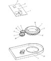
図1は本発明の一実施の形態による回転角度検出装置の平面図、図2は同分解斜視図であり、同図において、1は外周に平歯車部1Aが形成された絶縁樹脂または金属製の回転体で、中央部には挿通するステアリング(図示せず)の軸と係合する係合部1Bが設けられると共に、下面には略円筒状の摺接部1Cが形成されている。
(Embodiment)
FIG. 1 is a plan view of a rotation angle detection device according to an embodiment of the present invention, FIG. 2 is an exploded perspective view thereof, and in FIG. 1, reference numeral 1 denotes an insulating resin or metal having a spur gear portion 1A formed on the outer periphery. An engaging portion 1B that engages with a shaft of a steering (not shown) that is inserted is provided at the center portion, and a substantially cylindrical sliding
そして、12は略箱型で絶縁樹脂製のケースで、底面には回転体1の摺接部1Cよりやや大きく、上方へ円筒状に突出した貫通孔12Aが形成され、この貫通孔12A内に摺接部1Cが挿通されて、回転体1がケース12に回転可能に装着されている。
A substantially box-shaped case made of an
また、3はケース12底面に回転可能に装着された絶縁樹脂または金属製の第一の検出体で、この外周の平歯車部3Aが回転体1の平歯車部1Aに噛合すると共に、この第一の検出体3の中央には、磁石4がインサート成形等により装着されている。
さらに、5はケース12底面に回転可能に装着された第二の検出体で、外周には第一の検出体3の平歯車部3Aとは歯数の異なる平歯車部5Aが設けられ、この平歯車部5Aが平歯車部3Aに噛合すると共に、第二の検出体5の中央には、磁石6が装着されている。
Further, 5 is a second detector rotatably mounted on the bottom surface of the
そして、7は第一の検出体3及び第二の検出体5の上方にほぼ平行に配置された配線基板で、両面に複数の配線パターン(図示せず)が形成されると共に、第一の検出体3の磁石4との対向面には磁気検出素子8が、第二の検出体5の磁石6との対向面には磁気検出素子9が各々装着されている。
また、このように磁石4とこれに対向した磁気検出素子8、及び磁石6とこれに対向した磁気検出素子9によって、第一及び第二の検出手段13と14が各々形成されると共に、配線基板7にはマイコン等の電子部品によって、磁気検出素子8、9に接続された制御手段10が形成されている。
In addition, the magnet 4 and the magnetic detection element 8 opposed to the magnet 4, and the
さらに、15は付勢手段としての鋼または銅合金製のばねで、やや撓んだ状態で一端がケース12底面に保持されると共に、他端が第一の検出体3に弾接して、第一の検出体3を回転体1方向へ押圧している。
Furthermore, 15 is a spring made of steel or copper alloy as an urging means. One end is held on the bottom surface of the
また、回転体1の摺接部1Cが挿通されたケース12の貫通孔12A内には、複数の突出部12Bが、ばね15による第一の検出体3の回転体1への押圧方向とは対称位置に等間隔で、つまり、第一の検出体3とは逆側の内周壁に、押圧方向と複数の突出部12Bが各々120度の間隔になるように形成され、この複数の突出部12Bに第一の検出体3に押圧された回転体1の摺接部1Cが弾接して、回転角度検出装置が構成されている。
In addition, in the
そして、このような回転角度検出装置は、制御手段10がコネクタ(図示せず)等を通して自動車本体の電子回路(図示せず)に接続されると共に、回転体1の係合部1Bにはステアリングの軸が挿通されて、自動車に装着される。 In such a rotation angle detection device, the control means 10 is connected to an electronic circuit (not shown) of the automobile body through a connector (not shown) or the like, and the engaging portion 1B of the rotating body 1 has a steering wheel. The shaft is inserted and attached to the automobile.
以上の構成において、運転時にステアリングを回転すると、これに係合した回転体1が回転し、この外周の平歯車部1Aに平歯車部3Aが噛合した第一の検出体3、及び平歯車部3Aに平歯車部5Aが噛合した第二の検出体5が連動して回転する。
In the above configuration, when the steering is rotated during operation, the rotating body 1 engaged with the steering rotates, and the
そして、第一及び第二の検出体3と5の中央に装着された磁石4と6も回転し、この磁石4と6の変化する磁力を磁気検出素子8と9が正弦波や余弦波の電圧波形からなる検出信号として各々検出して、漸次増加減少する鋸歯状波形の検出信号が制御手段10へ出力される。
Then, the
なお、この時、第一及び第二の検出体3と5は、平歯車部3Aと5Aの歯数が異なり回転速度が異なるため、第一及び第二の検出手段13と14からの検出信号は、周期や位相が異なる検出信号となる。
At this time, since the first and
そして、このような二つの異なる検出信号と、回転体1や第一及び第二の検出体3、5の各々の歯数から、制御手段10が所定の演算を行って、回転体1即ちステアリングの回転角度を検出し、これが自動車本体の電子回路へ出力されて、車両の様々な制御が行われる。
Then, the control means 10 performs a predetermined calculation from the two different detection signals and the number of teeth of each of the rotating body 1 and the first and second detecting
また、この時、ばね15によって第一の検出体3に押圧された回転体1は、摺接部1C外周がケース12の貫通孔12A内周ではなく、押圧方向に対して対称位置に等間隔で形成された複数の突出部12Bに、常に弾接して回転する。
Further, at this time, the rotating body 1 pressed against the
つまり、回転体1の摺接部1Cは、貫通孔12Aとの隙間の大小に関わりなく、外周が常に複数の突出部12Bに弾接して回転するため、回転体1はがたつかず偏心せずに回転し、この回転が平歯車部1Aから平歯車部3Aに正確に伝わり、誤差がなく、高精度な回転角度の検出が行えるように構成されている。
In other words, the sliding
このように本実施の形態によれば、第一の検出体3を回転体1へ押圧する付勢手段としてのばね15を設けると共に、ケース12の貫通孔12Aに、挿通された摺接部1Cが当接する複数の突出部12Bを形成することによって、押圧付勢された回転体1の摺接部1Cが、常に複数の突出部12Bに弾接して回転するため、回転体1が偏心せずに回転し、誤差がなく、高精度な回転角度の検出が可能な回転角度検出装置を得ることができるものである。
As described above, according to the present embodiment, the
そして、この複数の突出部12Bを、付勢手段の押圧方向と対称位置に等間隔で形成することによって、ばね15の付勢力に対して回転体1をバランスよく保持できるため、回転体の偏心を確実に防止することができる。
Since the plurality of projecting portions 12B are formed at equal intervals in a position symmetrical to the pressing direction of the urging means, the rotator 1 can be held in a balanced manner against the urging force of the
なお、複数の突出部12Bは、上記説明以外にも、第一の検出体3とは逆側の貫通孔12A内周壁に形成すれば、本発明の実施は可能であるが、押圧方向と複数の突出部12Bが各々120度の等間隔に形成するのが、付勢手段の押圧方向に対し最もバランスよく回転体1を保持することができる。
In addition to the above description, if the plurality of projecting portions 12B are formed on the inner peripheral wall of the through
なお、以上の説明では、ばね15によって第一の検出体3を回転体1へ押圧する構成について説明したが、これとは逆に、図3の平面図に示すように、ばね16によって回転体1を第一の検出体3へ押圧付勢すると共に、この押圧方向と対称位置に等間隔でケース12の貫通孔12Aに複数の突出部12Cを形成し、この突出部12Cに回転体1の摺接部1Cを弾接させる構成としても、本発明の実施は可能である。
In the above description, the configuration in which the
また、以上の説明では、回転体1や第一及び第二の検出体2と5の外周に各々平歯車部を設け、これらが噛合することによって互いに連動して回転する構成として説明したが、このような平歯車以外にも、回転体や検出体の外周に回転を伝達できる凹凸部や、ゴム等の高摩擦部を形成して、互いに連動して回転するように構成してもよい。
In the above description, the spur gear portions are provided on the outer circumferences of the rotating body 1 and the first and second detecting
本発明による回転角度検出装置は、誤差がなく、高精度な回転角度の検出が可能なものが得られ、主に自動車のステアリングの回転角度検出等に有用である。 The rotation angle detection device according to the present invention has no error and can detect a rotation angle with high accuracy, and is mainly useful for detecting the rotation angle of a steering wheel of an automobile.
1 回転体
1A 平歯車部
1B 係合部
1C 摺接部
3 第一の検出体
3A 平歯車部
4、6 磁石
5 第二の検出体
5A 平歯車部
7 配線基板
8、9 磁気検出素子
10 制御手段
12 ケース
12A 貫通孔
12B、12C 突出部
13 第一の検出手段
14 第二の検出手段
15、16 ばね
DESCRIPTION OF SYMBOLS 1 Rotating body 1A Spur gear part
Claims (2)
Priority Applications (2)
| Application Number | Priority Date | Filing Date | Title |
|---|---|---|---|
| JP2005076812A JP4432809B2 (en) | 2005-03-17 | 2005-03-17 | Rotation angle detector |
| US11/357,978 US7465918B2 (en) | 2005-03-17 | 2006-02-22 | Rotation angle sensor device for detecting rotation angle of a rotary shaft |
Applications Claiming Priority (1)
| Application Number | Priority Date | Filing Date | Title |
|---|---|---|---|
| JP2005076812A JP4432809B2 (en) | 2005-03-17 | 2005-03-17 | Rotation angle detector |
Publications (2)
| Publication Number | Publication Date |
|---|---|
| JP2006258625A JP2006258625A (en) | 2006-09-28 |
| JP4432809B2 true JP4432809B2 (en) | 2010-03-17 |
Family
ID=37009351
Family Applications (1)
| Application Number | Title | Priority Date | Filing Date |
|---|---|---|---|
| JP2005076812A Expired - Fee Related JP4432809B2 (en) | 2005-03-17 | 2005-03-17 | Rotation angle detector |
Country Status (2)
| Country | Link |
|---|---|
| US (1) | US7465918B2 (en) |
| JP (1) | JP4432809B2 (en) |
Families Citing this family (13)
| Publication number | Priority date | Publication date | Assignee | Title |
|---|---|---|---|---|
| US7841231B2 (en) | 2006-07-25 | 2010-11-30 | Lg Innotek Co., Ltd. | Steering angle sensing apparatus and method thereof |
| US20090054820A1 (en) * | 2007-02-28 | 2009-02-26 | Weltner Thomas R | Static progressive pronation supination splint |
| JP4992516B2 (en) | 2007-04-02 | 2012-08-08 | パナソニック株式会社 | Rotation angle detector |
| JP5012181B2 (en) | 2007-05-07 | 2012-08-29 | パナソニック株式会社 | Rotation angle detector |
| US8281687B2 (en) | 2007-07-11 | 2012-10-09 | Panasonic Corporation | Rotation angle detection device |
| JP4998330B2 (en) * | 2007-07-11 | 2012-08-15 | パナソニック株式会社 | Rotation angle detector |
| JP2009063393A (en) | 2007-09-06 | 2009-03-26 | Panasonic Corp | Rotation angle detector |
| US7579829B1 (en) * | 2008-07-06 | 2009-08-25 | Avago Technologies Ecbu Ip (Singapore) Pte. Ltd. | Inductive multi-turn encoder |
| JP5439773B2 (en) * | 2008-09-16 | 2014-03-12 | パナソニック株式会社 | Rotation angle detector |
| EP2675598B1 (en) * | 2011-02-17 | 2019-07-24 | Abb Ag | Robot member with absolute multiple-revolution encoder |
| JP6007131B2 (en) | 2013-03-01 | 2016-10-12 | 日立オートモティブシステムズ株式会社 | Steering angle sensor and electric power steering apparatus using the same |
| DE102015209385A1 (en) * | 2015-05-22 | 2016-11-24 | Robert Bosch Gmbh | Angle sensor for detecting rotational angles of a rotating component |
| CN106814204B (en) * | 2016-12-25 | 2019-01-15 | 重庆市永川区益锐机械有限责任公司 | Rotational speed detection device |
Family Cites Families (4)
| Publication number | Priority date | Publication date | Assignee | Title |
|---|---|---|---|---|
| JP3587674B2 (en) * | 1998-01-07 | 2004-11-10 | アルプス電気株式会社 | Rotation angle sensor, torque sensor using this rotation angle sensor, electric power steering device using this torque sensor |
| DE19962241A1 (en) * | 1999-12-22 | 2001-07-12 | Ruf Electronics Gmbh | Position sensor to detect rotation position of shaft, e.g. steering wheel shaft; is coupled to shaft by driven gear and toothing or driving gear of shaft, which are coupled by elastic clamp clips |
| JP2004184264A (en) * | 2002-12-04 | 2004-07-02 | Matsushita Electric Ind Co Ltd | Device for detecting rotation angle |
| JP2005003625A (en) | 2003-06-16 | 2005-01-06 | Matsushita Electric Ind Co Ltd | Rotation angle detecting device |
-
2005
- 2005-03-17 JP JP2005076812A patent/JP4432809B2/en not_active Expired - Fee Related
-
2006
- 2006-02-22 US US11/357,978 patent/US7465918B2/en active Active
Also Published As
| Publication number | Publication date |
|---|---|
| US20060208176A1 (en) | 2006-09-21 |
| US7465918B2 (en) | 2008-12-16 |
| JP2006258625A (en) | 2006-09-28 |
Similar Documents
| Publication | Publication Date | Title |
|---|---|---|
| JP4432809B2 (en) | Rotation angle detector | |
| JP2007139741A (en) | Rotational angle detector | |
| JP4992516B2 (en) | Rotation angle detector | |
| JP2008026039A (en) | Rotational angle detector | |
| CN100383508C (en) | Device for detecting rotation angle and torque | |
| JP2007192609A (en) | Rotation angle detector | |
| JP4415859B2 (en) | Rotation angle detector | |
| US9335152B2 (en) | Rotation angle detection device | |
| JP4413592B2 (en) | Rotation angle detector | |
| JP2009063393A (en) | Rotation angle detector | |
| JP2013156184A (en) | Rotation angle detection device | |
| JP5130987B2 (en) | Rotation angle detector | |
| JP5012181B2 (en) | Rotation angle detector | |
| JP5439773B2 (en) | Rotation angle detector | |
| JP5574862B2 (en) | Rotation angle detector | |
| JP6056009B2 (en) | Rotation angle detector | |
| JP6357660B2 (en) | Rotation angle detection device and rotation angle detection unit using the same | |
| JP2008070130A (en) | Rotation angle detector | |
| JP2013167548A (en) | Rotation angle detection apparatus and rotation angle detection system using the same | |
| JP2011099727A (en) | Rotational angle detector and rotational angle/torque detector using the same | |
| JP2010096518A (en) | Rotational angle detector | |
| JP4569044B2 (en) | Rotation angle detector | |
| JP2012122982A (en) | Rotation angle detecting device and electric power steering device | |
| JP2013200241A (en) | Rotation angle detection device | |
| JP4460048B2 (en) | Magnetic encoder |
Legal Events
| Date | Code | Title | Description |
|---|---|---|---|
| A621 | Written request for application examination |
Free format text: JAPANESE INTERMEDIATE CODE: A621 Effective date: 20071106 |
|
| RD01 | Notification of change of attorney |
Free format text: JAPANESE INTERMEDIATE CODE: A7421 Effective date: 20071212 |
|
| A977 | Report on retrieval |
Free format text: JAPANESE INTERMEDIATE CODE: A971007 Effective date: 20091006 |
|
| A131 | Notification of reasons for refusal |
Free format text: JAPANESE INTERMEDIATE CODE: A131 Effective date: 20091013 |
|
| A521 | Request for written amendment filed |
Free format text: JAPANESE INTERMEDIATE CODE: A523 Effective date: 20091106 |
|
| TRDD | Decision of grant or rejection written | ||
| RD01 | Notification of change of attorney |
Free format text: JAPANESE INTERMEDIATE CODE: A7421 Effective date: 20091126 |
|
| A01 | Written decision to grant a patent or to grant a registration (utility model) |
Free format text: JAPANESE INTERMEDIATE CODE: A01 Effective date: 20091201 |
|
| A01 | Written decision to grant a patent or to grant a registration (utility model) |
Free format text: JAPANESE INTERMEDIATE CODE: A01 |
|
| A61 | First payment of annual fees (during grant procedure) |
Free format text: JAPANESE INTERMEDIATE CODE: A61 Effective date: 20091214 |
|
| R151 | Written notification of patent or utility model registration |
Ref document number: 4432809 Country of ref document: JP Free format text: JAPANESE INTERMEDIATE CODE: R151 |
|
| FPAY | Renewal fee payment (event date is renewal date of database) |
Free format text: PAYMENT UNTIL: 20130108 Year of fee payment: 3 |
|
| FPAY | Renewal fee payment (event date is renewal date of database) |
Free format text: PAYMENT UNTIL: 20130108 Year of fee payment: 3 |
|
| LAPS | Cancellation because of no payment of annual fees |