JP4432477B2 - Bonded body, manufacturing method of bonded body, and inkjet head - Google Patents
Bonded body, manufacturing method of bonded body, and inkjet head Download PDFInfo
- Publication number
- JP4432477B2 JP4432477B2 JP2003405868A JP2003405868A JP4432477B2 JP 4432477 B2 JP4432477 B2 JP 4432477B2 JP 2003405868 A JP2003405868 A JP 2003405868A JP 2003405868 A JP2003405868 A JP 2003405868A JP 4432477 B2 JP4432477 B2 JP 4432477B2
- Authority
- JP
- Japan
- Prior art keywords
- resin
- flow path
- gap
- joint surface
- joined body
- Prior art date
- Legal status (The legal status is an assumption and is not a legal conclusion. Google has not performed a legal analysis and makes no representation as to the accuracy of the status listed.)
- Expired - Fee Related
Links
Images


Description
本発明は、ある部材と他の部材を接合する接合体の構成及び接合体の製造方法に関する。好適には、インクジェット印字分野等において、内部に複雑な流路を形成する継手部材としての接合体に関する。 The present invention relates to a structure of a joined body for joining a certain member and another member and a method for manufacturing the joined body. Preferably, the present invention relates to a joined body as a joint member that forms a complicated flow path therein in the field of ink jet printing.
従来から、第1の部材と第2の部材とを接合して接合体を形成する構成としては、様々な技術が開発され公知となっている。 2. Description of the Related Art Conventionally, various techniques have been developed and publicly known as a configuration for joining a first member and a second member to form a joined body.
例えば、特許文献1に開示される接合体がある。この技術は合成樹脂の中空成形体の製造方法に関するものであって、射出成形機で成形された半割りの一対の部材(R1,R2)を接合させ、当該接合部に形成された溝(g)に射出樹脂が充填されそのまま硬化させることで、接合部を封止し、中空の成形体を構成することとしている。
For example, there is a joined body disclosed in
また、特許文献2の第7の実施の形態に開示される接合体(中空成形体)においては、成形分割体(90,91)の接合部の内面や外面や端面に凹状接合面(90a,91a/90b,91b)あるいは溝状接合面(90c,91c)が成され、ここに液状シリコーンゴム(B)を介在させることで、両成形分割体(90,91)同士を接合固着するよう構成している。
Moreover, in the joined body (hollow molded body) disclosed in the seventh embodiment of
このように、第1の部材と第2の部材とを接合して接合体が形成される場合には、両部材を接合させた後で、これらの接合状態が適正であるかどうかを確認するための検査が行われることが多い。 Thus, when joining a 1st member and a 2nd member and forming a joined body, after joining both members, it is checked whether these joining states are appropriate. Inspection is often performed for this purpose.
しかし、特許文献1や2に示すような従来の接合体は、その接合部分の強度は、溝や接合面の表面と射出樹脂あるいは接着剤との界面間の接着強度に専ら依存するものであって、接着面積を増大させたとしても、接合部分に得られる強度には限界があった。また、界面間の接着強度は界面の状態などの条件によってバラつきが大きいことから、接合部分の強度のバラつきも大きく、歩留まりの低下によるコスト増大を招いていた。また、第1部材と第2部材との接合状態を確認するための検査は煩雑であるので、接合体の製造に要する時間が著しく長くなると共に、この点からもコスト増大を招いていた。
However, in the conventional joined body as shown in
本発明の解決しようとする課題は以上の如くであり、次にこの課題を解決するための手段を説明する。 The problem to be solved by the present invention is as described above. Next, means for solving the problem will be described.
本発明の接合体において、内部に第1の流路を形成した第1の部材と、内部に第2の流路を形成した第2の部材とを、前記第1の流路と前記第2の流路とが連通するように向き合わせ、前記第1の部材と前記第2の部材との接合面に形成された空隙に樹脂を射出して前記第1の部材と前記第2の部材とを接合させる接合体において、前記空隙は、前記接合面近傍において前記第1の流路および前記第2の流路を囲むように形成されており、前記第2の部材の接合面に、当該接合面と交差する方向から見て、前記空隙の内周に接し且つ前記第1の流路及び前記第2の流路を囲むように配置された、凸状の壁部が形成されており、前記空隙は、前記接合面に交差する方向に前記接合面から離れるに従って、その断面積が大きくなるような領域を有する。 In the joined body of the present invention, a first member having a first flow path formed therein, and a second member having a second flow path formed therein, the first flow path and the second flow path Facing each other so as to communicate with each other, and injecting resin into the gap formed in the joint surface between the first member and the second member, the first member and the second member The gap is formed so as to surround the first flow path and the second flow path in the vicinity of the bonding surface, and the bonding surface of the second member is connected to the bonding surface. A convex wall portion is formed so as to contact the inner periphery of the gap and to surround the first flow path and the second flow path as viewed from the direction intersecting the surface, The void has an area in which the cross-sectional area increases as the distance from the bonding surface increases in the direction intersecting the bonding surface. That.
本発明の接合体において、前記第2の流路は、前記第1の流路の数より多い数の流路からなるものであってもよい。 In the joined body of the present invention, the second flow path may be composed of a larger number of flow paths than the number of the first flow paths.
本発明の接合体において、前記空隙が、前記接合面近傍において前記第1の流路および前記第2の流路を囲む環状部と、前記環状部に連通し且つ前記環状部の外側に向かって延在する2つの延在部であって、一方が樹脂の入口側となり他方が樹脂の出口側となる2つの延在部とを有していると共に、前記第1の部材には、前記出口側の延在部および前記出口側の延在部から流れ出た樹脂の流路のいずれかを外部空間に連通させる孔が形成されていてもよい。 In the joined body of the present invention, the gap communicates with the annular part surrounding the first flow path and the second flow path in the vicinity of the joining surface, and toward the outside of the annular part. Two extending portions, one extending to the resin inlet side and the other extending to the resin outlet side, and the first member includes the outlet A hole may be formed to allow any one of the flow path of the resin flowing out from the extended portion on the side and the extended portion on the outlet side to communicate with the external space.
本発明の接合体において、前記第1の部材と前記第2の部材は、樹脂からなるものであってもよい。 In the joined body of the present invention, the first member and the second member may be made of resin.
本発明の接合体において、前記第1の部材と前記第2の部材は、前記空隙に射出する樹脂によって、その空隙を形成している部分が溶融される材料であるものであってもよい。 In the joined body of the present invention, the first member and the second member may be made of a material in which a portion forming the gap is melted by the resin injected into the gap.
本発明の接合体において、前記第1の部材と前記第2の部材は、前記空隙に射出する樹脂と同一の材質からなるものであってもよい。 In the joined body of the present invention, the first member and the second member may be made of the same material as the resin injected into the gap.
本発明の接合体の製造方法は、第1の雌雄型間に樹脂を射出して内部に第1の流路を形成した第1の部材を形成する第1の工程と、第2の雌雄型間に樹脂を射出して内部に前記第1の流路に連通する第2の流路を形成した第2の部材を形成する第2の工程と、前記第1の部材と前記第2の部材とを向き合わせ、その接合面近傍において前記第1の流路および前記第2の流路を囲むように形成された空隙に樹脂を射出して、前記第1の部材と前記第2の部材とを接合する第3の工程と、を備えており、前記第2の工程において、前記第2の部材の接合面に、前記第1の部材と前記第2の部材を向き合わせた状態で、当該接合面と交差する方向から見て、前記空隙の内周に接し且つ前記第1の流路及び前記第2の流路を囲むように配置される、凸状の壁部を形成し、前記第1の工程及び前記第2の工程において、それぞれ、前記第1の部材と前記第2の部材を向き合わせた状態で、前記空隙が、前記接合面に交差する方向に前記接合面から離れるに従って、その断面積が大きくなるような領域を有するように、前記第1の部材及び前記第2の部材を形成するものである。 The method for manufacturing a joined body according to the present invention includes a first step of forming a first member having a first flow path formed therein by injecting resin between first and second dies, and a second and second dies. A second step of forming a second member having a second flow path formed therein by injecting resin therebetween and communicating with the first flow path; and the first member and the second member And injecting resin into the gap formed so as to surround the first flow path and the second flow path in the vicinity of the joint surface, and the first member and the second member In the second step, the first member and the second member face each other on the joint surface of the second member. A convexity that is disposed so as to contact the inner periphery of the gap and surround the first flow path and the second flow path as viewed from the direction intersecting the joint surface. In the first step and the second step, the gap intersects the joining surface in a state where the first member and the second member face each other. The first member and the second member are formed so as to have a region whose cross-sectional area increases as the distance from the joint surface increases .
本発明の接合体の製造方法において、前記第1の工程が、前記第1の部材に対して、前記空隙および前記空隙から流れ出た樹脂の流路のいずれかを外部空間に連通させる孔を形成する工程を含んでおり、前記第1の部材に形成された前記孔から、前記空隙内および前記空隙から流れ出た樹脂の流路内のいずれかにおける樹脂の流れ込み状況を確認する第4の工程をさらに備えていてもよい。 In the method for manufacturing a joined body according to the present invention, the first step forms a hole for communicating either the gap or the resin flow path flowing out of the gap with an external space in the first member. And a fourth step of confirming a state of the resin flowing in either the gap or the resin flow path flowing out of the gap from the hole formed in the first member. Furthermore, you may provide.
本発明の接合体の製造方法において、前記空隙が、前記接合面近傍において前記第1の流路および前記第2の流路を囲む環状部と、前記環状部に連通し且つ前記環状部の外側に向かって延在する2つの延在部であって、一方が樹脂の入口側となり他方が樹脂の出口側となる2つの延在部とを有していると共に、前記第1の工程が、前記第1の部材に対して、前記出口側の延在部および前記出口側の延在部から流れ出た樹脂の流路のいずれかを外部空間に連通させる孔を形成する工程を含んでおり、前記第1の部材に形成された前記孔から、前記出口側の延在部内および前記出口側の延在部から流れ出た樹脂の流路内のいずれかにおける樹脂の流れ込み状況を確認する第4の工程をさらに備えていてもよい。 In the method for manufacturing a joined body according to the present invention, the gap is formed in the vicinity of the joint surface and surrounds the first flow path and the second flow path, and communicates with the annular part and outside the annular part. And two extending portions extending toward the resin, one of which is the resin inlet side and the other of which is the resin outlet side, and the first step includes: Forming a hole for communicating any one of the flow path of the resin flowing out from the extension part on the outlet side and the extension part on the outlet side to the external space with respect to the first member; Confirming the state of the resin flowing in either the outlet-side extension part or the resin-flow path flowing out of the outlet-side extension part from the hole formed in the first member You may further provide the process.
本発明のインクジェットヘッドは、印字面に対しインクを噴射する複数のノズルと、該ノズルに連通するインク供給口と、を有するヘッドユニットと、インク供給源から前記インク供給口に至るインク流路の少なくとも一部をなすインク供給通路を内部に形成した、継手部材と、を備えるとともに、前記継手部材は、本発明の接合体の何れかの接合体によって構成されるものである。 An ink jet head according to the present invention includes a head unit having a plurality of nozzles for ejecting ink to a print surface, an ink supply port communicating with the nozzle, and an ink flow path extending from an ink supply source to the ink supply port. A joint member formed at least in part with an ink supply passage inside, and the joint member is constituted by any one of the joined bodies of the present invention.
本発明のインクジェットヘッドにおいて、前記ヘッドユニットは、複数列の前記ノズルと、そのノズル列に対応した複数のインク供給口とを有し、前記継手部材は、前記第2の流路が前記第1の流路の数より多い数の流路からなる接合体によって構成され、前記インク供給源側に位置する前記第1の部材は、前記第1の流路を有し、前記ヘッドユニット側に位置する前記第2の部材は、前記複数のインク供給口に対応した複数の前記第2の流路を有するものであってもよい。 In the inkjet head according to the aspect of the invention, the head unit includes a plurality of nozzles and a plurality of ink supply ports corresponding to the nozzle rows, and the joint member has the second flow path as the first channel. The first member, which is configured by a joined body having a larger number of flow paths than the number of flow paths, and located on the ink supply source side, includes the first flow path and is located on the head unit side. The second member may have a plurality of the second flow paths corresponding to the plurality of ink supply ports.
本発明は、以上のように構成したので、以下に示すような効果を奏する。 Since the present invention is configured as described above, the following effects can be obtained.
また、内部に第1の流路を形成した第1の部材と、内部に第2の流路を形成した第2の部材とを、前記第1の流路と前記第2の流路とが連通するように向き合わせ、前記第1の部材と前記第2の部材との接合面に形成された空隙に樹脂を射出して前記第1の部材と前記第2の部材とを接合させる接合体において、前記空隙は、前記接合面近傍において前記第1の流路および前記第2の流路を囲むように形成されているので、射出された樹脂が固化することによって接合面が封止され、接合体の流路に液体が流入した場合においても、接合面から液体が漏洩することを防止することができる。
また、前記空隙は、前記接合面に交差する方向に前記接合面から離れるに従って、前記空隙の断面積が大きくなるような領域を有するので、液体の漏れ防止の効果を奏するほか、射出された樹脂が当該領域で固化することによって、第1の部材と第2の部材との接合を安定的で強固なものとすることができる。
Further, a first member having a first flow path formed therein, and a second member having a second flow path formed therein, the first flow path and the second flow path are A joined body that faces each other and injects resin into a gap formed in a joint surface between the first member and the second member to join the first member and the second member. In the above, the gap is formed so as to surround the first flow path and the second flow path in the vicinity of the joint surface, so that the joint surface is sealed by solidifying the injected resin, Even when the liquid flows into the flow path of the joined body, the liquid can be prevented from leaking from the joined surface.
In addition, since the gap has a region in which the cross-sectional area of the gap increases as it moves away from the joint surface in a direction intersecting with the joint surface, it has an effect of preventing liquid leakage, and the injected resin By solidifying in this region, the first member and the second member can be joined stably and firmly.
また、前記第2の流路は、前記第1の流路の数より多い数の流路からなるので、液体の漏れ防止の効果を奏するほか、一回の射出成形によっては形成が困難な分岐流路のような形状であっても、接合体として構成することにより、内部に容易に形成することができる。 In addition, since the second flow path includes a larger number of flow paths than the number of the first flow paths, it has an effect of preventing liquid leakage and is difficult to form by a single injection molding. Even if it is a shape like a flow path, it can be easily formed inside by constituting as a joined body.
また、前記空隙が、前記接合面近傍において前記第1の流路および前記第2の流路を囲む環状部と、前記環状部に連通し且つ前記環状部の外側に向かって延在する2つの延在部であって、一方が樹脂の入口側となり他方が樹脂の出口側となる2つの延在部とを有していると共に、前記第1の部材には、前記出口側の延在部および前記出口側の延在部から流れ出た樹脂の流路のいずれかを外部空間に連通させる孔が形成されているので、第1部材と第2部材とを接合させた後で、第1部材の孔から空隙内における樹脂の流れ込み状況を例えば目視観察により把握することができる。そのため、第1部材と第2部材との接合状態の良し悪しを容易に確認することができる。その結果、第1部材と第2部材との接合状態の良し悪しを確認するために、煩雑な検査を行う必要がなくなる。 In addition, the gap includes an annular part surrounding the first flow path and the second flow path in the vicinity of the joint surface, and two gaps that communicate with the annular part and extend toward the outside of the annular part. The first member has two extending portions, one of which is the resin inlet side and the other of which is the resin outlet side, and the first member includes the extending portion on the outlet side. And a hole for communicating any one of the flow paths of the resin flowing out from the extending portion on the outlet side to the external space, the first member and the second member are joined, and then the first member The state of the resin flowing into the gap from the hole can be grasped by visual observation, for example. Therefore, it is possible to easily confirm whether the first member and the second member are joined properly. As a result, it is not necessary to perform a complicated inspection in order to confirm whether the joining state of the first member and the second member is good or bad.
また、前記第1の部材と前記第2の部材は、樹脂からなるので、各部材を射出成形で容易に短時間で成形できる。また、射出成形を用いれば前記各部材を寸法精度良く形成することができるので、接合体の寸法のバラつきも少なくできる。 Moreover, since the first member and the second member are made of resin, each member can be easily formed by injection molding in a short time. Moreover, since each said member can be formed with sufficient dimensional accuracy if injection molding is used, the variation in the dimension of a joined body can also be reduced.
また、前記第1の部材と前記第2の部材は、前記空隙に射出する樹脂によって、その空隙を形成している部分が溶融される材料であるので、空隙の表面が樹脂によって溶融されるので界面間の結合強度が向上し、接合体の接合が更に強固とされる。 In addition, since the first member and the second member are materials in which the portion forming the gap is melted by the resin injected into the gap, the surface of the gap is melted by the resin. The bond strength between the interfaces is improved, and the joined body is further strengthened.
また、前記第1の部材と前記第2の部材は、前記空隙に射出する樹脂と同一の材質からなるので、樹脂と空隙表面との馴染み性が向上するので、接合体の接合を更に強固とすることができる。 In addition, since the first member and the second member are made of the same material as the resin injected into the gap, the conformability between the resin and the gap surface is improved, so that the joined body can be more firmly joined. can do.
また、第1の雌雄型間に樹脂を射出して内部に第1の流路を形成した第1の部材を形成する第1の工程と、第2の雌雄型間に樹脂を射出して内部に前記第1の流路に連通する第2の流路を形成した第2の部材を形成する第2の工程と、前記第1の部材と前記第2の部材とを向き合わせ、その接合面近傍において前記第1の流路および前記第2の流路を囲むように形成された空隙に樹脂を射出して、前記第1の部材と前記第2の部材とを接合する第3の工程と、を備えたので、第3の工程において射出された樹脂が固化することによって接合面が封止され、接合体の流路に液体が流入した場合においても、接合面からの液体の漏洩を防止することができる。
また、前記空隙は、前記接合面に交差する方向に前記接合面から離れるに従って、前記空隙の断面積が大きくなるような領域を有するので、液体の漏れ防止の効果を奏するほか、射出された樹脂が当該領域で固化することによって、第1の部材と第2の部材との接合を安定的で強固なものとすることができる。
In addition, a first step of forming a first member in which a resin is injected between the first and second male molds to form a first flow path therein, and a resin is injected between the second male and female molds. A second step of forming a second member having a second flow path communicating with the first flow path, the first member and the second member facing each other, and a joint surface thereof A third step of injecting resin into a gap formed so as to surround the first flow path and the second flow path in the vicinity to join the first member and the second member; Since the resin injected in the third step is solidified, the bonding surface is sealed, and even when liquid flows into the flow path of the bonded body, leakage of liquid from the bonding surface is prevented. can do.
In addition, since the gap has a region in which the cross-sectional area of the gap increases as it moves away from the joint surface in a direction intersecting with the joint surface, it has an effect of preventing liquid leakage, and the injected resin By solidifying in this region, the first member and the second member can be joined stably and firmly.
また、前記第1の工程が、前記第1の部材に対して、前記空隙および前記空隙から流れ出た樹脂の流路のいずれかを外部空間に連通させる孔を形成する工程を含んでおり、前記第1の部材に形成された前記孔から、前記空隙内および前記空隙から流れ出た樹脂の流路内のいずれかにおける樹脂の流れ込み状況を確認する第4の工程をさらに備えているので、第1部材と第2部材とを接合させた後で、第1部材の孔から空隙内における樹脂の流れ込み状況を例えば目視観察により把握することによって、第1部材と第2部材との接合状態の良いものを分別することができる。 In addition, the first step includes a step of forming, in the first member, a hole for communicating any one of the gap and the resin flow channel flowing out of the gap with an external space, Since the method further includes a fourth step of confirming a flow state of the resin in either the gap or the resin flow path flowing out of the gap from the hole formed in the first member. After joining the member and the second member, the state in which the first member and the second member are joined is obtained by, for example, visually observing the state of the resin flowing into the gap from the hole of the first member. Can be separated.
また、前記空隙が、前記接合面近傍において前記第1の流路および前記第2の流路を囲む環状部と、前記環状部に連通し且つ前記環状部の外側に向かって延在する2つの延在部であって、一方が樹脂の入口側となり他方が樹脂の出口側となる2つの延在部とを有していると共に、前記第1の工程が、前記第1の部材に対して、前記出口側の延在部および前記出口側の延在部から流れ出た樹脂の流路のいずれかを外部空間に連通させる孔を形成する工程を含んでおり、前記第1の部材に形成された前記孔から、前記出口側の延在部内および前記出口側の延在部から流れ出た樹脂の流路内のいずれかにおける樹脂の流れ込み状況を確認する第4の工程をさらに備えているので、第1部材と第2部材とを接合させた後で、第1部材の孔から空隙内における樹脂の流れ込み状況を例えば目視観察により把握することによって、第1部材と第2部材との接合状態の良いものをより確実に分別することができる。 In addition, the gap includes an annular part surrounding the first flow path and the second flow path in the vicinity of the joint surface, and two gaps that communicate with the annular part and extend toward the outside of the annular part. An extending portion, one of which is an inlet side of the resin and the other is an outlet side of the resin, and the first step is performed with respect to the first member. And forming a hole for communicating any one of the extending portion on the outlet side and the flow path of the resin flowing out from the extending portion on the outlet side with an external space, and is formed in the first member. In addition, since it further includes a fourth step of confirming the flow state of the resin in either the extension portion on the outlet side or the flow path of the resin flowing out from the extension portion on the outlet side from the hole, After joining the first member and the second member, from the hole of the first member into the gap Kicking by grasped by the flow state of resin for example visual observation, it is possible to separate the good things bonding state of the first member and the second member more reliably.
また、印字面に対しインクを噴射する複数のノズルと、該ノズルに連通するインク供給口と、を有するヘッドユニットと、インク供給源から前記インク供給口に至るインク流路の少なくとも一部をなすインク供給通路を内部に形成した、継手部材と、を備えるとともに、前記継手部材は、上述の何れかの接合体によって構成されるので、インク漏れを確実に防止したインクジェットヘッドを得ることができる。 A head unit having a plurality of nozzles for ejecting ink to the print surface; an ink supply port communicating with the nozzle; and at least part of an ink flow path from an ink supply source to the ink supply port. In addition, since the joint member is formed of any one of the above-described joints, an ink jet head that reliably prevents ink leakage can be obtained.
また、前記ヘッドユニットは、複数列の前記ノズルと、そのノズル列に対応した複数のインク供給口とを有し、前記継手部材は、上述の前記第2の流路が前記第1の流路の数より多い数の流路からなる接合体によって構成され、前記インク供給源側に位置する前記第1の部材は、前記第1の流路を有し、前記ヘッドユニット側に位置する前記第2の部材は、前記複数のインク供給口に対応した複数の前記第2の流路を有するので、インク漏れ防止の効果を奏するほか、一回の射出成形によっては形成が困難な(例えば分岐流路のような)形状であっても、接合体として構成することにより、そのような流路形状を内部に形成した継手部材を容易に得ることができる。
The head unit includes a plurality of rows of nozzles and a plurality of ink supply ports corresponding to the nozzle rows, and the joint member is configured such that the second channel is the first channel. And the first member located on the ink supply source side includes the first flow path and the first member located on the head unit side. Since the
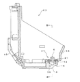
以下、本発明の好ましい実施形態について、添付図面を参照して説明する。図1は本発明の一実施形態としての継手部材を用いるカラーインクジェットプリンタの全体的な構成を示した概略斜視図である。 Hereinafter, preferred embodiments of the present invention will be described with reference to the accompanying drawings. FIG. 1 is a schematic perspective view showing an overall configuration of a color ink jet printer using a joint member according to an embodiment of the present invention.
〔全体構成〕
図1に示すカラーインクジェットプリンタ100のインクジェットヘッド63は、その本体フレーム68に、四色(例えば、シアン、マゼンタ、イエロー、ブラック)のインクを噴射させるために各色ごとに配設された計四個の圧電式のインクジェットヘッドユニット(以下「ヘッドユニット」)6を固着し、更に、カラーインクがそれぞれ充填される計四個のインクカートリッジ61を本体フレーム68に着脱可能に取り付けた構成としている。この本体フレーム68は、駆動機構65により直線方向に往復駆動されるキャリッジ64に固着されている。用紙を送るためのプラテンローラ66は、その軸線がキャリッジ64の往復移動方向に沿うよう配置され、ヘッドユニット6と対向して配置されている。
〔overall structure〕
The
キャリッジ64は、プラテンローラ66の支軸と平行に配設されるガイド軸71およびガイド板72によって、摺動自在に支持される。ガイド軸71の両端部の近傍にはプーリー73・74が支持され、これらのプーリー73・74の間に無端ベルト75が掛け渡される。前記のキャリッジ64はこの無端ベルト75に固定される。
The
このような駆動機構65の構成において、一方のプーリー73がモータ76の駆動により正逆回転されると、それに伴ってキャリッジ64がガイド軸71およびガイド板72に沿って直線方向に往復駆動され、インクジェットヘッド63の往復移動を行わせる。
In such a configuration of the
用紙62は、インクジェットプリンタ100の側方に設けられた給紙カセット(図示せず)から給紙され、ヘッドユニット6とプラテンローラ66との間の空間に導かれて、ヘッドユニット6から噴射されるインクにより所定の印字がなされた後に排紙される。なお、図1においては、用紙62の給紙機構および排紙機構の図示を省略している。
The
パージ機構67は、前記ヘッドユニット6の内部に溜まる気泡やゴミなどを含んだ不良インクを強制的に吸引して除去するためのものである。このパージ機構67はプラテンローラ66の側方に設けられ、前述の駆動機構65によってインクジェットヘッド63がリセット位置に至ったときにそのヘッドユニット6に対向するよう、該パージ機構67の配設位置が定められている。このパージ機構67はパージキャップ81を備えており、ヘッドユニット6の下面に設けられる多数のノズルを覆うように、当該ヘッドユニット6の下面に対し当接する。
The
この構成で、インクジェットヘッド63がリセット位置にあるときに、このキャリッジ64に設けられているヘッドユニット6のノズルをパージキャップ81で覆って、ヘッドユニット6の内部に溜まる気泡などを含んだ不良インクを、カム83の駆動によりポンプ82によって吸引して廃インク溜め84へ廃棄することにより、ヘッドユニット6の復旧を行うようにしている。なお、図1に示すキャップ85は、印字が終了してリセット位置に戻されるキャリッジ64上のヘッドユニット6の多数のノズルを覆って、インクの乾燥を防止するためのものである。
With this configuration, when the
〔インクジェットヘッドの構成〕
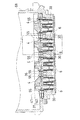
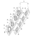
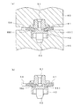
次に、インクジェットヘッド63を説明する。図2はインクジェットヘッドの断面図である。図3は図2におけるIII-III線断面図である。図4はヘッドユニットの分解斜視図である。図5は図3で鎖線で囲まれた部分の拡大図である。
[Configuration of inkjet head]
Next, the
インクジェットヘッド63の断面図が図2に示され、該インクジェットヘッド63の本体フレーム68は、図2に示すようにその上面側が開放された略箱状に形成されており、その開放された側から四つのインクカートリッジ61を着脱自在に装着できるようにして、搭載部を構成している。図2のIII-III線断面図である図3に示すように、本体フレーム68の底板5の下面には、前述のヘッドユニット6が四つ並べて接着剤で固着されている。
A sectional view of the
このヘッドユニット6の構成を示す斜視図が図4に示される。ヘッドユニット6は特開2001−246744号公報に記載のものと同様に、複数枚の薄い金属板を積層させた構成のキャビティプレート組10を有し、該キャビティプレート組10に対してプレート型の圧電アクチュエータ(以下「アクチュエータ」)20が、接着剤または接着シートを介して接着、積層されている。アクチュエータ20の上面には、外部機器との電気的接続のためのフレキシブルフラットケーブル40が、接着剤にて重ね接合されている。
A perspective view showing the configuration of the
キャビティプレート組10の下面にはノズル15が並べて多数開口されており、各ノズル15から下向きにインクが噴射するようになっている。また、キャビティプレート組10の上面には多数の圧力室16が並べて凹設されており、前述のノズル15は、対応する圧力室16に対し、キャビティプレート組10内に形成された図示しない連絡孔を介してそれぞれ接続されている。
A large number of
アクチュエータ20の詳細な構成は図示しないが上記公報に記載のものと同様に、キャビティプレート組10に形成される圧力室16の一つ一つに対応して設けられる駆動電極と、すべての圧力室16に共通の共通電極とで、圧電シートを挟んだ、公知の構成とされている。この構成で任意の駆動電極と共通電極との間に電圧を印加すると、圧電シートが変形して、対応する位置の圧力室16の容積を縮小させ、圧力室16内部のインクに噴射エネルギーを付与してインクをノズル15から噴射させる。
Although the detailed configuration of the
複数の圧力室16にインクを分配するための二つの共通インク室7・7がキャビティプレート組10内部に形成され、この各共通インク室7・7に繋がるインク供給口19・19が、キャビティプレート組10上面に開口されている。この二つのインク供給口19・19に対応させて、キャビティプレート組10の上面には二つの樹脂製あるいは金属製の筒状部材35・35が、接着剤(例えば、エポキシ系のもの)にて接着されて設けられる。筒状部材35は本体フレーム68側に向け突出した状態に設けられており、それぞれの筒状部材35の内部空間は、対応するインク供給口19に接続される。
Two
図2・図3に示すように、本体フレーム68の前記搭載部の一側部位において、各ヘッドユニット6に対応させた四つの貫通孔30が、底板5を貫通させて上下方向に設けられる。そして、この四つの貫通孔30に跨るように、単一の継手部材31が底板5の上面に固定されている。図3の鎖線で囲った部分の拡大図である図5に示すように、継手部材31は合成樹脂製の上半部(第1の部材)41と下半部(第2の部材)42を互いに接合した接合体として構成され、その内部には、前記各ヘッドユニット6に対応させてインク供給通路4がそれぞれ形成されている。
As shown in FIGS. 2 and 3, four through
上半部41の内部には各ヘッドユニット6に対応させて第1の流路51が一本形成されており、また、下半部42の内部には第2の流路52が二本形成されている。この構成で上半部41と下半部42とを向き合わせて接合することで、第1の流路51と第2の流路52とが互いに連通し、継手部材31の内部で逆「Y」字状に分岐されたインク供給通路4が構成される。前記第1の流路51は、図示しないインク供給源(具体的には、前述のインクカートリッジ61内のインクタンク)へ接続している。また、前記第2の流路52は、いずれも前記貫通孔30を通過してヘッドユニット6側へ延出され、ヘッドユニット6側に向けて継手部材31に二股状に突出形成した筒状部分32・32の内部を通過し、該筒状部分32・32の下端にそれぞれ開口される。
One
図5に示すように、ヘッドユニット6の筒状部材35と、継手部材31の筒状部分32とは、チューブ33・33によって接続されている。このチューブ33・33は弾性変形可能な素材(例えば、ゴム)で、円筒状に形成されている。チューブ33の一端は継手部材31の筒状部分32の外周に、他端は、ヘッドユニット6に固着された筒状部材35の外周に、それぞれ嵌合されている。
As shown in FIG. 5, the
ヘッドユニット6の筒状部材35と、継手部材31の筒状部分32は、いずれもその外径がチューブ33の内径よりも大きく設定されており、チューブ33の径を拡げるよう弾性変形させながら、筒状部材35および筒状部分32に嵌合させている。このようにしてチューブ33を組み付けることで、チューブ33の縮径方向の復元力が筒状部材35あるいは筒状部分32に対する締付け力として働き、嵌合部分が密着されてシール作用を営み、インクの漏れが防止される。また、継手部材31を本体フレームの底板5に固着したときチューブ33によりヘッドユニット6に曲げ力が作用することのないように、チューブ33に対し筒状部材35が嵌合される。
Both the
〔継手部材の接合構成〕
次に、継手部材31の上半部41と下半部42の接合構成を説明する。上述したとおり、継手部材31は上半部41と下半部42の二つの半部を向き合わせて接合し固着した構成とされる。上半部41と下半部42は、その互いに対向する面(接合面。図5における符号36)同士を向き合わせて接触させたときに、両半部41・42の間に空隙55が形成されるように、その形状を設定してある。そして、この空隙55に樹脂を射出して流し込み固化させることによって、両半部41・42を互いに剥離しないよう接合して固着している。
[Joint structure of joint members]
Next, the joining configuration of the
上半部41は射出成形により製造されており、図示しない第一の雌雄型間に樹脂を射出して、その内部に前記第1の流路51を形成するように、また、その接合面36に前記空隙55の一部を構成する凹部を形成するようにしている。また、このとき、上半部41には、前記空隙55から流れ出た樹脂の流路を外部空間に連通させる確認用窓58(図6参照)が形成される(第1の工程)。なお、後述するように、確認用窓58は、前記空隙55内における樹脂の流れ込み状況を確認するために利用される。
The
下半部42も同様に射出成形により製造されており、図示しない第二の雌雄型間に樹脂を射出して、その内部に前記第2の流路52を形成するように、また、その接合面36に前記空隙55の一部を構成する凹部を形成するようにしている(第2の工程)。なお、この下半部42側の凹部は、図6に符号56で示されている。
Similarly, the
本実施形態ではこのように、上半部41と下半部42とを別々に射出成形で製造する方法を採用しているので、上半部41と下半部42それぞれに、内部の流路(上半部41においては第1の流路51,下半部42においては第2の流路52)をそれぞれ別個独立に形成することができる。従って、例えば本実施形態のような第2の流路52の数が第1の流路51の数よりも多い流路形状も、継手部材31内部に簡単に形成することができる。また、射出成形を採用することで、両半部41・42を容易に短時間で製造でき、生産性が高められるほか、前記両半部41・42を寸法精度良く形成できるので、継手部材31の寸法のバラつきも抑制できる。
In this embodiment, since the method of separately manufacturing the
上半部41と下半部42とを接合させたときに内部に形成される前記空隙55の詳細な形状は、図7の斜視図でハッチングを付した部分として表される。この図7に示すように前記空隙55は、前記第1の流路51および第2の流路52を取り囲むトラック状のループ部55Lと、該ループ部55Lに接続する注入経路55I及び空気逃がし経路55Oと、前記ループ部55Lの両端部の上下面に形成される円錐部55Cと、を有している。注入経路55I及び空気逃がし経路55Oは、その一端を前記ループ部55Lに接続させる一方、他端は前記継手部材31の側部に開口を形成するようにしている。
The detailed shape of the
円錐部55Cは上半部41と下半部42の双方に形成されるものであり、いずれの半部41・42においても円錐部55Cは、一側を前記ループ部55Lに接続し、他側を前記接合面36と反対側の面に開口するよう形成されている。円錐部55Cは、前記接合面36と平行な面で切った断面積が、接合面36から離れるに従って大きくなる形状に形成されている。
The
そして、図8(a)に示すように、両半部41・42同士を向き合わせ、互いの接合面36同士を接触させて、上下方向から一対の型60で両半部41・42を挟み込んだ状態で、前記注入経路55Iから流動状の樹脂を射出する(第3の工程)。このとき、ループ部55L内の空気は空気逃がし経路55Oを通じて排出されるので、ループ部55L内にスムーズに樹脂を充填させることができる。また、樹脂はループ部55Lを経由して円錐部55Cにも至るが、円錐部55Cは上述するように接合面36と反対側に開口を有しているので、円錐部55C内部の空気は樹脂に押し出される形となって、当該開口を通じて排出される。従って、円錐部55C内にもスムーズに樹脂を充填させることができる。なお、前記ループ部55Lの内周に接するように、下半部42の前記接合面36にはトラック状の壁部57が凸状に形成されている(図5・図6参照)。該壁部57は、樹脂充填の際に、樹脂が第1の流路51及び第2の流路52に流れ込まないように作用する。
Then, as shown in FIG. 8 (a), the
その後、前記空隙55内に注入された樹脂が固化すると、図8(b)に示すように、両半部41・42を挟み込んでいた型60が外される。そして、上半部41の確認用窓58から前記空隙55内における樹脂の流れ込み状況が確認される(第4の工程)。ここで、確認用窓58は、図7および図9に示すように、前記空隙55から流れ出た樹脂の流路、つまり、上半部41の空気逃がし経路55Oよりも樹脂の流れ方向下流側に対応するように形成されている。したがって、注入経路55Iから注入された樹脂は、ループ部55Lを通過して空気逃がし経路55Oに到達し、その後、空気逃がし経路55Oから確認用窓58から見える範囲に流れ出す。このように、前記空隙55から流れ出た樹脂の流路の状況に基づいて、前記空隙55内における樹脂の流れ込み状況を推測することができる。
Thereafter, when the resin injected into the
次に、上半部41の確認用窓58から前記空隙55内における樹脂の流れ込み状況を確認した際の様子について、図9(a)〜図9(c)を参照して説明する。図9(a)〜(c)には、上半部41の上面図が示されている。ここで、本実施の形態では、確認用窓58から前記空隙55内における樹脂の流れ込み状況を確認したときの確認用窓58からの樹脂の見え方に基づいて、上半部41と下半部42との接合状態が判定される。なお、図9では、樹脂がある部分は斜線で図示されている。
Next, how the resin flows in the
ここで、上半部41と下半部42とを型60で挟み込んだ状態で注入経路55Iから注入される樹脂量は、あらかじめ所定量に設定されている。すなわち、上半部41と下半部42とを適正に接合させるために、前記空隙55内に注入すべき樹脂量が設定されている。なお、本実施の形態では、注入経路55Iから注入する樹脂量としては、注入経路55Iから注入された樹脂が、ループ部55L内および円錐部55C内に十分に注入されると共に、空気逃がし経路55Oを通過した樹脂の先端部(注入経路55Iから注入された樹脂であって空気逃がし経路55Oの延長線上に形成した下型60の溝に流れ込んだ樹脂の先端部)が確認用窓58から見える範囲に到達するような量が設定されている。
Here, the amount of resin injected from the injection path 55I in a state where the
したがって、樹脂を空隙55内に注入した後で型60を外したときに、図9(a)に示すように、樹脂の先端部が確認用窓58から確認される場合には、上半部41と下半部42との接合状態が適正であると判定される。このように、本実施の形態では、確認用窓58からの樹脂の見え方に基づいて、上半部41と下半部42との接合状態が判定されるので、略矩形状の確認用窓58の樹脂の流れ方向に沿う長さX(図7参照)は、樹脂の注入量および上半部41と下半部42との接合状態等を考慮して設定しておくことが好ましい。すなわち、確認用窓58からの樹脂の見え方と空隙55内における樹脂の流れ込み状況との関係をあらかじめ把握すると共に、確認用窓58から樹脂がどのように見える場合に、上半部41と下半部42との接合状態が適正であるかを把握したうえで、確認用窓58の長さXを設定しておくことが好ましい。
Accordingly, when the
また、図9(b)および図9(c)は、上半部41と下半部42との接合状態が適正でないと判定される場合の様子が図示されている。図9(b)では、樹脂の先端部が確認用窓58から見える範囲に到達していないので、確認用窓58から樹脂(樹脂の先端部)が全く見えない。このように、確認用窓58から樹脂を確認することができない場合には、注入経路55Iから注入された樹脂が空隙55内の全体にまわらずに、第1の流路51および第2の流路52が外部とつながってしまう現象(流路のリーク)が発生していると考えられる。また、上述したように、所定量の樹脂が空隙55内に注入されるが、注入時の圧力、流速、温度、樹脂量などにバラツキが生じることによって、あらかじめ設定された所定量の樹脂が注入されない可能性がある。そして、注入される樹脂が所定量よりも少ない場合にも、確認用窓58から樹脂を確認することができなくなると考えられる。
FIG. 9B and FIG. 9C illustrate a state where it is determined that the joining state of the
一方、図9(c)では、樹脂の先端部が確認用窓58から見える範囲を通過しており、確認用窓58から樹脂の先端部を確認することができない。このように、確認用窓58から樹脂を確認することはできるが樹脂の先端部を確認することが出来ない場合には、注入経路55Iから樹脂が比較的速い流速で注入されて、上半部41と下半部42が溶けたり変形したりすることによって、第1の流路51および第2の流路52と空隙55とが連通してしまい、第1の流路51および第2の流路52内に樹脂が流れ込んで短路流路を作ってしまう現象(流路の詰まり)が発生していると考えられる。
On the other hand, in FIG. 9C, the resin tip passes through a range visible from the
以上説明したように、ループ部55Lと円錐部55Cに注入された樹脂は、いったん固化すると、円錐部55C内の部分が変形したり円錐部55Cとループ部55Lとの接続部分が折れたりしない限り、それぞれの半部41・42からループ部55Lが離れないことになる。これは、二つの半部41・42同士がループ部55Lを介して機械的に強固に且つ安定して接合され、意図に反する剥離を確実に防止できることを意味する。
As described above, once the resin injected into the
また、空隙55は第1の流路51・第2の流路52を囲む前記ループ部55Lを有するから、当該ループ部55Lがインク漏れを防止するシールの役割を果たす。この結果、第1の流路51・第2の流路52を取り囲むように前記接合面36が封止されることになるので、継手部材31内部の流路にインク供給源からのインクが流入した場合においても、接合面36からインクが漏洩することを防止できる。この結果、インク漏れを確実に防止したインクジェットヘッド63を得ることができる。
Further, since the
また、上半部41と下半部42とを型60で挟み込んだ状態で、注入経路55Iから樹脂を注入した後で、上半部41の確認用窓58から空隙55内における樹脂の流れ込み状況を例えば目視観察により把握することができる。そのため、上半部41と下半部42との接合状態の良し悪しを容易に確認することができる。その結果、上半部41と下半部42との接合状態の良し悪しを確認するために、つまり、上半部41および下半部42の内部に流路が形成されている場合に、流路のリークや流路の詰まり等の有無を確認するために、煩雑な検査を行う必要がなくなる。その結果、インクジェットヘッド63の製造に要する時間が短縮されると共に、コストを低減することができる。
In addition, after the resin is injected from the injection path 55I with the
空隙55内部に射出する樹脂は様々なものが考えられるが、円錐部55C内の樹脂の容易な変形を防止する観点からは、固化後に十分な剛性および機械的強度を呈するものが望ましい。また、前記空隙55に射出する樹脂によって、上半部41と下半部42の空隙55を形成している部分(前記凹部)が溶融されることとなるように、当該樹脂との関係で前記半部41・42の材料を定めることが望ましい。射出される樹脂と空隙55の表面とが溶け合うことによって、両半部41・42の接合を更に強固とできるからである。また、この結果として接合部の応力を分散できるから、前記円錐部55Cの根元への応力集中が回避され、円錐部55Cの根元の折損を回避でき、これによっても、両半部41・42の接合を更に強固とできる。また、特にループ部55Lの部分が空隙55の表面と一体化することで、シール性に一層優れ、インク漏れをより確実に防止できる。
Various resins can be injected into the
あるいは、前記半部41・42が熱可塑性樹脂を素材とする場合は、空隙55に射出する樹脂の温度を前記半部41・42が溶融し得る温度に設定すると、同様の効果を得ることができる。ただし温度が高すぎると上半部41・下半部42の全体が変形してしまうなどの不具合が考えられるので、上記の事情を考慮して、適当な温度を設定するようにする。
Or when the said
空隙55内部に射出される樹脂については、当該射出時に粘度が低すぎると、接合面36において上半部41・下半部42間に形成される微少な隙間を介して内部の第1の流路51・第2の流路52内に樹脂が流れ出し、インク流を妨げるおそれがあるので、そのような事情も考慮して射出時の樹脂の粘度を調整するのが好ましい。
As for the resin injected into the
好ましくは、空隙55に射出する樹脂は、前記半部41・42の素材である樹脂と同一とするのが良い。このように同一材質とすると、空隙55の表面と樹脂とが馴染み良く一体化するので、両半部41・42の接合を更に強固とすることができる。また、円錐部55Cの根元部への応力集中も、前述と同様に回避できる。更には、特にループ部55Lの部分が空隙55の表面と一体化することで、シール性に一層優れ、インク漏れをより確実に防止できることとなる。
Preferably, the resin injected into the
前記空隙55の形状としては、円錐部55Cを有する形状としているが、この部分は円錐状とすることに限らず、角錐状、キノコ状、楔状等の任意の形状を採用できる。要は、接合面36から接合面36に交差する方向に離れるに従って、その断面積が大きくなるような形状となっていれば良い。更に言えば、前記上半部41・下半部42を空隙55に樹脂を流し込むための型に見立てたときに、いわゆるアンダカット部に相当する部分を当該空隙55が有していれば、接合を強固とできる効果を発揮し得る。ただし本実施形態の円錐部55Cのように、断面積が接合面から離れるに従って連続的に増大する形状とすると、樹脂を空隙55に射出する工程(前記第3の工程)において、空気を容易に逃がしながら射出樹脂を当該円錐部55C内にスムーズに流して充填できる点で好ましい。
The shape of the
前記円錐部55Cの数や配置も、本実施形態に示したものに限定されない。ただし、円錐部55Cは上半部41・下半部42の双方に少なくとも一つずつ形成した方が、一方にのみ形成する場合よりも、両半部41・42同士を一層強固に接合することができる。
The number and arrangement of the
前記空隙55のループ部55Lの形状としては、トラック状に限らず、円状や楕円状、四角形状などの任意の形状を採用できる。また、前記第1の流路51・第2の流路52を取り囲んでいれば良く、必ずしも閉じた形状に限定されず、開いた形状としても良い(例えば、「C」字状)。ただし、前述のインク漏れの防止を確実とする観点からは、本実施形態のように、切れ目のない閉じたループ状とすることが好ましい。
The shape of the
上半部41に形成される確認用窓58の形状としては、略矩形状に限らず、円状や楕円状などの任意の形状を採用できる。また、上半部41に形成される確認用窓58は、1つであってもよいし、複数であってもよい。また、確認用窓58は、必ずしも空隙55から流れ出た樹脂の流路を外部空間に連通させるように形成される必要はなく、空隙55を外部空間に連通させるように形成されてもよい。また、確認用窓58は、下半部442に形成されていてもよい。
The shape of the
本実施形態では単一の継手部材31に四つのインク供給通路4を形成し、一つのインク供給通路4に対応させて前記空隙55を一つ形成させる構成となっている。しかしながらこれに限らず、ヘッドユニット6が四つあるのに対応させて四つの継手部材31を配置し、一つの継手部材31につき一つのインク供給通路4を形成する構成としても良い。この場合は、四つの継手部材31のそれぞれが上半部41・下半部42を有するようにし、上述の空隙55に樹脂を射出することで両半部41・42を接合するようにする。また、本実施形態ではインクジェットヘッドの継手部材31に接合体を適用した例を示したが、本発明の接合体はこれに限ることなく、内部に流路を形成するとしないとを問わず、また、インクジェット印字分野であると否とを問わず、ある部材と他の部材とを接合する一般的な構成(例えば、金属と金属とを接合または金属と樹脂とを接合する構成)にこれを適用することができる。
In the present embodiment, four
31 継手部材(接合体)
36 接合面
41 上半部(第1の部材)
42 下半部(第2の部材)
51 第1の流路
52 第2の流路
55 空隙
55C 円錐部(接合面に交差する方向に接合面から離れるに従って断面積が大きくなる領域)
58 確認用窓(孔)
31 Joint members (joints)
36 Joining
42 Lower half (second member)
51
58 Confirmation window (hole)
Claims (11)
前記空隙は、前記接合面近傍において前記第1の流路および前記第2の流路を囲むように形成されており、
前記第2の部材の接合面に、当該接合面と交差する方向から見て、前記空隙の内周に接し且つ前記第1の流路及び前記第2の流路を囲むように配置された、凸状の壁部が形成されており、
前記空隙は、前記接合面に交差する方向に前記接合面から離れるに従って、その断面積が大きくなるような領域を有することを特徴とする接合体。 The first channel and the second channel communicate with each other with the first member having the first channel formed therein and the second member having the second channel formed therein. In the joined body for injecting resin into the gap formed in the joint surface between the first member and the second member to join the first member and the second member,
The gap is formed so as to surround the first flow path and the second flow path in the vicinity of the joint surface ,
The second member is disposed on the joint surface so as to be in contact with the inner periphery of the gap and surround the first flow channel and the second flow channel as viewed from the direction intersecting the joint surface. A convex wall is formed,
The bonded body is characterized in that the gap has a region whose cross-sectional area increases as the distance from the bonded surface increases in a direction intersecting the bonded surface .
前記第2の流路は、前記第1の流路の数より多い数の流路からなることを特徴とする接合体。 The joined body according to claim 1 ,
Said 2nd flow path consists of a larger number of flow paths than the number of said 1st flow paths, The joined body characterized by the above-mentioned.
前記空隙が、
前記接合面近傍において前記第1の流路および前記第2の流路を囲む環状部と、
前記環状部に連通し且つ前記環状部の外側に向かって延在する2つの延在部であって、一方が樹脂の入口側となり他方が樹脂の出口側となる2つの延在部とを有していると共に、
前記第1の部材には、前記出口側の延在部および前記出口側の延在部から流れ出た樹脂の流路のいずれかを外部空間に連通させる孔が形成されていることを特徴とする接合体。 In the joined body according to claim 1 or 2 ,
The void is
An annular portion surrounding the first flow path and the second flow path in the vicinity of the joint surface;
Two extending portions that communicate with the annular portion and extend toward the outside of the annular portion, each having two extending portions, one on the resin inlet side and the other on the resin outlet side. As well as
The first member is formed with a hole for communicating any one of the extending portion on the outlet side and the flow path of the resin flowing out from the extending portion on the outlet side with the external space. Joined body.
前記第1の部材と前記第2の部材は、樹脂からなることを特徴とする接合体。 In the joined body according to any one of claims 1 to 3 ,
The first member and the second member are made of resin.
前記第1の部材と前記第2の部材は、前記空隙に射出する樹脂によって、その空隙を形成している部分が溶融される材料であることを特徴とする接合体。 The joined body according to claim 4 ,
The first member and the second member are made of a material in which a part forming the gap is melted by the resin injected into the gap.
前記第1の部材と前記第2の部材は、前記空隙に射出する樹脂と同一の材質からなることを特徴とする接合体。 The joined body according to claim 5 ,
The first member and the second member are made of the same material as the resin injected into the gap.
第2の雌雄型間に樹脂を射出して内部に前記第1の流路に連通する第2の流路を形成した第2の部材を形成する第2の工程と、
前記第1の部材と前記第2の部材とを向き合わせ、その接合面近傍において前記第1の流路および前記第2の流路を囲むように形成された空隙に樹脂を射出して、前記第1の部材と前記第2の部材とを接合する第3の工程と、を備えており、
前記第2の工程において、前記第2の部材の接合面に、前記第1の部材と前記第2の部材を向き合わせた状態で、当該接合面と交差する方向から見て、前記空隙の内周に接し且つ前記第1の流路及び前記第2の流路を囲むように配置される、凸状の壁部を形成し、
前記第1の工程及び前記第2の工程において、それぞれ、前記第1の部材と前記第2の部材を向き合わせた状態で、前記空隙が、前記接合面に交差する方向に前記接合面から離れるに従って、その断面積が大きくなるような領域を有するように、前記第1の部材及び前記第2の部材を形成することを特徴とする接合体の製造方法。 A first step of forming a first member in which a first flow path is formed by injecting resin between the first and second dies;
A second step of forming a second member that injects a resin between the second male and female molds to form a second flow path that communicates with the first flow path inside;
The first member and the second member face each other, and a resin is injected into a gap formed so as to surround the first flow path and the second flow path in the vicinity of the joint surface, And a third step of joining the first member and the second member ,
In the second step, in the state where the first member and the second member face each other on the joint surface of the second member, the inside of the gap is viewed from the direction intersecting the joint surface. Forming a convex wall portion arranged in contact with the circumference and surrounding the first flow path and the second flow path;
In the first step and the second step, the gap is separated from the joint surface in a direction intersecting the joint surface in a state where the first member and the second member face each other. According to the method, the first member and the second member are formed so as to have a region in which the cross-sectional area becomes large .
前記第1の工程が、前記第1の部材に対して、前記空隙および前記空隙から流れ出た樹脂の流路のいずれかを外部空間に連通させる孔を形成する工程を含んでおり、
前記第1の部材に形成された前記孔から、前記空隙内および前記空隙から流れ出た樹脂の流路内のいずれかにおける樹脂の流れ込み状況を確認する第4の工程をさらに備えていることを特徴とする接合体の製造方法。 In the manufacturing method of the joined object according to claim 7 ,
The first step includes a step of forming a hole for communicating any one of the gap and the resin flow path flowing out of the gap with an external space with respect to the first member;
The method further comprises a fourth step of confirming a flow state of the resin in either the gap or the resin flow path flowing out of the gap from the hole formed in the first member. A method for manufacturing a joined body.
前記空隙が、
前記接合面近傍において前記第1の流路および前記第2の流路を囲む環状部と、
前記環状部に連通し且つ前記環状部の外側に向かって延在する2つの延在部であって、一方が樹脂の入口側となり他方が樹脂の出口側となる2つの延在部とを有していると共に、
前記第1の工程が、前記第1の部材に対して、前記出口側の延在部および前記出口側の延在部から流れ出た樹脂の流路のいずれかを外部空間に連通させる孔を形成する工程を含んでおり、
前記第1の部材に形成された前記孔から、前記出口側の延在部内および前記出口側の延在部から流れ出た樹脂の流路内のいずれかにおける樹脂の流れ込み状況を確認する第4の工程をさらに備えていることを特徴とする接合体の製造方法。 In the manufacturing method of the joined object according to claim 7 ,
The void is
An annular portion surrounding the first flow path and the second flow path in the vicinity of the joint surface;
Two extending portions that communicate with the annular portion and extend toward the outside of the annular portion, each having two extending portions, one on the resin inlet side and the other on the resin outlet side. As well as
In the first step, a hole is formed in the first member so that either the extended portion on the outlet side or the resin flow channel flowing out from the extended portion on the outlet side communicates with the external space. Including the step of
Confirming the state of the resin flowing in either the outlet-side extension part or the resin-flow path flowing out of the outlet-side extension part from the hole formed in the first member The manufacturing method of the conjugate | zygote further provided with the process.
インク供給源から前記インク供給口に至るインク流路の少なくとも一部をなすインク供給通路を内部に形成した、継手部材と、を備えるとともに、
前記継手部材は、請求項1から請求項3までの何れか一項に記載の接合体によって構成されることを特徴とするインクジェットヘッド。 A head unit having a plurality of nozzles for ejecting ink to the printing surface, and an ink supply port communicating with the nozzles;
A coupling member formed inside an ink supply passage that forms at least a part of an ink flow path from an ink supply source to the ink supply port, and
The joint member, the ink-jet head, characterized in that it is constituted by assembly according to any one of claims 1 to 3.
前記ヘッドユニットは、複数列の前記ノズルと、そのノズル列に対応した複数のインク供給口とを有し、
前記継手部材は、請求項2に記載の接合体によって構成され、
前記インク供給源側に位置する前記第1の部材は、前記第1の流路を有し、
前記ヘッドユニット側に位置する前記第2の部材は、前記複数のインク供給口に対応した複数の前記第2の流路を有することを特徴とするインクジェットヘッド。 In the inkjet head according to claim 10 ,
The head unit has a plurality of nozzles and a plurality of ink supply ports corresponding to the nozzle rows,
The joint member is constituted by the joined body according to claim 2 ,
The first member located on the ink supply source side includes the first flow path,
The inkjet head, wherein the second member located on the head unit side has a plurality of the second flow paths corresponding to the plurality of ink supply ports.
Priority Applications (1)
| Application Number | Priority Date | Filing Date | Title |
|---|---|---|---|
| JP2003405868A JP4432477B2 (en) | 2003-01-09 | 2003-12-04 | Bonded body, manufacturing method of bonded body, and inkjet head |
Applications Claiming Priority (2)
| Application Number | Priority Date | Filing Date | Title |
|---|---|---|---|
| JP2003002955 | 2003-01-09 | ||
| JP2003405868A JP4432477B2 (en) | 2003-01-09 | 2003-12-04 | Bonded body, manufacturing method of bonded body, and inkjet head |
Publications (2)
| Publication Number | Publication Date |
|---|---|
| JP2004230881A JP2004230881A (en) | 2004-08-19 |
| JP4432477B2 true JP4432477B2 (en) | 2010-03-17 |
Family
ID=32964636
Family Applications (1)
| Application Number | Title | Priority Date | Filing Date |
|---|---|---|---|
| JP2003405868A Expired - Fee Related JP4432477B2 (en) | 2003-01-09 | 2003-12-04 | Bonded body, manufacturing method of bonded body, and inkjet head |
Country Status (1)
| Country | Link |
|---|---|
| JP (1) | JP4432477B2 (en) |
Families Citing this family (3)
| Publication number | Priority date | Publication date | Assignee | Title |
|---|---|---|---|---|
| JP5435962B2 (en) * | 2009-01-07 | 2014-03-05 | キヤノン株式会社 | Liquid jet recording head and method for manufacturing liquid jet recording head |
| JP2010188536A (en) * | 2009-02-16 | 2010-09-02 | Seiko Epson Corp | Liquid ejecting head, manufacturing method thereof, and liquid ejecting apparatus |
| JP5430718B2 (en) * | 2012-07-19 | 2014-03-05 | キヤノン株式会社 | Liquid discharge head and method of manufacturing the liquid discharge head |
-
2003
- 2003-12-04 JP JP2003405868A patent/JP4432477B2/en not_active Expired - Fee Related
Also Published As
| Publication number | Publication date |
|---|---|
| JP2004230881A (en) | 2004-08-19 |
Similar Documents
| Publication | Publication Date | Title |
|---|---|---|
| JP4193435B2 (en) | Ink cartridge and ink filling method thereof | |
| JP5019061B2 (en) | Liquid ejecting head, manufacturing method thereof, and liquid ejecting apparatus | |
| JP5435962B2 (en) | Liquid jet recording head and method for manufacturing liquid jet recording head | |
| JP5472574B2 (en) | Liquid ejecting head, manufacturing method thereof, and liquid ejecting apparatus | |
| JP2002178541A (en) | Recording head unit | |
| US7862759B2 (en) | Method of manufacturing liquid ejecting head | |
| US7958634B2 (en) | Liquid ejecting head manufacturing method | |
| JP2009190278A (en) | Liquid jet head and method for manufacturing the same, and liquid jet device | |
| JP5019058B2 (en) | Liquid ejecting head, manufacturing method thereof, and liquid ejecting apparatus | |
| JP5257133B2 (en) | Liquid ejecting head manufacturing method, liquid ejecting head, and liquid ejecting apparatus | |
| TWI547384B (en) | Multi-part fluid flow structure | |
| JP4810861B2 (en) | Liquid supply member and liquid ejecting apparatus | |
| JP5618052B2 (en) | Liquid ejecting head and liquid ejecting apparatus | |
| EP1336497B1 (en) | Ink-jet printhead and method of manufacturing the same | |
| JP7057111B2 (en) | Manufacturing method of sealing mechanism | |
| JP4432477B2 (en) | Bonded body, manufacturing method of bonded body, and inkjet head | |
| JP2009113250A (en) | Liquid jetting head and liquid jetting apparatus | |
| JP4193891B2 (en) | Ink cartridge and ink filling method thereof | |
| US8337005B2 (en) | Liquid ejecting head, liquid ejecting head unit and liquid ejecting apparatus | |
| JP2003305873A (en) | Ink jet printer head and production method therefor | |
| JP5472595B2 (en) | Liquid ejecting head and liquid ejecting apparatus | |
| JP2012254551A (en) | Liquid injection head and liquid injection device | |
| JP2009196292A (en) | Method for fabricating filter assembly, and inkjet head | |
| JP2004284239A (en) | Liquid jet head | |
| JP2010099985A (en) | Method for manufacturing liquid jetting head |
Legal Events
| Date | Code | Title | Description |
|---|---|---|---|
| A621 | Written request for application examination |
Free format text: JAPANESE INTERMEDIATE CODE: A621 Effective date: 20061201 |
|
| A977 | Report on retrieval |
Free format text: JAPANESE INTERMEDIATE CODE: A971007 Effective date: 20090210 |
|
| A131 | Notification of reasons for refusal |
Free format text: JAPANESE INTERMEDIATE CODE: A131 Effective date: 20090224 |
|
| A521 | Written amendment |
Free format text: JAPANESE INTERMEDIATE CODE: A523 Effective date: 20090427 |
|
| TRDD | Decision of grant or rejection written | ||
| A01 | Written decision to grant a patent or to grant a registration (utility model) |
Free format text: JAPANESE INTERMEDIATE CODE: A01 Effective date: 20091201 |
|
| A01 | Written decision to grant a patent or to grant a registration (utility model) |
Free format text: JAPANESE INTERMEDIATE CODE: A01 |
|
| A61 | First payment of annual fees (during grant procedure) |
Free format text: JAPANESE INTERMEDIATE CODE: A61 Effective date: 20091214 |
|
| R150 | Certificate of patent or registration of utility model |
Ref document number: 4432477 Country of ref document: JP Free format text: JAPANESE INTERMEDIATE CODE: R150 Free format text: JAPANESE INTERMEDIATE CODE: R150 |
|
| FPAY | Renewal fee payment (event date is renewal date of database) |
Free format text: PAYMENT UNTIL: 20130108 Year of fee payment: 3 |
|
| FPAY | Renewal fee payment (event date is renewal date of database) |
Free format text: PAYMENT UNTIL: 20140108 Year of fee payment: 4 |
|
| LAPS | Cancellation because of no payment of annual fees |