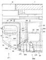
以下、本発明を実施するための形態について、添付図面を参照しながら説明する。本発明に係る球抜き機構を備えた遊技機の一例として、図1に第1構成形態の球抜き機構BM1を備えたパチンコ機PMにおけるガラス扉5および上球皿構造体6を開放した状態の正面図を示しており、まずこの図面を参照してパチンコ機PMの全体概要について説明する。なお、以降では、種々の構成形態の球抜き機構BMについて順次説明してゆくが、パチンコ機本体の基本構成および灰皿構造ATの構成は同様であり、各構成形態におけるパチンコ機PMの正面図、および灰皿構造ATを示す各図では同一部分に同一番号を付して重複説明を省略する。
Hereinafter, embodiments for carrying out the present invention will be described with reference to the accompanying drawings. As an example of a gaming machine equipped with a ball removal mechanism according to the present invention, the glass door 5 and the upper ball dish structure 6 in the pachinko machine PM provided with the ball removal mechanism BM1 of the first configuration form in FIG. A front view is shown. First, an overall outline of the pachinko machine PM will be described with reference to this drawing. In the following, the ball punching mechanism BM of various configuration forms will be described in order, but the basic configuration of the pachinko machine body and the configuration of the ashtray structure AT are the same, and the front view of the pachinko machine PM in each configuration form, And in each figure which shows ashtray structure AT, the same number is attached | subjected to the same part and duplication description is abbreviate | omitted.
(パチンコ機の基本構成)
パチンコ機PMは、外郭方形枠サイズに構成されて縦向きの固定保持枠をなす外枠1の開口前面に、これに合わせた方形枠サイズに構成されて開閉搭載用の前枠2が互いの正面左側上下に配設されたヒンジ機構により前方に横開き開閉および着脱が可能に取り付けられ、正面右側に設けられた施錠装置4を利用して常には外枠1と係合連結された閉鎖状態に保持される。
(Basic configuration of pachinko machine)
The pachinko machine PM is configured to have a rectangular frame size and a front frame 2 configured to have a rectangular frame size corresponding to the opening front of the outer frame 1 that forms a vertically fixed holding frame. A closed state in which the hinge mechanism disposed on the upper left and right sides of the front side is attached to the front so that it can be opened / closed and attached / detached, and is always engaged with and connected to the outer frame 1 using the locking device 4 provided on the right side of the front side. Retained.
前枠2の前面上部には、前枠2の前面域に合わせた方形状のガラス扉5および上球皿構造体6が前方に横開き開閉および着脱可能に取り付けられ、正面右側に設けられた施錠装置4および球皿施錠装置を利用して前枠2の前面を覆う閉鎖状態に保持される。ガラス扉5の背面側に位置する前枠上部には、遊技盤7を着脱可能に収容保持する収容枠が設けられており、この収容枠に遊技盤7が立設姿勢で保持され常には閉鎖施錠されるガラス扉5に前面域を臨ませている。遊技盤7は、所定板厚の積層合板の表面にセルを貼り付けてルーター加工した化粧板を基板とし、帯板状の案内レールに囲まれた略円形の遊技領域内に、多数本の遊技釘とともに風車や各種の入賞具、遊技の展開状況に応じて図柄を表示させる画像表示装置、左右のサイドランプなどの遊技構成部品が取り付けられ、遊技領域の下端部にアウト口が設けられて構成される。
A rectangular glass door 5 and an upper ball tray structure 6 adapted to the front area of the front frame 2 are attached to the front upper part of the front frame 2 so as to be openable and detachable laterally forward and detachably. The locking device 4 and the ball tray locking device are used to hold the front frame 2 in a closed state that covers the front surface. The upper part of the front frame located on the back side of the glass door 5 is provided with a storage frame for detachably storing and holding the game board 7, and the game board 7 is held in a standing posture in this storage frame and is always closed. The glass door 5 to be locked faces the front area. The game board 7 has a decorative board obtained by applying a cell to a surface of a laminated plywood having a predetermined board thickness and router processing, and a large number of games in a substantially circular game area surrounded by strip-like guide rails. Along with nails, game components such as windmills, various prizes, image display devices that display symbols according to game development status, and left and right side lamps are attached, and an out port is provided at the lower end of the game area Is done.
前枠2の下部領域には、遊技盤7の直下に位置して遊技補助盤10が形成され、遊技盤7に向けて遊技球を発射する遊技球発射装置11、遊技領域に到達できずに戻ってきたファール球を回収して下球皿に流下させるファール球回収構造12、遊技の展開状況に応じた効果音を発生させるスピーカ13などが設けられている。遊技補助盤10は常には閉鎖施錠される上球皿構造体6に前面が覆われている。遊技補助盤10の下側には、遊技球発射装置の作動を操作する発射ハンドル14が設けられるとともに、前方に突出して下球皿構造体20が取り付けられている。
In the lower area of the front frame 2, a game auxiliary board 10 is formed immediately below the game board 7, and a game ball launcher 11 that launches a game ball toward the game board 7, without reaching the game area. A foul ball collection structure 12 that collects the returned foul balls and flows them down to the lower ball tray, a speaker 13 that generates sound effects according to the game development situation, and the like are provided. The front surface of the game auxiliary board 10 is covered with an upper ball tray structure 6 that is always closed and locked. A launch handle 14 for operating the operation of the game ball launcher is provided on the lower side of the game assisting board 10, and a lower ball tray structure 20 is attached so as to protrude forward.
前枠2の後面側には、裏セット盤が前枠2の後方に横開き開閉可能に取り付けられている。裏セット盤については詳細図示を省略するが、払い出し用の遊技球を貯留する球貯留タンク、球貯留タンクに貯留された遊技球を遊技盤における入賞状態に応じて払い出す球払出装置、球払出装置から払い出された褒賞品としての遊技球を上通出口16を介して上球皿に導く上球皿払出通路、および上球皿払出通路が充満された状態でさらに球払出装置から遊技球が払い出されたときに溢れ出る遊技球を下通出口17を介して下球皿23に導く下球皿払出通路などからなる賞球機構、ならびに入賞具に入賞したセーフ球およびアウト口から回収されたアウト球を遊技島側の回収バスケットに導く遊技済み球排出機構などが設けられている。また裏セット盤の背面には、主基板や払出制御基板などの各種回路基板が取り付けられており、各電装部品がコネクタケーブルで接続されてパチンコ機PMが構成される。
On the rear side of the front frame 2, a back set board is attached to the rear of the front frame 2 so as to be able to open and close laterally. Although the detailed illustration of the back set board is omitted, a ball storage tank that stores game balls for payout, a ball payout device that pays out game balls stored in the ball storage tank according to the winning state in the game board, ball payout An upper ball tray payout passage for guiding a game ball as a prize paid out from the device to the upper ball tray through the upper outlet 16 and a game ball from the ball payout device in a state where the upper ball tray discharge passage is filled. The game balls that overflow when the game is paid out are collected from a prize ball mechanism including a lower ball dish payout passage that guides the game balls to the lower ball dish 23 through the lower passage outlet 17, and the safe balls that are won in the prize-winning tool and the outlet. A game-completed ball discharge mechanism or the like for guiding the outball to the collection basket on the game island side is provided. Various circuit boards such as a main board and a payout control board are attached to the back of the back set board, and each electrical component is connected by a connector cable to constitute a pachinko machine PM.
以上のように概要構成されるパチンコ機PMにあって、前枠2の前面下部に突出して設けられた下球皿構造体20に、上方に開口して遊技球を貯留する下球皿23と、上面が開口した箱状の灰皿50を着脱自在に備える灰皿構造ATと、後に詳述する球抜き機構BMとが設けられている。
In the pachinko machine PM generally configured as described above, a lower ball tray 23 that opens upward and stores game balls is provided in a lower ball tray structure 20 that projects from the front lower portion of the front frame 2. An ashtray structure AT provided with a box-shaped ashtray 50 having an open top surface is detachably provided, and a ball removal mechanism BM described in detail later.
(灰皿構造AT1)
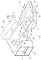
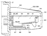
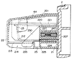
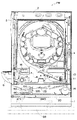
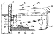
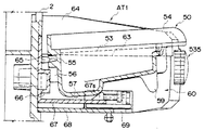
図2〜図4の各図に第1構成形態の灰皿構造AT1を示しており、これらの各図を参照して灰皿構造AT1について説明する。ここで、図2は灰皿構造AT1を左斜め前方から見た斜視図、図3は灰皿装着状態における灰皿中央部での側断面図、図4は灰皿着脱時における図3と同様位置の側断面図である。なお、灰皿構造AT1を含む球抜き機構BM1aの正面図を図9に、背面図を図10に、平面図を図11に示しており、これらの図面も適宜参照しながら説明する。
(Ashtray structure AT1)
2 to 4 show the ashtray structure AT1 of the first configuration form, and the ashtray structure AT1 will be described with reference to these drawings. Here, FIG. 2 is a perspective view of the ashtray structure AT1 as viewed obliquely from the left front, FIG. 3 is a side sectional view at the center of the ashtray with the ashtray mounted, and FIG. 4 is a side section at the same position as FIG. FIG. A front view of the ball removing mechanism BM1a including the ashtray structure AT1 is shown in FIG. 9, a rear view is shown in FIG. 10, and a plan view is shown in FIG. 11, which will be described with reference to these drawings as appropriate.
灰皿構造AT1は、その構成を大別すると、灰皿50と、この灰皿50を収容保持する収容凹部60とからなる。灰皿50は全体として上面開放の箱状で、前縁側が下球皿構造体20の外形輪郭線に合わせた円弧状に形成され、例えばメラミン樹脂やフェノール樹脂などの耐熱性を有する熱硬化性樹脂を加工成型し、若しくはアルミ合金等の金属材料をダイキャスト等により加工成形し、または樹脂材料で加工成形した本体部に薄板ステンレス鋼板等をプレス成形した容体部を嵌着固定するなどして図示する形態に形成される。吸い殻を収容する容体部は、前方が比較的浅く後方に向けて緩やかに深くなるもみ消し部51と、もみ消し部51の後方に一段深く形成された吸い殻貯留部52との2段構成になっている。容体部51,52の上部には前後左右に拡開されて額縁状の縁部53が形成され、前方の縁部の中央にはタバコの転動を防止するU字溝状のレスト部53gが形成され、後方および左右の縁部には容体部51,52の周囲を取り囲む囲壁部54が立設されている。
The ashtray structure AT1 is roughly composed of an ashtray 50 and an accommodating recess 60 that accommodates and holds the ashtray 50. The ashtray 50 has a box shape with an open top surface as a whole, and has a leading edge formed in an arc shape matching the outer contour of the lower ball tray structure 20, and has heat resistance such as melamine resin or phenol resin, for example. This is illustrated by processing and molding a metal material such as an aluminum alloy by die-casting, etc., or by fitting and fixing a body portion obtained by press-forming a thin stainless steel plate or the like to a main body portion processed and molded with a resin material. To form. The container portion that accommodates the cigarette butt has a two-stage configuration of a frosted portion 51 that is relatively shallow at the front and gently deeper toward the rear, and a butt shed storage portion 52 that is formed one step deeper behind the frosted portion 51. . A frame-shaped edge 53 is formed in the upper part of the container parts 51, 52 in the front / rear / left / right direction, and a U-shaped groove-shaped rest part 53g for preventing the cigarette from rolling is provided at the center of the front edge. An encircling wall portion 54 that surrounds the periphery of the container portions 51 and 52 is erected on the rear and left and right edges.
このため、図11に示すように、喫煙中のタバコを灰皿50に仮置きしたときに、仮置きされたタバコがレスト部53gに安定支持されて左右に転動したり灰皿の内外に落下するようなことがなく、また吸い殻貯留部52をもみ消し部51の後方に一段深く形成しているため、既に吸い殻貯留部52に収容された吸い殻が、仮置きされたタバコの火やもみ消されたタバコの火種から離れて配設され、燃え移りにくい構成になっている。さらに、容体部51,52の周囲を取り囲むように縁部53および囲壁部54を形成しているため、タバコの灰や火種の飛散を防止するとともに、囲壁部54が周辺構造を保護する防火壁としても機能し、一般的に熱可塑性樹脂を用いて形成される周辺構造物の熱変形を抑止した構成になっている。
For this reason, as shown in FIG. 11, when smoking tobacco is temporarily placed on the ashtray 50, the temporarily placed tobacco is stably supported by the rest portion 53g and rolls left and right or falls into and out of the ashtray. The cigarette butt already accommodated in the cigarette butt storage portion 52 was extinguished from the fire of the temporarily placed cigarette because the cigarette butt storage portion 52 was formed one step deeper behind the eradication portion 51. It is arranged away from the type of cigarette, and it is difficult to burn. Further, since the edge portion 53 and the surrounding wall portion 54 are formed so as to surround the surroundings of the container portions 51 and 52, the fire wall in which the surrounding wall portion 54 protects the surrounding structure while preventing the scattering of tobacco ash and fire types. It is the structure which suppressed the thermal deformation of the surrounding structure generally formed using a thermoplastic resin.
なお、図11中に二点鎖線で示すように、もみ消し部51の後端側に上方に突出するドット状ないしライン状の突起部51aを形成することにより、仮置きされたタバコが後方の吸い殻貯留部52に滑り落ちることを防止して、他の吸い殻への燃え移りをさらに抑制した構成にすることも有効である。
In addition, as shown by a two-dot chain line in FIG. 11, a temporarily placed cigarette is formed by forming a dot-like or line-like projection 51a projecting upward on the rear end side of the buffing portion 51. It is also effective to prevent the sliding portion 52 from sliding down and further suppress the burning to other butts.
灰皿50の後部には、容体部の背面側に位置して灰皿側後方係合部が形成されている。灰皿側後方係合部は、後述する収容側後方係合部の連結ピン65と嵌脱自在なテーパ穴状のピン受容穴55、およびピン受容穴55の下側に下方に開くコの字状に立設されて収容側後方係合部の支持凸部66と係脱自在な受容壁56とからなり、灰皿50に一体に成型されている。
At the rear of the ashtray 50, an ashtray-side rear engagement portion is formed on the back side of the container portion. The ashtray-side rear engagement portion has a tapered pin-receiving hole 55 that can be freely inserted into and removed from a connecting pin 65 of an accommodation-side rear engagement portion, which will be described later, and a U-shape that opens downward below the pin-receiving hole 55. The support projection 66 of the receiving side rear engagement portion and the detachable receiving wall 56 are formed integrally with the ashtray 50.
灰皿50の下面側では、もみ消し部51よりも一段深く形成された吸い殻貯留部52の下面により略矩形の平坦な灰皿底面57が形成され、もみ消し部51の前端側の下面には下方に向けて舌片状の指掛け部59が突出成型されている。指掛け部59の突出高さは、下端の縁面が灰皿底面57と同一平面上に位置するように形成されており、灰皿50を平坦なテーブル面等に載置したときに、指掛け部59が支持脚として機能し灰皿50が前後に傾いたりぐらついたりすることなく安定姿勢で支持されるようになっている。
On the lower surface side of the ashtray 50, a substantially rectangular flat ashtray bottom surface 57 is formed by the lower surface of the cigarette butt storage portion 52 formed one step deeper than the frosted portion 51, and downward on the lower surface of the front end side of the frosted portion 51. A tongue-shaped finger-hanging portion 59 is formed by protruding. The protruding height of the finger hanging portion 59 is formed such that the edge surface of the lower end is located on the same plane as the ashtray bottom surface 57. When the ashtray 50 is placed on a flat table surface or the like, the finger hanging portion 59 The ashtray 50 functions as a support leg and is supported in a stable posture without tilting or wobbling back and forth.
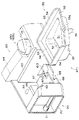
一方、収容凹部60が設けられた下球皿構造体20は、図7に球抜き機構BM1aの分解斜視図を示すように、下球皿構造体20の基体をなすベース体21と、球皿構造体20の外殻をなす外装体22とを主体とし、ベース体21に後述する球抜き機構を組み付け、その前方から外装体22を覆い被せるように係合させて、ベース体21の後面側から外装体22をネジ固定することで一体のアッセンブリに形成される。そして、このように部分組立された下球皿構造体20を前枠下部の取付位置に嵌合位置決めして、前枠2の後面側からベース体21をネジ固定することで、下球皿構造体20が前枠2の下部所定位置に組み付けられる。
On the other hand, the lower ball tray structure 20 provided with the housing recess 60 includes a base body 21 that forms the base of the lower ball tray structure 20 and a ball tray, as shown in an exploded perspective view of the ball removal mechanism BM1a in FIG. The exterior body 22 that forms the outer shell of the structure 20 is a main body, and a ball punching mechanism, which will be described later, is assembled to the base body 21 and engaged so as to cover the exterior body 22 from the front. The exterior body 22 is formed into an integral assembly by screwing. Then, the lower ball tray structure 20 partially assembled in this way is fitted and positioned at the mounting position of the lower part of the front frame, and the base body 21 is fixed by screws from the rear surface side of the front frame 2, thereby lower ball tray structure. The body 20 is assembled at a predetermined position below the front frame 2.
灰皿50を収容保持する収容凹部60は、下球皿構造体20における下球皿23と隣接してその左側に設けられており、外装体22が灰皿50の形状寸法に合わせて正面視凹状に切り欠かれ前面および上面開放の収容室が形成されるとともに、その奥部に灰皿50の後部と係脱自在な収容側後方係合部および灰皿50の下部と係脱自在な収容側下方係合部が設けられて構成される。
The housing recess 60 for housing and holding the ashtray 50 is provided on the left side adjacent to the lower ball tray 23 in the lower ball tray structure 20, and the exterior body 22 has a concave shape in front view according to the shape and dimensions of the ashtray 50. An accommodation chamber which is cut out and has a front surface and an upper surface is formed, and a rear side engaging portion which can be engaged with and disengaged from the rear portion of the ashtray 50 and a lower portion which can be engaged and disengaged from the lower portion of the ashtray 50. A part is provided and configured.
収容凹部60の幅寸法、具体的には外装体22における切り欠き部の左右の壁面間隔は、灰皿50における容体部51,52の外形幅に合わせてわずかに大きめに形成されており、左右の壁面の上方には縁部53および囲壁54の形状寸法に合わせた支持レール部63が形成されている。収容凹部60と下球皿23との間では、外装体22が上方に延出されて一定幅を有する区画壁64が形成されており、その突出高さは下球皿23の開口上面および灰皿装着時における容体部51,52の開口上面よりも高く、後方に向けて徐々に高くなる傾斜壁に形成されている。
The width dimension of the housing recess 60, specifically, the space between the left and right wall surfaces of the cutout portion of the exterior body 22 is formed slightly larger to match the outer width of the container portions 51 and 52 in the ashtray 50. Above the wall surface, a support rail portion 63 is formed in accordance with the shape and dimensions of the edge portion 53 and the surrounding wall 54. Between the housing recess 60 and the lower ball tray 23, the exterior body 22 is extended upward to form a partition wall 64 having a certain width, and the protruding height thereof is the upper surface of the opening of the lower ball tray 23 and the ashtray. It is formed in the inclined wall which is higher than the opening upper surface of the container parts 51 and 52 at the time of mounting | wearing, and becomes high gradually toward back.
収容凹部60の下側では、外装体22の周囲の底面と同一面上に底面カバー68が形成されいる。底面カバー68はその前縁が収容凹部60における左側の壁面の前端位置に合わせて左右の壁面を繋いで形成され、前縁中央には半円形に切り欠かれた指入れ部69が形成されている。
A bottom cover 68 is formed on the lower side of the housing recess 60 on the same surface as the bottom surface around the exterior body 22. The bottom cover 68 has a front edge formed by connecting the left and right wall surfaces to the front end position of the left wall surface in the housing recess 60, and a finger pocket 69 cut out in a semicircular shape is formed at the center of the front edge. Yes.
一方、収容凹部60の奥部では、ベース体21の立設面が収容凹部60に面して後方壁面を形成し、この後方壁面に灰皿50の後部と係脱自在な収容側後方係合部が設けられている。また後方壁面の下側には底面カバー68の上方に位置して収容凹部60に突出する支持台座67が形成されており、その上面が収容凹部60の収容側下方係合部を構成する。
On the other hand, at the back of the housing recess 60, the standing surface of the base body 21 faces the housing recess 60 to form a rear wall surface, and the housing side rear engagement portion detachably engageable with the rear portion of the ashtray 50 on the rear wall surface. Is provided. A support pedestal 67 that is positioned above the bottom cover 68 and protrudes into the housing recess 60 is formed below the rear wall surface, and its upper surface constitutes a housing-side lower engagement portion of the housing recess 60.
後方壁面に設けられた収容側後方係合部は、前方に突出成型されたテーパピン状の連結ピン65、および連結ピン65の下側に位置して前方に膨出成型された矩形箱状の支持凸部66からなり、連結ピン65が灰皿50の後面に形成されたピン受容穴55と嵌脱自在に、支持凸部66が受容壁56と係脱自在に形成されている。
The housing-side rear engagement portion provided on the rear wall surface is a taper pin-shaped connection pin 65 protruding forward and a rectangular box-shaped support that is located under the connection pin 65 and bulges forward. The protrusion 66 is formed so that the connecting pin 65 is detachable from the pin receiving hole 55 formed on the rear surface of the ashtray 50, and the support protrusion 66 is detachably connected to the receiving wall 56.
支持台座67は、灰皿底面57(吸い殻貯留部52の下面)を支持する台座であり、ピン受容穴55を連結ピン65に嵌合させて灰皿50を収容凹部60に装着したときの灰皿底面57の高さ位置を基準として形成されている。支持台座67の前端側は灰皿底面57の配設位置よりも幾分前方に延びて形成されており、その上面側に灰皿底面の前方R部と位置整合する側面視三角形状の脱落防止突起67s,67sが張出成型されている。また支持台座67の下面側には、脱落防止突起67s,67sの外側に位置して下方に突出し、前後に延びる細畦状のスペーサリブ67r,67rが形成されており、底面カバー68と支持面との間に所定の放熱空間を形成しつつ底面カバー68に安定支持されるようになっている。
The support pedestal 67 is a pedestal that supports the ashtray bottom surface 57 (the lower surface of the butt storage portion 52), and the ashtray bottom surface 57 when the pin receiving hole 55 is fitted to the connecting pin 65 and the ashtray 50 is mounted in the housing recess 60. It is formed on the basis of the height position. The front end side of the support pedestal 67 is formed so as to extend somewhat forward from the position where the ashtray bottom surface 57 is disposed, and the top surface of the support base 67 has a triangular drop-out prevention projection 67s aligned with the front R portion of the ashtray bottom surface. 67s are overmolded. Further, on the lower surface side of the support pedestal 67, narrow rib-like spacer ribs 67r and 67r are formed, which are located outside the drop-off prevention protrusions 67s and 67s and project downward, and extend in the front-rear direction. A predetermined heat radiation space is formed between the two and the bottom cover 68 is stably supported.
このように各部が構成される灰皿構造AT1では、灰皿50の灰皿側後方係合部55,56を収容凹部60の収容側後方係合部65,66に係合させ、灰皿底面57を支持台座67に支持させることで、灰皿50が収容凹部60に着脱自在に装着される。
In the ashtray structure AT1 configured as described above, the ashtray side rear engagement portions 55 and 56 of the ashtray 50 are engaged with the storage side rear engagement portions 65 and 66 of the storage recess 60, and the ashtray bottom surface 57 is supported by the support base. The ashtray 50 is detachably attached to the housing recess 60 by being supported by 67.
灰皿50の装着時には、図4に示すように収容凹部60の前方斜め上方から灰皿50を前傾姿勢で嵌挿し、灰皿50の左右の縁部53を収容凹部60の左右の支持レール部63に支持および案内させて、ピン受容穴55を連結ピン65の先端部に係合させる。このとき、灰皿底面57の前方R部が支持台座67に形成された脱落防止突起67sの傾斜面と係合する。そこで、脱落防止突起67sの傾斜面を滑らせるようにして灰皿50を後方にスライドさせつつ前端側を下方に揺動させる。するとピン受容穴55が連結ピン65を受容して嵌合し、受容壁56が支持凸部66の上面および左右面と係合し、灰皿底面57が支持台座67の支持面と係合し、さらに左右の縁部53および囲壁部54が支持レール部63と係合して灰皿50が収容凹部60に装着される。
When the ashtray 50 is mounted, the ashtray 50 is inserted in a forward tilted posture from the upper front of the housing recess 60 as shown in FIG. 4, and the left and right edge portions 53 of the ashtray 50 are attached to the left and right support rail portions 63 of the housing recess 60. The pin receiving hole 55 is engaged with the distal end portion of the connecting pin 65 by being supported and guided. At this time, the front R portion of the ashtray bottom surface 57 engages with the inclined surface of the drop-off prevention protrusion 67s formed on the support base 67. Therefore, the front end side is swung downward while sliding the ashtray 50 backward so as to slide the inclined surface of the drop-off preventing projection 67s. Then, the pin receiving hole 55 receives and fits the connecting pin 65, the receiving wall 56 engages with the upper surface and the left and right surfaces of the support convex portion 66, the ashtray bottom surface 57 engages with the support surface of the support pedestal 67, Further, the left and right edge portions 53 and the surrounding wall portion 54 are engaged with the support rail portion 63, and the ashtray 50 is mounted in the housing recess 60.
こうして灰皿50が収容凹部60に装着されると、灰皿50は上記各部の係合関係によって位置決め支持され、上下左右方向への移動、連結ピン65を軸とする左右方向の傾動、連結ピン嵌合部近傍を支点とする上下方向の揺動、および水平面内での旋回動が規制され、また後方壁面と脱落防止突起67sとにより前後方向の移動が規制されて、挿抜方向(前方への移動と上方への揺動の組み合わせ)を除く6自由度の変位が規制され収容凹部60に安定的に係止保持される。
When the ashtray 50 is mounted in the housing recess 60 in this way, the ashtray 50 is positioned and supported by the engagement relationship of the above parts, moved in the vertical and horizontal directions, tilted in the horizontal direction about the connecting pin 65, and connected pin fitting. Oscillation in the vertical direction around the fulcrum and swivel movement in the horizontal plane are restricted, and movement in the front-rear direction is restricted by the rear wall surface and the drop-off prevention projection 67s, and the insertion / removal direction (forward movement and The displacement of 6 degrees of freedom (except for the combination of upward swinging) is regulated and is stably held and held in the housing recess 60.
灰皿50が装着された状態では、下球皿23と灰皿50との間に下球皿23の開口上面および容体部51,52の開口上面よりも高く延出された区画壁64が存在しており、下球皿23と灰皿50との間で遊技球や灰が行き来し難い構成になっている。このため、例えば遊技者が下球皿23に貯留された遊技球をすくい上げようとして下球皿23から遊技球が溢れても、溢れ出た遊技球が区画壁64に阻止されて灰皿50側に転落することがなく、また灰皿50に仮置きしたタバコが転動して下球皿23に転落したり、容体部51,52に収容されたタバコの灰がもみ消し時に溢れて下球皿23に混入し遊技球が灰まみれになるようなこともない。さらに、この区画壁64が一定幅を有して前方に下傾して形成されているため、万が一遊技球が区画壁64の上面に乗った場合であっても前方に導かれて灰皿50側に転落しにくい構成になっている。
In a state where the ashtray 50 is mounted, a partition wall 64 extending higher than the upper opening surface of the lower ball tray 23 and the upper opening surfaces of the container parts 51 and 52 exists between the lower ball tray 23 and the ashtray 50. The game ball and the ash are difficult to travel between the lower ball tray 23 and the ashtray 50. For this reason, for example, even if a player tries to scoop up the game balls stored in the lower ball tray 23 and overflows from the lower ball tray 23, the overflowing game balls are blocked by the partition wall 64 and moved to the ashtray 50 side. The cigarette temporarily placed in the ashtray 50 rolls and falls to the lower ball tray 23, or the ash of the cigarettes accommodated in the container portions 51 and 52 overflows and disappears into the lower ball tray 23. There is no such thing as a mixed game ball covered with ash. Further, since the partition wall 64 has a certain width and is tilted downward, even if the game ball rides on the upper surface of the partition wall 64, the partition wall 64 is guided forward and the ashtray 50 side. It has a structure that is difficult to fall down.
また灰皿構造AT1では、底面カバー68および支持台座67を短く形成し、もみ消し部51の下面側が開放状態になるように構成している。このため、灰皿50の各部のうちで最も高温になる頻度が高いもみ消し部51の放熱性が良好であり、仮置きされたタバコの火やもみ消されたタバコの火種による過熱を防止して灰皿50の損傷を抑えることができる。また吸い殻貯留部52の下面(灰皿底面57)を支持する支持台座67には、スペーサーリブ67rを設けてすのこ状に形成し、底面カバー68と支持台座67との間に放熱空間を形成している。このため、灰皿底面57から伝達される熱が蓄熱されるようなことがなく、一般的に熱可塑性樹脂材料を用いて一体成型されるベース体21の熱変形や劣化を抑制することができる。
In the ashtray structure AT1, the bottom cover 68 and the support pedestal 67 are formed short so that the lower surface side of the frosted portion 51 is open. For this reason, the heat dissipation of the frosted portion 51, which has the highest frequency among the portions of the ashtray 50, is good and prevents overheating due to the fire of the temporarily placed cigarette and the fired type of the smoked cigarette. 50 damage can be suppressed. The support pedestal 67 that supports the lower surface (the ashtray bottom surface 57) of the butt butt storage 52 is provided with spacer ribs 67r to form a saw-like shape, and a heat radiation space is formed between the bottom cover 68 and the support pedestal 67. Yes. For this reason, heat transmitted from the ashtray bottom surface 57 is not stored, and thermal deformation and deterioration of the base body 21 that is generally integrally molded using a thermoplastic resin material can be suppressed.
一方、装着された灰皿50を取り外すときには、底面カバー68に切り欠き形成された指入れ部69に指を差し入れ、もみ消し部下面の指掛け部59に指を掛けて手前に引き上げ、灰皿50を前方にスライドさせつつ前端側を上方に揺動させる。すると灰皿底面57の前端R部が脱落防止突起67sの傾斜面を乗り越えるように滑り、ピン受容穴55と連結ピン65との嵌合、受容壁56と支持凸部66との係合、および灰皿底面57と支持台座67との係合が解除される。そこで、灰皿50を水平前方〜上方に引き出すことで灰皿50が収容凹部60から取り外される。
On the other hand, when the mounted ashtray 50 is removed, a finger is inserted into the finger slot 69 formed in the bottom cover 68 and a finger is placed on the finger hook 59 on the lower surface of the buffing portion, and the ashtray 50 is moved forward. The front end side is swung upward while sliding. Then, the front end R portion of the ashtray bottom surface 57 slides over the inclined surface of the drop-off preventing projection 67s, the pin receiving hole 55 and the connecting pin 65 are fitted, the receiving wall 56 and the support convex portion 66 are engaged, and the ashtray. The engagement between the bottom surface 57 and the support base 67 is released. Therefore, the ashtray 50 is removed from the housing recess 60 by pulling out the ashtray 50 from the horizontal front side to the upper side.
このため、遊技施設の係員が灰皿50の着脱を容易に行うことができる。灰皿50は下球皿23と隣接する球皿構造体20の正面左側に設けられており、遊技施設の係員は遊技者の遊技を妨げることなく灰皿50を脱着し、遊技者の後方で吸い殻をバケツ等に回収できる。従って、従来の回動形態の灰皿のように、回収操作を誤って吸い殻や灰を周辺にまき散らしてしまうようなことがなく、さらに灰皿50を脱着するときの灰皿の傾き角が5度程度と小さいため、収容された吸い殻が灰皿後方にこぼれ落ちる心配もない。
For this reason, the attendant of the game facility can easily attach and detach the ashtray 50. The ashtray 50 is provided on the left side of the front of the ball tray structure 20 adjacent to the lower ball tray 23, and an attendant of the game facility removes the ashtray 50 without interfering with the player's game, and puts the butts behind the player. Can be collected in a bucket or the like. Therefore, unlike the conventional ashtray of the rotating form, the collection operation does not accidentally sprinkle butts and ash around the periphery, and the inclination angle of the ashtray when attaching and detaching the ashtray 50 is about 5 degrees. Because it is small, there is no worry that the contained butts will spill behind the ashtray.
また、日常の点検や盤面交換等において、灰皿50の汚れがひどいような場合には灰皿50を取り外して丸洗い洗浄することができ、損傷を受けているような場合には灰皿50を簡単に交換することができる。従って、以上説明した灰皿構造AT1によれば、従来課題とされた種々の問題を解決することができ、このような灰皿構造を備えることにより、遊技者および遊技施設の双方にとって取り扱いが容易で快適な遊技環境を提供することができる。
In addition, when the ashtray 50 is very dirty during daily inspections or panel replacement, the ashtray 50 can be removed and washed, and if it is damaged, the ashtray 50 can be easily replaced. can do. Therefore, according to the ashtray structure AT1 described above, it is possible to solve various problems that have been regarded as conventional problems. By providing such an ashtray structure, the handling is easy and comfortable for both the player and the game facility. A game environment can be provided.
なお、灰皿構造AT1では、連結ピン65および単純揺動による脱落を規制する支持凸部66を収容凹部60側に設け、連結ピン65と嵌合するピン受容穴55および支持凸部66と係合する受容壁56を灰皿50側に設けた例を示したが、これら各部の配設位置は灰皿50側と収容凹部60側とを逆に構成してもよく、また連結ピン65や支持台座67を金属製としてもよい。
In the ashtray structure AT1, the connection pin 65 and the support convex portion 66 that restricts dropping due to simple swinging are provided on the housing recess 60 side, and the pin receiving hole 55 and the support convex portion 66 that engage with the connection pin 65 are engaged. Although the example which provided the receiving wall 56 to the ashtray 50 side was shown, the arrangement | positioning position of these parts may comprise the ashtray 50 side and the accommodation recessed part 60 side reversely, and the connection pin 65 and the support base 67 may be comprised. May be made of metal.
(灰皿構造AT2)
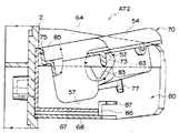
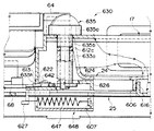
次に、第2構成形態の灰皿構造AT2を、図3および図4に対応した側断面図として図5および図6に示しており、この両図を参照して灰皿構造AT2について説明する。なお灰皿構造AT2は、大別的には灰皿70と収容凹部80とからなり、両者の係合部を除く全体構成は、前述した灰皿50と主要凹部60とからなる第1構成形態の灰皿構造AT1と同様である。そこで、灰皿構造AT1と同様部分に同一番号を付して重複説明を省略し、灰皿70および収容凹部80の係合部の構成を中心に説明する。
(Ashtray structure AT2)
Next, the ashtray structure AT2 of the second configuration form is shown in FIGS. 5 and 6 as side sectional views corresponding to FIGS. 3 and 4, and the ashtray structure AT2 will be described with reference to both drawings. The ashtray structure AT2 is roughly composed of an ashtray 70 and a housing recess 80, and the entire configuration excluding the engaging portion of both is the ashtray structure of the first configuration form consisting of the ashtray 50 and the main recess 60 described above. The same as AT1. Therefore, the same parts as those in the ashtray structure AT1 are denoted by the same reference numerals and redundant description is omitted, and the configuration of the engaging portions of the ashtray 70 and the housing recess 80 will be mainly described.
灰皿70の容体部は、前方が浅く後方に向けて緩やかに深くなるもみ消し部51と、もみ消し部51の後方に一段深く形成された吸い殻貯留部52との2段構成になっており、その上部には額縁状の縁部53が形成され、後方および左右の縁部には容体部51,52の周囲を取り囲む囲壁部54が立設されている。左右の縁部には下方に突出してガイド突起73が形成されている。
The container portion of the ashtray 70 has a two-stage configuration of a mash portion 51 that is shallow at the front and gently deeper toward the rear, and a butts storage portion 52 that is formed one step deep behind the mash portion 51, and an upper portion thereof. A frame-shaped edge 53 is formed on the rear, and a surrounding wall 54 surrounding the container parts 51 and 52 is provided upright at the rear and left and right edges. Guide protrusions 73 are formed on the left and right edges so as to protrude downward.
灰皿70の後部には、囲壁部54の上端中央部が一部切り欠かれて凹状の掛止溝75が形成されている。また灰皿70の下面側では、吸い殻貯留部52の下面により平坦な灰皿底面57が形成され、もみ消し部51の下面中央には先端にテーパ面を有する係止ピン77が補強リブとともに突出成型されている。係止ピン77の突出高さは、ピン先端の端面が灰皿底面57と同一平面上に位置するように形成されており、灰皿70を平坦なテーブル面等に載置したときに、係止ピン77が支持脚として機能し灰皿70が前後に傾いたりぐらついたりすることなく安定姿勢で支持されるようになっている。
At the rear part of the ashtray 70, a central portion of the upper end of the surrounding wall portion 54 is partially cut away to form a concave latching groove 75. Further, on the lower surface side of the ashtray 70, a flat bottom surface 57 of the ashtray is formed by the lower surface of the cigarette butt storage portion 52, and a locking pin 77 having a tapered surface at the tip is projected and molded together with the reinforcing rib at the center of the lower surface of the frosted portion 51. Yes. The protruding height of the locking pin 77 is such that the end surface of the pin tip is located on the same plane as the ashtray bottom surface 57, and when the ashtray 70 is placed on a flat table surface or the like, the locking pin 77 77 functions as a support leg, and the ashtray 70 is supported in a stable posture without tilting or wobbling back and forth.
一方、収容凹部80は、外装体22が灰皿70の形状寸法に合わせて正面視凹状に切り欠かれ前面および上面開放の収容室が形成されるとともに、その奥部に灰皿70の後部と係脱自在な収容側後方係合部および灰皿70の下部と係脱自在な収容側下方係合部が設けられて構成される。
On the other hand, the housing recess 80 is formed so that the exterior body 22 is cut out in a concave shape in front view in accordance with the shape and size of the ashtray 70 to form a housing chamber with a front surface and an open top surface. An accommodation side rear engagement part and a lower part of the ashtray 70 are provided, and an accommodation side lower engagement part that is detachable is provided.
収容凹部80の左右の壁面間隔は、灰皿70の容体部51,52の外形幅よりもわずかに大きめに形成されるとともに、左右の壁面の上方に縁部53および囲壁54の形状寸法に合わせた支持レール部63が形成され、この左右の支持レール部63に灰皿側のガイド突起73と係脱自在に係合して灰皿50の装着を案内するV字状のガイド溝83が形成されている。収容凹部80と下球皿23との間には前述同様の区画壁64が設けられており、その突出高さは下球皿23の開口上面および灰皿装着時における容体部51,52の開口上面よりも高く形成されている。
The space between the left and right wall surfaces of the housing recess 80 is formed to be slightly larger than the outer width of the container portions 51 and 52 of the ashtray 70 and is adjusted to the shape dimensions of the edge 53 and the surrounding wall 54 above the left and right wall surfaces. Support rail portions 63 are formed, and left and right support rail portions 63 are formed with V-shaped guide grooves 83 that guide the mounting of the ashtray 50 by detachably engaging with the guide projections 73 on the ashtray side. . A partition wall 64 similar to that described above is provided between the housing recess 80 and the lower ball tray 23, and the protruding height thereof is the upper surface of the lower ball tray 23 and the upper surfaces of the container portions 51 and 52 when the ashtray is mounted. It is formed higher than.
収容凹部80の奥部では、ベース体21の立設面が収容凹部80に面して後方壁面を形成し、この後方壁面の上端中央部に灰皿70の掛止溝75と係脱自在な掛止突起85が形成されている。なお、掛止突起85および掛止溝75の係合端部は、ともに側断面視円弧状に形成されており、滑らかに係脱し得るようになっている。後方壁面の下側には収容凹部80に突出する支持台座67が形成され、灰皿底面57を支持し得るようになっている。
In the inner part of the housing recess 80, the standing surface of the base body 21 faces the housing recess 80 to form a rear wall surface, and the latching groove 75 of the ashtray 70 is detachably hooked at the center of the upper end of the rear wall surface. A stop projection 85 is formed. The engaging end portions of the latching protrusion 85 and the latching groove 75 are both formed in an arc shape when viewed from the side cross section, and can be smoothly engaged and disengaged. A support pedestal 67 that projects into the housing recess 80 is formed below the rear wall surface so that the ashtray bottom surface 57 can be supported.
収容凹部80の下側では、外装体22の周囲の底面と同一面上に底面カバー68が形成されている。底面カバー68はその前縁が収容凹部80における左側の壁面の前端位置に合わせて左右の壁面を繋いで形成され、前端側中央部には上方に突出して前方に延びるクランク状の収容側下方係合部が設けられている。収容側下方係合部は左右対称に形成された一対のクランプアーム86からなり、基端部から切り離された左右のクランプアーム86が中央の溝を挟んで左右に弾性変位可能に形成されるとともに、溝の先端部には灰皿側の係止ピン77を受容して弾性的に挟持し、係止ピン77を係止し得るピン受容部87が形成されている。
A bottom cover 68 is formed below the housing recess 80 on the same plane as the bottom surface around the exterior body 22. The bottom cover 68 has a front edge formed by connecting left and right wall surfaces in accordance with the front end position of the left wall surface in the housing recess 80, and a crank-shaped housing-side lower member extending upward and projecting forward at the center of the front end side. A joint is provided. The accommodation-side lower engaging portion includes a pair of symmetrically formed clamp arms 86, and the left and right clamp arms 86 separated from the base end portion are formed to be elastically displaceable left and right with a central groove therebetween. A pin receiving portion 87 is formed at the front end of the groove to receive the latch pin 77 on the ashtray side and elastically hold it so that the lock pin 77 can be locked.
このように各部が構成される灰皿構造AT2では、灰皿70の掛止溝75を収容凹部80の掛止突起85に係合させ、係止ピン77をピン受容部87に嵌合させることで、灰皿70が収容凹部80に着脱自在に装着される。
In the ashtray structure AT2 in which each part is configured in this manner, by engaging the latching groove 75 of the ashtray 70 with the latching protrusion 85 of the housing recess 80 and fitting the locking pin 77 to the pin receiving part 87, The ashtray 70 is detachably attached to the housing recess 80.
灰皿70の装着時には、図6に示すように収容凹部80の前方斜め上方から灰皿70を前傾姿勢で嵌挿し、灰皿70の左右の縁部53を収容凹部80の左右の支持レール部63に支持および案内させて、掛止溝75を掛止突起85に係合させる。そして係止溝75と掛止突起85の係合部を支点にして灰皿70の前端側を下方に揺動させ、ガイド突起73をガイド溝83に沿って滑らせるように沈み込ませる。
When the ashtray 70 is mounted, the ashtray 70 is fitted in a forward tilted posture from the upper front side of the housing recess 80 as shown in FIG. 6, and the left and right edge portions 53 of the ashtray 70 are attached to the left and right support rail portions 63 of the housing recess 80. The latch groove 75 is engaged with the latch protrusion 85 by being supported and guided. Then, the front end side of the ashtray 70 is swung downward with the engaging portion of the locking groove 75 and the latching protrusion 85 as a fulcrum, and the guide protrusion 73 is slid so as to slide along the guide groove 83.
すると、係止ピン77の先端に形成されたテーパ面が斜め上方からピン受容部87に進入して係合し、ピン受容部87を押し開くように左右のクランプアーム86を弾性変形させながらピン受容部87に嵌入して、係止ピン77が左右のクランプアーム86に弾性的に挟持された状態で係止される。このとき、灰皿底面57が支持台座67の支持面と係合し、左右の縁部53および囲壁部54が支持レール部63と係合し、ガイド突起73がガイド溝83の底部と係合して灰皿70が収容凹部80に装着される。
Then, the taper surface formed at the tip of the locking pin 77 enters and engages with the pin receiving portion 87 from obliquely above, and the left and right clamp arms 86 are elastically deformed so as to push open the pin receiving portion 87. The locking pin 77 is fitted into the receiving portion 87 and locked in a state of being elastically held between the left and right clamp arms 86. At this time, the ashtray bottom surface 57 is engaged with the support surface of the support pedestal 67, the left and right edge portions 53 and the surrounding wall portion 54 are engaged with the support rail portion 63, and the guide protrusion 73 is engaged with the bottom portion of the guide groove 83. The ashtray 70 is mounted in the housing recess 80.
こうして灰皿70が収容凹部80に装着されると、灰皿70は上記各部の係合関係によって位置決め支持され、上下左右ならびに前後方向への移動、左右方向の傾動、掛止突起85を支点とする上下方向の揺動、および水平面内での旋回動が規制されて、6自由度の変位が規制され収容凹部80に安定的に係止保持される。
When the ashtray 70 is mounted in the housing recess 80 in this manner, the ashtray 70 is positioned and supported by the engagement relationship of the above parts, and is moved up and down, left and right, as well as forward and backward, tilted in the left and right directions, and vertically The swinging of the direction and the turning movement in the horizontal plane are restricted, the displacement of 6 degrees of freedom is restricted, and the holding recess 80 is stably locked and held.
灰皿70が装着された状態では、下球皿23と灰皿70との間に両者の開口上面よりも高く延出された区画壁64が存在しており、下球皿23と灰皿70との間で遊技球や灰が行き来し難い構成になっている。このため、例えば遊技者が下球皿23に貯留された遊技球をすくい上げようとして下球皿23から遊技球が溢れても、溢れ出た遊技球が区画壁64に阻止されて灰皿70側に転落することがなく、また灰皿70に仮置きしたタバコが転動して下球皿23に転落したり、容体部51,52に収容されたタバコの灰がもみ消し時に溢れて下球皿23に混入し遊技球が灰まみれになるようなこともない。さらに、この区画壁64が一定幅を有して前方に下傾して形成されているため、万が一遊技球が区画壁64の上面に乗った場合であっても前方に導かれて灰皿70側に転落しにくい構成になっている。
In the state in which the ashtray 70 is mounted, a partition wall 64 that extends higher than the upper surface of both openings exists between the lower ball tray 23 and the ashtray 70, and between the lower ball tray 23 and the ashtray 70. The game balls and ashes are difficult to come and go. For this reason, for example, even if the player tries to scoop up the game balls stored in the lower ball tray 23 and overflows from the lower ball tray 23, the overflowed game balls are blocked by the partition wall 64 and moved to the ashtray 70 side. The cigarette temporarily placed on the ashtray 70 rolls and falls to the lower ball tray 23, or the ash of the cigarettes accommodated in the container portions 51 and 52 overflows and disappears into the lower ball tray 23. There is no such thing as a mixed game ball covered with ash. Further, since the partition wall 64 has a certain width and is tilted downward, even if the game ball rides on the upper surface of the partition wall 64, the partition wall 64 is guided forward and the ashtray 70 side. It has a structure that is difficult to fall down.
また灰皿構造AT2では、底面カバー68および支持台座67を短く形成し、もみ消し部51の下面側が開放状態になるように構成している。このため、灰皿70の各部のうちで最も高温になる頻度が高いもみ消し部51の放熱性が良好であり、仮置きされたタバコの火やもみ消されたタバコの火種による過熱を防止して灰皿70の損傷を抑えることができる。また吸い殻貯留部52の下面を支持する支持台座67には、スペーサーリブ67rを設けてすのこ状に形成し、底面カバー68と支持台座67との間に放熱空間を形成している。このため、灰皿底面57から伝達される熱が蓄熱されるようなことなく、ベース体21の熱変形や劣化を抑制することができる。
In the ashtray structure AT2, the bottom cover 68 and the support pedestal 67 are formed short so that the lower surface side of the frosted portion 51 is open. For this reason, the heat dissipation property of the frosted portion 51, which has the highest frequency among the portions of the ashtray 70, is good, and the ashtray is prevented from overheating due to the fire of the temporarily placed cigarette and the fired type of the smoked tobacco. 70 damage can be suppressed. The support pedestal 67 that supports the lower surface of the cigarette butt storage portion 52 is provided with spacer ribs 67r to form a saw-like shape, and a heat radiation space is formed between the bottom cover 68 and the support pedestal 67. For this reason, thermal deformation and deterioration of the base body 21 can be suppressed without the heat transmitted from the ashtray bottom surface 57 being stored.
一方、装着された灰皿70を取り外すときには、係止ピン77の下端面またはもみ消し部51の下面に指を掛けて手前に引き上げ、掛止溝75と掛止突起85との係合部を支点にして灰皿70の前端側を上方に揺動させる。するとピン受容部87に弾性的に挟持されていた係止ピン77が外れて係止が解除され、ガイド突起73がガイド溝83の傾斜面を滑るように上動して各部の係合が解除される。そこで、灰皿70を水平前方〜上方に引き出すことで灰皿70が収容凹部80から取り外される。
On the other hand, when removing the mounted ashtray 70, a finger is placed on the lower end surface of the locking pin 77 or the lower surface of the eraser 51 and pulled up, and the engaging portion of the latching groove 75 and the latching projection 85 is used as a fulcrum. Then, the front end side of the ashtray 70 is swung upward. Then, the locking pin 77 elastically clamped by the pin receiving portion 87 is released and the locking is released, and the guide projection 73 moves upward so as to slide on the inclined surface of the guide groove 83, and the engagement of each portion is released. Is done. Therefore, the ashtray 70 is removed from the housing recess 80 by pulling out the ashtray 70 from the horizontal front side to the upper side.
このため、遊技施設の係員が灰皿70の着脱を容易に行うことができる。灰皿70は球皿構造体20の正面左側に設けられており、遊技施設の係員は遊技者の遊技を妨げることなく灰皿70を脱着し、遊技者の後方で吸い殻をバケツ等に回収できる。従って、従来の回動形態の灰皿のように、回収操作を誤って吸い殻や灰を周辺にまき散らしてしまうようなことがない。また、日常の点検や盤面交換等において、灰皿70の汚れがひどいような場合には灰皿70を取り外して丸洗い洗浄することができ、損傷を受けているような場合には灰皿70を簡単に交換することができる。従って、以上説明した灰皿構造AT2においても、従来課題とされた種々の問題を解決することができ、このような灰皿構造を備えることにより、遊技者および遊技施設の双方にとって取り扱いが容易で快適な遊技環境を提供することができる。
For this reason, the attendant of the game facility can easily attach and detach the ashtray 70. The ashtray 70 is provided on the left side of the front surface of the ball tray structure 20, and a clerk of the game facility can remove and remove the ashtray 70 without interfering with the player's game, and collect the butts in a bucket or the like behind the player. Therefore, unlike a conventional rotating ashtray, the collection operation does not accidentally sprinkle butts and ash around. In addition, when the ashtray 70 is very dirty during daily inspections or panel replacement, the ashtray 70 can be removed and washed and washed. If the ashtray 70 is damaged, the ashtray 70 can be easily replaced. can do. Accordingly, the above-described ashtray structure AT2 can also solve various problems that have been regarded as conventional problems, and by providing such an ashtray structure, it is easy to handle and comfortable for both players and amusement facilities. A gaming environment can be provided.
なお、灰皿構造AT2では、掛止溝75および係止ピン77を灰皿70側に設け、掛止溝と係合する掛止突起85および係止ピンを受容して係止するピン受容部87を収容凹部80側に設けた例を示したが、これら各部の配設位置は灰皿70側と収容凹部80側とを逆に構成してもよく、また掛止溝75を形成することなく掛止突起85が囲壁54の上端部と係合するように構成してもよい。
In the ashtray structure AT2, the latching groove 75 and the latching pin 77 are provided on the ashtray 70 side, and the latching projection 85 and the latching pin that engage with the latching groove are received and latched. Although the example provided in the accommodation recessed part 80 side was shown, as for the arrangement position of these parts, the ashtray 70 side and the accommodation recessed part 80 side may be comprised reversely, and it latches without forming the latching groove 75 The protrusion 85 may be configured to engage with the upper end portion of the surrounding wall 54.
さて、以上説明した灰皿構造AT(AT1またはAT2)と隣接して、下球皿23に貯留された遊技球を下球皿構造体20の下方に準備した球箱BBに落下させて収容させる球抜き機構BMが設けられている。発明者は頭書記載の課題を解決して目的を達成するため種々の構成形態の球抜き機構BMを考案しており、以降、各構成形態の球抜き機構BM1〜BM6について順に説明する。
Now, adjacent to the above-described ashtray structure AT (AT1 or AT2), the game balls stored in the lower ball tray 23 are dropped into the ball box BB prepared below the lower ball tray structure 20 to be stored. A punching mechanism BM is provided. The inventor has devised various ball configuration mechanisms BM in order to solve the problems described in the headline and achieve the object. Hereinafter, the ball configuration mechanisms BM1 to BM6 of each configuration mode will be described in order.
第1構成形態の球抜き機構BM1は、底部に球抜き口24を有し上方に開口する皿部内に遊技球を貯留する下球皿23と、球抜き口24の背面側に水平変位可能に配設され球抜き口24を開閉する弁体120と、弁体120の変位操作を行う操作部材130を備え、操作部材130の操作部135が下球皿23の左側における下球皿構造体20の上面側に前後方向にスライド操作可能に設けられて、操作部135をスライド操作したときに弁体120が水平変位して球抜き口24を開閉するように構成される。
The ball removing mechanism BM1 of the first configuration form has a ball outlet 24 at the bottom and a lower ball tray 23 for storing game balls in a dish portion opened upward, and can be horizontally displaced on the back side of the ball outlet 24. A valve body 120 that opens and closes the ball outlet 24 and an operation member 130 that performs a displacement operation of the valve body 120 are provided, and the operation unit 135 of the operation member 130 has a lower ball dish structure 20 on the left side of the lower ball dish 23. The valve body 120 is horizontally displaced to open and close the ball outlet 24 when the operation unit 135 is slid.
(球抜き機構BM1a)
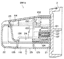
本構成形態における第1構成例の球抜き機構BM1aを図7〜図13に示しており、以下これらの各図を参照して球抜き機構BM1aについて説明する。ここで、各図について予め簡潔に説明すると、図7は球抜き機構BM1aの構成各部を斜め後方から見た分解斜視図、図8は球抜き機構BM1aにおける弁体120を主として示す斜め前方から見た斜視図、図9は球抜き機構BM1aを正面側から見た断面図、図10は球抜き機構BM1aを背面側から見た断面図、図11は球抜き機構BM1aの平面図、図12は球抜き機構BM1aを下球皿23側から見た側断面図、図13は球抜き機構BM1aにより球抜き口を開放した状態の側断面図である。
(Ball removal mechanism BM1a)
The ball removal mechanism BM1a of the first configuration example in the present configuration is shown in FIGS. 7 to 13, and the ball removal mechanism BM1a will be described below with reference to these drawings. Here, each figure will be described briefly in advance. FIG. 7 is an exploded perspective view of the components of the ball removal mechanism BM1a as viewed obliquely from the rear, and FIG. 9 is a sectional view of the ball removal mechanism BM1a as viewed from the front side, FIG. 10 is a sectional view of the ball removal mechanism BM1a as viewed from the back side, FIG. 11 is a plan view of the ball removal mechanism BM1a, and FIG. FIG. 13 is a side sectional view of the ball removal mechanism BM1a as viewed from the lower ball dish 23 side, and FIG. 13 is a side sectional view of the ball removal mechanism BM1a with the ball removal opening opened.
下球皿構造体20は、図7を参照して既述したように、下球皿構造体20の基体をなすベース体21と、下球皿構造体20の外殻をなす外装体22とを主体とし、ベース体21の前方から外装体22を覆い被せるように係合させて、ベース体21の後面側から外装体22をネジ固定することで一体のアッセンブリに形成される。
As described above with reference to FIG. 7, the lower ball dish structure 20 includes the base body 21 that forms the base of the lower ball dish structure 20, and the exterior body 22 that forms the outer shell of the lower ball dish structure 20. , The outer body 22 is engaged from the front of the base body 21 and the outer body 22 is screwed from the rear surface side of the base body 21 to form an integrated assembly.
ベース体21には、底面が緩く前方および左方(灰皿構造側)に下傾して上面開放の深皿形態をなす下球皿23が一体に成型され、傾斜下端の左前方部に、底面から左側壁にかけて上下連通する球抜き口24が開口形成されている。
The base body 21 is integrally formed with a lower ball tray 23 that is loose and has a bottom surface that is inclined forward and to the left (ashtray structure side) to form a deep dish with an open top surface. A ball outlet 24 that communicates vertically with the left side wall is formed.
下球皿23の左上方には外装体22に形成された区画壁64の内側形状と整合して前後方向に係脱自在な区画壁係合部101が設けられるとともに、この区画壁係合部101の一部が切り欠かれて操作部材130の可動範囲を閉鎖位置と開放位置の間に規定するスライド範囲規制部102が形成され、その下部に上下連通するスリット状のレバー挿通孔103が形成されている。下球皿23の下面側には、球抜き口24の前方に位置して下方に突出する前方転入防止壁105と、球抜き口24の右側方に位置して下方に突出する右側方転入防止壁106とが設けられており、球抜き口24から流下する遊技球が下球皿23の底面と外装体22との間に入り込まないようになっている。
A partition wall engaging portion 101 that is aligned with the inner shape of the partition wall 64 formed on the exterior body 22 and that can be engaged and disengaged in the front-rear direction is provided at the upper left of the lower ball tray 23. 101 is cut out to form a slide range restricting portion 102 that defines the movable range of the operation member 130 between a closed position and an open position, and a slit-like lever insertion hole 103 communicating vertically is formed below the slide range restricting portion 102. Has been. On the lower surface side of the lower ball tray 23, a front transfer prevention wall 105 that is located in front of the ball outlet 24 and protrudes downward, and a right side entry prevention that is located on the right side of the ball outlet 24 and protrudes downward. A wall 106 is provided so that game balls flowing down from the ball outlet 24 do not enter between the bottom surface of the lower ball tray 23 and the outer body 22.
外装体22は、全体として前述した灰皿構造ATの収容凹部60(80)および下球皿23の開口上面を除くベース体21の上下面および前面を覆う外殻カバー状に形成されている。外装体22の底面側には、下球皿側の球抜き口24よりも大きな開口幅を有し、組立状態において球抜き口24の下方に位置して上下連通する放出口25が開口形成されている。区画壁64の下球皿側の側壁には、下球皿23の上縁フランジ面と係合するリブフランジが形成され、その前後中央部にはベース体側のスライド範囲規制部102の形成位置と整合して操作部材130を左右に挿通させるレバー挿通部113が形成されている。
The exterior body 22 is formed in an outer shell cover shape that covers the upper and lower surfaces and the front surface of the base body 21 excluding the housing recess 60 (80) of the ashtray structure AT and the upper opening surface of the lower ball tray 23 as a whole. On the bottom surface side of the outer package 22, there is formed an opening 25 having a larger opening width than the ball outlet 24 on the lower ball tray side and located below the ball outlet 24 in the assembled state and communicating vertically. ing. A rib flange that engages with the upper edge flange surface of the lower ball tray 23 is formed on the side wall of the partition wall 64 on the lower ball tray side. A lever insertion portion 113 that allows the operation member 130 to be inserted to the left and right is formed.
区画壁64の下方では、外装体22の前方壁面および底面から内側に突出してL字フレーム状の左側方転入防止壁116が形成され、その上方に区画壁64の下部領域と下球皿23側とを左右に連通する開口部が形成されている。左側方転入防止壁116の形成位置は放出口25の開口左縁に合わせて形成されており、前方壁面と底面とをL字状に繋いで外装体22の剛性を向上させるとともに、球抜き口24から落下する遊技球を放出口25に案内してベース体21と外装体22との間に遊技球が入り込まないように構成されている。左側方転入防止壁116の左側には、底面から突出して左側方転入防止壁116と平行に前後に延びる断面視T字状のスライドレール112が形成されている。
Below the partition wall 64, an L-shaped left-hand side transfer prevention wall 116 that protrudes inwardly from the front wall surface and bottom surface of the exterior body 22 is formed, and above the lower region of the partition wall 64 and the lower ball tray 23 side. Are formed in the left and right. The formation position of the left side transfer prevention wall 116 is formed in accordance with the left edge of the opening of the discharge port 25, and the rigidity of the exterior body 22 is improved by connecting the front wall surface and the bottom surface in an L shape, and the ball outlet port is formed. The game ball falling from 24 is guided to the discharge port 25 so that the game ball does not enter between the base body 21 and the exterior body 22. Formed on the left side of the left side transfer prevention wall 116 is a T-shaped slide rail 112 that protrudes from the bottom surface and extends in front and rear in parallel with the left side transfer prevention wall 116.
このため、ベース体21の前方から外装体22を覆い被せて係合させると、区画壁64の下方に、収容凹部60の右側壁面、下球皿23の左側壁面、区画壁係合部101、およびスライドレール112に囲まれて、前後に延びる断面視台形状の収容空間(弁体収容部という)111が形成される。弁体収容部111の奥部ではベース体21の立設壁面に、コイルスプリング147の内径よりも幾分小さめの外径を有する円柱状のバネ支柱107が前方に突出して形成されている。また、区画壁64の上面に球抜き機構の操作を説明する案内ラベル118が貼付されている。
For this reason, when the exterior body 22 is covered and engaged from the front of the base body 21, the right wall surface of the housing recess 60, the left wall surface of the lower ball tray 23, the partition wall engaging portion 101, below the partition wall 64, A trapezoidal storage space (referred to as a valve body storage portion) 111 extending in the front-rear direction and surrounded by the slide rail 112 is formed. A columnar spring support column 107 having an outer diameter somewhat smaller than the inner diameter of the coil spring 147 is formed on the standing wall surface of the base body 21 in the inner part of the valve body accommodating portion 111 so as to protrude forward. A guide label 118 is attached to the upper surface of the partition wall 64 to explain the operation of the ball removal mechanism.
一方、弁体120は、前後に延びる中空ブロック状の本体部121と、この本体部121の下部に右側方(球皿側)に延びて形成されたシャッター部124とを主体として構成され、例えばABS樹脂などの熱可塑性樹脂材料を用いて射出成型等の成形手段で一体に成型される。
On the other hand, the valve body 120 is mainly composed of a hollow block-shaped main body part 121 extending in the front-rear direction, and a shutter part 124 formed at the lower part of the main body part 121 so as to extend to the right side (the side of the bowl). It is integrally molded by molding means such as injection molding using a thermoplastic resin material such as ABS resin.
本体部121は、正面視における投影形状が下球皿構造体20における弁体収容部111の断面形状に合わせた台形状に形成されるとともに、本体部121の下面にスライドレール112のレール形状に合わせた凹状のレール係合部122が形成されており、弁体120を弁体収容部111に収容させたときに、レール係合部122がスライドレール112と係合して支持され、本体部121が弁体収容部111の上方および左右の壁面と係合して、前後方向にスライド移動自在に支持されるようになっている。本体部121の上面には、操作部材の嵌合突片133を受容して固定するレバー嵌合孔123が形成され、本体部121の内部中央には、コイルスプリング147の外径よりも幾分大きめの内径を有する円筒状のスプリング収容部127が後方に開いて形成されている。
The main body 121 is formed in a trapezoidal shape in which the projected shape in front view is matched with the cross-sectional shape of the valve body accommodating portion 111 in the lower ball tray structure 20, and the slide rail 112 is formed on the lower surface of the main body 121. A combined concave rail engaging portion 122 is formed, and when the valve body 120 is accommodated in the valve body accommodating portion 111, the rail engaging portion 122 is engaged with and supported by the slide rail 112, and the main body portion 121 is engaged with the upper and left and right wall surfaces of the valve body accommodating portion 111 so as to be slidably supported in the front-rear direction. A lever fitting hole 123 for receiving and fixing the fitting protrusion 133 of the operation member is formed on the upper surface of the main body 121, and the inner center of the main body 121 is somewhat larger than the outer diameter of the coil spring 147. A cylindrical spring accommodating portion 127 having a large inner diameter is formed to open rearward.
シャッター部124は、球抜き口24の下面側の高さ位置に合わせて本体部121の下部から右側方に張り出すプレート状に形成され、その左右方向の張出幅および前後方向寸法が球抜き口24の開口幅および開口寸法よりも幾分大きめに形成されている。一方、球抜き口24は下球皿23の前方に形成され、かつ球抜き口24の開口後縁からベース体21の立設壁面までの寸法がシャッター部124の前後方向寸法よりも大きく設定されている。
The shutter part 124 is formed in a plate shape that protrudes to the right from the lower part of the main body part 121 in accordance with the height position on the lower surface side of the ball outlet 24, and the protruding width in the left-right direction and the dimension in the front-rear direction are the same. It is formed slightly larger than the opening width and opening size of the mouth 24. On the other hand, the ball outlet 24 is formed in front of the lower ball tray 23, and the dimension from the opening rear edge of the ball outlet 24 to the standing wall surface of the base body 21 is set to be larger than the longitudinal dimension of the shutter portion 124. ing.
このため、弁体120を前後にスライドさせたときに、後述する閉鎖位置においてシャッター部124が球抜き口24の開口全体を閉鎖するとともに、開放位置においてシャッター部124がベース体21の立設壁面に当接することなく球抜き口24の開口全体を完全に開放し得るようになっている。なお本構成例では球抜き口24を下球皿23の左側壁まで拡大して開口形成しているため、本体部121の前後方向寸法もシャッター部124の前後方向寸法に合わせて形成している。
For this reason, when the valve body 120 is slid back and forth, the shutter portion 124 closes the entire opening of the ball outlet 24 in a closed position, which will be described later, and the shutter portion 124 stands on the standing wall surface of the base body 21 in the open position. The entire opening of the ball outlet 24 can be completely opened without coming into contact with. In this configuration example, since the ball outlet 24 is enlarged and formed to the left side wall of the lower ball tray 23, the front-rear dimension of the main body 121 is also formed to match the front-rear dimension of the shutter part 124. .
シャッター部124の前端には、下方に延びて後方転入防止壁125が形成されており、シャッター部124を開放したときに球抜き口24から流下する遊技球が下球皿23の底面と外装体22との間に入り込まないようになっている。また本体部121の下部には帯板状の左側方スライド転入防止壁126が前方に突出成型されており、シャッター部124を開放したときに球抜き口24の前方から左側方転入防止壁116を越えて遊技球が弁体収容部111に転入しないように構成されている。
At the front end of the shutter portion 124, a rearward transfer prevention wall 125 is formed extending downward, and the game balls flowing down from the ball outlet 24 when the shutter portion 124 is opened are placed on the bottom surface of the lower ball tray 23 and the exterior body. 22 is not allowed to enter. Further, a strip-like left-side slide-in prevention wall 126 is formed on the lower part of the main body 121 so as to protrude forward. When the shutter part 124 is opened, the left-side inward prevention wall 116 is formed from the front of the ball outlet 24. It is configured so that the game ball does not move into the valve body housing part 111 beyond.
弁体120に固着される操作部材130は、L字アングル状に成型されたレバー部131と、レバー部131の先端側に圧入固定された操作部135とからなる。レバー部の基端側には弁体120の本体部上面に形成されたレバー嵌合孔123に嵌入される嵌合突片133が、レバー部131の先端側には操作部135下端の圧入軸を受容するボス部が形成されている。操作部135の上端は球状に形成され指掛け操作容易になっている。レバー部131および操作部135は、いずれも樹脂材料または金属材料を用いて形成することができ、あるいは両者を一体に成型することも可能であるが、本構成例ではレバー部131に樹脂材料を用い、操作部135に金属材料を用いて量産コストと耐久性とを両立させた構成にしている。
The operation member 130 fixed to the valve body 120 includes a lever part 131 molded in an L-shaped angle shape and an operation part 135 press-fitted and fixed to the distal end side of the lever part 131. On the base end side of the lever portion, a fitting protrusion 133 to be fitted in a lever fitting hole 123 formed on the upper surface of the main body portion of the valve body 120 is provided, and on the distal end side of the lever portion 131 is a press-fit shaft at the lower end of the operation portion 135. A boss portion is formed to receive the. The upper end of the operation unit 135 is formed in a spherical shape so that the finger-hanging operation is easy. Both the lever part 131 and the operation part 135 can be formed using a resin material or a metal material, or both can be integrally molded. In this configuration example, a resin material is used for the lever part 131. Used, a metal material is used for the operation unit 135 to achieve both mass production cost and durability.
このように構成される各部材は、下球皿構造体20の組立工程においてベース体21と外装体22との間に組み付けられ球抜き機構BM1aが形成される。
Each member configured in this manner is assembled between the base body 21 and the exterior body 22 in the assembly process of the lower ball tray structure 20 to form a ball removal mechanism BM1a.
組み付けは、まずベース体21のバネ支柱107にコイルスプリング147の一端を支持させ、前方から弁体120の右側面およびシャッター部124を下球皿23の左側面および下面に沿って支持させて、コイルスプリング147の他端側を弁体背面のスプリング収容部127に収容させる(図8を参照)。これによりコイルスプリング147がベース体側のバネ支柱107と弁体側のスプリング収容部127との間に前後に弾性変移自在に支持される。そこで弁体120を後方に押圧して弁体上面のレバー嵌合孔123をベース体のレバー挿通孔103の下方に位置させ、レバー挿通孔103の上方から操作部材130の嵌合突片133を挿通させて、レバー嵌合孔123に圧入固定する。この際必要に応じて接着剤を用い嵌合突片133をレバー嵌合孔123に固着させてもよい。
For assembly, first, one end of the coil spring 147 is supported by the spring support 107 of the base body 21, and the right side surface of the valve body 120 and the shutter portion 124 are supported along the left side surface and the lower surface of the lower ball dish 23 from the front. The other end side of the coil spring 147 is accommodated in the spring accommodating portion 127 on the back surface of the valve body (see FIG. 8). Thus, the coil spring 147 is supported between the spring support 107 on the base body side and the spring accommodating portion 127 on the valve body so as to be elastically movable back and forth. Therefore, the valve body 120 is pressed rearward so that the lever fitting hole 123 on the upper surface of the valve body is positioned below the lever insertion hole 103 of the base body, and the fitting protrusion 133 of the operation member 130 is inserted from above the lever insertion hole 103. It is inserted and fixed to the lever fitting hole 123 by press-fitting. At this time, the fitting protrusion 133 may be fixed to the lever fitting hole 123 using an adhesive as necessary.
これにより、弁体120が操作部材130とスライド範囲規制部102との係合関係によりベース体21に支持され、バネ支柱107とスプリング収容部147との間に挟持されたコイルスプリング147の付勢力によって操作部材130(レバー部131)の前方側面がスライド範囲規制部102の前端壁面に当接する位置に付勢支持される。
Thus, the urging force of the coil spring 147 is supported by the base body 21 by the engagement relationship between the operation member 130 and the slide range restricting portion 102 and is sandwiched between the spring column 107 and the spring accommodating portion 147. Thus, the front side surface of the operation member 130 (lever portion 131) is urged and supported at a position where it abuts against the front end wall surface of the slide range restricting portion 102.
次いで、ベース体21の前方から外装体22を覆い被せるように装着する。このときベース体の区画壁係合部101が区画壁64と係合して外装体22を左右方向に位置決めし、外装体22を案内するスライドガイドとして機能する。区画壁64の後端部がスライド範囲規制部102の前端位置に達するまで外装体22をスライドさせると、区画壁64のリブフランジがレバー部131に当接する。そこで、区画壁64の右壁面を斜め上方に開くように弾性変形させ、レバー部131を乗り越えさせてレバー挿通部113に導入させる。このとき区画壁64の左側では、弁体120における本体部121の左側面が収容凹部60の右壁面と係合し、弁体のレール係合部122がスライドレール112と係合する。
Next, the exterior body 22 is mounted so as to cover the base body 21 from the front. At this time, the partition wall engaging portion 101 of the base body engages with the partition wall 64 to position the exterior body 22 in the left-right direction and functions as a slide guide for guiding the exterior body 22. When the exterior body 22 is slid until the rear end portion of the partition wall 64 reaches the front end position of the slide range restricting portion 102, the rib flange of the partition wall 64 contacts the lever portion 131. Therefore, the right wall surface of the partition wall 64 is elastically deformed so as to open obliquely upward, and the lever portion 131 is moved over and introduced into the lever insertion portion 113. At this time, on the left side of the partition wall 64, the left side surface of the main body 121 of the valve body 120 is engaged with the right wall surface of the housing recess 60, and the rail engaging portion 122 of the valve body is engaged with the slide rail 112.
そこで、外装体22の後端各部がベース体21の立設壁面に当接するまでスライドさせ、突き当て状態で整合する外装体のネジボスにベース体21の後面側からネジを螺合させて締め込むことで、球抜き機構BM1aが組み付けられ、球抜き機構を備えた下球皿構造体20が形成される。
Then, it slides until each rear-end part of the exterior body 22 contact | abuts to the standing wall surface of the base body 21, and it tightens by screwing a screw from the rear surface side of the base body 21 to the screw boss | hub of the exterior body aligned in abutting state. Thus, the ball removal mechanism BM1a is assembled, and the lower ball dish structure 20 having the ball removal mechanism is formed.
こうして球抜き機構BM1aが組み付けられると、弁体120は区画壁64の下側の弁体収容部111に前後方向に水平変位可能に収容支持され、常にはコイルスプリング147により前方に付勢されて操作部材130がスライド範囲規制部102の前端面に当接する規制位置、具体的には弁体120の本体部121およびシャッター部124が球抜き口24の背面側で開口全体を閉鎖する閉鎖位置に保持される(図12を参照)。従って、下球皿払出通路から払出バケット18および下通出口17を介して下球皿23に払い出された遊技球は、閉鎖位置にある弁体120により流下が規制され下球皿23に貯留される。
When the ball removal mechanism BM1a is assembled in this way, the valve body 120 is accommodated and supported in the valve body accommodating portion 111 below the partition wall 64 so as to be horizontally displaceable in the front-rear direction, and is always urged forward by the coil spring 147. A restriction position where the operation member 130 contacts the front end surface of the slide range restriction portion 102, specifically, a closed position where the main body portion 121 and the shutter portion 124 of the valve body 120 close the entire opening on the back side of the ball outlet 24. Held (see FIG. 12). Accordingly, the game balls discharged from the lower ball tray discharge passage through the discharge bucket 18 and the lower outlet 17 to the lower ball tray 23 are restricted in flow by the valve body 120 in the closed position and stored in the lower ball tray 23. Is done.
球抜き作業を行うには、操作部材130の操作部135をコイルスプリング147の付勢力に抗して後方に押圧する。すると弁体120が弁体収容部111内で後方にスライド移動し、本体部121およびシャッター部124が後方に移動して球抜き口24が開かれる(図11を参照)。そして操作部材130がスライド範囲規制部102の後端面に当接する規制位置まで押圧操作されると、弁体120の本体部121およびシャッター部124が球抜き口24の開口全体を開放する開放位置に配設される(図13を参照)。従って、下球皿23に貯留された遊技球が球抜き口24および放出口25を通って下方に準備された球箱BBに流下する。
In order to perform the ball removal operation, the operation portion 135 of the operation member 130 is pressed backward against the urging force of the coil spring 147. Then, the valve body 120 slides backward in the valve body accommodating portion 111, the main body portion 121 and the shutter portion 124 move rearward, and the ball outlet 24 is opened (see FIG. 11). When the operating member 130 is pressed to the restricting position abutting the rear end surface of the sliding range restriction unit 102, in the open position the main body portion 121 and the shutter 124 of the valve body 120 opens the entire opening of the sphere vent port 24 Disposed (see FIG. 13). Accordingly, the game balls stored in the lower ball tray 23 flow down to the ball box BB prepared below through the ball outlet 24 and the discharge port 25.
ここで、球抜き口24の下側では、球抜き口24の前方に前方転入防止壁105、右側方に右側方転入防止壁106、左側方に左側方転入防止壁116、シャッター部124の前端に後方転入防止壁125が配設され、さらに本体部121の前方に左側方スライド転入防止壁126が配設される。このため、弁体120を開いたときに、球抜き口24の下部周辺がこれらの転入防止壁に囲まれてダクト状の排出路を形成し、球抜き口24から放出口25に流下する遊技球がベース体21と外装体22との間に入り込むようなことがない。
Here, on the lower side of the ball outlet 24, the front entrance prevention wall 105 is located in front of the ball exit 24, the right side entrance prevention wall 106 is located on the right side, the left side entrance prevention wall 116 is located on the left side, and the front end of the shutter portion 124. Further, a rearward transfer prevention wall 125 is provided, and a left-side slide transfer prevention wall 126 is provided in front of the main body 121. For this reason, when the valve body 120 is opened, the lower periphery of the ball outlet 24 is surrounded by these transfer-in prevention walls to form a duct-shaped discharge path, and the game flows down from the ball outlet 24 to the discharge port 25. A sphere does not enter between the base body 21 and the exterior body 22.
また、球抜き機構BM1aでは、コイルスプリング147の内周を支持するバネ支柱107とコイルスプリング147の外周を支持するスプリング収容部127とでコイルスプリング147の前後を支持するとともに、スプリング収容部127を弁体120の本体内部に形成している。このため、弁体120の開放位置において、後方に移動した弁体120の内部(スプリング収容部127の内部)にベース体から前方に突出するバネ支柱107が受容され、コイルスプリング147も略全体が弁体120の内部(同上)に収容される。従って、コンパクトな構成で開口寸法の大きな球抜き機構を構成することができる。
Further, in the ball removal mechanism BM1a, the spring strut 107 that supports the inner periphery of the coil spring 147 and the spring accommodating portion 127 that supports the outer periphery of the coil spring 147 support the front and rear of the coil spring 147, and the spring accommodating portion 127 is It is formed inside the main body of the valve body 120. For this reason, in the open position of the valve body 120, the spring column 107 protruding forward from the base body is received in the valve body 120 moved rearward (inside the spring accommodating portion 127), and the coil spring 147 is also substantially entirely. It is accommodated inside the valve body 120 (same as above). Therefore, it is possible to configure a ball removal mechanism having a large opening size with a compact configuration.
球抜き作業を終了するときには、操作部135を開放位置に保持させる押圧力を弱めればよい。前方への押圧力が弱められると、コイルスプリング147に蓄積された弾性力によってコイルスプリング147が伸長方向に自己復帰し、弁体120が弁体収容部111内を前方にスライド移動して、本体部121およびシャッター部124が球抜き口24を閉じる。そして操作部材130がスライド範囲規制部102の前端面に当接すると弁体120の前方への移動が規制され、所定の付勢力を保持した状態で本体部121およびシャッター部124が球抜き口24の背面側で開口全体を閉鎖する閉鎖位置に保持される(図12を参照)。
When the ball removal operation is finished, the pressing force for holding the operation unit 135 in the open position may be weakened. When the forward pressing force is weakened, the coil spring 147 self-resets in the extending direction by the elastic force accumulated in the coil spring 147, and the valve body 120 slides forward in the valve body housing portion 111, The part 121 and the shutter part 124 close the ball outlet 24. When the operating member 130 comes into contact with the front end surface of the slide range restricting portion 102, the forward movement of the valve body 120 is restricted, and the main body 121 and the shutter portion 124 are held in the ball outlet 24 while maintaining a predetermined urging force. Is held in a closed position that closes the entire opening on the back side (see FIG. 12).
このように、本構成の球抜き機構BM1aでは、球抜き口24の開閉操作を行う操作部135が下球皿23の左側に位置して下球皿構造体20の上面側に前後方向にスライド操作可能に設けられているため、右手で発射ハンドル14を回動操作したまま左手で球抜き操作を簡単に行うことができ、かつ下球皿構造体20と腹部との間隔が密着してしまうような遊技者であっても容易に球抜き操作を行うことができる。
As described above, in the ball removal mechanism BM1a of this configuration, the operation unit 135 for opening and closing the ball removal opening 24 is located on the left side of the lower ball dish 23 and slides in the front-rear direction on the upper surface side of the lower ball dish structure 20. Since it is provided so as to be operable, it is possible to easily perform the ball removing operation with the left hand while rotating the firing handle 14 with the right hand, and the distance between the lower ball tray structure 20 and the abdomen is in close contact. Even such a player can easily perform the ball removal operation.
また、操作部135が下球皿構造体20の上面側に前後方向にスライド操作可能に設けられているため、遊技者が座席から立ち上がったり着座しようとするとき、あるいは隣接するパチンコ機に放置された球箱を取ろうとして横を向いたときなどに、たとえ下球皿構造体20の前面にぶつかっても操作部135が開方向に誤操作されて球抜き口24が開放されるようなことがなく、遊技球を周囲にまき散らしてしまうような事態が生じない。さらに、球抜き機構の主要構成部が区画壁64の下部領域を有効に利用して構成され、操作部135が区画壁64から下球皿23側に突出して配設されるため、コンパクトな構成で操作性の良好な球抜き機構を提供することができる。また、操作部材130を挿通させるレバー挿通部113が区画壁64における下球皿23側の側面に形成されているため、タバコの灰やごみ等が球抜き機構の内部に侵入しにくい構成になっている。
In addition, since the operation unit 135 is provided on the upper surface side of the lower ball tray structure 20 so as to be slidable in the front-rear direction, when the player tries to stand up or sit down from the seat or is left in the adjacent pachinko machine. When the player tries to take a ball box and turns to the side, the operation unit 135 may be erroneously operated in the opening direction even if it hits the front surface of the lower ball tray structure 20, and the ball outlet 24 may be opened. There is no such situation that the game balls are scattered around. Further, the main component of the ball removing mechanism is configured by effectively using the lower region of the partition wall 64, and the operation unit 135 is disposed to protrude from the partition wall 64 toward the lower ball tray 23, so that the compact configuration Thus, it is possible to provide a ball removal mechanism with good operability. Further, since the lever insertion portion 113 through which the operation member 130 is inserted is formed on the side surface of the partition wall 64 on the side of the lower ball tray 23, the structure is such that cigarette ash, dust, and the like do not easily enter the ball removal mechanism. ing.
従って、以上説明した球抜き機構BM1aによれば、誤操作による遊技球の飛散を有効に防止して、遊技者にとって操作性の良好な球抜き機構を提供することができる。
Therefore, according to the ball removal mechanism BM1a described above, it is possible to effectively prevent the game balls from being scattered due to an erroneous operation, and to provide a ball removal mechanism with good operability for the player.
(球抜き機構BM1b)
次に、上述した球抜き機構BM1aと同様に、操作部材を下球皿構造体20の上面左側に前後方向にスライド操作可能に設けた第1構成形態の球抜き機構BM1における第2構成例の球抜き機構BM1bについて、図14〜図16を参照して説明する。ここで、図14は球抜き機構BM1bの構造を斜め前方から見た斜視図、図15は球抜き機構BM1bを正面側から見た断面図、図16は球抜き機構BM1bの平面図である。なお、下球皿構造体20の基本的な構成や灰皿構造AT1などは上述した第1構成例の球抜き機構BM1aと同様であるため、同様部分に同一番号を付して重複説明を省略し、相違する部分を中心に説明する。
(Ball removal mechanism BM1b)
Next, similarly to the above-described ball removal mechanism BM1a, the second configuration example of the ball removal mechanism BM1 of the first configuration form in which the operation member is provided on the upper left side of the lower ball dish structure 20 so as to be slidable in the front-rear direction. The ball removal mechanism BM1b will be described with reference to FIGS. 14 is a perspective view of the structure of the ball removal mechanism BM1b as viewed obliquely from the front, FIG. 15 is a sectional view of the ball removal mechanism BM1b as viewed from the front side, and FIG. 16 is a plan view of the ball removal mechanism BM1b. The basic structure of the lower ball tray structure 20 and the ashtray structure AT1 are the same as the ball removing mechanism BM1a of the first configuration example described above. The description will focus on the differences.
ベース体21における下球皿23の左上方には、外装体22に形成された区画壁64の内側形状と整合して前後方向に係脱自在な区画壁係合部151が設けられ、この区画壁係合部151の右側壁の下部に、左右連通するスリット状のレバー挿通孔153が形成されている。レバー挿通孔153の前後端は閉じており、これにより操作部材180の可動範囲を閉鎖位置と開放位置の間に規定するスライド範囲規制部152を形成する。区画壁係合部151の左側壁にはスライド範囲規制部152の前端位置に対応して左側壁の一部切り欠かれ、操作部材180を左右水平にレバー挿通孔153に挿通させ得るセット凹部154が形成されている。
A partition wall engaging portion 151 that is detachable in the front-rear direction in alignment with the inner shape of the partition wall 64 formed in the exterior body 22 is provided on the upper left side of the lower ball tray 23 in the base body 21. A slit-like lever insertion hole 153 that communicates with the left and right is formed in the lower portion of the right side wall of the wall engaging portion 151. The front and rear ends of the lever insertion hole 153 are closed, thereby forming a slide range restricting portion 152 that defines the movable range of the operation member 180 between the closed position and the open position. The left side wall of the partition wall engaging portion 151 is partially cut away from the left side wall corresponding to the front end position of the slide range restricting portion 152, and the set recess 154 that allows the operation member 180 to be inserted horizontally through the lever insertion hole 153. Is formed.
一方、外装体22側では、区画壁64の右側壁の下部に下球皿23の上縁フランジ面と係合するリブフランジが形成され、ベース体21側のレバー挿通孔153の形成位置と整合して操作部材180を左右に挿通させるレバー挿通部163が形成されている。区画壁64の下方では、外装体22の前方壁面および底面から内側に突出して前後に延びるリブ状のスライドレール162,162が左右に並んで2本平行に形成されている。
On the other hand, on the exterior body 22 side, a rib flange that engages with the upper edge flange surface of the lower ball tray 23 is formed in the lower part of the right side wall of the partition wall 64, and is aligned with the formation position of the lever insertion hole 153 on the base body 21 side. Thus, a lever insertion portion 163 for inserting the operation member 180 to the left and right is formed. Below the partition wall 64, two rib-like slide rails 162, 162 projecting inward from the front wall surface and bottom surface of the exterior body 22 and extending in the front-rear direction are formed side by side in parallel.
これらのスライドレール162は、前方壁面と底面とを繋ぐL字フレーム状に形成されて外装体22の剛性を向上させるとともに、右側のスライドレールは放出口25の開口左縁に合わせて球抜き口24の開口上縁近くまで高く形成されており、球抜き口24から流下する遊技球を放出口25に案内して遊技球がベース体21と外装体22との間に入り込まないようになっている。すなわち本構成例のスライドレール162は、弁体170を前後スライド自在に支持するスライドレールとしての機能のみならず、外装体22の補強フレームとしての機能と、前述した左側方転入防止壁116および左側方スライド転入防止壁126の機能とを兼ね備えた構成になっている。
These slide rails 162 are formed in an L-shaped frame connecting the front wall surface and the bottom surface to improve the rigidity of the exterior body 22, and the right slide rail is aligned with the left edge of the opening of the discharge port 25. 24 is formed so as to be close to the upper edge of the opening, and the game ball flowing down from the ball outlet 24 is guided to the discharge port 25 so that the game ball does not enter between the base body 21 and the exterior body 22. Yes. That is, the slide rail 162 of this configuration example not only functions as a slide rail that supports the valve body 170 so as to be slidable back and forth, but also functions as a reinforcing frame of the exterior body 22, the left-side entry prevention wall 116 and the left side described above. It has the structure which has the function of the direction slide transfer prevention wall 126.
そしてベース体21の前方から外装体22を覆い被せて係合させると、区画壁64の下方に収容凹部60の右側壁面、下球皿23の左側壁面、区画壁係合部151、およびスライドレール162に囲まれて、前後に延びる断面視台形状の弁体収容部161が形成される。
When the exterior body 22 is covered and engaged from the front of the base body 21, the right side wall surface of the housing recess 60, the left side wall surface of the lower ball tray 23, the partition wall engaging portion 151, and the slide rail are provided below the partition wall 64. A valve body accommodating portion 161 having a trapezoidal cross-sectional view extending in the front-rear direction surrounded by 162 is formed.
弁体170は、上記弁体収容部161の断面形状に合わせて形成された中空ブロック状の本体部171と、この本体部171の下部に右側方に延びて形成されたシャッター部174、本体部171の上面から上方に突出して右側方に延びるL字状の操作部材180を主体とし、前述した弁体120と同様の樹脂材料を用いて成型される。球抜き機構BM1bでは、操作部材180を弁体170に一体成型で形成しており、操作部材180の先端に円弧状の操作部185が形成されている。
The valve body 170 includes a hollow block-shaped main body portion 171 formed in accordance with the cross-sectional shape of the valve body housing portion 161, a shutter portion 174 formed to extend to the right side below the main body portion 171, and a main body portion. The L-shaped operation member 180 that protrudes upward from the upper surface of 171 and extends to the right is mainly used, and is molded using the same resin material as the valve body 120 described above. In the ball removal mechanism BM1b, the operation member 180 is formed integrally with the valve body 170, and an arcuate operation portion 185 is formed at the tip of the operation member 180.
本体部171の下面には、左右のスライドレール162,162と係脱自在な凹状のレール係合部172,172が前後に延びて形成され、弁体170を弁体収容部161に収容させたときにレール係合部172がスライドレール162と係合して支持され、本体部171が弁体収容部161の上方および左右の壁面と係合して、前後方向にスライド移動自在に支持されるようになっている。本体部171の内部中央には円筒状のスプリング収容部127が後方に開いて形成されている。
On the lower surface of the main body portion 171, concave rail engaging portions 172 and 172 detachably engageable with the left and right slide rails 162 and 162 are formed extending forward and backward, and the valve body 170 is accommodated in the valve body accommodating portion 161. Sometimes, the rail engaging portion 172 is engaged with and supported by the slide rail 162, and the main body portion 171 is engaged with the upper and left and right wall surfaces of the valve body accommodating portion 161 so as to be slidably supported in the front-rear direction. It is like that. A cylindrical spring accommodating portion 127 is formed at the inner center of the main body portion 171 so as to open rearward.
シャッター部174は、球抜き口24の下面側の高さ位置に合わせて本体部171の下部から右側方に張り出すプレート状に形成され、その左右方向の張出幅および前後方向寸法が球抜き口24の開口幅および開口寸法よりも幾分大きめに形成されている。ここで球抜き口24は下球皿23の前方に形成され、かつ球抜き口24の開口後縁からベース体21の立設壁面までの寸法がシャッター部174の前後方向寸法よりも大きく設定されている。
The shutter portion 174 is formed in a plate shape that protrudes rightward from the lower portion of the main body portion 171 in accordance with the height position of the lower surface side of the ball outlet 24, and has a protruding width in the left-right direction and a dimension in the front-rear direction. It is formed slightly larger than the opening width and opening size of the mouth 24. Here, the ball outlet 24 is formed in front of the lower ball tray 23, and the dimension from the opening rear edge of the ball outlet 24 to the standing wall surface of the base body 21 is set to be larger than the front-rear direction dimension of the shutter portion 174. ing.
このため、弁体170を閉鎖位置に位置させたときにシャッター部174が球抜き口24の開口全体を閉鎖する一方、開放位置においては球抜き口24を完全に開放し得るようになっている。シャッター部174の前端には下方に延びる後方転入防止壁175が形成されており、シャッター部174を開放したときに球抜き口24から流下する遊技球が下球皿23の底面と外装体22との間に入り込まないようになっている。
For this reason, the shutter 174 closes the entire opening of the ball outlet 24 when the valve body 170 is positioned at the closed position, while the ball outlet 24 can be completely opened at the open position. . A rearward transfer prevention wall 175 that extends downward is formed at the front end of the shutter portion 174, and the game balls that flow down from the ball outlet 24 when the shutter portion 174 is opened are located on the bottom surface of the lower ball tray 23, the exterior body 22, and the like. It is supposed not to get in between.
このように構成される各部材がベース体21と外装体22との間に組み付けられ球抜き機構BM1bが形成される。組み付けは、ベース体のバネ支柱107にコイルスプリング147の一端を支持させておき、下球皿23の左側方から操作部180をセット凹部154に位置合わせしてレバー挿通孔153に挿通させ、本体部171の右側面およびシャッター部174を下球皿23の左側面および下面に支持させて、コイルスプリング147の他端側を弁体背面のスプリング収容部127に収容させる。これによりコイルスプリング147がベース体側のバネ支柱107と弁体側のスプリング収容部127との間に前後に弾性変移自在に支持される。
Each member configured in this manner is assembled between the base body 21 and the exterior body 22 to form a ball removal mechanism BM1b. For assembly, the end of the coil spring 147 is supported by the spring support 107 of the base body, and the operation unit 180 is aligned with the set recess 154 from the left side of the lower ball tray 23 and is inserted into the lever insertion hole 153. The right side surface of the portion 171 and the shutter portion 174 are supported on the left side surface and the bottom surface of the lower ball tray 23, and the other end side of the coil spring 147 is accommodated in the spring accommodating portion 127 on the back surface of the valve body. Thus, the coil spring 147 is supported between the spring support 107 on the base body side and the spring accommodating portion 127 on the valve body so as to be elastically movable back and forth.
次いで、ベース体21の前方から外装体22を覆い被せるように装着する。このときベース体の区画壁係合部151が区画壁64と係合して外装体22を左右方向に位置決めし、外装体22を案内するスライドガイドとして機能する。外装体22をガイドに沿ってスライドさせると区画壁64の左側で本体部171の左側面が収容凹部60の右壁面と係合し、レール係合部172がスライドレール162と係合する。さらに外装体22をスライドさせて区画壁64のリブフランジが操作部材180に当接したら、区画壁64の右壁面を斜め上方に開くように弾性変形させ、操作部材180を乗り越えさせてレバー挿通部163に導入させる。そして、外装体22の後端各部がベース体21の立設壁面に当接するまでスライドさせて突き当て、外装体のネジボスにベース体21の後面側からネジを螺合させて締め込むことで、球抜き機構BM1bが組み付けられ、球抜き機構を備えた下球皿構造体20が形成される。
Next, the exterior body 22 is mounted so as to cover the base body 21 from the front. At this time, the partition wall engaging portion 151 of the base body engages with the partition wall 64 to position the exterior body 22 in the left-right direction and functions as a slide guide for guiding the exterior body 22. When the exterior body 22 is slid along the guide, the left side surface of the main body portion 171 engages with the right wall surface of the housing recess 60 on the left side of the partition wall 64, and the rail engagement portion 172 engages with the slide rail 162. When the outer body 22 is further slid and the rib flange of the partition wall 64 abuts on the operation member 180, the right wall surface of the partition wall 64 is elastically deformed so as to open obliquely upward, and the operation member 180 is moved over to move the lever insertion portion. 163. Then, by sliding and abutting until each rear end portion of the exterior body 22 comes into contact with the standing wall surface of the base body 21, a screw is screwed into the screw boss of the exterior body from the rear surface side of the base body 21 and tightened. The ball removal mechanism BM1b is assembled to form the lower ball dish structure 20 having the ball removal mechanism.
球抜き機構BM1bが組み付けられると、弁体170は区画壁64の下側の弁体収容部161に前後方向に水平変位可能に収容支持され、常にはコイルスプリング147により前方に付勢されて操作部材180がスライド範囲規制部152の前端面に当接する規制位置、具体的には弁体170の本体部171およびシャッター部174が球抜き口24の背面側で開口全体を閉鎖する閉鎖位置に保持される(図16を参照)。従って、下球皿23に払い出された遊技球が閉鎖位置にある弁体170により流下規制され下球皿23に貯留される。
When the ball removal mechanism BM1b is assembled, the valve element 170 is accommodated and supported by the valve element accommodating portion 161 below the partition wall 64 so as to be horizontally displaceable in the front-rear direction, and is always urged forward by the coil spring 147 to operate. The restriction position where the member 180 abuts against the front end surface of the slide range restriction portion 152, specifically, the main body portion 171 and the shutter portion 174 of the valve body 170 are held at the closed position where the entire opening is closed on the back side of the ball outlet 24. (See FIG. 16). Accordingly, the game balls paid out to the lower ball tray 23 are regulated to flow down by the valve body 170 in the closed position and stored in the lower ball tray 23.
球抜き作業を行うには、操作部材180の操作部185をコイルスプリング147の付勢力に抗して後方に押圧する。すると弁体170が弁体収容部161内で後方にスライド移動し、本体部171およびシャッター部174が後方に移動して球抜き口24が開かれる。そして操作部材180がスライド範囲規制部152の後端面に当接する規制位置まで押圧操作されると、弁体170の本体部171およびシャッター部174が球抜き口24の開口全体を開放する開放位置に配設される(図16における二点鎖線を参照)。従って、下球皿23に貯留された遊技球が球抜き口24および放出口25を通って下方に準備された球箱BBに流下する。
In order to perform the ball removal operation, the operation portion 185 of the operation member 180 is pressed backward against the urging force of the coil spring 147. Then, the valve body 170 slides backward in the valve body accommodating portion 161, the main body portion 171 and the shutter portion 174 move rearward, and the ball outlet 24 is opened. When the operating member 180 is pressed to the restricting position abutting the rear end surface of the sliding range restricting portion 152, in the open position the body portion 171 and the shutter 174 of the valve body 170 opens the entire opening of the sphere vent port 24 (Refer to the two-dot chain line in FIG. 16). Accordingly, the game balls stored in the lower ball tray 23 flow down to the ball box BB prepared below through the ball outlet 24 and the discharge port 25.
球抜き口24の下側では、球抜き口24の前方に前方転入防止壁105、球抜き口24の右側方に右側方転入防止壁106、球抜き口24の左側方に転入防止壁の機能を有するスライドレール162、シャッター部174の前端に後方転入防止壁175が配設されている。このため、弁体170を開いたときに、球抜き口24の下部周辺がこれらの転入防止壁に囲まれてダクト状の排出路を形成し、球抜き口24から放出口25に流下する遊技球がベース体21と外装体22との間に入り込むようなことがない。
On the lower side of the ball outlet 24, the forward transfer prevention wall 105 is located in front of the ball outlet 24, the right side transfer prevention wall 106 is located on the right side of the ball outlet 24, and the function of the transfer prevention wall is located on the left side of the ball outlet 24. A rear transfer prevention wall 175 is disposed at the front end of the slide rail 162 and the shutter portion 174 having the same. Therefore, when the valve body 170 is opened, the lower periphery of the ball outlet 24 is surrounded by these transfer-in prevention walls to form a duct-like discharge path, and the game flows down from the ball outlet 24 to the discharge port 25. A sphere does not enter between the base body 21 and the exterior body 22.
また、球抜き機構BM1bにおいても、前述した球抜き機構BM1aと同様に、コイルスプリング147の内周を支持するバネ支柱107と外周を支持するスプリング収容部127とでコイルスプリング147を支持し、かつスプリング収容部127を弁体170の本体内部に形成している。このため、弁体170の開放位置において、後方に移動した弁体170(スプリング収容部127)の内部にバネ支柱107が受容され、コイルスプリング147の略全体が弁体170の内部に収容される。従って、コンパクトな構成で開口寸法の大きな球抜き機構を構成することができる。
Also, in the ball removal mechanism BM1b, similarly to the ball removal mechanism BM1a, the coil spring 147 is supported by the spring support column 107 that supports the inner periphery of the coil spring 147 and the spring housing portion 127 that supports the outer periphery, and A spring accommodating portion 127 is formed inside the main body of the valve body 170. For this reason, in the open position of the valve body 170, the spring column 107 is received in the valve body 170 (spring accommodating portion 127) moved rearward, and substantially the entire coil spring 147 is accommodated in the valve body 170. . Therefore, it is possible to configure a ball removal mechanism having a large opening size with a compact configuration.
球抜き作業を終了するときには、操作部185を開放位置に保持させる押圧力を弱めればよい。前方への押圧力が弱められると、コイルスプリング147に蓄積された弾性力によってコイルスプリング147が伸長方向に自己復帰し、弁体170が弁体収容部161内を前方にスライド移動して、本体部171およびシャッター部174が球抜き口24を閉じる。そして操作部材180がスライド範囲規制部152の前端面に当接すると弁体170の前方への移動が規制され、所定の付勢力を保持した状態で本体部171およびシャッター部174が球抜き口24の背面側で開口全体を閉鎖する閉鎖位置に保持される(図12を参照)。
When the ball removal operation is finished, the pressing force for holding the operation unit 185 in the open position may be weakened. When the forward pressing force is weakened, the coil spring 147 self-resets in the extending direction due to the elastic force accumulated in the coil spring 147, and the valve body 170 slides forward in the valve body accommodating portion 161, The part 171 and the shutter part 174 close the ball outlet 24. When the operation member 180 comes into contact with the front end surface of the slide range restricting portion 152, the forward movement of the valve body 170 is restricted, and the main body portion 171 and the shutter portion 174 hold the ball outlet 24 while maintaining a predetermined urging force. Is held in a closed position that closes the entire opening on the back side (see FIG. 12).
このように、本構成の球抜き機構BM1bでは、球抜き口24の開閉操作を行う操作部185が下球皿23の左側に位置して前後方向にスライド操作可能に設けられているため、右手で発射ハンドル14を回動操作したまま左手で球抜き操作を簡単に行うことができ、かつ下球皿構造体20と腹部との間隔が密着してしまうような遊技者であっても容易に球抜き操作を行うことができる。
As described above, in the ball removal mechanism BM1b of the present configuration, the operation unit 185 for opening and closing the ball removal port 24 is provided on the left side of the lower ball tray 23 so as to be slidable in the front-rear direction. The player can easily remove the ball with the left hand while turning the firing handle 14 and can easily be a player who has a close contact between the lower ball tray structure 20 and the abdomen. Ball removal operation can be performed.
また、操作部185が下球皿構造体20の上面側に前後方向にスライド操作可能に設けられているため、遊技者が誤って下球皿構造体20の前面にぶつかっても操作部185が開方向に誤操作されて球抜き口24が開放されるようなことがなく、遊技球を周囲にまき散らしてしまうような事態が生じない。さらに、球抜き機構の主要構成部が区画壁64の下部領域を有効に利用して構成され、操作部185が区画壁64から下球皿23側に突出して配設されるため、コンパクトな構成で操作性の良好な球抜き機構を提供することができる。また、操作部材180を挿通させるレバー挿通部163が区画壁64における下球皿23側の側面に形成されているため、タバコの灰やごみ等が球抜き機構の内部に侵入しにくい構成になっている。
Further, since the operation unit 185 is provided on the upper surface side of the lower ball tray structure 20 so as to be slidable in the front-rear direction, the operation unit 185 can be operated even if the player accidentally hits the front surface of the lower ball tray structure 20. There is no possibility that the ball outlet 24 is opened due to an erroneous operation in the opening direction, and a situation in which game balls are scattered around does not occur. In addition, the main component of the ball removal mechanism is configured by effectively using the lower region of the partition wall 64, and the operation unit 185 is disposed so as to protrude from the partition wall 64 toward the lower ball tray 23. Thus, it is possible to provide a ball removal mechanism with good operability. Further, since the lever insertion portion 163 through which the operation member 180 is inserted is formed on the side surface of the partition wall 64 on the side of the lower ball tray 23, it becomes a configuration in which tobacco ash, dust, and the like do not easily enter the inside of the ball removal mechanism. ing.
従って、以上説明した球抜き機構BM1bによれば、誤操作による遊技球の飛散を有効に防止して、遊技者にとって操作性の良好な球抜き機構を提供することができる。
Therefore, according to the ball removal mechanism BM1b described above, it is possible to effectively prevent scattering of the game ball due to an erroneous operation, and to provide a ball removal mechanism with good operability for the player.
(球抜き機構BM2)
次に、第2構成形態の球抜き機構BM2について、図17〜図27の各図を参照して説明する。ここで、図17は球抜き機構BM2を備えたパチンコ機PMにおけるガラス扉5および上球皿構造体6を開放した状態の正面図(図1に対応する正面図)、図18は灰皿構造AT1を左斜め前方から見た斜視図(図2に対応する斜視図)、図19は灰皿装着状態における灰皿中央部での側断面図(図3に対応する側断面図)、図20は灰皿脱着時における灰皿中央部での側断面図(図4に対応する側断面図)であるが、パチンコ機PMの本体構成および下球皿構造体20に設けられる灰皿構造AT(AT1,AT2)については、既述した内容と同様であるため、図17〜図20の各図における同様部分に同一番号を付して重複説明を省略する。
(Ball removal mechanism BM2)
Next, the ball removal mechanism BM2 of the second configuration form will be described with reference to FIGS. Here, FIG. 17 is a front view (front view corresponding to FIG. 1) of the pachinko machine PM provided with the ball removal mechanism BM2 with the glass door 5 and the upper ball tray structure 6 opened, and FIG. 18 is the ashtray structure AT1. FIG. 19 is a side sectional view (a side sectional view corresponding to FIG. 3) at the center of the ashtray with the ashtray mounted, and FIG. 20 is an ashtray detachment. FIG. 4 is a side sectional view (a side sectional view corresponding to FIG. 4) at the central portion of the ashtray at the time, but regarding the main body configuration of the pachinko machine PM and the ashtray structure AT (AT1, AT2) provided in the lower ball tray structure 20 Since the contents are the same as those already described, the same numbers are assigned to the same parts in each of FIGS.
また、図21は球抜き機構BM2の構造を斜め前方から見た斜視図、図22は球抜き機構BM2における弁体220を主として示す斜め後方から見た斜視図、図23は球抜き機構BM2の組み付け状態を示す平面図、図24は球抜き機構BM2の平面図、図25は球抜き機構BM2を下球皿23側から見た側断面図、図26は球抜き機構BM2を正面側から見た断面図、図27は球抜き機構BM2により球抜き口を開放した状態の側断面図である。
21 is a perspective view of the structure of the ball removal mechanism BM2 as viewed obliquely from the front, FIG. 22 is a perspective view of the ball removal mechanism BM2 as viewed mainly from the rear, showing the valve body 220, and FIG. 23 is a view of the ball removal mechanism BM2. FIG. 24 is a plan view of the ball removal mechanism BM2, FIG. 25 is a side sectional view of the ball removal mechanism BM2 as seen from the lower ball dish 23 side, and FIG. 26 is a view of the ball removal mechanism BM2 from the front side. FIG. 27 is a side sectional view showing a state where the ball outlet is opened by the ball removing mechanism BM2.
球抜き機構BM2は下球皿構造体20に設けられており、底部に球抜き口24を有し上方に開口する皿部内に遊技球を貯留する下球皿23と、球抜き口の背面側に水平変位可能に配設され球抜き口24を開閉する弁体220と、弁体220の変位操作を行う操作部材230とを備え、操作部材230の操作部235が下球皿23の左側における下球皿構造体20の底面側に前後方向にスライド操作可能に設けられ、操作部235をスライド操作したときに弁体220が水平変位して球抜き口24を開閉するように構成される。
The ball removal mechanism BM2 is provided in the lower ball dish structure 20, and includes a lower ball dish 23 for storing game balls in a dish portion having a ball removal opening 24 at the bottom and opening upward, and a rear side of the ball removal opening. And a valve body 220 that opens and closes the ball outlet 24, and an operation member 230 that performs a displacement operation of the valve body 220. The operation portion 235 of the operation member 230 is located on the left side of the lower ball tray 23. It is provided on the bottom side of the lower ball tray structure 20 so as to be slidable in the front-rear direction, and is configured such that when the operation unit 235 is slid, the valve body 220 is horizontally displaced to open and close the ball outlet 24.
下球皿構造体20は、既述した下球皿構造体と同様に、下球皿構造体20の基体をなすベース体21と、下球皿構造体20の外殻をなす外装体22とを主体とし、ベース体21の前方から外装体22を覆い被せるように装着して、ベース体21の後面側から外装体22をネジ固定することで一体のアッセンブリに形成される。
The lower ball tray structure 20 includes a base body 21 that forms the base of the lower ball tray structure 20 and an exterior body 22 that forms the outer shell of the lower ball tray structure 20 in the same manner as the lower ball tray structure described above. Is mounted so as to cover the exterior body 22 from the front of the base body 21, and the exterior body 22 is screwed from the rear surface side of the base body 21 to form an integrated assembly.
ベース体21には、底面が緩く前方および左方に下傾して上面開放の深皿形態をなす下球皿23が一体に成型され、傾斜下端の左前方部に、底面から左側壁にかけて上下連通する球抜き口24が開口形成されている。
The base body 21 is integrally formed with a lower ball tray 23 having a deep bottom surface that is loosely inclined to the front and left to open the upper surface and is vertically formed on the left front portion at the lower end of the inclined surface from the bottom surface to the left side wall. A ball outlet 24 that communicates is formed as an opening.
下球皿23の左上方には外装体22に形成された区画壁64の内側形状と整合して前後方向に係脱自在な区画壁係合部201が設けられている。下球皿23の下面側には、球抜き口24の右側方に位置して下方に突出し、外装体22の右側方転入防止壁216と係合する右側方ガイド壁206が設けられており、外装体22を装着する際に右側方転入防止壁216を案内するガイド壁として機能するほか、右側方転入防止壁216と協働してシャッター部224の先端部を案内するガイド溝を形成する。
A partition wall engaging portion 201 that is detachable in the front-rear direction in alignment with the inner shape of the partition wall 64 formed in the exterior body 22 is provided on the upper left side of the lower ball tray 23. On the lower surface side of the lower ball tray 23, a right side guide wall 206 that is located on the right side of the ball outlet 24 and protrudes downward and engages with the right side transfer prevention wall 216 of the exterior body 22 is provided. In addition to functioning as a guide wall that guides the right side transfer-in prevention wall 216 when the exterior body 22 is mounted, a guide groove that guides the tip of the shutter unit 224 is formed in cooperation with the right-side transfer-in prevention wall 216.
外装体22は、全体として灰皿構造ATの収容凹部60(80)および下球皿23の開口上面を除くベース体21の上下および前面を覆う外殻カバー状に形成されている。外装体22の上面側では、区画壁64の右側壁の下部に下球皿23の上縁フランジ面と係合するリブフランジが形成され、その下側に区画壁64の下部領域と下球皿23側とを左右に連通する開口部が形成されている。
The exterior body 22 is formed in the shape of an outer shell covering the top and bottom and the front surface of the base body 21 excluding the housing recess 60 (80) of the ashtray structure AT and the upper opening surface of the lower ball tray 23 as a whole. On the upper surface side of the exterior body 22, a rib flange that engages with the upper edge flange surface of the lower ball dish 23 is formed at the lower part of the right side wall of the partition wall 64, and the lower region of the partition wall 64 and the lower ball dish are formed on the lower side thereof. The opening part which connects the 23 side to right and left is formed.
外装体22の底面側には、下球皿側の球抜き口24よりも大きな開口幅を有して上下に連通し、組立状態において球抜き口24の下方に位置する放出口25が開口形成されている。放出口25の周縁では、放出口25の前方に遊技球の球径よりも狭い配設ピッチで複数の前方転入防止リブ215が上向きに立設形成され、放出口25の開口右縁に沿って右側方転入防止壁216が形成されている。前方転入防止リブ215は、遊技球の球径よりも狭いピッチで配設されており抜き口24から流下する遊技球が下球皿23の底面と外装体22との間の前方領域に入り込むことを防止するとともに、弁体220の閉鎖姿勢においてシャッター部前端の後方転入防止壁225と係合して支持し、弁体220の移動範囲を規定する閉鎖側規制部を形成する。また右側方転入防止壁216は、球抜き口24から流下する遊技球が下球皿23の底面と外装体22との間の右側方領域に入り込むことを防止するとともに、シャッター部224の先端部をスライド自在に支持する支持レールとしても機能する。
On the bottom surface side of the outer package 22, there is formed an opening 25 having a larger opening width than the ball outlet 24 on the lower ball tray side and communicating with the upper and lower sides and located below the ball outlet 24 in the assembled state. Has been. At the periphery of the discharge port 25, a plurality of forward transfer prevention ribs 215 are erected upward at an arrangement pitch narrower than the ball diameter of the game ball in front of the discharge port 25, and along the right edge of the opening of the discharge port 25. A rightward transfer prevention wall 216 is formed. The forward transfer prevention ribs 215 are arranged at a pitch narrower than the ball diameter of the game ball, so that the game ball flowing down from the outlet 24 enters the front area between the bottom surface of the lower ball tray 23 and the exterior body 22. In the closed posture of the valve body 220, it engages and supports the rear transfer prevention wall 225 at the front end of the shutter portion to form a closed side regulating portion that defines the movement range of the valve body 220. Further, the right side transfer prevention wall 216 prevents the game ball flowing down from the ball outlet 24 from entering the right side region between the bottom surface of the lower ball tray 23 and the outer body 22, and the front end portion of the shutter portion 224. It also functions as a support rail that slidably supports.
区画壁64の下方では、外装体22の前方壁面および底面から内側に突出して前後に延びる2本のスライドレール212,212が左右に並んで平行に形成されている。左右のスライドレール212は、前方壁面と底面とを繋いでL字フレーム状に形成され外装体22の剛性を向上させるとともに、右側のスライドレールは放出口25の開口左縁に合わせて球抜き口24の開口上縁近くまで高く形成されており、球抜き口24から流下する遊技球を放出口25に案内して遊技球がベース体21と外装体22との間の左側方領域に入り込まないようになっている。すなわちスライドレール212は、弁体220を前後スライド自在に支持するスライドレールとしての機能に加えて、外装体22の補強フレームとしての機能と、既述した左側方転入防止壁116および左側方スライド転入防止壁126(図8等を参照)の機能とを兼ね備えた構成になっている。
Below the partition wall 64, two slide rails 212, 212 projecting inward from the front wall surface and bottom surface of the exterior body 22 and extending in the front-rear direction are formed side by side in parallel. The left and right slide rails 212 are formed in an L-shaped frame shape by connecting the front wall surface and the bottom surface to improve the rigidity of the exterior body 22, and the right slide rail is aligned with the opening left edge of the discharge port 25. 24 is formed so as to be close to the upper edge of the opening, and the game ball flowing down from the ball outlet 24 is guided to the discharge port 25 so that the game ball does not enter the left side region between the base body 21 and the exterior body 22. It is like that. That is, the slide rail 212 has a function as a reinforcing frame of the exterior body 22 in addition to a function as a slide rail that supports the valve body 220 so as to be slidable back and forth, and the left side transfer prevention wall 116 and the left side slide transfer. It has a structure that combines the function of the prevention wall 126 (see FIG. 8 and the like).
外装体22の底面側では、左右のスライドレール212,212を繋ぐ底面の前方部分が上方にオフセットされて下方に開く凹状の操作部保護溝214が形成され、このオフセットされた底面の中央に前後に延びるスリット状の操作部ガイド孔213が開口形成されている。操作部ガイド孔213は、操作部材230の厚さよりも幾分大きめのスリット幅を有して形成され、操作部材230の操作部235を前後移動可能に操作部保護溝214に導出させるとともに、操作部ガイド孔213の後端位置は弁体220の開放位置に合わせて形成されており、操作部235が後方に押圧されて開放位置に到達したときに操作部235の鉛直端面と係合して後方への移動を規制し、弁体220を開放位置に規定する開放側規制部を形成する。
On the bottom surface side of the exterior body 22, a concave operation portion protection groove 214 is formed in which the front portion of the bottom surface connecting the left and right slide rails 212, 212 is offset upward and opens downward. A slit-like operation portion guide hole 213 extending in the direction is formed. The operation portion guide hole 213 is formed to have a slit width that is slightly larger than the thickness of the operation member 230, and allows the operation portion 235 of the operation member 230 to be moved forward and backward to the operation portion protection groove 214, The rear end position of the part guide hole 213 is formed in accordance with the open position of the valve body 220, and when the operation part 235 is pushed rearward to reach the open position, it engages with the vertical end surface of the operation part 235. An open side restricting portion that restricts the backward movement and defines the valve body 220 at the open position is formed.
そして、ベース体21の前方から外装体22を覆い被せて係合させると、区画壁64の下方に、収容凹部60の右側壁面、下球皿23の左側壁面、区画壁係合部201、およびスライドレール212に囲まれて、前後に延びる断面視台形状の弁体収容部211が形成される。弁体収容部211の奥部ではベース体21の立設壁面に、コイルスプリング247の内径よりも幾分小さめの外径を有する円柱状のバネ支柱207が前方に突出して形成されている。
Then, when the exterior body 22 is covered and engaged from the front of the base body 21, below the partition wall 64, the right wall surface of the housing recess 60, the left wall surface of the lower ball tray 23, the partition wall engaging portion 201, and A valve body accommodating portion 211 having a trapezoidal cross-sectional shape extending in the front-rear direction and surrounded by the slide rail 212 is formed. A columnar spring column 207 having an outer diameter somewhat smaller than the inner diameter of the coil spring 247 is formed on the standing wall surface of the base body 21 at the inner part of the valve body accommodating portion 211 so as to protrude forward.
一方、弁体220は、弁体収容部211の断面形状に合わせて形成された中空ブロック状の本体部221と、この本体部221の下部に右側方に延びて形成されたシャッター部224、本体部221の前面から前方に延びて形成された操作部材230を主体とし、既述した弁体120と同様の樹脂材料を用いて成型される。
On the other hand, the valve body 220 includes a hollow block-shaped main body portion 221 formed in accordance with the cross-sectional shape of the valve body housing portion 211, a shutter portion 224 formed to extend to the right below the main body portion 221, and a main body. The operation member 230 formed to extend forward from the front surface of the portion 221 is mainly used, and is molded using the same resin material as that of the valve body 120 described above.
本体部221の下面には、左右のスライドレール212,212と係脱自在な凹状のレール係合部222,222が前後に延びて形成され、弁体220を弁体収容部211に収容させたときにレール係合部222がスライドレール212と係合して支持され、本体部221が弁体収容部211の上方および左右の壁面と係合して、前後方向にスライド移動自在に支持されるようになっている。
On the lower surface of the main body 221, concave rail engaging portions 222, 222 that can be freely engaged with and disengaged from the left and right slide rails 212, 212 are formed to extend back and forth, and the valve body 220 is accommodated in the valve body accommodating portion 211. Sometimes, the rail engaging portion 222 is engaged with and supported by the slide rail 212, and the main body portion 221 is engaged with the upper and left and right wall surfaces of the valve body accommodating portion 211 so as to be slidable in the front-rear direction. It is like that.
本体部221の内部中央には、コイルスプリング247の外径よりも幾分大きめの内径を有して後方に開く円筒収容部、およびコイルスプリング247の内径よりも幾分小さめの外径を有して円筒収容部内に突出するバネ支柱部からなるスプリング収容部227が形成されている。バネ支柱部の高さは、このバネ支柱部の高さとベース体側のバネ支柱207の高さを合計した寸法が、円筒収容部の深さ寸法よりも小さくなるように設定されている。
At the center of the inside of the main body 221, there is a cylindrical housing part that has an inner diameter somewhat larger than the outer diameter of the coil spring 247 and opens rearward, and an outer diameter that is somewhat smaller than the inner diameter of the coil spring 247. Thus, a spring accommodating portion 227 made up of a spring support portion protruding into the cylindrical accommodating portion is formed. The height of the spring column is set so that the total of the height of the spring column and the height of the spring column 207 on the base body side is smaller than the depth of the cylindrical housing.
シャッター部224は、球抜き口24の下面側の高さ位置に合わせて本体部221の下部から右側方に張り出すプレート状に形成され、その左右方向の張出幅および前後方向寸法が球抜き口24の開口幅および開口寸法よりも幾分大きめに形成されている。一方、球抜き口24は下球皿23の前方に形成され、球抜き口24の開口後縁からベース体21の立設壁面までの寸法がシャッター部224の前後方向寸法よりも大きく設定されている。
The shutter part 224 is formed in a plate shape that protrudes to the right side from the lower part of the main body part 221 in accordance with the height position of the lower surface side of the ball outlet 24, and has a protruding width in the left-right direction and a dimension in the front-rear direction. It is formed slightly larger than the opening width and opening size of the mouth 24. On the other hand, the ball outlet 24 is formed in front of the lower ball tray 23, and the dimension from the opening rear edge of the ball outlet 24 to the standing wall surface of the base body 21 is set to be larger than the longitudinal dimension of the shutter portion 224. Yes.
このため、弁体220を閉鎖位置に位置させたときにシャッター部224が球抜き口24の開口全体を閉鎖するとともに、弁体220を開放位置に位置させたときにシャッター部224の後端がベース体21の立設壁面に当接することなく、球抜き口24を完全に開放し得るようになっている。シャッター部224の前端には下方に延びる後方転入防止壁225が形成されており、シャッター部224を開放したときに球抜き口24から流下する遊技球が下球皿23の底面と外装体22との間の後方領域に入り込まないようになっている。
Therefore, when the valve body 220 is positioned at the closed position, the shutter portion 224 closes the entire opening of the ball outlet 24, and when the valve body 220 is positioned at the open position, the rear end of the shutter portion 224 is The ball outlet 24 can be completely opened without contacting the standing wall surface of the base body 21. A rearward transfer prevention wall 225 extending downward is formed at the front end of the shutter portion 224, and a game ball that flows down from the ball outlet 24 when the shutter portion 224 is opened is formed on the bottom surface of the lower ball tray 23, the exterior body 22, and the like. It is designed not to enter the rear area.
操作部材230は、本体部221の前面中央部に立設されて前方に延びる側面視三角形のプレート状をなし、その先端側が下方に延出されて後ろ向きの鉛直端面を有する操作部235が形成されている。操作部材230は、弁体220が組み付けられた状態で先端の操作部235が操作部ガイド孔213を通って操作部保護溝214に配設され外装体22の底面よりも下方に突出しないように形成されるとともに、弁体220が閉鎖位置にあるときに操作部235の前端が外装体22の前面よりもわずかに突出して指掛け容易に配設され、操作部235が後方に押圧されて弁体220が開放位置に達したときに操作部235の鉛直端面が操作部ガイド孔213の後端に係合して後方への移動が規制されるように構成される。
The operation member 230 is formed in a plate shape having a triangular shape in a side view, standing upright at the center of the front surface of the main body portion 221 and extending forward, and an operation portion 235 having a rearward vertical end surface extending downward. ing. The operation member 230 is arranged so that the operation portion 235 at the tip is disposed in the operation portion protection groove 214 through the operation portion guide hole 213 and does not protrude below the bottom surface of the exterior body 22 in a state where the valve body 220 is assembled. In addition, when the valve body 220 is in the closed position, the front end of the operation portion 235 slightly protrudes from the front surface of the exterior body 22 and is easily disposed with the finger, and the operation portion 235 is pushed rearward to be the valve body. When 220 reaches the open position, the vertical end surface of the operation portion 235 is configured to engage with the rear end of the operation portion guide hole 213 so that rearward movement is restricted.
以上のように構成される各部材がベース体21と外装体22との間に組み付けられて球抜き機構BM2が形成される。組み付けは、外装体22の下球皿側の開口部から弁体220を斜めに挿入して操作部235を操作部ガイド孔213に挿通させ、レール係合部222をスライドレール212に係合させ、シャッター部224の先端を右側方転入防止壁216に係合させて支持させる。これにより弁体220が外装体22に前後方向にスライド移動自在に支持される。
The members configured as described above are assembled between the base body 21 and the exterior body 22 to form the ball removal mechanism BM2. Assembling is performed by inserting the valve body 220 obliquely from the opening on the lower ball tray side of the exterior body 22 and inserting the operation portion 235 into the operation portion guide hole 213 and engaging the rail engagement portion 222 with the slide rail 212. Then, the front end of the shutter portion 224 is engaged with and supported by the right side transfer-in prevention wall 216. Thereby, the valve body 220 is supported by the exterior body 22 so as to be slidable in the front-rear direction.
次いで、ベース体のバネ支柱207(または弁体のスプリング収容部227)にコイルスプリング247の一端を支持させておき、ベース体21の前方から外装体22を覆い被せるように装着する。このときベース体の区画壁係合部201が外装体の区画壁64と係合し、またベース体の右側方ガイド壁206が外装体の右側方転入防止壁216と係合して外装体22を左右方向に位置決めし、外装体22を案内するスライドガイドとして機能する。このスライド過程ではコイルスプリング247の他端側を弁体背面のスプリング収容部227(またはベース体正面のバネ支柱に207)支持させる。これによりコイルスプリング247がバネ支柱207とスプリング収容部227との間に前後に弾性変移自在に支持される。
Next, one end of the coil spring 247 is supported on the spring support 207 of the base body (or the spring accommodating portion 227 of the valve body), and is mounted so that the exterior body 22 is covered from the front of the base body 21. At this time, the partition wall engaging portion 201 of the base body is engaged with the partition wall 64 of the exterior body, and the right side guide wall 206 of the base body is engaged with the right side transfer prevention wall 216 of the exterior body, so that the exterior body 22 is engaged. Is positioned in the left-right direction and functions as a slide guide for guiding the exterior body 22. In this sliding process, the other end side of the coil spring 247 is supported on the spring accommodating portion 227 on the back surface of the valve body (or 207 on the spring support on the front surface of the base body). Thus, the coil spring 247 is supported between the spring support 207 and the spring accommodating portion 227 so as to be elastically movable back and forth.
そして、外装体22の後端各部がベース体21の立設壁面に当接するまでスライドさせて突き当て、外装体のネジボスにベース体21の後面側からネジを螺合させて締め込むことで、球抜き機構BM2が組み付けられ、球抜き機構を備えた下球皿構造体20が形成される。
Then, by sliding and abutting until each rear end portion of the exterior body 22 comes into contact with the standing wall surface of the base body 21, a screw is screwed into the screw boss of the exterior body from the rear surface side of the base body 21 and tightened. The ball removal mechanism BM2 is assembled to form the lower ball dish structure 20 having the ball removal mechanism.
こうして球抜き機構BM2が組み付けられると、弁体220は区画壁64の下側の弁体収容部211に前後方向に水平変位可能に収容支持され、常にはコイルスプリング247により前方に付勢されてシャッター部前端の後方転入防止壁225が前方転入防止リブ215に当接して移動規制され、弁体220の本体部221およびシャッター部224が球抜き口24の背面側で開口全体を閉鎖する閉鎖位置に保持される(図24および図25を参照)。従って、下球皿払出通路から払出バケット18および下通出口17を介して下球皿23に払い出された遊技球が閉鎖位置にある弁体220により流下規制され下球皿23に貯留される。操作部材230の操作部235は操作部保護溝214の前方に位置してその前端が外装体22の前面側にわずかに突出して指掛け容易に配設される。なお、操作部235の前方への突出量は遊技球の球径の半分未満程度とされており、誤って操作部235に当接した場合でも球抜きされることがないようになっている。
When the ball removal mechanism BM2 is assembled in this way, the valve body 220 is accommodated and supported by the valve body accommodating portion 211 below the partition wall 64 so as to be horizontally displaceable in the front-rear direction, and is always urged forward by the coil spring 247. A closed position in which the rear transfer prevention wall 225 at the front end of the shutter part abuts against the front transfer prevention rib 215 and is restricted from movement, and the main body part 221 and the shutter part 224 of the valve body 220 close the entire opening on the back side of the ball outlet 24. (See FIGS. 24 and 25). Accordingly, the game balls discharged from the lower ball tray discharge passage to the lower ball tray 23 through the discharge bucket 18 and the lower outlet 17 are regulated to flow down by the valve body 220 in the closed position and stored in the lower ball tray 23. . The operation portion 235 of the operation member 230 is positioned in front of the operation portion protection groove 214 and its front end slightly protrudes to the front side of the exterior body 22 and is easily disposed with a finger. Note that the amount of forward protrusion of the operation unit 235 is less than half of the ball diameter of the game ball, so that even when the operation unit 235 is accidentally brought into contact with the operation unit 235, the ball is not removed.
球抜き作業を行うには、操作部235に指を掛けて操作部材230をコイルスプリング247の付勢力に抗して後方に押圧する。すると弁体220が弁体収容部211内で後方にスライド移動し、本体部221およびシャッター部224が後方に移動して球抜き口24が開かれる。そして操作部235後方の鉛直端面が操作部ガイド孔213の後端面に当接する規制位置まで押圧操作されると、弁体220の本体部221およびシャッター部224が球抜き口24の開口全体を開放する開放位置に配設され(図27を参照)、下球皿23に貯留された遊技球が球抜き口24および放出口25を通って下方に準備された球箱BBに流下する。
In order to perform the ball removal operation, a finger is put on the operation unit 235 and the operation member 230 is pressed backward against the urging force of the coil spring 247. Then, the valve body 220 slides backward in the valve body accommodating portion 211, the main body portion 221 and the shutter portion 224 move rearward, and the ball outlet 24 is opened. Then open the vertical end surface of the operating portion 235 backward is pressed to a regulating position abutting the rear end surface of the operating portion guide hole 213, the main body portion 221 and the shutter 224 of the valve body 220 is the entire opening of the sphere vent port 24 The game balls stored in the lower ball tray 23 flow down to the ball box BB prepared below through the ball discharge port 24 and the discharge port 25 (see FIG. 27).
球抜き口24の下側では、球抜き口24の前方に前方転入防止リブ215、球抜き口24の右側方に右側方転入防止壁216、球抜き口24の左側方に転入防止壁の機能を有するスライドレール212、シャッター部224の前端に後方転入防止壁225が配設されている。このため、弁体220を開いたときに、球抜き口24の下部周辺がこれらの転入防止壁に囲まれてダクト状の排出路を形成し、球抜き口24から放出口25に流下する遊技球がベース体21と外装体22との間に入り込むようなことがない。
On the lower side of the ball outlet 24, a forward transfer prevention rib 215 is provided in front of the ball outlet 24, a right side transfer prevention wall 216 is provided on the right side of the ball outlet 24, and a function of a transfer prevention wall is provided on the left side of the ball outlet 24. A rear transfer prevention wall 225 is disposed at the front end of the slide rail 212 and the shutter portion 224. For this reason, when the valve body 220 is opened, the lower periphery of the ball outlet 24 is surrounded by these transfer-in prevention walls to form a duct-like discharge path, and the game flows down from the ball outlet 24 to the discharge port 25. A sphere does not enter between the base body 21 and the exterior body 22.
また、コイルスプリング247の内周を支持するバネ支柱207と、コイルスプリング247の内外周を支持するスプリング収容部227とでコイルスプリング247の前後を支持するとともに、前後のバネ支柱の高さをスプリング収容部227の深さ寸法よりも小さく形成し、かつスプリング収容部227を弁体220の本体内部に形成している。このため、弁体220の開放位置において、後方に移動した弁体220(スプリング収容部227)の内部にバネ支柱207が受容され、コイルスプリング247の略全体が弁体220の内部に収容される。従って、コンパクトな構成で開口寸法の大きな球抜き機構を構成することができる。
In addition, the front and rear of the coil spring 247 are supported by the spring support 207 that supports the inner periphery of the coil spring 247 and the spring accommodating portion 227 that supports the inner and outer periphery of the coil spring 247, and the height of the front and rear spring posts is determined by the spring. The spring housing portion 227 is formed inside the main body of the valve body 220 and is formed smaller than the depth of the housing portion 227. For this reason, in the open position of the valve body 220, the spring column 207 is received in the valve body 220 (spring accommodating portion 227) moved rearward, and substantially the entire coil spring 247 is accommodated in the valve body 220. . Therefore, it is possible to configure a ball removal mechanism having a large opening size with a compact configuration.
球抜き作業を終了するときには、操作部235を開放位置に保持させる押圧力を弱めればよい。後方への押圧力が弱められると、コイルスプリング247に蓄積された弾性力によってコイルスプリング247が伸長方向に自己復帰し、弁体220が弁体収容部211内を前方にスライド移動して、本体部221およびシャッター部224が球抜き口24を閉じる。そしてシャッター部前端の後方転入防止壁225が前方転入防止リブ215に当接すると弁体220の前方への移動が規制され、所定の付勢力を保持した状態で本体部221およびシャッター部224が球抜き口24の背面側で開口全体を閉鎖する閉鎖位置に保持される(図24および図25を参照)。
When the ball removal operation is finished, the pressing force for holding the operation unit 235 in the open position may be weakened. When the backward pressing force is weakened, the elastic force accumulated in the coil spring 247 causes the coil spring 247 to self-reset in the extending direction, and the valve body 220 slides forward in the valve body housing portion 211 to move the main body. The part 221 and the shutter part 224 close the ball outlet 24. Then, when the rearward transfer prevention wall 225 at the front end of the shutter part comes into contact with the forward transfer prevention rib 215, the forward movement of the valve body 220 is restricted, and the main body part 221 and the shutter part 224 are ball-shaped while maintaining a predetermined urging force. It is held in a closed position that closes the entire opening on the back side of the outlet 24 (see FIGS. 24 and 25).
このように、球抜き機構BM2では、球抜き口24の開閉操作を行う操作部235が下球皿23の左側に位置して前後方向にスライド操作可能に設けられているため、右手で発射ハンドル14を回動操作したまま左手で球抜き操作を簡単に行うことができる。
As described above, in the ball removal mechanism BM2, the operation portion 235 for opening and closing the ball removal opening 24 is provided on the left side of the lower ball tray 23 so as to be slidable in the front-rear direction. The ball removal operation can be easily performed with the left hand while rotating 14.
また、操作部235が下球皿構造体20の下面側の操作部保護溝214に前後方向にスライド操作可能に設けられているため、遊技者が座席から立ち上がったり着座しようとするとき、あるいは隣接するパチンコ機に放置された球箱を取ろうとして横を向いたときなどに、たとえ下球皿構造体20の前面にぶつかっても操作部235が開方向に誤操作されて球抜き口24が開放されるようなことがなく、遊技球を周囲にまき散らしてしまうような事態が生じない。さらに、球抜き機構の主要構成部が区画壁64の下部領域を有効に利用して構成されるとともに、操作部235が区画壁下方の構造体下面側に配設されるため、コンパクトな構成で操作性の良好な球抜き機構を提供することができる。また、操作部材230を挿通させる操作部ガイド孔213が球皿構造体20の下面側に形成されているため、タバコの灰やごみ等の侵入を効果的に防止し得る構成になっている。
Further, since the operation portion 235 is provided in the operation portion protection groove 214 on the lower surface side of the lower ball tray structure 20 so as to be slidable in the front-rear direction, when the player stands up or sits down from the seat, Even if it hits the front of the lower ball tray structure 20 when trying to take a ball box left in a pachinko machine, the operation unit 235 is erroneously operated in the opening direction and the ball outlet 24 is opened. There is no such a situation that the game balls are scattered around. Furthermore, the main component of the ball removal mechanism is configured by effectively using the lower region of the partition wall 64, and the operation unit 235 is disposed on the lower surface side of the structure below the partition wall. A ball removal mechanism with good operability can be provided. In addition, since the operation portion guide hole 213 through which the operation member 230 is inserted is formed on the lower surface side of the ball tray structure 20, the structure can effectively prevent the invasion of tobacco ash, dust, and the like.
従って、以上説明した球抜き機構BM2によれば、誤操作による遊技球の飛散を有効に防止して、遊技者にとって操作性の良好な球抜き機構を提供することができる。
Therefore, according to the ball removal mechanism BM2 described above, it is possible to effectively prevent scattering of the game ball due to an erroneous operation, and to provide a ball removal mechanism with good operability for the player.
(球抜き機構BM3)
次に、第3構成形態の球抜き機構BM3について、図28〜図38の各図を参照して説明する。ここで、図28は球抜き機構BM3を備えたパチンコ機PMにおけるガラス扉5および上球皿構造体6を開放した状態の正面図(図1に対応する正面図)、図29は灰皿構造AT1を左斜め前方から見た斜視図(図2に対応する斜視図)、図30は灰皿装着状態における灰皿中央部での側断面図(図3に対応する側断面図)、図31は灰皿脱着時における灰皿中央部での側断面図(図4に対応する側断面図)であるが、パチンコ機PMの本体構成および下球皿構造体20に設けられる灰皿構造AT(AT1,AT2)の構成については既に詳述した内容と同様であるため、図28〜図31の各図における同様部分に同一番号を付して重複説明を省略する。
(Ball removal mechanism BM3)
Next, the ball removal mechanism BM3 of the third configuration form will be described with reference to each of FIGS. Here, FIG. 28 is a front view (front view corresponding to FIG. 1) of the pachinko machine PM provided with the ball removing mechanism BM3 with the glass door 5 and the upper ball tray structure 6 opened, and FIG. 29 is the ashtray structure AT1. FIG. 30 is a side cross-sectional view (a side cross-sectional view corresponding to FIG. 3) at the center of the ashtray with the ashtray mounted, and FIG. 31 is an ashtray detachment. FIG. 6 is a side sectional view (a side sectional view corresponding to FIG. 4) at the center of the ashtray at the time, but the main body configuration of the pachinko machine PM and the configuration of the ashtray structure AT (AT1, AT2) provided in the lower ball tray structure 20 Since this is the same as the contents already described in detail, the same parts in each of FIGS.
一方、図32は球抜き機構BM3の構造を斜め前方から見た分解斜視図、図33は球抜き機構BM3における弁体320を主として示す斜め後方から見た斜視図、図34は球抜き機構BM3を正面側から見た部分断面図、図35は球抜き機構BM3における操作部材の支持形態を主として示す断面図、図36は球抜き機構BM3の平面図、図37は球抜き機構BM3を下球皿23側から見た側断面図、図38は球抜き機構BM3により球抜き口を開放した状態の側断面図である。
On the other hand, FIG. 32 is an exploded perspective view of the structure of the ball removal mechanism BM3 as viewed obliquely from the front, FIG. 33 is a perspective view of the valve body 320 of the ball removal mechanism BM3 as viewed mainly from the rear, and FIG. FIG. 35 is a sectional view mainly showing a support form of the operation member in the ball removal mechanism BM3, FIG. 36 is a plan view of the ball removal mechanism BM3, and FIG. 38 is a side sectional view as seen from the side of the plate 23, and FIG. 38 is a side sectional view showing a state in which the ball outlet is opened by the ball removing mechanism BM3.
球抜き機構BM3は下球皿構造体20に設けられており、底部に球抜き口24を有し上方に開口する皿部内に遊技球を貯留する下球皿23と、球抜き口の背面側に水平変位可能に配設され球抜き口24を開閉する弁体320と、弁体320の変位操作を行う操作部材330とを備え、操作部材330の操作部335が下球皿23の左側における下球皿構造体20の前面側に上下方向に揺動操作可能に設けられ、操作部335を揺動操作したときに弁体320が水平変位して球抜き口24を開閉するとともに、球抜き口24が閉鎖された状態において操作部335が下球皿構造体20の前端よりも後方に配設されるように構成される。
The ball removal mechanism BM3 is provided in the lower ball dish structure 20, and includes a lower ball dish 23 for storing game balls in a dish portion having a ball removal opening 24 at the bottom and opening upward, and a rear side of the ball removal opening. And a valve body 320 that opens and closes the ball outlet 24 and an operation member 330 that performs a displacement operation of the valve body 320, and the operation portion 335 of the operation member 330 is located on the left side of the lower ball tray 23. The lower ball tray structure 20 is provided on the front side so as to be swingable in the vertical direction. When the operating portion 335 is swung, the valve body 320 is horizontally displaced to open and close the ball outlet 24 and to remove the ball. The operation unit 335 is configured to be disposed behind the front end of the lower ball tray structure 20 in a state where the mouth 24 is closed.
下球皿構造体20は、既述した各下球皿構造体と同様に、下球皿構造体20の基体をなすベース体21と、下球皿構造体20の外殻をなす外装体22とを主体とし、ベース体21の前方から外装体22を覆い被せるように装着して、ベース体21の後面側から外装体22をネジ固定することで一体のアッセンブリに形成される。
The lower ball tray structure 20 includes a base body 21 that forms the base of the lower ball tray structure 20 and an exterior body 22 that forms the outer shell of the lower ball tray structure 20 in the same manner as each of the lower ball tray structures described above. And the outer body 22 is covered from the front of the base body 21, and the outer body 22 is screwed from the rear surface side of the base body 21 to form an integrated assembly.
ベース体21には、底面が緩く前方および左方に下傾して上面開放の深皿形態をなす下球皿23が一体に成型され、傾斜下端の左前方部に、底面から左側壁にかけて上下連通する球抜き口24が開口形成されている。
The base body 21 is integrally formed with a lower ball tray 23 having a deep bottom surface that is loosely inclined to the front and left to open the upper surface and is vertically formed on the left front portion at the lower end of the inclined surface from the bottom surface to the left side wall. A ball outlet 24 that communicates is formed as an opening.
下球皿23の左上方には外装体22に形成された区画壁64の内側形状と整合して前後方向に係脱自在な区画壁係合部301が設けられ、区画壁係合部301の前端部には下方に突出する左右一対の軸支プレートからなる支持ブラケット302が設けられている。支持ブラケット302の内面間隔、すなわち相対峙する左右の軸支プレートの内面間隔は、後述する操作部材330のボス部332の厚さ寸法よりも幾分大きめに設定され、ボス部332を左右の軸支プレート間に受容可能に形成されるとともに、各軸支プレートの中央部には枢結ピン342を嵌挿させる軸支孔302hが位置整合して形成されている。また、左右の軸支プレート間を繋ぐ支持部には、操作部材の本体プレート部331の厚さよりも幾分大きめの溝幅を有して前後に延びるスリット状の操作部材受容溝303が前端開放形態で形成されている。なお支持ブラケット302を別体に形成し(例えば左右の軸支プレートを含む区画壁係合部301の前端部を金属または樹脂材料を用いて別体に形成し)、これを区画壁係合部301に取着する構成にしてもよい。
A partition wall engaging portion 301 that is detachable in the front-rear direction in alignment with the inner shape of the partition wall 64 formed on the exterior body 22 is provided on the upper left side of the lower ball tray 23. A support bracket 302 made up of a pair of left and right pivot plates projecting downward is provided at the front end. The inner surface interval of the support bracket 302, that is, the inner surface interval between the left and right pivot plates that face each other is set somewhat larger than the thickness dimension of the boss portion 332 of the operation member 330, which will be described later. A shaft support hole 302h into which the pivot pin 342 is inserted is formed at the center of each shaft support plate so as to be receivable between the support plates. Further, a slit-like operation member receiving groove 303 having a groove width somewhat larger than the thickness of the main body plate portion 331 of the operation member and extending in the front-rear direction is provided at the support portion that connects the left and right shaft support plates. It is formed in the form. The support bracket 302 is formed separately (for example, the front end portion of the partition wall engaging portion 301 including the left and right pivot plates is formed separately using a metal or a resin material), and the partition wall engaging portion is formed. It may be configured to be attached to 301.
下球皿23の下面側では、球抜き口24の周囲に前方転入防止壁305と右側方ガイド壁306が形成されている。前方転入防止壁305は、球抜き口24の前方に位置して下向きに突出成型され、球抜き口24から流下する遊技球が下球皿23の底面と外装体22との間の前方領域に入り込むことを防止するとともに、弁体320の閉鎖姿勢においてシャッター部前端の後方転入防止壁325と係合して支持し、弁体320の移動範囲を規定する閉鎖側規制部を形成する。また右側方ガイド壁306は、球抜き口24の右側方に位置して下向きに突出成型されており、外装体22を装着する際に外装体22の右側方転入防止壁316と係合してスライド装着を案内するガイド壁として機能するほか、右側方転入防止壁316と協働してシャッター部324の先端部を案内するガイド溝を形成する。
On the lower surface side of the lower ball tray 23, a forward transfer prevention wall 305 and a right side guide wall 306 are formed around the ball outlet 24. The forward transfer prevention wall 305 is located in front of the ball outlet 24 and protrudes downward, so that the game balls flowing down from the ball outlet 24 are located in the front area between the bottom surface of the lower ball tray 23 and the outer body 22. In addition to preventing the valve body 320 from entering, the valve body 320 is engaged with and supported by the rear transfer prevention wall 325 at the front end of the shutter portion in the closed posture, thereby forming a closing side regulating portion that defines the moving range of the valve body 320. The right side guide wall 306 is located on the right side of the ball outlet 24 and protrudes downward. When the outer body 22 is mounted, the right side guide wall 306 engages with the right side transfer prevention wall 316 of the outer body 22. In addition to functioning as a guide wall for guiding the slide mounting, a guide groove for guiding the distal end portion of the shutter portion 324 is formed in cooperation with the right side transfer-in preventing wall 316.
一方、外装体22は、全体として灰皿構造ATの収容凹部60(80)および下球皿23の開口上面を除くベース体21の上下および前面を覆う外殻カバー状に形成されている。外装体22の上面側では、区画壁64の右側壁の下部に下球皿23の上縁フランジ面と係合するリブフランジが形成され、その下側に区画壁64の下部領域と下球皿23側とを左右に連通する開口部が形成されている。
On the other hand, the exterior body 22 is formed in an outer shell cover shape that covers the upper and lower surfaces and the front surface of the base body 21 excluding the housing recess 60 (80) of the ashtray structure AT and the upper open surface of the lower ball tray 23 as a whole. On the upper surface side of the exterior body 22, a rib flange that engages with the upper edge flange surface of the lower ball dish 23 is formed at the lower part of the right side wall of the partition wall 64, and the lower region of the partition wall 64 and the lower ball dish are formed on the lower side thereof. The opening part which connects the 23 side to right and left is formed.
外装体22の底面側には、下球皿側の球抜き口24よりも大きな開口幅を有して上下に連通し、組立状態において球抜き口24の下方に位置する放出口25が開口形成されている。放出口25の右側方には、放出口25の開口右縁に沿って右側方転入防止壁316が形成されており、球抜き口24から流下する遊技球が下球皿23の底面と外装体22との間の右側方領域に入り込むことを防止するとともに、シャッター部324の先端部をスライド自在に支持する支持レールとしても機能する。
On the bottom surface side of the outer package 22, there is formed an opening 25 having a larger opening width than the ball outlet 24 on the lower ball tray side and communicating with the upper and lower sides and located below the ball outlet 24 in the assembled state. Has been. A right side transfer prevention wall 316 is formed on the right side of the discharge port 25 along the opening right edge of the discharge port 25, and the game ball flowing down from the ball discharge port 24 is placed on the bottom surface of the lower ball tray 23 and the exterior body. 22, and also functions as a support rail that slidably supports the distal end portion of the shutter portion 324.
区画壁64の下方では、外装体22の前方壁面および底面から内側に突出して前後に延びる2本のスライドレール312,312が左右に並んで平行に形成されている。左右のスライドレール312は、前方壁面と底面とを繋いでL字フレーム状に形成され外装体22の剛性を向上させるとともに、右側のスライドレールは放出口25の開口左縁に合わせて球抜き口24の開口上縁近くまで高く形成されており、球抜き口24から流下する遊技球を放出口25に案内して遊技球がベース体21と外装体22との間の左側方領域に入り込まないようになっている。すなわちスライドレール312は、弁体320を前後スライド自在に支持するスライドレールとしての機能に加えて、外装体22の補強フレームとしての機能と、既述した左側方転入防止壁116および左側方スライド転入防止壁126(図8等を参照)の機能とを兼ね備えた構成になっている。
Below the partition wall 64, two slide rails 312 and 312 projecting inward from the front wall surface and bottom surface of the exterior body 22 and extending in the front-rear direction are formed side by side in parallel. The left and right slide rails 312 are formed in an L-shaped frame connecting the front wall surface and the bottom surface to improve the rigidity of the exterior body 22, and the right slide rail matches the opening left edge of the discharge port 25 with a ball outlet. 24 is formed so as to be close to the upper edge of the opening, and the game ball flowing down from the ball outlet 24 is guided to the discharge port 25 so that the game ball does not enter the left side region between the base body 21 and the exterior body 22. It is like that. That is, the slide rail 312 has a function as a reinforcing frame of the exterior body 22 in addition to a function as a slide rail that supports the valve body 320 so as to be slidable back and forth, and the left side intrusion prevention wall 116 and the left side slide in. It has a structure that combines the function of the prevention wall 126 (see FIG. 8 and the like).
外装体22の前面側では、左右のスライドレール312,312間の前方壁面が凹設されて上下に延びる凹状の操作部保護溝314が形成され、この溝底面の中央にスリット状の操作部ガイド孔313が開口形成されている。操作部ガイド孔313は、操作部材330の操作部335の厚さよりも幾分大きめのスリット幅を有して上下方向に形成されており、操作部335を操作部保護溝314に導出するとともに、操作部335の上下揺動をガイドするようになっている。
On the front side of the exterior body 22, the front wall surface between the left and right slide rails 312, 312 is recessed to form a concave operation portion protection groove 314 extending vertically, and a slit-like operation portion guide is formed at the center of the bottom surface of the groove. A hole 313 is formed. The operation portion guide hole 313 has a slit width somewhat larger than the thickness of the operation portion 335 of the operation member 330 and is formed in the vertical direction, and leads the operation portion 335 to the operation portion protection groove 314. The operation unit 335 is guided to swing up and down.
ベース体21の前方から外装体22を覆い被せて係合させると、区画壁64の下方に、収容凹部60の右側壁面、下球皿23の左側壁面、区画壁係合部301、およびスライドレール312に囲まれて、前後に延びる断面視台形状の弁体収容部311が形成される。弁体収容部311の奥部ではベース体21の立設壁面に、コイルスプリング347の内径よりも幾分小さめの外径を有する円柱状のバネ支柱307が前方に突出して形成されている。
When the exterior body 22 is covered and engaged from the front of the base body 21, the right wall surface of the housing recess 60, the left wall surface of the lower ball tray 23, the partition wall engaging portion 301, and the slide rail are provided below the partition wall 64. A valve body accommodating portion 311 having a trapezoidal cross-sectional view extending in the front-rear direction surrounded by 312 is formed. A columnar spring column 307 having an outer diameter somewhat smaller than the inner diameter of the coil spring 347 is formed on the standing wall surface of the base body 21 at the back of the valve body housing portion 311 so as to protrude forward.
一方、弁体320は、弁体収容部311の断面形状に合わせて形成された中空ブロック状の本体部321と、この本体部321の下部に右側方に延びて形成されたシャッター部324、本体部321の前面から前方に延びて形成された左右一対のリンクアーム326などを主体とし、既述した弁体120と同様の樹脂材料を用いて成型される。
On the other hand, the valve body 320 includes a hollow block-shaped main body portion 321 formed in accordance with the cross-sectional shape of the valve body housing portion 311, a shutter portion 324 formed to extend to the right side below the main body portion 321, A pair of left and right link arms 326 formed so as to extend forward from the front surface of the portion 321 are mainly used, and are molded using the same resin material as that of the valve body 120 described above.
本体部321の下面には、左右のスライドレール312,312と係脱自在な凹状のレール係合部322,322が前後に延びて形成され、弁体320を弁体収容部311に収容させたときにレール係合部322がスライドレール312と係合して支持され、本体部321が弁体収容部311の上方および左右の壁面と係合して、前後方向にスライド移動自在に支持されるようになっている。
Recessed rail engaging portions 322 and 322 detachably engageable with the left and right slide rails 312 and 312 are formed on the lower surface of the main body portion 321 so that the valve body 320 is accommodated in the valve body accommodating portion 311. Sometimes the rail engaging portion 322 is engaged with and supported by the slide rail 312, and the main body portion 321 is engaged with the upper and left and right wall surfaces of the valve body housing portion 311 and is supported slidably in the front-rear direction. It is like that.
本体部321の内部中央には、コイルスプリング347の外径よりも幾分大きめの内径を有して後方に開く円筒収容部、およびコイルスプリング347の内径よりも幾分小さめの外径を有して円筒収容部内に突出するバネ支柱部、からなるスプリング収容部327が形成されている。バネ支柱部の高さは、このスプリング収容部側のバネ支柱部の高さとベース体側のバネ支柱307の高さを合計した寸法が、円筒収容部の深さ寸法よりも小さくなるように設定されている。
In the center of the main body 321, a cylindrical housing part that has an inner diameter somewhat larger than the outer diameter of the coil spring 347 and opens rearward, and an outer diameter that is somewhat smaller than the inner diameter of the coil spring 347. Thus, a spring accommodating portion 327 including a spring support portion protruding into the cylindrical accommodating portion is formed. The height of the spring strut portion is set so that the sum of the height of the spring strut portion on the spring accommodating portion side and the height of the spring strut 307 on the base body side is smaller than the depth dimension of the cylindrical accommodating portion. ing.
シャッター部324は、球抜き口24の下面側の高さ位置に合わせて本体部321の下部から右側方に張り出すプレート状に形成され、その左右方向の張出幅および前後方向寸法が球抜き口24の開口幅および開口寸法よりも幾分大きめに形成されている。一方、球抜き口24は下球皿23の前方に形成され、球抜き口24の開口後縁からベース体21の立設壁面までの寸法がシャッター部324の前後方向寸法よりも大きく設定されている。
The shutter part 324 is formed in a plate shape that protrudes rightward from the lower part of the main body part 321 according to the height position on the lower surface side of the ball outlet 24, and the protruding width in the left-right direction and the dimension in the front-rear direction are the same. It is formed slightly larger than the opening width and opening size of the mouth 24. On the other hand, the ball outlet 24 is formed in front of the lower ball tray 23, and the dimension from the opening rear edge of the ball outlet 24 to the standing wall surface of the base body 21 is set to be larger than the longitudinal dimension of the shutter portion 324. Yes.
このため、弁体320を閉鎖位置に位置させたときにシャッター部324が球抜き口24の開口全体を閉鎖するとともに、弁体320を開放位置に位置させたときにシャッター部324の後端がベース体21の立設壁面に当接することなく、球抜き口24を完全に開放し得るようになっている。シャッター部324の前端には下方に延びる後方転入防止壁325が形成されており、シャッター部324を開放したときに球抜き口24から流下する遊技球が下球皿23の底面と外装体22との間の後方領域に入り込まないようになっている。
Therefore, when the valve body 320 is positioned at the closed position, the shutter portion 324 closes the entire opening of the ball outlet 24, and when the valve body 320 is positioned at the open position, the rear end of the shutter portion 324 is The ball outlet 24 can be completely opened without contacting the standing wall surface of the base body 21. A rearward transfer prevention wall 325 extending downward is formed at the front end of the shutter portion 324, and a game ball that flows down from the ball outlet 24 when the shutter portion 324 is opened is attached to the bottom surface of the lower ball tray 23, the exterior body 22, and the like. It is designed not to enter the rear area.
左右一対のリンクアーム326は、本体部321の前面下部から前方斜め下方に延びて形成され、その先端側が下方に延出されてフック状に形成されている。左右のリンクアームの内面間隔は、操作部材330における揺動アーム336の厚さ寸法よりも幾分大きめに設定され、左右のリンクアーム326,326の間に揺動アーム336を受容可能に形成されるとともに、各リンクプレートの前端部にアーム連結ピン346を嵌挿させる軸支孔326hが位置整合して形成されている。
The pair of left and right link arms 326 are formed to extend obliquely downward and forward from the lower front surface of the main body portion 321, and the tip end side thereof extends downward and is formed in a hook shape. The distance between the inner surfaces of the left and right link arms is set to be slightly larger than the thickness of the swing arm 336 in the operation member 330, and the swing arm 336 is formed between the left and right link arms 326 and 326. In addition, a shaft support hole 326h into which the arm connection pin 346 is inserted is formed at the front end portion of each link plate in alignment.
操作部材330は、平板状の本体プレート部331と、この本体プレート部331の端部に本体プレート部よりも厚めの円盤フランジ状に形成されたボス部332とを有し、例えば弁体320と同様にABS樹脂などの熱可塑性樹脂材料を用いて射出成型等の成形手段で一体に成型される。
The operation member 330 includes a flat plate-like main body plate portion 331 and a boss portion 332 formed in a disk flange shape thicker than the main body plate portion at the end of the main body plate portion 331. Similarly, it is integrally molded by molding means such as injection molding using a thermoplastic resin material such as ABS resin.
本体プレート部331は、全体としてボス部332を中心とする扇形に形成されており、その一側縁側が先端円弧形のレバー状に延出されて操作部335が形成され、他側縁側が同様に延出されて揺動アーム部336が形成されている。ボス部332の中心には枢結ピン342を嵌挿させる軸受孔332hが形成され、揺動アーム部336の先端部にはアーム連結ピン346を挿通させるピン係合孔336hがアームの延びる方向に長孔状に形成されている。
The main body plate portion 331 is generally formed in a fan shape centered on the boss portion 332, and one side edge side thereof is extended into a lever having an arcuate tip shape to form an operation portion 335, and the other side edge side is formed. Similarly, a swing arm portion 336 is formed. A bearing hole 332h into which the pivot pin 342 is fitted is formed at the center of the boss part 332, and a pin engaging hole 336h into which the arm connecting pin 346 is inserted is formed at the tip of the swing arm part 336 in the extending direction of the arm. It is formed in a long hole shape.
操作部335と揺動アーム部336の相対角度および各アーム長さは、ボス部332を枢結ピン342により支持ブラケット302に枢結し、操作部335を操作部保護溝314の高さ範囲内で上下方向に揺動させたときに、これに伴って揺動される揺動アーム部336が外装体22の内側で前後方向に移動し、かつこのときのピン係合孔336hの前後方向への移動量(揺動アームのアーム長さ×揺動角度)が、シャッター部324を閉鎖位置と開放位置との間でスライド移動させるために必要なストロークを満すように設定される。
The relative angle and the length of each arm of the operation unit 335 and the swing arm unit 336 are such that the boss portion 332 is pivotally connected to the support bracket 302 by the pivot pin 342, and the operation portion 335 is within the height range of the operation portion protection groove 314. When the rocking arm 336 is swung in the up-and-down direction, the rocking arm portion 336 that is swung along with this moves in the front-rear direction inside the exterior body 22 and moves in the front-rear direction of the pin engagement hole 336 h at this time. Is set so as to satisfy a stroke necessary for sliding the shutter unit 324 between the closed position and the open position.
球抜き機構BM3では、操作部335と揺動アーム部336の相対角度を略90度に設定して操作部335を前方に、揺動アーム部336を下方に配設するとともに、揺動支点となる支持ブラケット302を外装体22の内部上方に設けることで下方に延びる揺動アーム336のアーム長さを確保し、これにより操作部335の揺動操作角度を操作部保護溝314の上端から中央下部までの60度程度の小さい角度範囲に抑えながら、シャッター部324を閉鎖位置と開放位置との間でスライド移動させるための必要ストロークを満すように構成している。
In the ball removal mechanism BM3, the relative angle between the operation portion 335 and the swing arm portion 336 is set to approximately 90 degrees, the operation portion 335 is disposed forward, the swing arm portion 336 is disposed below, and the swing support point By providing the support bracket 302 formed above the interior of the exterior body 22, the arm length of the swinging arm 336 extending downward is secured, and thereby the swinging operation angle of the operation unit 335 is set to the center from the upper end of the operation unit protection groove 314. The shutter unit 324 is configured to satisfy a necessary stroke for sliding the shutter unit 324 between the closed position and the open position while suppressing the angle range to a lower level of about 60 degrees.
揺動アーム336の先端部に形成された長孔状のピン係合孔336hは、その幅寸法がアーム連結ピン346の軸径と略同一に形成される一方、長さ寸法は操作部335を上下に揺動させたときに揺動アーム336の先端部が上下方向に変位する変位量よりも大きめに形成されている。このため、揺動アームのピン係合孔336hとリンクアームの軸支孔326hとをアーム連結ピン346で連結し、操作部材330を揺動させたときに、操作部材330と弁体320とが前後方向にガタなく嵌合して操作力を弁体に伝達するとともに、揺動アーム326の揺動に伴う上下方向の変位に対してアーム連結ピン346がピン係合孔内を上下に移動して揺動アームの相対変位を許容し、操作部材330の揺動角度に応じたストロークで弁体320を前後方向にスライドさせる。
The long pin-shaped pin engaging hole 336h formed at the tip of the swing arm 336 has a width dimension substantially the same as the shaft diameter of the arm connecting pin 346, while the length dimension of the pin engaging hole 336h is the same as that of the operating portion 335. The tip of the swing arm 336 is formed to be larger than the amount of displacement in the vertical direction when it is swung up and down. For this reason, when the pin engaging hole 336h of the swing arm and the shaft support hole 326h of the link arm are connected by the arm connecting pin 346 and the operation member 330 is swung, the operation member 330 and the valve body 320 are connected. The operating force is transmitted to the valve body by loosely fitting in the front-rear direction, and the arm connecting pin 346 moves up and down in the pin engagement hole with respect to the vertical displacement accompanying the swing of the swing arm 326. Thus, the relative displacement of the swing arm is allowed, and the valve body 320 is slid in the front-rear direction with a stroke corresponding to the swing angle of the operation member 330.
また操作部335は、弁体320および操作部材330が組み付けられた状態で操作部ガイド孔313を通って操作部保護溝314に配設され、シャッター部324が球抜き口24を塞ぐ閉鎖位置あるときに操作部保護溝314の上端部に位置して外装体22の前端よりも突出しないように配置され(図37を参照)、シャッター部324が球抜き口24を開放する開放位置にあるときに操作部保護溝314の中央下部に位置して保持容易に配置されるようになっている(図38を参照)。
The operation unit 335 is disposed in the operation unit protection groove 314 through the operation unit guide hole 313 in a state where the valve body 320 and the operation member 330 are assembled, and the shutter unit 324 is in a closed position where the bulb outlet 24 is blocked. When it is located at the upper end of the operation portion protection groove 314 so as not to protrude from the front end of the exterior body 22 (see FIG. 37), the shutter portion 324 is in the open position where the ball outlet 24 is opened. The operation part protection groove 314 is positioned at the lower center of the operation part so as to be easily held (see FIG. 38).
以上のように構成される弁体320および操作部材330をベース体21に組み付け、その前方から外装体22を覆い被せるように装着することで、球抜き機構BM3が形成される。組み付けは、ベース体21における支持ブラケット302の左右の軸支プレート間に操作部材のボス部332を受容させ、支持ブラケット302の一側方から軸支孔302hおよび軸受孔332hを通して枢結ピン342を嵌挿し、他側方に突出した枢結ピン342の先端側のリング溝にEリングを嵌着する。これにより操作部材330が支持ブラケット302に枢結され、操作部材330が枢結ピン342の軸と直交する面内で揺動自在に支持ブラケット302に支持される。
The ball removal mechanism BM3 is formed by assembling the valve body 320 and the operation member 330 configured as described above to the base body 21 and mounting the exterior body 22 so as to cover the exterior body 22 from the front. In the assembly, the boss portion 332 of the operating member is received between the left and right shaft support plates of the support bracket 302 in the base body 21, and the pivot pin 342 is inserted from one side of the support bracket 302 through the shaft support hole 302h and the bearing hole 332h. The E-ring is inserted into the ring groove on the distal end side of the pivot pin 342 that is inserted and protruded to the other side. As a result, the operation member 330 is pivotally connected to the support bracket 302, and the operation member 330 is supported by the support bracket 302 so as to be swingable within a plane orthogonal to the axis of the pivot pin 342.
次に、操作部材330における揺動アーム336の先端部に、この揺動アームの左右側面を挟むように弁体320の左右のリンクアーム326を係合させて、リンクアーム326の一側方から軸支孔326hおよびピン係合孔336hを通してアーム連結ピン346を嵌挿し、他側方に突出したアーム連結ピン346の先端側のリング溝にEリングを嵌着する。これにより揺動アーム336とリンクアーム326とがピン係合され、弁体320が操作部材330の揺動面と同一面内で相対揺動自在に連結される。
Next, the left and right link arms 326 of the valve body 320 are engaged with the distal end portion of the swing arm 336 of the operation member 330 so as to sandwich the left and right side surfaces of the swing arm, and from one side of the link arm 326. The arm connection pin 346 is inserted through the shaft support hole 326h and the pin engagement hole 336h, and the E ring is inserted into the ring groove on the tip side of the arm connection pin 346 protruding to the other side. Accordingly, the swing arm 336 and the link arm 326 are pin-engaged, and the valve body 320 is coupled so as to be relatively swingable within the same plane as the swing surface of the operation member 330.
こうして操作部材330に連結された弁体320を上方に揺動させて、本体部321の上面および右側面を区画壁係合部301の下縁および下球皿23の左側面に係合支持させ、相対峙する弁体側のスプリング収容部327とベース体側のバネ支柱307との間にコイルスプリング347を嵌着する。
In this way, the valve body 320 connected to the operation member 330 is swung upward to engage and support the upper surface and the right side surface of the main body 321 with the lower edge of the partition wall engaging portion 301 and the left side surface of the lower ball tray 23. A coil spring 347 is fitted between the spring housing portion 327 on the valve body side and the spring support 307 on the base body side that face each other.
そして、ベース体21の前方から外装体22を覆い被せるように装着する。このときベース体の区画壁係合部301が外装体の区画壁64と係合し、またベース体の右側方ガイド壁306が外装体の右側方転入防止壁316と係合して外装体22を左右方向に位置決めし、外装体22を案内するスライドガイドとして機能する。このスライド過程で弁体320の下面側に形成されたレール係合部322がスライドレール312と係合して本体部321が弁体収容部311に前後にスライド移動可能に支持され、操作部材330の操作部335が操作部ガイド孔313を通ってレバー収容部314に突出する。
And it mounts | wears so that the exterior body 22 may be covered from the front of the base body 21. FIG. At this time, the partition wall engaging portion 301 of the base body is engaged with the partition wall 64 of the exterior body, and the right side guide wall 306 of the base body is engaged with the right side transfer-in preventing wall 316 of the exterior body and the exterior body 22 is engaged. Is positioned in the left-right direction and functions as a slide guide for guiding the exterior body 22. In this sliding process, the rail engaging portion 322 formed on the lower surface side of the valve body 320 is engaged with the slide rail 312, and the main body portion 321 is supported by the valve body housing portion 311 so as to be slidable back and forth. The operating portion 335 protrudes into the lever accommodating portion 314 through the operating portion guide hole 313.
そして、外装体22の後端各部がベース体21の立設壁面に当接するまでスライドさせて突き当て、外装体のネジボスにベース体21の後面側からネジを螺合させて締め込むことで、球抜き機構BM3が組み付けられ、球抜き機構を備えた下球皿構造体20が形成される。
Then, by sliding and abutting until each rear end portion of the exterior body 22 comes into contact with the standing wall surface of the base body 21, a screw is screwed into the screw boss of the exterior body from the rear surface side of the base body 21 and tightened. The ball removal mechanism BM3 is assembled to form the lower ball dish structure 20 having the ball removal mechanism.
こうして球抜き機構BM3が組み付けられると、弁体320は区画壁64の下側の弁体収容部311に前後方向に水平変位可能に収容支持され、常にはコイルスプリング347により前方に付勢されてシャッター部前端の後方転入防止壁325が前方転入防止壁305に当接して移動規制され、弁体320の本体部321およびシャッター部324が球抜き口24の背面側で開口全体を閉鎖する閉鎖位置に保持される(図36および図37を参照)。従って、下球皿払出通路から払出バケット18および下通出口17を介して下球皿23に払い出された遊技球が閉鎖位置にある弁体320により流下規制され下球皿23に貯留される。
When the ball removal mechanism BM3 is assembled in this way, the valve element 320 is accommodated and supported by the valve element accommodating portion 311 below the partition wall 64 so as to be horizontally displaceable in the front-rear direction, and is always urged forward by the coil spring 347. A closed position in which the rear transfer prevention wall 325 at the front end of the shutter part abuts against the front transfer prevention wall 305 and movement is restricted, and the main body part 321 and the shutter part 324 of the valve body 320 close the entire opening on the back side of the ball outlet 24. (See FIGS. 36 and 37). Accordingly, the game balls discharged to the lower ball tray 23 from the lower ball tray discharge passage via the discharge bucket 18 and the lower outlet 17 are regulated to flow down by the valve body 320 in the closed position and stored in the lower ball tray 23. .
このとき操作部材330は、弁体320のリンクアーム326とアーム連結ピン346で連結された揺動アーム336の配設位置より揺動角度位置が規定され、操作部335は外装体22の前端よりも突出することなく操作部保護溝314の上端部に位置して配置される。
At this time, the operating member 330 has a swing angle position defined by the position of the swing arm 336 connected by the link arm 326 of the valve body 320 and the arm connecting pin 346, and the operation portion 335 is moved from the front end of the exterior body 22. Is also positioned at the upper end of the operation portion protection groove 314 without protruding.
球抜き作業を行うには、操作部335に指を掛けて下方に押圧し、コイルスプリング347の付勢力に抗して操作部335を下方に揺動させる。すると後方に揺動する揺動アーム336によりアーム連結ピン346を介して弁体320が後方に押圧され、操作部材330の揺動角度に応じたストロークで弁体320が弁体収容部311内を後方にスライド移動し、本体部321およびシャッター部324が後方に移動して球抜き口24が開かれる。
In order to perform the ball removal operation, a finger is put on the operation unit 335 and pressed downward, and the operation unit 335 is swung downward against the urging force of the coil spring 347. Then, the valve body 320 is pressed rearward by the swing arm 336 swinging rearward via the arm connecting pin 346, and the valve body 320 moves in the valve body housing portion 311 with a stroke corresponding to the swing angle of the operation member 330. The main body portion 321 and the shutter portion 324 are moved rearward and the ball outlet 24 is opened.
そして操作部335が操作部保護溝314の中央下部に位置するまで揺動されると、弁体320の本体部321およびシャッター部324が球抜き口24の開口全体を開放する開放位置に配設され(図38を参照)、下球皿23に貯留された遊技球が球抜き口24および放出口25を通って下方に準備された球箱BBに流下する。なお操作部ガイド孔313の下端をこの開放位置に合わせて形成し、操作部335の揺動角度位置を規定するように構成してもよい。
When the operation part 335 is swung until it is located at the lower center of the operation part protection groove 314, the main body part 321 and the shutter part 324 of the valve body 320 are disposed at an open position where the entire opening of the ball outlet 24 is opened. Then (see FIG. 38), the game balls stored in the lower ball tray 23 flow down to the ball box BB prepared below through the ball outlet 24 and the outlet 25. Note that the lower end of the operation portion guide hole 313 may be formed to match this open position, and the swing angle position of the operation portion 335 may be defined.
球抜き口24の下側では、球抜き口24の前方に前方転入防止壁305、球抜き口24の右側方に右側方転入防止壁316、球抜き口24の左側方に転入防止壁の機能を有するスライドレール312、シャッター部324の前端に後方転入防止壁325が配設されている。このため、弁体320を開いたときに、球抜き口24の下部周辺がこれらの転入防止壁に囲まれてダクト状の排出路を形成し、球抜き口24から放出口25に流下する遊技球がベース体21と外装体22との間に入り込むようなことがない。
On the lower side of the ball outlet 24, a forward transfer prevention wall 305 is provided in front of the ball outlet 24, a right side transfer prevention wall 316 is provided on the right side of the ball outlet 24, and a transfer prevention wall is provided on the left side of the ball outlet 24. A rear transfer prevention wall 325 is disposed at the front end of the slide rail 312 and the shutter portion 324 having the above-described structure. For this reason, when the valve body 320 is opened, the lower periphery of the ball outlet 24 is surrounded by these transfer-in prevention walls to form a duct-shaped discharge path, and the game flows down from the ball outlet 24 to the discharge port 25. A sphere does not enter between the base body 21 and the exterior body 22.
また、コイルスプリング347の内周を支持するバネ支柱307と、コイルスプリング347の内外周を支持するスプリング収容部327とでコイルスプリング347の前後を支持するとともに、前後のバネ支柱の高さをスプリング収容部327の深さ寸法よりも小さく形成し、かつスプリング収容部327を弁体320の本体内部に形成している。このため、弁体320の開放位置において、後方に移動した弁体320(スプリング収容部327)の内部にバネ支柱307が受容され、コイルスプリング347の略全体が弁体320の内部に収容される。従って、コンパクトな構成で開口寸法の大きな球抜き機構を構成することができる。
Further, the front and rear of the coil spring 347 are supported by the spring support 307 that supports the inner periphery of the coil spring 347 and the spring housing portion 327 that supports the inner and outer periphery of the coil spring 347, and the height of the front and rear spring posts is determined by the spring. It is formed smaller than the depth dimension of the accommodating portion 327, and the spring accommodating portion 327 is formed inside the main body of the valve body 320. For this reason, in the open position of the valve body 320, the spring column 307 is received in the valve body 320 (spring accommodating portion 327) moved rearward, and substantially the entire coil spring 347 is accommodated in the valve body 320. . Therefore, it is possible to configure a ball removal mechanism having a large opening size with a compact configuration.
球抜き作業を終了するときには、操作部335を開放位置に保持させる押圧力を弱めればよい。下方への押圧力が弱められると、コイルスプリング347に蓄積された弾性力によってコイルスプリング347が伸長方向に自己復帰し、弁体320が弁体収容部311内を前方にスライド移動して、本体部321およびシャッター部324が球抜き口24を閉じる。またこれに伴いアーム連結ピン346で連結された操作部材330が弁体320の前方移動に応じて揺動され、操作部335が弁体320の移動量に応じた揺動角度で上方に揺動される。
When the ball removal operation is finished, the pressing force for holding the operation unit 335 in the open position may be weakened. When the downward pressing force is weakened, the coil spring 347 self-resets in the extending direction due to the elastic force accumulated in the coil spring 347, and the valve body 320 slides forward in the valve body housing portion 311. The part 321 and the shutter part 324 close the ball outlet 24. As a result, the operating member 330 connected by the arm connecting pin 346 is swung according to the forward movement of the valve body 320, and the operating portion 335 is swung upward at a swing angle according to the amount of movement of the valve body 320. Is done.
そしてシャッター部前端の後方転入防止壁325が前方転入防止壁305に当接すると弁体320の前方への移動が規制され、所定の付勢力を保持した状態で本体部321およびシャッター部324が球抜き口24の背面側で開口全体を閉鎖する閉鎖位置に保持され、操作部335が操作部保護溝314の上端部に配置される。(図37を参照)。
When the rearward transfer prevention wall 325 at the front end of the shutter part comes into contact with the forward transfer prevention wall 305, the forward movement of the valve body 320 is restricted, and the main body part 321 and the shutter part 324 are ball-shaped while maintaining a predetermined urging force. The operation portion 335 is disposed at the upper end portion of the operation portion protection groove 314 while being held at a closed position where the entire opening is closed on the back side of the outlet 24. (See FIG. 37).
このように、球抜き機構BM3では、球抜き口24の開閉操作を行う操作部335が下球皿23の左側に位置して上下方向に揺動操作可能に設けられているため、右手で発射ハンドル14を回動操作したまま左手で球抜き操作を簡単に行うことができる。
As described above, in the ball removal mechanism BM3, the operation unit 335 for opening and closing the ball removal port 24 is provided on the left side of the lower ball tray 23 so as to be swingable in the vertical direction. The ball removal operation can be easily performed with the left hand while the handle 14 is rotated.
また、操作部335が下球皿構造体20の前面側に上下方向に揺動操作可能に設けられ、球抜き口24が閉鎖された状態において操作部335が下球皿構造体20の前端よりも後方の操作部保護溝314に配設されるように構成される。このため、遊技者が座席から立ち上がったり着座しようとするとき、あるいは隣接するパチンコ機に放置された球箱を取ろうとして横を向いたときなどに、たとえ下球皿構造体20の前面にぶつかっても操作部335が開方向に誤操作されて球抜き口24が開放されるようなことがなく、遊技球を周囲にまき散らしてしまうような事態が生じない。さらに、球抜き機構の主要構成部が区画壁64の下部領域を有効に利用して構成されるとともに、操作部335が区画壁64の前方の構造体前面側に配設されるため、コンパクトな構成で操作性の良好な球抜き機構を提供することができる。また、操作部材330を挿通させる操作部ガイド孔313が球皿構造体20の前面側に形成されているため、タバコの灰やごみ等が球抜き機構の内部に侵入しにくい構成になっている。
In addition, the operation unit 335 is provided on the front side of the lower ball tray structure 20 so as to be swingable in the vertical direction, and the operation unit 335 is located from the front end of the lower ball tray structure 20 in a state where the ball outlet 24 is closed. Is also configured to be disposed in the rear operation portion protection groove 314. For this reason, when a player stands up from a seat or sits down, or when he or she is looking sideways to take a ball box left in an adjacent pachinko machine, the player hits the front of the lower ball tray structure 20. However, the operation unit 335 is not erroneously operated in the opening direction and the ball outlet 24 is not opened, and a situation in which the game balls are scattered around does not occur. Further, the main component of the ball removal mechanism is configured by effectively using the lower region of the partition wall 64, and the operation unit 335 is disposed on the front side of the structure in front of the partition wall 64. It is possible to provide a ball removal mechanism having a good operability with the configuration. In addition, since the operation portion guide hole 313 through which the operation member 330 is inserted is formed on the front surface side of the ball tray structure 20, it is configured such that tobacco ash, dust, and the like do not easily enter the ball removal mechanism. .
従って、以上説明した球抜き機構BM3によれば、誤操作による遊技球の飛散を有効に防止して、遊技者にとって操作性の良好な球抜き機構を提供することができる。
Therefore, according to the ball removal mechanism BM3 described above, it is possible to effectively prevent the scattering of game balls due to an erroneous operation, and to provide a ball removal mechanism with good operability for the player.
(球抜き機構BM4)
次に、第4構成形態の球抜き機構BM4について、図39および図40を参照して説明する。ここで、図39は球抜き機構BM4を正面側から見た断面図(図35に対応する断面図)、図40は球抜き機構BM4を下球皿23側から見た側断面図(図38に対応する断面図)である。なお、図39と図35、図40と図38をそれぞれ比較しても明らかなように、本構成形態の球抜き機構BM4は、球抜き口24を開閉操作する操作部(435,335)の配設位置が相違するほか、灰皿構造AT(AT1,AT2)や下球皿構造体20の基本構成は前述した球抜き機構BM3と同様である。そこで適宜図28〜図38の各図を参酌するとともに同様の部材に同一番号を付して重複説明を省略し、球抜き機構BM3と相違する部分を中心に説明する。
(Ball removal mechanism BM4)
Next, the ball removal mechanism BM4 of the fourth configuration form will be described with reference to FIGS. 39 and 40. FIG. 39 is a cross-sectional view of the ball removal mechanism BM4 as viewed from the front side (cross-sectional view corresponding to FIG. 35), and FIG. 40 is a side cross-sectional view of the ball removal mechanism BM4 as viewed from the lower ball dish 23 side (FIG. 38). FIG. As is clear from comparison between FIGS. 39 and 35, and FIGS. 40 and 38, the ball removal mechanism BM4 of the present configuration is configured by an operation unit (435, 335) for opening and closing the ball removal opening 24. Besides the arrangement positions, the basic configurations of the ashtray structure AT (AT1, AT2) and the lower ball tray structure 20 are the same as those of the ball removal mechanism BM3 described above. Accordingly, referring to each of FIGS. 28 to 38 as appropriate, the same members are denoted by the same reference numerals, and a duplicate description is omitted, and the description will focus on the parts that are different from the ball removal mechanism BM3.
球抜き機構BM4は、底部に球抜き口24を有し上方に開口する皿部内に遊技球を貯留する下球皿23と、球抜き口の背面側に水平変位可能に配設され球抜き口24を開閉する弁体320と、弁体320の変位操作を行う操作部材430とを備え、操作部材430の操作部435が下球皿23の左側における下球皿構造体20の上面側に前後方向に揺動操作可能に設けられ、操作部435を揺動操作したときに弁体320が水平変位して球抜き口24を開閉するように構成される。
The ball removing mechanism BM4 has a ball removing port 24 at the bottom and a lower ball tray 23 that stores a game ball in a dish portion that opens upward, and a ball removing port that is disposed horizontally on the back side of the ball removing port. 24, and an operation member 430 for performing a displacement operation of the valve body 320. The operation portion 435 of the operation member 430 is moved back and forth on the upper surface side of the lower ball tray structure 20 on the left side of the lower ball tray 23. The valve body 320 is horizontally displaced and opens and closes the ball outlet 24 when the operating portion 435 is swing-operated.
ベース体21の下球皿23の左上方には、外装体22に形成された区画壁64の内側形状と整合して前後方向に係脱自在な区画壁係合部401が設けられ、区画壁係合部401の前端部には下方に突出する左右一対の軸支プレートからなる支持ブラケット302が設けられている。左右の軸支プレートの内面間隔は、操作部材430のボス部432の厚さ寸法よりも幾分大きめに設定され、各軸支プレートの中央部には枢結ピン342を嵌挿させる軸支孔302hが左右に位置整合して形成されている(図32を参照)。左右の軸支プレート間を繋ぐ支持部には、操作部材の本体プレート部431の厚さよりも幾分大きめの溝幅を有して前後に延びるスリット状の操作部材受容溝403が前端開放形態で形成されている。
A partition wall engaging portion 401 that can be engaged and disengaged in the front-rear direction in alignment with the inner shape of the partition wall 64 formed in the exterior body 22 is provided on the upper left side of the lower ball tray 23 of the base body 21. A support bracket 302 including a pair of left and right pivot plates that protrude downward is provided at the front end of the engagement portion 401. The distance between the inner surfaces of the left and right pivot plates is set to be slightly larger than the thickness dimension of the boss portion 432 of the operation member 430, and the pivot holes for inserting the pivot pins 342 into the center of each pivot plate. 302h is formed in the left-right alignment (see FIG. 32). A slit-like operation member receiving groove 403 having a groove width somewhat larger than the thickness of the main body plate portion 431 of the operation member and extending in the front-rear direction is formed in the support portion that connects the left and right pivot support plates in a front end open form. Is formed.
一方、外装体22における区画壁64の上面側には、区画壁係合部401側の上方に位置整合してスリット状の操作部ガイド孔413が開口形成されている。操作部ガイド孔413は、操作部材430の操作部435の厚さよりも幾分大きめのスリット幅を有して前後方向に形成されており、操作部435を区画壁64の上面側に導出するとともに、操作部435の前後揺動をガイドするようになっている。
On the other hand, on the upper surface side of the partition wall 64 in the exterior body 22, a slit-like operation portion guide hole 413 is formed to be aligned above the partition wall engaging portion 401. The operation portion guide hole 413 has a slit width somewhat larger than the thickness of the operation portion 435 of the operation member 430 and is formed in the front-rear direction, and leads the operation portion 435 to the upper surface side of the partition wall 64. The operation unit 435 is guided to swing back and forth.
区画壁64の下方では、左右一対のスライドレール312,312が外装体22の前方壁面および底面から内側に突出して形成されており、ベース体21の前方に外装体22を覆い被せて装着したときに、区画壁64の下方に、収容凹部60の右側壁面、下球皿23の左側壁面、区画壁係合部401、およびスライドレール312に囲まれて、前後に延びる断面視台形状の弁体収容部311が形成される。
Below the partition wall 64, a pair of left and right slide rails 312, 312 are formed to protrude inward from the front wall surface and bottom surface of the exterior body 22, and when the exterior body 22 is covered and mounted in front of the base body 21. Further, below the partition wall 64, a valve body having a trapezoidal cross-sectional view extending in the front-rear direction is surrounded by the right wall surface of the housing recess 60, the left wall surface of the lower ball tray 23, the partition wall engaging portion 401, and the slide rail 312. A housing portion 311 is formed.
弁体320は、弁体収容部311の断面形状に合わせて形成された中空ブロック状の本体部321を基体とし、この本体部321の下面側に形成された左右一対のレール係合部322、本体部321から右側方に延びて形成されたシャッター部324、シャッター部324の前端に形成された後方転入防止壁325、本体部321の前面から前方に延びて形成された左右一対のリンクアーム326、本体部321の内部に形成されたスプリング収容部327などを有して構成される。なお各部の構成内容は前述したとおりである(図32および図33を参照)。
The valve body 320 has a hollow block-shaped main body portion 321 formed in accordance with the cross-sectional shape of the valve body housing portion 311 as a base, and a pair of left and right rail engaging portions 322 formed on the lower surface side of the main body portion 321. A shutter 324 formed to extend rightward from the main body 321, a rearward transfer prevention wall 325 formed at the front end of the shutter 324, and a pair of left and right link arms 326 formed to extend forward from the front surface of the main body 321. The main body 321 includes a spring accommodating portion 327 formed inside. The contents of each part are as described above (see FIGS. 32 and 33).
一方、操作部材430は、平板状の本体プレート部431と、この本体プレート部431の略中央に本体プレート部よりも厚めの円盤フランジ状に形成されたボス部432とを有し、前述した操作部材330と同様の成形手段で形成される。本体プレート部431の一部はボス部を中心に外周方向に延出されて扇状の操作部435が形成され、ボス部432を挟んで反対側にはレバー状の揺動アーム部436が形成されている。ボス部432の中心には枢結ピン342を嵌挿させる軸受孔432hが形成され、揺動アーム部436の先端部にはアーム連結ピン346を挿通させるピン係合孔436hがアームの延びる方向に長孔状に形成されている。
On the other hand, the operation member 430 includes a flat plate-like main body plate portion 431 and a boss portion 432 formed in a disk flange shape thicker than the main body plate portion at the approximate center of the main body plate portion 431. It is formed by molding means similar to the member 330. A part of the main body plate portion 431 extends in the outer peripheral direction around the boss portion to form a fan-like operation portion 435, and a lever-like swing arm portion 436 is formed on the opposite side across the boss portion 432. ing. A bearing hole 432h into which the pivot pin 342 is inserted is formed at the center of the boss part 432, and a pin engagement hole 436h into which the arm connecting pin 346 is inserted is formed at the tip of the swing arm part 436 in the extending direction of the arm. It is formed in a long hole shape.
揺動アーム部436のアーム長さおよび操作部435の形成角度は、ボス部432を枢結ピン342により支持ブラケット302に枢結し、操作部435を区画壁64の上面側で前後に揺動させたときに、これに伴って揺動される揺動アーム部436が外装体22の内側で前後方向に移動し、かつこのときのピン係合孔436hの前後方向への移動量(揺動アームのアーム長さ×揺動角度)が、シャッター部324を閉鎖位置と開放位置との間でスライド移動させるために必要なストロークを満すように設定される。
The arm length of the swing arm portion 436 and the angle of formation of the operation portion 435 are determined by pivoting the boss portion 432 to the support bracket 302 with the pivot pin 342 and swinging the operation portion 435 back and forth on the upper surface side of the partition wall 64. When this occurs, the swinging arm portion 436 swinging along with this moves in the front-rear direction inside the exterior body 22, and the amount of movement (swinging in the front-rear direction of the pin engagement hole 436h at this time) Arm length × swing angle) is set so as to satisfy a stroke necessary for sliding the shutter unit 324 between the closed position and the open position.
球抜き機構BM4では、揺動支点となる支持ブラケット302を外装体22の内部上方に設けることで、下方に延びる揺動アーム436のアーム長さを確保し、60度程度の小さい揺動操作角度でシャッター部324を閉鎖位置と開放位置との間でスライド移動させる必要ストロークを満すように構成し、この揺動操作角度に合わせて操作部435を形成している。
In the ball removal mechanism BM4, a support bracket 302 serving as a swing fulcrum is provided in the upper part of the exterior body 22, so that the arm length of the swing arm 436 extending downward is secured and a swing operation angle as small as about 60 degrees. Thus, the shutter unit 324 is configured to satisfy a necessary stroke for sliding movement between the closed position and the open position, and the operation unit 435 is formed in accordance with the swing operation angle.
揺動アーム436の先端部に形成された長孔状のピン係合孔436hは、その幅寸法がアーム連結ピン346の軸径と略同一に形成される一方、長さ寸法は操作部435を前後に揺動させたときに揺動アーム436の先端部が上下方向に変位する変位量よりも大きめに形成されている。このため、揺動アームのピン係合孔436hとリンクアームの軸支孔326hとをアーム連結ピン346で連結し、操作部材430を揺動させたときに、操作部材430と弁体320とが前後方向にガタなく嵌合して操作力を弁体に伝達するとともに、揺動アーム326の揺動に伴う上下方向の変位に対してアーム連結ピン346がピン係合孔内を上下に移動して揺動アームの相対変位を許容し、操作部材430の揺動角度に応じたストロークで弁体320を前後方向にスライドさせる。
An elongated pin engaging hole 436h formed at the tip of the swing arm 436 has a width dimension substantially the same as the shaft diameter of the arm connecting pin 346, while the length dimension of the pin engaging hole 436h is the same as that of the operating portion 435. The tip of the swing arm 436 is formed to be larger than the amount of displacement in the vertical direction when it is swung back and forth. For this reason, when the pin engaging hole 436h of the swing arm and the shaft support hole 326h of the link arm are connected by the arm connecting pin 346 and the operation member 430 is swung, the operation member 430 and the valve body 320 are The operating force is transmitted to the valve body by loosely fitting in the front-rear direction, and the arm connecting pin 346 moves up and down in the pin engagement hole with respect to the vertical displacement accompanying the swing of the swing arm 326. Thus, the relative displacement of the swing arm is allowed, and the valve body 320 is slid in the front-rear direction with a stroke corresponding to the swing angle of the operation member 430.
操作部435は、弁体320および操作部材430が組み付けられた状態で操作部ガイド孔413を通って区画壁64の上面側にわずかに(2〜5mm程度)突出して配設され、シャッター部324が球抜き口24を塞ぐ閉鎖位置あるときに、図40に二点鎖線で付記する揺動角度位置に配置され、シャッター部324が球抜き口24を開放する開放位置にあるときに図40に実線で示す揺動角度位置に配置されるようになっている。なお操作部435の外周縁面には平目ローレットが形成されており、前後方向の揺動操作を容易に行い得るようになっている。
The operation portion 435 is disposed slightly protruding (about 2 to 5 mm) through the operation portion guide hole 413 to the upper surface side of the partition wall 64 in a state where the valve body 320 and the operation member 430 are assembled, and the shutter portion 324. Is located at the swing angle position indicated by a two-dot chain line in FIG. 40 when the shutter is closed, and the shutter portion 324 is at the open position where the ball outlet is opened. It is arranged at a swing angle position indicated by a solid line. Note that a flat knurled surface is formed on the outer peripheral surface of the operation portion 435 so that a swing operation in the front-rear direction can be easily performed.
以上のように構成される弁体320および操作部材430をベース体21に組み付け、その前方から外装体22を覆い被せるように装着することで、球抜き機構BM4が形成される。組み付けは、ベース体21の操作部材受容溝403に操作部435を受容させ、支持ブラケット302の左右の軸支プレート間にボス部432を受容させて、支持ブラケット302の一側方から軸支孔302hおよび軸受孔432hを通して枢結ピン342を嵌挿し、他側方に突出した枢結ピン342の先端側のリング溝にEリングを嵌着する。これにより操作部材430が支持ブラケット302に枢結され、操作部材430が枢結ピン342の軸と直交する面内で揺動自在に支持ブラケット302に支持される。
The ball removal mechanism BM4 is formed by assembling the valve body 320 and the operation member 430 configured as described above to the base body 21 and mounting the exterior body 22 from the front thereof. Assembling, the operation member 435 is received in the operation member receiving groove 403 of the base body 21, and the boss portion 432 is received between the left and right shaft support plates of the support bracket 302. The pivot pin 342 is inserted through 302h and the bearing hole 432h, and the E-ring is fitted into the ring groove on the distal end side of the pivot pin 342 protruding to the other side. As a result, the operation member 430 is pivotally connected to the support bracket 302, and the operation member 430 is supported by the support bracket 302 so as to be swingable within a plane orthogonal to the axis of the pivot pin 342.
次に、操作部材430における揺動アーム436の先端部に、この揺動アームの左右側面を挟むように弁体320の左右のリンクアーム326を係合させて、リンクアーム326の一側方から軸支孔326hおよびピン係合孔436hを通してアーム連結ピン346を嵌挿し、他側方に突出したアーム連結ピン346の先端側のリング溝にEリングを嵌着する。これにより揺動アーム436とリンクアーム326とがピン係合され、弁体320が操作部材430の揺動面と同一面内で相対揺動自在に連結される。
Next, the left and right link arms 326 of the valve body 320 are engaged with the distal end portion of the swing arm 436 of the operation member 430 so as to sandwich the left and right side surfaces of the swing arm, and from one side of the link arm 326. The arm connection pin 346 is inserted through the shaft support hole 326h and the pin engagement hole 436h, and the E ring is inserted into the ring groove on the distal end side of the arm connection pin 346 protruding to the other side. Accordingly, the swing arm 436 and the link arm 326 are pin-engaged, and the valve body 320 is coupled so as to be relatively swingable within the same plane as the swing surface of the operation member 430.
こうして操作部材430に連結された弁体320を上方に揺動させて、本体部321の上面および右側面を区画壁係合部401の下縁および下球皿23の左側面に係合支持させ、相対峙する弁体側のスプリング収容部327とベース体側のバネ支柱307との間にコイルスプリング347を嵌着する。
In this way, the valve body 320 connected to the operation member 430 is swung upward to engage and support the upper surface and the right side surface of the main body 321 with the lower edge of the partition wall engaging portion 401 and the left side surface of the lower ball tray 23. A coil spring 347 is fitted between the spring housing portion 327 on the valve body side and the spring support 307 on the base body side that face each other.
そして、ベース体21の前方から外装体22を覆い被せるように装着する。このときベース体の区画壁係合部401が外装体の区画壁64と係合し、またベース体の右側方ガイド壁306が外装体の右側方転入防止壁316と係合して外装体22を左右方向に位置決めし、外装体22を案内するスライドガイドとして機能する(図34および図36を参照)。このスライド過程で弁体320の下面側に形成されたレール係合部322がスライドレール312と係合して本体部321が弁体収容部311に前後にスライド移動可能に支持され、操作部材430の操作部435が操作部ガイド孔413を通って区画壁64の上面側に突出する。
And it mounts | wears so that the exterior body 22 may be covered from the front of the base body 21. FIG. At this time, the partition wall engaging portion 401 of the base body is engaged with the partition wall 64 of the exterior body, and the right side guide wall 306 of the base body is engaged with the right side transfer-in preventing wall 316 of the exterior body, so that the exterior body 22 is engaged. Is positioned in the left-right direction and functions as a slide guide for guiding the exterior body 22 (see FIGS. 34 and 36). In this sliding process, the rail engaging portion 322 formed on the lower surface side of the valve body 320 is engaged with the slide rail 312 and the main body portion 321 is supported by the valve body housing portion 311 so as to be slidable back and forth, and the operation member 430. The operation portion 435 protrudes to the upper surface side of the partition wall 64 through the operation portion guide hole 413.
そして、外装体22の後端各部がベース体21の立設壁面に当接するまでスライドさせて突き当て、外装体のネジボスにベース体21の後面側からネジを螺合させて締め込むことで、球抜き機構BM4が組み付けられ、球抜き機構を備えた下球皿構造体20が形成される。
Then, by sliding and abutting until each rear end portion of the exterior body 22 comes into contact with the standing wall surface of the base body 21, a screw is screwed into the screw boss of the exterior body from the rear surface side of the base body 21 and tightened. The ball removal mechanism BM4 is assembled to form the lower ball dish structure 20 having the ball removal mechanism.
こうして球抜き機構BM4が組み付けられると、弁体320は区画壁64の下側の弁体収容部311に前後方向に水平変位可能に収容支持され、常にはコイルスプリング347により前方に付勢されてシャッター部前端の後方転入防止壁325が前方転入防止壁305に当接して移動規制され、弁体320の本体部321およびシャッター部324が球抜き口24の背面側で開口全体を閉鎖する閉鎖位置に保持される(図36および図37を参照)。従って、下球皿払出通路から下球皿23に払い出された遊技球が閉鎖位置にある弁体320により流下規制され下球皿23に貯留される。
When the ball removal mechanism BM4 is assembled in this way, the valve element 320 is accommodated and supported by the valve element accommodating portion 311 below the partition wall 64 so as to be horizontally displaceable in the front-rear direction, and is always urged forward by the coil spring 347. A closed position in which the rear transfer prevention wall 325 at the front end of the shutter part abuts against the front transfer prevention wall 305 and movement is restricted, and the main body part 321 and the shutter part 324 of the valve body 320 close the entire opening on the back side of the ball outlet 24. (See FIGS. 36 and 37). Accordingly, the game balls paid out to the lower ball tray 23 from the lower ball tray payout passage are regulated to flow down by the valve body 320 in the closed position and stored in the lower ball tray 23.
このとき操作部材430は、弁体320のリンクアーム326とアーム連結ピン346で連結された揺動アーム436の配設位置より揺動角度位置が規定され、操作部435は図40に二点鎖線で示す角度姿勢で区画壁64の上面にわずかに突出して配設される。
At this time, the operating member 430 has a swing angle position defined by the position of the swing arm 436 connected by the link arm 326 of the valve body 320 and the arm connecting pin 346, and the operation unit 435 is shown in FIG. Is slightly protruded from the upper surface of the partition wall 64 in the angle orientation shown in FIG.
球抜き作業を行うには、操作部435の外周縁面(ローレット目)に指や手を掛けて手前(前方)に引き、コイルスプリング347の付勢力に抗して前方に揺動させる。すると後方に揺動する揺動アーム436によりアーム連結ピン346を介して弁体320が後方に押圧され、操作部材430の揺動角度に応じたストロークで弁体320が弁体収容部311内を後方にスライド移動し、本体部321およびシャッター部324が後方に移動して球抜き口24が開かれる。
In order to perform the ball removal operation, a finger or hand is placed on the outer peripheral surface (knurled eye) of the operation unit 435 and pulled forward (forward), and is swung forward against the urging force of the coil spring 347. Then, the valve body 320 is pressed rearward by the swing arm 436 swinging rearward via the arm connection pin 346, and the valve body 320 moves in the valve body housing portion 311 with a stroke corresponding to the swing angle of the operation member 430. The main body portion 321 and the shutter portion 324 are moved rearward and the ball outlet 24 is opened.
そして操作部435が図40に実線で示す揺動角度位置まで揺動されると、弁体320の本体部321およびシャッター部324が球抜き口24の開口全体を開放する開放位置に配設され、下球皿23に貯留された遊技球が球抜き口24および放出口25を通って下方に準備された球箱BBに流下する。
When the operation portion 435 is swung to the swing angle position indicated by the solid line in FIG. 40, the main body portion 321 and the shutter portion 324 of the valve body 320 are disposed at the open position where the entire opening of the ball outlet 24 is opened. The game balls stored in the lower ball tray 23 flow down to the ball box BB prepared below through the ball outlet 24 and the discharge port 25.
球抜き口24の下側では、球抜き口24の前方に前方転入防止壁305、右側方に右側方転入防止壁316、左側方に転入防止壁の機能を有するスライドレール312、後方のシャッター部前端に後方転入防止壁325が配設されているため(図36を併せて参照)、弁体320を開いたときに、球抜き口24の下部周辺がこれらの転入防止壁に囲まれてダクト状の排出路を形成し、球抜き口24から放出口25に流下する遊技球がベース体21と外装体22との間に入り込むようなことがない。
On the lower side of the ball outlet 24, a forward transfer prevention wall 305 is provided in front of the ball outlet 24, a right side transfer prevention wall 316 is provided on the right side, a slide rail 312 having a function of a transfer prevention wall is provided on the left side, and a rear shutter portion. Since the rear transfer prevention wall 325 is disposed at the front end (see also FIG. 36), when the valve body 320 is opened, the lower periphery of the ball outlet 24 is surrounded by these transfer prevention walls. A game ball that forms a solid discharge path and flows down from the ball outlet 24 to the outlet 25 does not enter between the base body 21 and the exterior body 22.
また、コイルスプリング347を支持する前後のバネ支柱の高さをスプリング収容部327の深さ寸法よりも小さく形成し、かつスプリング収容部327を弁体320の本体内部に形成しているため、弁体320が後方に移動した開放位置においてバネ支柱307が弁体320の内部に受容され、コイルスプリング347の略全体が弁体320の内部に収容される。従って、コンパクトな構成で開口寸法の大きな球抜き機構を構成することができる。
In addition, since the height of the spring strut before and after supporting the coil spring 347 is formed smaller than the depth dimension of the spring accommodating portion 327 and the spring accommodating portion 327 is formed inside the main body of the valve body 320, the valve The spring column 307 is received inside the valve body 320 in the open position where the body 320 has moved rearward, and substantially the entire coil spring 347 is housed inside the valve body 320. Therefore, it is possible to configure a ball removal mechanism having a large opening size with a compact configuration.
球抜き作業を終了するときには、操作部435を開放位置に保持させる引き留め力を弱めればよい。引き留め力が弱められると、コイルスプリング347に蓄積された弾性力によってコイルスプリング347が伸長方向に自己復帰し、弁体320が弁体収容部311内を前方にスライド移動して、本体部321およびシャッター部324が球抜き口24を閉じる。またこれに伴いアーム連結ピン346で連結された操作部材430が弁体320の前方移動に応じて揺動され、操作部435が弁体320の移動量に応じた揺動角度で後方に揺動される。
When the ball removal work is finished, the holding force for holding the operation unit 435 in the open position may be weakened. When the holding force is weakened, the coil spring 347 self-resets in the extending direction by the elastic force accumulated in the coil spring 347, and the valve body 320 slides forward in the valve body housing portion 311 so that the main body portion 321 and The shutter unit 324 closes the ball outlet 24. Accordingly, the operation member 430 connected by the arm connection pin 346 is swung in accordance with the forward movement of the valve body 320, and the operation portion 435 is swung back at a swing angle corresponding to the movement amount of the valve body 320. Is done.
そしてシャッター部前端の後方転入防止壁325が前方転入防止壁305に当接すると弁体320の前方への移動が規制され(図36および図37を参照)、所定の付勢力を保持した状態で本体部321およびシャッター部324が球抜き口24の背面側で開口全体を閉鎖する閉鎖位置に保持され、操作部435が図40における二点鎖線で示す揺動角度位置に配置される。
When the rearward transfer prevention wall 325 at the front end of the shutter portion contacts the forward transfer prevention wall 305, the forward movement of the valve body 320 is restricted (see FIGS. 36 and 37), and a predetermined urging force is maintained. The main body portion 321 and the shutter portion 324 are held at the closed position that closes the entire opening on the back side of the ball outlet 24, and the operation portion 435 is disposed at the swing angle position indicated by the two-dot chain line in FIG.
このように、球抜き機構BM4では、球抜き口24の開閉操作を行う操作部435が下球皿23の左側に位置して下球皿構造体20の上面側に前後方向にスライド操作可能に設けられているため、右手で発射ハンドル14を回動操作したまま左手で球抜き操作を簡単に行うことができ、かつ下球皿構造体20と腹部との間隔が密着してしまうような遊技者であっても容易に球抜き操作を行うことができる。
As described above, in the ball removal mechanism BM4, the operation unit 435 for opening and closing the ball removal opening 24 is located on the left side of the lower ball dish 23 and can be slid in the front-rear direction on the upper surface side of the lower ball dish structure 20. Therefore, a game in which the ball removal operation can be easily performed with the left hand while the firing handle 14 is rotated with the right hand, and the space between the lower ball tray structure 20 and the abdomen is closely attached. Even a person can easily perform the ball removal operation.
また、操作部435が下球皿構造体20の上面側に前後方向に揺動操作可能に設けられているため、遊技者が座席から立ち上がったり着座しようとするとき、あるいは隣接するパチンコ機に放置された球箱を取ろうとして横を向いたときなどに、たとえ下球皿構造体20の前面にぶつかっても操作部435が開方向に誤操作されて球抜き口24が開放されるようなことがなく、遊技球を周囲にまき散らしてしまうような事態が生じない。さらに、球抜き機構の主要構成部が区画壁64の下部領域を有効に利用して構成されるとともに、操作部435が区画壁64の上面に配設されるため、コンパクトな構成で操作性の良好な球抜き機構を提供することができる。
In addition, since the operation unit 435 is provided on the upper surface side of the lower ball tray structure 20 so as to be swingable in the front-rear direction, when the player stands up or sits down from the seat or is left in the adjacent pachinko machine. When the player tries to take the ball box and turns to the side, even if it hits the front surface of the lower ball tray structure 20, the operation unit 435 is erroneously operated in the opening direction and the ball outlet 24 is opened. There is no such a situation that the game balls are scattered around. Furthermore, the main component of the ball removal mechanism is configured by effectively using the lower region of the partition wall 64, and the operation unit 435 is disposed on the upper surface of the partition wall 64. A good ball removal mechanism can be provided.
従って、以上説明した球抜き機構BM4によれば、誤操作による遊技球の飛散を有効に防止して、遊技者にとって操作性の良好な球抜き機構を提供することができる。
Therefore, according to the ball removal mechanism BM4 described above, it is possible to effectively prevent scattering of the game ball due to an erroneous operation, and to provide a ball removal mechanism with good operability for the player.
なお、以上では操作部435を下球皿構造体20の上面側に突出して配設した構成例を示したが、操作部を下球皿構造体20の下面側に配設し、あるいは下球皿構造体20の上下両面に配設して、本構成形態の球抜き機構を構成することもできる。例えば、外装体22の下面側に上述した操作部ガイド孔(313)と同様のガイド孔を設けるとともに、揺動アーム436を延長してレバー状の操作部を下球皿構造体20の下面側に突出させ、あるいは揺動アーム436を大きめの扇状に形成して操作部435同様の操作部を下球皿構造体20の下面側に突出させることで、下球皿構造体20の下面側に操作部を配設することができ、また上述した操作部435に加えてこのような下面側の操作部を併設することにより、上下いずれの操作部でも球抜き操作ができる球抜き機構を構成することも可能である。
In the above, the configuration example in which the operation unit 435 protrudes from the upper surface side of the lower ball tray structure 20 has been described. However, the operation unit is disposed on the lower surface side of the lower ball tray structure 20, or It can also be arranged on the upper and lower surfaces of the dish structure 20 to constitute the ball removal mechanism of this configuration form. For example, a guide hole similar to the operation portion guide hole (313) described above is provided on the lower surface side of the exterior body 22, and the swing arm 436 is extended so that the lever-shaped operation portion is placed on the lower surface side of the lower ball tray structure 20. Or the swinging arm 436 is formed in a large fan shape and the operation part similar to the operation part 435 is protruded to the lower surface side of the lower ball dish structure 20, so that the lower ball dish structure 20 has a lower surface side. An operation unit can be provided, and in addition to the operation unit 435 described above, an operation unit on the lower surface side is provided, thereby forming a ball removal mechanism that can perform a ball removal operation on either the upper or lower operation unit. It is also possible.
(球抜き機構BM5)
次に、第5構成形態の球抜き機構BM5について、図41〜図51の各図を参照して説明する。ここで、図45は球抜き機構BM5の構造を斜め前方から見た分解斜視図、図46は球抜き機構BM5の組み付け状態を示す平面図、図47は球抜き機構BM5の平面図、図48は閉鎖状態にある球抜き機構BM5を正面側から見た部分断面図、図49は開放状態にある球抜き機構BM5を正面側から見た断面図、図50は球抜き機構BM5を下球皿23側から見た側断面図、図51は球抜き機構BM5を灰皿構造AT1側から見た側断面図である。
(Ball removal mechanism BM5)
Next, a ball removal mechanism BM5 according to a fifth configuration will be described with reference to FIGS. 45 is an exploded perspective view of the structure of the ball removal mechanism BM5 as seen obliquely from the front, FIG. 46 is a plan view showing the assembled state of the ball removal mechanism BM5, FIG. 47 is a plan view of the ball removal mechanism BM5, and FIG. FIG. 49 is a partial sectional view of the ball removal mechanism BM5 in the closed state as viewed from the front side, FIG. 49 is a sectional view of the ball removal mechanism BM5 in the open state as viewed from the front side, and FIG. FIG. 51 is a side sectional view of the ball removal mechanism BM5 viewed from the ashtray structure AT1 side.
なお、図41は球抜き機構BM5を備えたパチンコ機PMにおけるガラス扉5および上球皿構造体6を開放した状態の正面図(図1に対応する正面図)、図42は灰皿構造AT1を左斜め前方から見た斜視図(図2に対応する斜視図)、図43は灰皿装着状態における灰皿中央部での側断面図(図3に対応する側断面図)、図44は灰皿脱着時における灰皿中央部での側断面図(図4に対応する側断面図)であるが、パチンコ機PMの本体構成および下球皿構造体20に設けられる灰皿構造AT(AT1,AT2)の構成については既に詳述した内容と同様であるため、図41〜図44の各図における同様部分に同一番号を付して重複説明を省略する。
41 is a front view (front view corresponding to FIG. 1) of the pachinko machine PM provided with the ball removal mechanism BM5 with the glass door 5 and the upper ball tray structure 6 opened, and FIG. 42 shows the ashtray structure AT1. FIG. 43 is a side cross-sectional view (a side cross-sectional view corresponding to FIG. 3) at the center of the ashtray with the ashtray mounted, and FIG. 44 is when the ashtray is attached / detached. FIG. 4 is a side sectional view (a side sectional view corresponding to FIG. 4) at the center of the ashtray in FIG. 4, but with regard to the main body configuration of the pachinko machine PM and the configuration of the ashtray structure AT (AT1, AT2) provided in the lower ball tray structure 20 Is the same as that already described in detail, and the same numbers are assigned to the same parts in each of FIGS.
球抜き機構BM5は下球皿構造体20に設けられており、底部に球抜き口24を有し上方に開口する皿部内に遊技球を貯留する下球皿23と、球抜き口の背面側に水平変位可能に配設され球抜き口24を開閉する弁体520と、弁体520の変位操作を行う操作部材530とを備え、操作部材530の操作部535が下球皿23の左側における下球皿構造体20の前面側に、前後方向に延びる回動軸まわりに回動操作可能に設けられ、操作部535を回動操作したときに弁体520が水平変位して球抜き口24を開閉するように構成される。
The ball removal mechanism BM5 is provided in the lower ball dish structure 20, and includes a lower ball dish 23 for storing game balls in a dish portion having a ball removal opening 24 at the bottom and opening upward, and a rear side of the ball removal opening. And a valve body 520 that opens and closes the ball outlet 24, and an operation member 530 that performs a displacement operation of the valve body 520, and the operation portion 535 of the operation member 530 is disposed on the left side of the lower ball tray 23. The lower ball tray structure 20 is provided on the front side so as to be rotatable about a rotation axis extending in the front-rear direction. When the operation portion 535 is rotated, the valve body 520 is horizontally displaced and the ball outlet 24 is moved. Configured to open and close.
下球皿構造体20は、既述した各下球皿構造体と同様に、下球皿構造体20の基体をなすベース体21と、下球皿構造体20の外殻をなす外装体22とを主体とし、ベース体21の前方から外装体22を覆い被せるように装着して、ベース体21の後面側から外装体22をネジ固定することで一体のアッセンブリに形成される。
The lower ball tray structure 20 includes a base body 21 that forms the base of the lower ball tray structure 20 and an exterior body 22 that forms the outer shell of the lower ball tray structure 20 in the same manner as each of the lower ball tray structures described above. And the outer body 22 is covered from the front of the base body 21, and the outer body 22 is screwed from the rear surface side of the base body 21 to form an integrated assembly.
ベース体21には、底面が緩く前方および左方に下傾して上面開放の深皿形態をなす下球皿23が一体に成型され、傾斜下端の左前方部に上下連通する球抜き口24が開口形成されている。下球皿23の左上方には、外装体22に形成された区画壁64の内側形状と整合して前後方向に係脱自在な区画壁係合部501が設けられ、ベース体21の立設壁面には、操作部材530における揺動軸531の先端部を支持する軸支ボス502が形成されている。
The base body 21 is integrally formed with a lower ball tray 23 having a deep bottom surface that has a loose bottom surface and is inclined forward and to the left to form an open top surface, and a ball outlet 24 that communicates vertically with the left front portion at the lower end of the tilt. Is formed as an opening. A partition wall engaging portion 501 that is detachable in the front-rear direction in alignment with the inner shape of the partition wall 64 formed in the exterior body 22 is provided on the upper left side of the lower ball tray 23. A pivot boss 502 is formed on the wall surface to support the tip of the swing shaft 531 of the operation member 530.
下球皿23の下面側では、球抜き口24の前方に前方転入防止壁505a、後方に後方転入防止壁505b、右側方に右側方転入防止壁506が形成されている。これらの転入防止壁505a,505b,506は、球抜き口24の周囲を取り囲むように下向きに突出成型されており、球抜き口24から流下する遊技球が下球皿23の底面と外装体22との間に入り込むことを防止する。前後の転入防止壁505a,505bは、弁体520におけるシャッター部524の前後端面と係合して左右方向へのスライドを案内するスライドガイドとしても機能し、また右側方転入防止壁506は、弁体520の閉鎖姿勢においてシャッター部右端のスライド範囲規制突起528と係合して弁体520の閉鎖位置を規定するスライド規制部としても機能する。
On the lower surface side of the lower ball tray 23, a front transfer prevention wall 505a is formed in front of the ball outlet 24, a rear transfer prevention wall 505b is formed on the rear side, and a right side transfer prevention wall 506 is formed on the right side. These transfer-in prevention walls 505 a, 505 b, and 506 are formed so as to protrude downward so as to surround the ball outlet 24, and the game balls flowing down from the ball outlet 24 are placed on the bottom surface of the lower ball tray 23 and the outer body 22. To get in between. The front and rear transfer prevention walls 505a and 505b also function as a slide guide that engages with the front and rear end surfaces of the shutter portion 524 in the valve body 520 to guide the slide in the left-right direction, and the right side transfer prevention wall 506 In the closed posture of the body 520, it also functions as a slide restricting portion that engages with the slide range restricting protrusion 528 at the right end of the shutter portion to define the closed position of the valve body 520.
一方、外装体22は、全体として灰皿構造ATの収容凹部60(80)および下球皿23の開口上面を除くベース体21の上下および前面を覆う外殻カバー状に形成されている。外装体22の上面側では、区画壁64の右側壁の下部に下球皿23の上縁フランジ面と係合するリブフランジが形成され、その下側に区画壁64の下部領域と下球皿23側とを左右に連通する開口部が形成されている。
On the other hand, the exterior body 22 is formed in an outer shell cover shape that covers the upper and lower surfaces and the front surface of the base body 21 excluding the housing recess 60 (80) of the ashtray structure AT and the upper open surface of the lower ball tray 23 as a whole. On the upper surface side of the exterior body 22, a rib flange that engages with the upper edge flange surface of the lower ball dish 23 is formed at the lower part of the right side wall of the partition wall 64, and the lower region of the partition wall 64 and the lower ball dish are formed on the lower side thereof. The opening part which connects the 23 side to right and left is formed.
外装体22の底面側には、球抜き口24と略同一の前後方向開口寸法を有し、組立状態において球抜き口24の下方に位置する放出口25が上下に連通して開口形成され、その右側方に上方に突出して前後に延びるリブ状の右側方ガイド壁516が形成されている。右側方ガイド壁516は、ベース体21の右側方転入防止壁506の右側に位置整合してこの転入防止壁506と係脱自在に形成されており、ベース体21に外装体22を装着する際に右側方転入防止壁506と係合してスライド装着を案内するガイド壁として機能する。放出口25の左側には、弁体520の掛止フック527を下面側に挿通させ、本体部521を収容凹部60側に挿通させる弁体挿通孔513が開口形成されている。
On the bottom surface side of the outer package 22, a discharge port 25 having an opening dimension in the front-rear direction substantially the same as that of the ball outlet 24 and positioned below the ball outlet 24 in the assembled state is formed to be open and communicated vertically. A rib-shaped right side guide wall 516 is formed on the right side so as to protrude upward and extend back and forth. The right side guide wall 516 is formed to be aligned with the right side of the right side transfer prevention wall 506 of the base body 21 so as to be detachable from the transfer prevention wall 506, and when the exterior body 22 is attached to the base body 21. It functions as a guide wall that engages with the right side transfer prevention wall 506 and guides the slide mounting. On the left side of the discharge port 25, a valve body insertion hole 513 is formed so that the latching hook 527 of the valve body 520 is inserted into the lower surface side and the main body portion 521 is inserted into the housing recess 60 side.
外装体22の前面側には、段付き円筒状の軸受ボス512が前方壁面から後方(ベース体21側)に延びて形成されている。軸受ボス512は、外装体22をベース体21の前面側に装着したときに、ベース体側の軸支ボス502と整合して同一軸上に並ぶ位置に形成されるとともに、軸受ボス512の内径は、後方の小径部分が操作部材530における揺動軸531を嵌合支持し、前端側が操作部535を受容するように形成されており、操作部材530を前後に延びる揺動軸531廻りに回動自在に支持し得るようになっている。
A stepped cylindrical bearing boss 512 is formed on the front side of the exterior body 22 so as to extend rearward (base body 21 side) from the front wall surface. The bearing boss 512 is formed at a position aligned with the shaft support boss 502 on the base body side and aligned on the same axis when the exterior body 22 is mounted on the front surface side of the base body 21, and the inner diameter of the bearing boss 512 is The rear small-diameter portion fits and supports the swing shaft 531 of the operation member 530, and the front end side is formed to receive the operation portion 535. The operation member 530 rotates about the swing shaft 531 extending forward and backward. It can be freely supported.
このため、ベース体21の前方から外装体22を覆い被せて係合させると、区画壁64の下方に、収容凹部60の右側壁面、下球皿23の左側壁面、区画壁係合部501、および外装体22の下面に囲まれて弁体収容部511が形成され、弁体収容部511の前後の壁面に操作部材530を支持する軸支ボス502、軸受ボス512が同一軸上に配設される。
For this reason, when the exterior body 22 is covered and engaged from the front of the base body 21, the right wall surface of the housing recess 60, the left wall surface of the lower ball tray 23, the partition wall engaging portion 501, below the partition wall 64, Further, a valve body accommodating portion 511 is formed surrounded by the lower surface of the exterior body 22, and a shaft support boss 502 and a bearing boss 512 that support the operation member 530 are disposed on the same axis on the front and rear wall surfaces of the valve body accommodating portion 511. Is done.
一方、弁体520は、基板となる本体部521と、この本体部521の上面に突出成型された前後一対の支軸フランジ522、本体部521から上方にオフセットされて本体部と平行に左右に延びるシャッター部524などを主体とし、既述した弁体120と同様の樹脂材料を用いて成型される。
On the other hand, the valve body 520 is offset upward from the main body portion 521 that serves as a substrate, a pair of front and rear support flanges 522 that are projected and formed on the upper surface of the main body portion 521, and parallel to the main body portion. It is molded using the same resin material as that of the valve body 120 described above, mainly including the extending shutter 524 and the like.
本体部521の上面側には、前後一対の軸支フランジ522,522が上方に突出形成され、その内側に本体部521を上下貫通して左右に延びるスリット状のアーム受容溝523,523が前後に並んで形成されている。前後の軸支フランジ522,522の内面間隔は、操作部材530における前後の揺動アーム533b,533bの外面間隔よりも大きめに設定され、前後の揺動アーム533b,533bの先端部を軸支フランジ522,522の間に受容可能に形成されている。また軸支フランジの中央部には係合ピン542を嵌挿させるピン孔522h,522hが前後に位置整合して形成されており、一方の支軸フランジ側から前後の軸支孔522h,522hを連通させて係合ピン542を嵌挿し、他方に突出した係合ピン先端のリング溝にEリングを嵌着することで係合ピン542が前後の支軸フランジ間を結んで取り付けられる。
A pair of front and rear shaft support flanges 522 and 522 are formed on the upper surface side of the main body portion 521 so as to protrude upward, and slit-like arm receiving grooves 523 and 523 extending vertically through the main body portion 521 are formed on the inner side. Are formed side by side. The distance between the inner surfaces of the front and rear shaft support flanges 522 and 522 is set larger than the distance between the outer surfaces of the front and rear swing arms 533b and 533b of the operation member 530, and the front ends of the front and rear swing arms 533b and 533b are connected to the shaft support flange. Between 522 and 522. In addition, pin holes 522h and 522h into which the engaging pins 542 are inserted are formed in the front and rear positions at the center portion of the shaft support flange, and the front and rear shaft support holes 522h and 522h are formed from one support shaft flange side. The engagement pin 542 is fitted and inserted, and the engagement pin 542 is attached between the front and rear spindle flanges by fitting the E-ring into the ring groove at the tip of the engagement pin protruding to the other side.
一方、前後のアーム受容溝523,523は、前後の揺動アーム533b,533bの配設位置に合わせ、揺動アーム部の厚さよりも幾分大きめの溝幅を有して形成されており、操作部材530が回動操作されたときに上下方向にも変位する揺動アーム533b,533bの先端部を溝内に受容して、操作部材530が自由に揺動できるように構成されている。また本体部521の下側に位置する弁体挿通孔513の前後方向の開口幅は、これら前後のアーム受容溝533bの外面幅に合わせて形成されている。
On the other hand, the front and rear arm receiving grooves 523 and 523 are formed to have a groove width that is slightly larger than the thickness of the swing arm portion in accordance with the arrangement positions of the front and rear swing arms 533b and 533b. When the operation member 530 is rotated, the distal ends of the swing arms 533b and 533b that are displaced in the vertical direction are received in the groove so that the operation member 530 can swing freely. The opening width in the front-rear direction of the valve body insertion hole 513 located on the lower side of the main body 521 is formed in accordance with the outer surface width of the front and rear arm receiving grooves 533b.
本体部521の下面側では、前後のアーム受容溝523,523の外側に位置して下方に突出し、アーム受容溝と平行に延びるスライドリブ521r,521rが形成されており、弁体520を取着したときにレール状のスライドリブ521r(および後述するスライド突起526r)で弁体520を支持し、弁体520を左右にスライドさせたときに外装体22との間で生じる摺動抵抗を低減した構成になっている。
On the lower surface side of the main body 521, slide ribs 521r and 521r are formed which are located outside the front and rear arm receiving grooves 523 and 523 and project downward and extend in parallel with the arm receiving grooves. In this case, the valve body 520 is supported by rail-like slide ribs 521r (and a slide projection 526r described later), and sliding resistance generated between the valve body 520 and the exterior body 22 is reduced when the valve body 520 is slid left and right. It is configured.
本体部521の下面側左端部には、引っ張りバネ547の一端を掛止する掛止フック527が下方に突出成型され、受容凹部60の底面カバー68にはこの掛止フック527の移動範囲に合わせて弁体挿通孔513が細長く延びて形成されている。外装体22の下面側には引っ張りバネ547の他端をネジ固定するバネ固定ボス507が形成されている。なお、球抜き機構BM5では、弁体520の開閉に伴って本体部521が受容凹部60における支持台座67と底面カバー68との間に水平変位する。そこで本構成の灰皿構造では、スペーサリブ67rを支持台座67の下面中央部に1条設けた構成例を示している。
A latching hook 527 that latches one end of the tension spring 547 projects downward from the left end of the lower surface side of the main body 521, and the bottom cover 68 of the receiving recess 60 matches the movement range of the latching hook 527. A valve body insertion hole 513 is formed so as to be elongated. A spring fixing boss 507 for fixing the other end of the tension spring 547 with a screw is formed on the lower surface side of the exterior body 22. In the ball removal mechanism BM5, the main body 521 is horizontally displaced between the support pedestal 67 and the bottom cover 68 in the receiving recess 60 as the valve body 520 is opened and closed. Therefore, in the ashtray structure of this configuration, a configuration example is shown in which one spacer rib 67r is provided at the center of the lower surface of the support base 67.
シャッター部524は、球抜き口24の下面側の高さ位置に合わせて上方にオフセットされて本体部521と平行に右側方に張り出すプレート状に形成され、その前後方向寸法が球抜き口24および放出口25の開口寸法よりも大きく、下球皿23の下面側に形成された前後の転入防止壁505a,505bの内面幅よりも幾分小さめに形成されている。シャッター部524の左側方の上端角部は、前後の軸支フランジ間の領域が斜めに面取りされており、後述する開放位置で前後の揺動アーム部533bの右側縁と当接して弁体520の開放位置を規定するようになっている。
The shutter portion 524 is formed in a plate shape that is offset upward in accordance with the height position on the lower surface side of the ball outlet 24 and projects to the right in parallel with the main body portion 521. It is larger than the opening size of the discharge port 25 and is formed to be slightly smaller than the inner surface width of the front and rear transfer prevention walls 505a, 505b formed on the lower surface side of the lower ball tray 23. The left upper end corner of the shutter portion 524 is chamfered obliquely in the area between the front and rear shaft support flanges, and abuts against the right edge of the front and rear swing arm portions 533b at an open position to be described later. The opening position is defined.
シャッター部524の右端には下方に延びて左側方転入防止壁526が形成され、その下端縁面に円弧状のスライド突起526r,526rが下方に突出形成されている。左側方転入防止壁526は、シャッター部524を開放したときに球抜き口24の左側方を塞いで球抜き口24から流下する遊技球がベース体21と外装体22との間に入り込まないように転入を防止し、スライド突起526rおよび本体側のスライドリブ521rは、弁体520を左右にスライドさせたときに外装体22との間で生じる摺動抵抗を低減する機能を有している。左側方転入防止壁526には、下球皿側の右側方転入防止壁506と係合して弁体520の閉鎖位置を規定するスライド範囲規制突起528が形成されている。
A leftward transfer prevention wall 526 is formed at the right end of the shutter portion 524 so as to extend downward, and arc-shaped slide protrusions 526r and 526r are formed to protrude downward on the lower end edge surface. The left side transfer prevention wall 526 closes the left side of the ball outlet 24 when the shutter 524 is opened so that the game ball flowing down from the ball outlet 24 does not enter between the base body 21 and the exterior body 22. The slide protrusion 526r and the main body side slide rib 521r have a function of reducing the sliding resistance generated between the valve body 520 and the exterior body 22 when the valve body 520 is slid left and right. The left side inward prevention wall 526 is formed with a slide range restricting protrusion 528 that engages with the right side inward prevention wall 506 on the lower ball tray side to define the closed position of the valve body 520.
操作部材530は、この操作部材の中心軸をなす揺動軸531、揺動アーム部533bを有する揺動部材533、操作部材530の操作を行う操作部535などからなり、揺動軸531の中間部に揺動部材533、揺動軸531の前端部に操作部535がそれぞれネジ固定されて一体の操作部材530を構成する。
The operation member 530 includes a swing shaft 531 that forms the central axis of the operation member, a swing member 533 having a swing arm portion 533b, an operation portion 535 that operates the operation member 530, and the like. The operating member 533 is fixed to the front end of the swinging shaft 531 and the operating portion 535 is screwed to the front end of the swinging shaft 531 to form an integrated operating member 530.
揺動軸531は、中実丸棒の先端部がテーパ状に形成されてベース体の軸支ボス502と嵌脱自在に形成され、中間部および後部の所定位置には固定ネジ543および止めネジ545の先端部を係止するための平坦面が平取り加工されている(図49を参照)。揺動軸531は、例えば所定線径のみがき鋼棒を所定長さに切断し旋削、鍛圧加工等して形成される。
The rocking shaft 531 is formed so that the front end of a solid round bar is tapered so that it can be freely fitted to and removed from the shaft support boss 502 of the base body, and a fixed screw 543 and a set screw are provided at predetermined positions in the middle and rear parts. A flat surface for locking the tip of 545 is flattened (see FIG. 49). The swing shaft 531 is formed, for example, by cutting a steel rod having a predetermined wire diameter into a predetermined length, turning, forging and the like.
揺動部材533は、中空円筒状のカラー部533aと、このカラー部533aの前方に所定間隔をおいて張出成型された前後一対の揺動アーム部533bとからなり、例えば弁体520と同様にABS樹脂などの熱可塑性樹脂材料を用いて射出成型等の成形手段で一体に成型される。カラー部533aの中心には揺動軸531の外径よりもわずかに大きめの内径を有する軸受孔が形成され、前後の揺動アーム部533b,533bの間には固定ネジ543を螺合締結して揺動部材533を揺動軸531に固定するための雌ネジ部が軸直交方向に形成されている。
The rocking member 533 includes a hollow cylindrical collar portion 533a and a pair of front and rear rocking arm portions 533b that are stretched at a predetermined interval in front of the collar portion 533a. Are integrally molded by a molding means such as injection molding using a thermoplastic resin material such as ABS resin. A bearing hole having an inner diameter slightly larger than the outer diameter of the swing shaft 531 is formed at the center of the collar portion 533a, and a fixing screw 543 is screwed between the front and rear swing arm portions 533b and 533b. Thus, a female screw portion for fixing the swing member 533 to the swing shaft 531 is formed in the direction perpendicular to the axis.
前端の揺動アーム部を含むカラー部の長さ(揺動部材533の前後方向寸法)は、ベース体21に外装体22を装着固定した状態におけるベース体側の軸支ボス502の前端面と、外装体側の軸受ボス512の後端面との間隔に合わせて形成されており、揺動軸531に嵌合支持された揺動部材533が、軸支ボス502と軸受ボス512により上下左右方向(軸芯位置)に位置決めされ、これらのボス502,512に挟持されたカラー部533aにより前後方向に位置決めされ、固定ネジ543を締め込むにより角度方向に位置決めされるようになっている。
The length of the collar portion including the swing arm portion at the front end (the dimension in the front-rear direction of the swing member 533) is the front end surface of the pivot boss 502 on the base body side when the exterior body 22 is attached and fixed to the base body 21. A swinging member 533 formed and fitted to the rear end surface of the bearing boss 512 on the exterior body side and fitted and supported by the swinging shaft 531 is vertically and horizontally (shafted) by the shaft support boss 502 and the bearing boss 512. Is positioned in the front-rear direction by a collar portion 533a sandwiched between the bosses 502 and 512, and is positioned in the angular direction by tightening the fixing screw 543.
一方、前後の揺動アーム部533b,533bは、カラー部533aから軸直交方の同一方向に張り出されたアーム状に形成されており、その先端部には係合ピン542を受容して係合するピン係合溝533h,533hがアームの延びる方向に形成されている。
On the other hand, the front and rear swing arm portions 533b and 533b are formed in an arm shape projecting from the collar portion 533a in the same direction perpendicular to the axis, and an engagement pin 542 is received at the tip portion of the arm portion. The mating pin engaging grooves 533h and 533h are formed in the extending direction of the arm.
各ピン係合溝533hは、幅寸法が係合ピン542の軸径と略同一に形成される一方、長さ寸法は操作部535を時計回りおよび反時計回りに揺動させたときに揺動アーム部533bの先端部が上下方向に変位する変位量よりも大きめに形成されている。このため、弁体520の前後の軸支フランジ522間を結んで取り付けられた係合ピン542に、前後のピン係合溝533hを係合させて揺動アーム部533bを揺動させると、ピン係合溝533hと係合ピン542とが左右方向にガタなく嵌合して操作力を弁体520に伝達するとともに、揺動アーム部533bの揺動に伴うアーム先端部の上下方向の変位に対して連結ピン542がピン係合溝533h内を上下に移動して揺動アーム部の相対変位を許容し、操作部材530の揺動角度に応じたストロークで弁体520を左右方向にスライドさせる。
Each pin engaging groove 533h is formed to have a width dimension substantially the same as the shaft diameter of the engaging pin 542, while its length dimension swings when the operating portion 535 is swung clockwise and counterclockwise. The tip of the arm portion 533b is formed to be larger than the amount of displacement that moves in the vertical direction. Therefore, when the front and rear pin engaging grooves 533h are engaged with the engaging pins 542 attached by connecting the front and rear shaft support flanges 522 of the valve body 520, the swing arm portion 533b is swung. The engaging groove 533h and the engaging pin 542 are fitted in the right and left direction without any backlash, and the operating force is transmitted to the valve body 520, and the arm tip portion is displaced in the vertical direction as the swinging arm portion 533b swings. On the other hand, the connecting pin 542 moves up and down in the pin engaging groove 533h to allow relative displacement of the swing arm portion, and slides the valve body 520 in the left-right direction with a stroke corresponding to the swing angle of the operation member 530. .
操作部535は、外周縁面にローレット目が形成されたノブ部535aと、揺動軸531を受容するハブ部535bとからなる操作つまみであり、例えば市販の円形ノブや多角形ノブなどが用いられる。ノブ部535aの正面には球抜き操作の方向を示す円弧矢印状の操作表示が設けられ、ハブ部535bには止めネジ545を螺合締結して揺動軸531に操作部材535を固定するための雌ネジ部が軸直交方向に形成されている。
The operation portion 535 is an operation knob including a knob portion 535a having knurled eyes formed on the outer peripheral surface and a hub portion 535b that receives the swing shaft 531. For example, a commercially available circular knob or polygonal knob is used. It is done. An arc-shaped operation display indicating the direction of the ball removal operation is provided on the front surface of the knob portion 535a, and a set screw 545 is screwed and fastened to the hub portion 535b to fix the operation member 535 to the swing shaft 531. Are formed in the direction perpendicular to the axis.
以上のように構成される弁体520および操作部材530を外装体22に組み付け、各部材が組み付けられた外装体22をベース体21の前方から覆い被せるように装着することで、球抜き機構BM5が形成される。組み付けは、まず揺動軸531の後端に操作部535のハブ部535bを嵌合させて止めネジ545を締め込み、ネジ先端部を平取り面に係合させて操作部535を固定する。次いで揺動軸531を軸受ボス512に嵌入し、外装体22の後面側に突出した揺動軸531に揺動部材533のカラー部533aを嵌合させて、操作部材535と揺動部材533とで軸受ボス512を挟持するように係合させ、固定ネジ543の先端部を揺動軸中間の平取り面に係合させて締め込んで揺動部材530を固定する。これにより、操作部材530が外装体22に組み付けられ、揺動軸531の軸廻りに揺動自在に支持される。
The valve body 520 and the operation member 530 configured as described above are assembled to the exterior body 22, and the exterior body 22 on which each member is assembled is mounted so as to cover the front of the base body 21, thereby removing the ball removal mechanism BM5. Is formed. For assembly, first, the hub portion 535b of the operation portion 535 is fitted to the rear end of the swing shaft 531, the set screw 545 is tightened, and the screw tip portion is engaged with the flattening surface to fix the operation portion 535. Next, the swing shaft 531 is fitted into the bearing boss 512, and the collar portion 533 a of the swing member 533 is fitted to the swing shaft 531 protruding to the rear surface side of the exterior body 22, so that the operation member 535 and the swing member 533 Then, the bearing boss 512 is engaged so as to be clamped, and the tip end portion of the fixing screw 543 is engaged with the flattening surface in the middle of the swing shaft to be tightened, and the swing member 530 is fixed. As a result, the operation member 530 is assembled to the exterior body 22 and supported so as to be swingable around the swing shaft 531.
次に、揺動アーム部533bを右方の球抜き口25側に揺動させた状態で、球抜き口25側から弁体520を左方にスライドさせ、係合ピン542を揺動アーム部のピン係合溝533hに係合させる。そして、操作部535を正面視における(以下同様につき記載を省略する)時計回りに回動操作し、揺動アーム部533bを時計回りに揺動させて弁体520を左方にスライド移動させる。このとき、揺動アーム部533bの揺動に伴って下動するアーム先端部がアーム受容溝523に受容されて弁体520が支障なく左方にスライド移動される一方、シャッター部524が球抜き口24を開放する開放位置で揺動アーム部533bの右側縁がシャッター部524の上端角部の面取り部に当接し、弁体520の左方へのスライド移動および操作部材530の時計回りの揺動が開放位置で規制される。
Next, in a state where the swing arm portion 533b is swung to the right ball outlet 25 side, the valve body 520 is slid leftward from the ball outlet 25 side, and the engagement pin 542 is moved to the swing arm portion. Is engaged with the pin engaging groove 533h. Then, the operation unit 535 is rotated clockwise in front view (hereinafter the same is omitted), the swing arm 533b is swung clockwise, and the valve body 520 is slid to the left. At this time, the arm tip that moves downward with the swing of the swing arm 533b is received in the arm receiving groove 523, and the valve body 520 is slid to the left without any trouble, while the shutter 524 is removed from the ball. The right edge of the swing arm 533b abuts the chamfered portion of the upper end corner of the shutter 524 at the open position where the opening 24 is opened, and the valve body 520 slides to the left and the operating member 530 swings clockwise. Movement is restricted in the open position.
このようにシャッター部524を左方に待避させた状態で、各部材が組み付けられた外装体22をベース体21の前方から覆い被せるように装着しネジ止めする。このときベース体の区画壁係合部501が外装体の区画壁64と係合し、またベース体の右側方転入防止壁506が外装体の右側方ガイド壁516と係合して外装体22を左右方向に位置決めし、外装体22を案内するスライドガイドとして機能する。またこのスライド過程で揺動軸531の前端部がベース体側の軸支ボス502に嵌合支持され、操作部材530が軸支ボス502と軸受ボス512との間に位置決めされて支持される。
With the shutter 524 retracted to the left in this way, the exterior body 22 assembled with each member is mounted and screwed so as to cover the front of the base body 21. At this time, the partition wall engaging portion 501 of the base body engages with the partition wall 64 of the exterior body, and the right side transfer-in prevention wall 506 of the base body engages with the right side guide wall 516 of the exterior body, and the exterior body 22. Is positioned in the left-right direction and functions as a slide guide for guiding the exterior body 22. Further, during this sliding process, the front end portion of the swing shaft 531 is fitted and supported by the base body side pivot boss 502, and the operation member 530 is positioned and supported between the pivot boss 502 and the bearing boss 512.
そして操作部535を反時計回りに回動してシャッター部524が球抜き口24を閉じる閉鎖位置に位置させ、外装体下面側のバネ固定ボス507に引っ張りバネ547の一端をねじ止めし、引っ張りバネ547の他端側を掛止フック527に掛止して張り渡すことにより、球抜き機構BM5が組み付けられ、球抜き機構を備えた下球皿構造体20が形成される。なお図49および図51に二点鎖線で付記するように、外装体22の下面側に引っ張りバネ547を覆うバネケース548を設けることで、部材の損傷や誤作動を効果的に防止することができる。
Then, the operation portion 535 is rotated counterclockwise so that the shutter portion 524 is positioned at the closed position where the ball outlet 24 is closed, and one end of the tension spring 547 is screwed to the spring fixing boss 507 on the lower surface side of the exterior body. The other end side of the spring 547 is hooked on the hook 527 and stretched, whereby the ball removal mechanism BM5 is assembled, and the lower ball dish structure 20 having the ball removal mechanism is formed. 49 and 51, a spring case 548 that covers the tension spring 547 is provided on the lower surface side of the exterior body 22 so as to effectively prevent member damage and malfunction. .
こうして球抜き機構BM5が組み付けられると、弁体520は区画壁64の下側の弁体収容部511に左右方向に水平変位可能に収容支持され、常には引っ張りバネ547により右方に付勢されてシャッター部右端のスライド範囲規制突起528が右側方転入防止壁506に当接して移動規制され、シャッター部524が球抜き口24の背面側で開口を閉鎖する閉鎖位置に保持される(図48および図50を参照)。従って、下球皿払出通路から払出バケット18および下通出口17を介して下球皿23に払い出された遊技球が閉鎖位置にある弁体520により流下規制され下球皿23に貯留される。
When the ball removal mechanism BM5 is assembled in this way, the valve body 520 is accommodated and supported by the valve body accommodating portion 511 below the partition wall 64 so as to be horizontally displaceable in the left-right direction, and is always urged rightward by the tension spring 547. Thus, the slide range restriction projection 528 at the right end of the shutter part is brought into contact with the right side transfer prevention wall 506 and restricted in movement, and the shutter part 524 is held at the closed position where the opening is closed on the back side of the ball outlet 24 (FIG. 48). And see FIG. Accordingly, the game balls discharged to the lower ball tray 23 from the lower ball tray discharge passage via the discharge bucket 18 and the lower outlet 17 are regulated to flow down by the valve body 520 in the closed position and stored in the lower ball tray 23. .
球抜き作業を行うには、操作部535を摘んで時計回りに回動操作し、引っ張りバネ547の付勢力に抗して操作部材530を揺動させる。すると外装体内部の弁体収容部511で揺動アーム533bが時計回りに揺動され、アーム先端部のピン係合溝533hに係合する係合ピン542を介して弁体520が左方に押圧されて、弁体520が操作部535の揺動角度に応じたストロークで左方にスライド移動する。このとき、シャッター部524の前後の端面が下球皿23の前後の転入防止壁505a,505bにガイドされ、弁体下面側のスライドリブ521rおよびスライド突起526rに支持された弁体520が滑るように左方にスライド移動して球抜き口24が開かれる。
In order to perform the ball removal operation, the operation portion 535 is picked and rotated clockwise, and the operation member 530 is swung against the urging force of the tension spring 547. Then, the swing arm 533b is swung clockwise in the valve body housing portion 511 inside the exterior body, and the valve body 520 is moved to the left via the engagement pin 542 engaged with the pin engagement groove 533h of the arm tip. When pressed, the valve body 520 slides to the left with a stroke corresponding to the swing angle of the operation unit 535. At this time, the front and rear end surfaces of the shutter portion 524 are guided by the front and rear transfer-inhibiting walls 505a and 505b of the lower ball tray 23 so that the valve body 520 supported by the slide rib 521r and the slide protrusion 526r on the lower surface of the valve body slides. The ball outlet 24 is opened by sliding to the left.
そして、揺動アーム部533bの右側縁がシャッター部524の上端角部の面取り部に当接し、弁体520の左方へのスライド移動および操作部材530の時計回りの揺動が規制される角度位置まで揺動部材530が揺動されると、シャッター部524が球抜き口24の背面側で開口全体を開放する開放位置に配設され(図47および49を参照)、下球皿23に貯留された遊技球が球抜き口24および放出口25を通って下方に準備された球箱BBに流下する。
The right edge of the swing arm 533b abuts the chamfered portion of the upper end corner of the shutter 524, and the angle at which the valve body 520 slides to the left and the operating member 530 swings clockwise is regulated. When the swing member 530 is swung to the position, the shutter portion 524 is disposed at the open position where the entire opening is opened on the back side of the ball outlet 24 (see FIGS. 47 and 49). The stored game balls flow down to the ball box BB prepared below through the ball outlet 24 and the discharge port 25.
球抜き口24の下側では、球抜き口24の前方に前方転入防止壁505a、球抜き口24の後方に後方転入防止壁505b、球抜き口24の右側方に右側方転入防止壁506、シャッター部524の右端に左側方転入防止壁526が配設されている。このため、弁体520を開いたときに、球抜き口24の下部周辺がこれらの転入防止壁に囲まれてダクト状の排出路を形成し、球抜き口24から放出口25に流下する遊技球がベース体21と外装体22との間に入り込むようなことがない。
On the lower side of the ball outlet 24, a front transfer prevention wall 505 a is provided in front of the ball outlet 24, a rear transfer prevention wall 505 b is provided behind the ball outlet 24, and a right side transfer prevention wall 506 is provided on the right side of the ball outlet 24. A left-hand side transfer prevention wall 526 is disposed at the right end of the shutter portion 524. Therefore, when the valve body 520 is opened, the lower periphery of the ball outlet 24 is surrounded by these transfer-in prevention walls to form a duct-like discharge path, and the game flows down from the ball outlet 24 to the discharge port 25. A sphere does not enter between the base body 21 and the exterior body 22.
球抜き作業を終了するときには、操作部535を開放位置に保持させる保持力を弱めればよい。保持力が弱められると、引っ張りバネ547に蓄積された弾性力によって引っ張りバネ547が縮小方向に自己復帰し、弁体520が弁体収容部511内を右方にスライド移動してシャッター部524が球抜き口24を閉じる。これに伴って右動する係合ピン542により揺動アーム部533bが反時計回りに揺動され、操作部535が弁体520の移動量に応じた揺動角度で反時計回りに揺動される。
When the ball removal operation is finished, the holding force that holds the operation unit 535 in the open position may be weakened. When the holding force is weakened, the tension spring 547 self-resets in the contracting direction due to the elastic force accumulated in the tension spring 547, the valve body 520 slides to the right in the valve body accommodating portion 511, and the shutter portion 524 is moved. The ball outlet 24 is closed. Accordingly, the swing arm portion 533b is swung counterclockwise by the engagement pin 542 that moves to the right, and the operation portion 535 is swung counterclockwise at a swing angle corresponding to the amount of movement of the valve body 520. The
そしてシャッター部右端のスライド範囲規制突起528が右側方転入防止壁506に当接すると弁体520の右方への移動が規制され、所定の付勢力を保持した状態でシャッター部524が球抜き口24の背面側で開口を閉鎖する閉鎖位置に保持され、操作部535が球抜き操作以前の揺動角度位置に配置される。(図48および図50を参照)。
When the slide range restricting projection 528 at the right end of the shutter part comes into contact with the right-side transfer prevention wall 506, the movement of the valve body 520 to the right is restricted, and the shutter part 524 holds the ball outlet while maintaining a predetermined urging force. 24 is held at the closed position for closing the opening, and the operation portion 535 is disposed at the swing angle position before the ball removing operation. (See FIG. 48 and FIG. 50).
このように、球抜き機構BM5では、球抜き口24の開閉操作を行う操作部535が下球皿23の左側に位置して回動操作可能に設けられているため、右手で発射ハンドル14を回動操作したまま左手で球抜き操作を簡単に行うことができる。
As described above, in the ball removal mechanism BM5, the operation unit 535 for opening and closing the ball removal port 24 is provided on the left side of the lower ball tray 23 so as to be rotatable. Therefore, the firing handle 14 is held with the right hand. The ball removal operation can be easily performed with the left hand while rotating.
また、操作部535が下球皿構造体20の前面側に設けられるものの、下球皿23の左側に位置し、かつ前後方向に延びる回動軸まわりに回動操作可能に設けられているため、遊技者が座席から立ち上がったり着座しようとするとき、あるいは隣接するパチンコ機に放置された球箱を取ろうとして横を向いたときなどに、下球皿構造体20で最も前方に突出する前面中央部にぶつかったとしても、左側に配設された操作部535に当接する確率が低いうえ、当接により操作部535が回動される確率はさらに低く、遊技球を周囲にまき散らしてしまうような事態を大幅に抑制することができる。さらに、球抜き機構の主要構成部が区画壁64の下部領域を有効に利用して構成されるとともに、操作部535が区画壁64の前方の構造体前面側に配設されるため、コンパクトな構成で操作性の良好な球抜き機構を提供することができる。また、操作部535が球皿構造体20の前面側に設けられ、かつ操作部535が軸受ボス512の前方を覆って配設されるため、タバコの灰やごみ等の侵入を効果的に防止し得る構成になっている。
In addition, although the operation unit 535 is provided on the front side of the lower ball tray structure 20, it is positioned on the left side of the lower ball tray 23 and is provided so as to be rotatable around a rotation axis extending in the front-rear direction. When the player stands up from the seat or sits down, or turns to the side to take a ball box left in the adjacent pachinko machine, the front surface that protrudes most forward in the lower ball tray structure 20 Even if it hits the center part, the probability of coming into contact with the operation unit 535 arranged on the left side is low, and the probability that the operation unit 535 is rotated by the contact is even lower, so that the game balls are scattered around. Can be greatly suppressed. In addition, the main component of the ball removal mechanism is configured by effectively using the lower region of the partition wall 64, and the operation unit 535 is disposed on the front side of the structure in front of the partition wall 64. It is possible to provide a ball removal mechanism having a good operability with the configuration. In addition, since the operation unit 535 is provided on the front surface side of the ball tray structure 20 and the operation unit 535 is disposed so as to cover the front of the bearing boss 512, it is possible to effectively prevent the invasion of tobacco ash, dust, and the like. It is a possible configuration.
従って、以上説明した球抜き機構BM5によれば、誤操作による遊技球の飛散を有効に防止して、遊技者にとって操作性の良好な球抜き機構を提供することができる。
Therefore, according to the ball removal mechanism BM5 described above, it is possible to effectively prevent scattering of the game ball due to an erroneous operation, and to provide a ball removal mechanism with good operability for the player.
なお、以上では操作部材を操作する操作部として、外周縁面にローレット目が形成された円筒形の操作部535を例示したが、図52に操作部の他の構成例を背面図で例示するように、多角形形態の操作部を用いることや、操作部535および揺動部材533を固定するネジ(543,545)にトガリ先の止めネジ549を用い、揺動軸531にサラモミ穴を形成してこれらの部材を固定するように構成することもできる。
In the above description, the cylindrical operation unit 535 having knurled eyes formed on the outer peripheral surface is illustrated as the operation unit for operating the operation member. However, FIG. 52 illustrates another configuration example of the operation unit in a rear view. In this way, a polygonal operation unit is used, and a screw (543, 545) for fixing the operation unit 535 and the swinging member 533 is used with a set screw 549 at the tip of the tip, and a salamometer hole is formed on the swinging shaft 531. And it can also comprise so that these members may be fixed.
また、図52(a)に示す操作部535′のようにノブ部535aの外周縁面に突起部535tを設けるとともに、この突起部535tを挟む円筒面を前後に切り離してラジアル方向に弾性変形可能に形成する一方、軸受ボス512′の内周面には弁体520が開放位置にあるときに突起部535tと係合する係合凹部512tを形成し、操作部535が弁体520の開放位置まで回動されたときに突起部535tと係合凹部512tとが係合して操作部535を当該揺動角度位置に係止し、弁体520を開放位置に保持させる開放保持構造を付設することも好ましい構成形態である。さらに、図52(b)に示すように操作部535′の正面側に操作部の角度位置を示す指標部535sを設け、操作部材530がどのような揺動角度位置にあるのかを外装体22の正面から一目で把握可能に構成することも好ましい構成形態である。そして、図52(a)(b)に示したような開放保持構造を備えた球抜き機構によれば、上記した効果に加えて、さらに球抜き作業の操作性を向上させた球抜き機構を提供することができる。
Further, like the operation portion 535 'shown in FIG. 52 (a), a projection 535t is provided on the outer peripheral surface of the knob portion 535a, and the cylindrical surface sandwiching the projection 535t can be cut back and forth to be elastically deformed in the radial direction. On the other hand, an engagement recess 512t is formed on the inner peripheral surface of the bearing boss 512 ′ to engage with the protrusion 535t when the valve body 520 is in the open position, and the operation portion 535 is in the open position of the valve body 520. The protrusion 535t and the engaging recess 512t are engaged with each other to lock the operating portion 535 at the swing angle position and hold the valve body 520 in the open position. This is also a preferable configuration. Further, as shown in FIG. 52 (b), an indicator portion 535s indicating the angular position of the operating portion is provided on the front side of the operating portion 535 ′, and the swinging angular position of the operating member 530 is indicated by the exterior body 22. It is also a preferable configuration form that it can be grasped at a glance from the front side. And according to the ball removal mechanism provided with the open holding structure as shown in FIGS. 52 (a) and 52 (b), in addition to the above-described effects, the ball removal mechanism further improving the operability of the ball removal operation. Can be provided.
(球抜き機構BM6)
次に、第6構成形態の球抜き機構BM6について、図53〜図64の各図を参照して説明する。ここで、図57は球抜き機構BM6の構造を斜め前方から見た分解斜視図、図58は球抜き機構BM6の組み付け状態を示す平面図、図59は球抜き機構BM6の平面図、図60は閉鎖状態にある球抜き機構BM6を正面側から見た部分断面図、図61は開放状態にある球抜き機構BM6を正面側から見た断面図、図62は球抜き機構BM6を下球皿23側から見た側断面図、図63は球抜き機構BM6を灰皿構造AT1側から見た側断面図、図64(a)(b)はそれぞれ図60中に付記する64a、64b矢視の平断面図である。
(Ball removal mechanism BM6)
Next, the ball removal mechanism BM6 according to the sixth configuration will be described with reference to FIGS. 53 to 64. 57 is an exploded perspective view of the structure of the ball removal mechanism BM6 as viewed obliquely from the front, FIG. 58 is a plan view showing an assembled state of the ball removal mechanism BM6, FIG. 59 is a plan view of the ball removal mechanism BM6, and FIG. Is a partial sectional view of the ball removal mechanism BM6 in the closed state as seen from the front side, FIG. 61 is a sectional view of the ball removal mechanism BM6 in the open state as seen from the front side, and FIG. FIG. 63 is a side sectional view of the ball removal mechanism BM6 viewed from the ashtray structure AT1 side, and FIGS. 64 (a) and 64 (b) are views of arrows 64a and 64b respectively added to FIG. FIG.
なお、図53は球抜き機構BM6を備えたパチンコ機PMにおけるガラス扉5および上球皿+構造体6を開放した状態の正面図(図1に対応する正面図)、図54は灰皿構造AT1を左斜め前方から見た斜視図(図2に対応する斜視図)、図55は灰皿装着状態における灰皿中央部での側断面図(図3に対応する側断面図)、図56は灰皿脱着時における灰皿中央部での側断面図(図4に対応する側断面図)であるが、パチンコ機PMの本体構成および下球皿構造体20に設けられる灰皿構造AT(AT1,AT2)の構成については既に詳述した内容と同様であるため、図53〜図56の各図における同様部分に同一番号を付して重複説明を省略する。
53 is a front view (front view corresponding to FIG. 1) of the pachinko machine PM provided with the ball removing mechanism BM6 with the glass door 5 and the upper ball tray + structure 6 opened, and FIG. 54 is an ashtray structure AT1. FIG. 55 is a side cross-sectional view (a side cross-sectional view corresponding to FIG. 3) at the center of the ashtray with the ashtray mounted, and FIG. 56 is an ashtray detachment. FIG. 6 is a side sectional view (a side sectional view corresponding to FIG. 4) at the center of the ashtray at the time, but the main body configuration of the pachinko machine PM and the configuration of the ashtray structure AT (AT1, AT2) provided in the lower ball tray structure 20 Since this is the same as the contents already described in detail, the same parts in each of FIGS.
球抜き機構BM6は下球皿構造体20に設けられており、底部に球抜き口24を有し上方に開口する皿部内に遊技球を貯留する下球皿23と、球抜き口の背面側に水平変位可能に配設され球抜き口24を開閉する弁体620と、弁体620の変位操作を行う操作部材630とを備え、操作部材630の操作部635が下球皿23の左側における下球皿構造体20の上面側に、上下方向に延びる回動軸まわりに回動操作可能に設けられ、操作部635を回動操作したときに弁体620が水平変位して球抜き口24を開閉するように構成される。
The ball removal mechanism BM6 is provided in the lower ball dish structure 20, and includes a lower ball dish 23 for storing a game ball in a dish portion having a ball removal opening 24 at the bottom and opening upward, and a rear side of the ball removal opening. And a valve body 620 that opens and closes the ball outlet 24, and an operation member 630 that performs a displacement operation of the valve body 620. The operation portion 635 of the operation member 630 is disposed on the left side of the lower ball tray 23. Provided on the upper surface side of the lower ball tray structure 20 so as to be rotatable about a rotation axis extending in the vertical direction. When the operation portion 635 is rotated, the valve body 620 is horizontally displaced and the ball outlet 24 is moved. Configured to open and close.
下球皿構造体20は、既述した各下球皿構造体と同様に、下球皿構造体20の基体をなすベース体21と、下球皿構造体20の外殻をなす外装体22とを主体とし、ベース体21の前方から外装体22を覆い被せるように装着して、ベース体21の後面側から外装体22をネジ固定することで一体のアッセンブリに形成される。
The lower ball tray structure 20 includes a base body 21 that forms the base of the lower ball tray structure 20 and an exterior body 22 that forms the outer shell of the lower ball tray structure 20 in the same manner as each of the lower ball tray structures described above. And the outer body 22 is covered from the front of the base body 21, and the outer body 22 is screwed from the rear surface side of the base body 21 to form an integrated assembly.
ベース体21には、底面が緩く前方および左方に下傾して上面開放の深皿形態をなす下球皿23が一体に成型され、傾斜下端の左前方部に上下連通する球抜き口24が開口形成されている。下球皿23の左上方には、外装体22に形成された区画壁64の内側形状と整合して前後方向に係脱自在な区画壁係合部601が設けられている。
The base body 21 is integrally formed with a lower ball tray 23 having a deep bottom surface that has a loose bottom surface and is inclined forward and to the left to form an open top surface, and a ball outlet 24 that communicates vertically with the left front portion at the lower end of the tilt. Is formed as an opening. A partition wall engaging portion 601 that is detachable in the front-rear direction in alignment with the inner shape of the partition wall 64 formed in the exterior body 22 is provided on the upper left side of the lower ball tray 23.
下球皿23の下面側では、球抜き口24の前方に前方転入防止壁605a、後方に後方転入防止壁605b、右側方に右側方転入防止壁606が形成されている。これらの転入防止壁605a,605b,606は、球抜き口24の周囲を取り囲むように下向きに突出成型されており、球抜き口24から流下する遊技球が下球皿23の底面と外装体22との間に入り込むことを防止する。前後の転入防止壁605a,605bは、弁体620におけるシャッター部624の前後端面と係合して左右方向へのスライドを案内するスライドガイドとしても機能し、また右側方転入防止壁606は、弁体620の閉鎖姿勢においてシャッター部右端の左側方転入防止壁626と係合して弁体620の閉鎖位置を規定するスライド規制部としても機能する。
On the lower surface side of the lower ball tray 23, a front transfer prevention wall 605a is formed in front of the ball outlet 24, a rear transfer prevention wall 605b is formed on the rear, and a right side transfer prevention wall 606 is formed on the right side. These transfer-in prevention walls 605 a, 605 b, and 606 are formed so as to protrude downward so as to surround the ball outlet 24, and the game balls flowing down from the ball outlet 24 are placed on the bottom surface of the lower ball tray 23 and the outer body 22. To get in between. The front and rear transfer prevention walls 605a and 605b also function as a slide guide that engages with the front and rear end surfaces of the shutter portion 624 in the valve body 620 to guide the slide in the left-right direction. In the closed posture of the body 620, it also functions as a slide restricting portion that engages with the left-side transfer prevention wall 626 at the right end of the shutter portion and defines the closed position of the valve body 620.
一方、外装体22は、全体として灰皿構造ATの収容凹部60(80)および下球皿23の開口上面を除くベース体21の上下および前面を覆う外殻カバー状に形成されている。外装体22の上面側では、区画壁64の右側壁の下部に下球皿23の上縁フランジ面と係合するリブフランジが形成され、その下側に区画壁64の下部領域と下球皿23側とを左右に連通する開口部が形成されている。
On the other hand, the exterior body 22 is formed in an outer shell cover shape that covers the upper and lower surfaces and the front surface of the base body 21 excluding the housing recess 60 (80) of the ashtray structure AT and the upper open surface of the lower ball tray 23 as a whole. On the upper surface side of the exterior body 22, a rib flange that engages with the upper edge flange surface of the lower ball dish 23 is formed at the lower part of the right side wall of the partition wall 64, and the lower region of the partition wall 64 and the lower ball dish are formed on the lower side thereof. The opening part which connects the 23 side to right and left is formed.
外装体22の底面側には、球抜き口24と略同一の前後方向開口寸法を有し、組立状態において球抜き口24の下方に位置する放出口25が上下に連通して開口形成され、その右側方に上方に突出して前後に延びるリブ状の右側方ガイド壁616が形成されている。右側方ガイド壁616は、ベース体21の右側方転入防止壁606の右側に位置整合してこの転入防止壁606と係脱自在に形成されており、ベース体21に外装体22を装着する際に右側方転入防止壁606と係合してスライド装着を案内するガイド壁として機能する。放出口25の左側には、弁体620における弁体側掛止フック627を下面側に挿通させ、本体部621を収容凹部60側に挿通させる弁体挿通孔613が開口形成されている。
On the bottom surface side of the outer package 22, a discharge port 25 having an opening dimension in the front-rear direction substantially the same as that of the ball outlet 24 and positioned below the ball outlet 24 in the assembled state is formed to be open and communicated vertically. A rib-shaped right guide wall 616 is formed on the right side so as to protrude upward and extend back and forth. The right side guide wall 616 is formed to be aligned with the right side of the right side transfer-in prevention wall 606 of the base body 21 so as to be freely engaged with and disengaged from the transfer-in prevention wall 606, and when the exterior body 22 is attached to the base body 21. It functions as a guide wall that engages with the right side transfer prevention wall 606 and guides the slide mounting. On the left side of the discharge port 25, a valve body insertion hole 613 that allows the valve body side latching hook 627 of the valve body 620 to be inserted into the lower surface side and the main body portion 621 to be inserted into the housing recess 60 side is formed.
外装体22の前方部では、区画壁64が比較的短めに形成されて下球皿前方の上面と同一高さの平坦面が形成され、この上面に操作部635のハブ部635bを挿通させるハブ挿通孔612a、外装体22の下面に操作部材630における揺動軸631の下端部を枢支する軸受孔612b、これらの中間に操作部材635と揺動部材633との間で揺動軸631の外周面を支持する支持フランジ612cが同軸上に形成されており、操作部材630の抜け落ちを防止しつつ揺動軸631廻りに回動自在に支持し得るようになっている。
In the front part of the outer package 22, the partition wall 64 is formed to be relatively short to form a flat surface having the same height as the upper surface in front of the lower bowl, and the hub portion 635b of the operation unit 635 is inserted into this upper surface. The insertion hole 612a, the bearing hole 612b pivotally supporting the lower end of the swing shaft 631 of the operation member 630 on the lower surface of the exterior body 22, and the swing shaft 631 between the operation member 635 and the swing member 633 between them. A support flange 612c that supports the outer peripheral surface is formed on the same axis, and can be rotatably supported around the swing shaft 631 while preventing the operating member 630 from falling off.
一方、弁体620は、基板となる本体部621と、この本体部621の上面に突出成型されたリンクボス622、本体部621から上方にオフセットされて本体部と平行に左右に延びるシャッター部624などを主体とし、既述した弁体120と同様の樹脂材料を用いて成型される。
On the other hand, the valve body 620 includes a main body portion 621 serving as a substrate, a link boss 622 projectingly formed on the upper surface of the main body portion 621, and a shutter portion 624 that is offset upward from the main body portion 621 and extends in parallel to the main body portion. It is molded using the same resin material as the valve body 120 described above.
本体部621の上面に突出成型されたリンクボス622は、円筒突起状に形成されて軸心にネジ642を受容するネジ受容孔が上下貫通して形成されており、平座金を介してネジ642を螺着することで、後述するボス係合溝633hとの係合が安易に外れないようになっている。
The link boss 622 projectingly formed on the upper surface of the main body 621 is formed in a cylindrical projection shape, and has a screw receiving hole that vertically receives a screw 642 at the shaft center. The screw 642 is inserted through a plain washer. , So that the engagement with a boss engagement groove 633h, which will be described later, is not easily disengaged.
本体部621の下面側では、本体部621の前後端部に下方に突出して左右に延びるレール状のスライドリブ621r,621rが形成されており、弁体620を取着したときに前後のスライドリブ621rで弁体620を支持し、弁体620を左右にスライドさせたときに外装体22との間で生じる摺動抵抗を低減した構成になっている。
On the lower surface side of the main body portion 621, rail-like slide ribs 621r and 621r that protrude downward and extend to the left and right are formed at the front and rear end portions of the main body portion 621, and the front and rear slide ribs when the valve body 620 is attached. The valve body 620 is supported by 621r, and the sliding resistance generated between the valve body 620 and the exterior body 22 when the valve body 620 is slid left and right is reduced.
また本体部621の下面側左端部には、引っ張りバネ647の一端を掛止する弁体側掛止フック627が下方に突出成型される一方、外装体22の下面側には引っ張りバネ647の外周を覆うバネケース648をネジ固定するためのケース固定ボス608が形成され、バネケース648の右側面には引っ張りバネ647の他端を掛止するケース側掛止フック607が形成されている。なお、球抜き機構BM6では、弁体620の開閉に伴って本体部621が受容凹部60における支持台座67と一部重複する高さ位置で水平変位する。そこで本構成の灰皿構造では、支持台座67をこの移動軌跡に合わせて一部切り欠いて形成するとともに、スペーサリブ67rを支持台座67の下面中央部に1条設けた構成例を示している。
Further, a valve body side hook 627 that hooks one end of the tension spring 647 protrudes downward from the lower end on the lower surface side of the main body 621, while an outer periphery of the tension spring 647 is formed on the lower surface side of the exterior body 22. A case fixing boss 608 for fixing the covering spring case 648 with a screw is formed, and a case side latching hook 607 for latching the other end of the tension spring 647 is formed on the right side surface of the spring case 648. In the ball removal mechanism BM6, the main body 621 is horizontally displaced at a height position partially overlapping with the support base 67 in the receiving recess 60 as the valve body 620 is opened and closed. Therefore, in the ashtray structure of this configuration, a configuration example is shown in which the support pedestal 67 is partially cut out in accordance with this movement locus, and one spacer rib 67r is provided at the center of the lower surface of the support pedestal 67.
シャッター部624は、球抜き口24の下面側の高さ位置に合わせて上方にオフセットされて本体部621と平行に右側方に張り出すプレート状に形成され、その前後方向寸法が球抜き口24および放出口25の開口寸法よりも大きく、下球皿23の下面側に形成された前後の転入防止壁605a,605bの内面幅よりも幾分小さめに形成されている。
The shutter portion 624 is formed in a plate shape that is offset upward in accordance with the height position on the lower surface side of the ball outlet 24 and protrudes to the right in parallel with the main body portion 621. Moreover, it is larger than the opening size of the discharge port 25 and is formed slightly smaller than the inner surface width of the front and rear transfer prevention walls 605a and 605b formed on the lower surface side of the lower ball tray 23.
シャッター部624の右端には下方に延びて左側方転入防止壁626が形成されている。左側方転入防止壁626は、シャッター部624が開放されたときに球抜き口24の左側方を塞いで球抜き口24から流下する遊技球がベース体21と外装体22との間に入り込まないように転入を防止するとともに、シャッター部624が閉鎖されたときに下球皿の右側方転入防止壁606と係合して弁体620の閉鎖位置を規定する機能を持っている。
At the right end of the shutter portion 624, a leftward transfer prevention wall 626 is formed extending downward. The left side transfer prevention wall 626 closes the left side of the ball outlet 24 when the shutter 624 is opened, and the game ball flowing down from the ball outlet 24 does not enter between the base body 21 and the exterior body 22. In this way, it has the function of preventing the transfer-in and defining the closed position of the valve body 620 by engaging with the right-side transfer-in prevention wall 606 of the lower ball tray when the shutter part 624 is closed.
本体部621とシャッター部624との間を繋ぐ立設面の前方部分には、揺動アーム633bの揺動軌跡に合わせてスリット状のアーム受容溝623が切り欠き形成されており、操作部材630を揺動させて弁体620を開放位置に位置させたときに、揺動アーム部633bを溝内に受容して立設面と揺動アーム部633bとが干渉しないようになっている。シャッター部624の下面側には、下方に突出して立設面と左側方転入防止壁626との間を結ぶセンターリブ624rが形成されており、遊技球の荷重によるシャッター部624の撓みを抑制した構成になっている。
A slit-like arm receiving groove 623 is formed in the front portion of the standing surface connecting between the main body portion 621 and the shutter portion 624 in accordance with the swing locus of the swing arm 633b, and the operation member 630 is formed. When the valve body 620 is positioned at the open position, the swing arm portion 633b is received in the groove so that the standing surface and the swing arm portion 633b do not interfere with each other. A center rib 624r is formed on the lower surface side of the shutter portion 624 so as to protrude downward and connect the standing surface and the left side transfer-in prevention wall 626 to suppress bending of the shutter portion 624 due to the load of the game ball. It is configured.
操作部材630は、この操作部材の中心軸をなす揺動軸631、揺動アーム部633bを有する揺動部材633、操作部材630の操作を行う操作部635などからなり、揺動軸631の上端部に操作部635、揺動軸631の下部に揺動部材633がそれぞれネジ固定されて一体の操作部材630を構成する。
The operation member 630 includes a swing shaft 631 that forms the central axis of the operation member, a swing member 633 having a swing arm portion 633b, an operation portion 635 that operates the operation member 630, and the like. The operation unit 635 is fixed to the unit, and the swinging member 633 is fixed to the lower part of the swinging shaft 631 by screws to form an integrated operation member 630.
揺動軸631は、中実丸棒のシャフトであり、その先端部がベース体の軸受孔612bと嵌脱自在に形成され、上部および中間部の所定位置にはそれぞれ操作部635を固定する止めネジ645および揺動部材633を固定する止めネジ643の各トガリ先部分を受容して係止するためサラモミ穴が加工されている(図64(a)(b)を参照)。揺動軸631は、例えば所定線径のみがき鋼棒を所定長さに切断し旋削、穿孔加工等して形成される。
The rocking shaft 631 is a solid round rod shaft, the tip of which is formed so as to be detachable from the bearing hole 612b of the base body, and a stopper for fixing the operating portion 635 at a predetermined position in the upper and middle portions. Salamomi holes are machined to receive and lock the respective tip portions of the set screw 643 for fixing the screw 645 and the swinging member 633 (see FIGS. 64A and 64B). The swing shaft 631 is formed, for example, by cutting a steel rod having a predetermined wire diameter into a predetermined length, turning, drilling, or the like.
揺動部材633は、中空円筒状のカラー部633aと、このカラー部633aの下端に設けられた揺動アーム部633bとからなり、例えば弁体620と同様の樹脂材料を用いて射出成型等の成形手段により一体成型され、あるいは金属製のカラー部とアーム部とをカシメ圧着や溶着等して一体に形成される。カラー部633aの中心には揺動軸631の外径よりもわずかに大きめの内径を有する軸受孔が形成され、揺動軸631と整合する所定位置には止めネジ643を螺合締結して揺動部材633を揺動軸631に固定するための雌ネジ部が軸直交方向に形成されている(図64 (b)を参照)。
The swing member 633 includes a hollow cylindrical collar portion 633a and a swing arm portion 633b provided at the lower end of the collar portion 633a. For example, the swing member 633 can be formed by injection molding using a resin material similar to that of the valve body 620. It is integrally formed by the forming means, or is formed integrally by caulking, welding, or the like between the metal collar portion and the arm portion. A bearing hole having an inner diameter slightly larger than the outer diameter of the swing shaft 631 is formed at the center of the collar portion 633a, and a set screw 643 is screwed and fastened at a predetermined position aligned with the swing shaft 631. A female thread portion for fixing the moving member 633 to the swing shaft 631 is formed in the direction perpendicular to the axis (see FIG. 64B).
下端の揺動アーム部を含むカラー部の長さ(揺動部材633の上下方向寸法)は、揺動部材633におけるカラー部633aの上端面を支持フランジ612cの下面に当接させたときに、揺動アーム部633bの下面が弁体620の本体部621の上面と略同一高さになるように設定されており、揺動軸631に嵌合支持された揺動部材633が、ハブ挿通孔612aと軸受孔612bにより前後左右方向(軸芯位置)に位置決めされ、止めネジ643を締め込んでサラモミ穴に係止することで上下方向および角度方向に位置決めされるようになっている。
The length of the collar portion including the lower swing arm portion (the vertical dimension of the swing member 633) is determined when the upper end surface of the collar portion 633a of the swing member 633 is brought into contact with the lower surface of the support flange 612c. The lower surface of the swing arm portion 633b is set to be substantially the same height as the upper surface of the main body portion 621 of the valve body 620, and the swing member 633 fitted and supported by the swing shaft 631 is provided in the hub insertion hole. 612a and the bearing hole 612b are positioned in the front / rear / right / left direction (axial center position), and are fastened in the vertical direction and the angular direction by tightening a set screw 643 and locking it to the salamander hole.
一方、揺動アーム部633bは、カラー部633aから軸直交方向に張り出されてアーム状に形成されており、その先端部にはリンクボス622を受容して係合するボス係合溝633hがアームの延びる方向に形成されている。
On the other hand, the swing arm portion 633b is formed in an arm shape projecting from the collar portion 633a in the direction orthogonal to the axis, and a boss engagement groove 633h for receiving and engaging the link boss 622 is formed at the tip portion thereof. It is formed in the direction in which the arm extends.
ボス係合溝633hは、その幅寸法がリンクボス622の軸外径と略同一に形成される一方、長さ寸法は操作部635を時計回りおよび反時計回りに揺動させたときに揺動アーム部633bの先端部が前後方向に変位する変位量よりも大きめに形成されている。このため、弁体のリンクボス622にボス係合溝633hを係合させて揺動アーム部633bを揺動させると、ボス係合溝633hとリンクボス622とが左右方向にガタなく嵌合して操作力を弁体620に伝達するとともに、揺動アーム部633bの揺動に伴うアーム先端部の前後方向の変位に対してリンクボス622がボス係合溝633h内を前後に移動して揺動アーム部の相対変位を許容し、操作部材630の揺動角度に応じたストロークで弁体620を左右方向にスライドさせる。
The boss engaging groove 633h is formed so that its width dimension is substantially the same as the outer diameter of the link boss 622, while its length dimension swings when the operating portion 635 is swung clockwise and counterclockwise. The distal end portion of the arm portion 633b is formed larger than the displacement amount that is displaced in the front-rear direction. For this reason, when the boss engagement groove 633h is engaged with the link boss 622 of the valve body to swing the swing arm portion 633b, the boss engagement groove 633h and the link boss 622 are fitted in the left and right directions without play. The operating force is transmitted to the valve body 620, and the link boss 622 moves back and forth in the boss engagement groove 633h with respect to the longitudinal displacement of the arm tip accompanying the swing of the swing arm 633b. The relative displacement of the moving arm portion is allowed, and the valve body 620 is slid in the left-right direction with a stroke corresponding to the swing angle of the operation member 630.
操作部635は、円形ノブの上面に平板状のつまみ部が立設されたノブ部635aと、揺動軸631を受容するハブ部635bとからなる操作つまみであり、例えば市販のつまみノブや多角形ノブ、ウィングノブなどが用いられる。ハブ部635bには止めネジ645を螺合締結して揺動軸631に操作部材635を固定するための雌ネジ部が軸直交方向に形成されている(図64(a)を参照)。
The operation portion 635 is an operation knob including a knob portion 635a in which a flat knob portion is erected on the upper surface of the circular knob, and a hub portion 635b that receives the swing shaft 631, for example, a commercially available knob knob or a multi-purpose knob. A square knob, a wing knob, etc. are used. A female screw portion for fixing the operating member 635 to the swing shaft 631 by screwing and fastening a set screw 645 to the hub portion 635b is formed in the direction perpendicular to the axis (see FIG. 64A).
以上のように構成される弁体620および操作部材630を外装体22に組み付け、各部材が組み付けられた外装体22をベース体21の前方から覆い被せるように装着することで、球抜き機構BM6が形成される。組み付けは、まず揺動軸631の上端に操作部635のハブ部635bを嵌合させて止めネジ645を締め込み、ネジ先端のトガリ先をサラモミ穴係合させて操作部635を固定する。次いで揺動部材633を支持フランジ612cと軸受孔612bとの間に配設し、ハブ挿通孔612aの上方から揺動軸631を挿入して揺動部材633を貫通させて軸受孔612bに枢支させる。そして操作部のハブ部635bと揺動部材のカラー部633aとで支持フランジ612cを挟持させ、カラー部の側方から止めネジ643を締め込んで先端のトガリ先を揺動軸のサラモミ穴に係止して揺動部材630を固定する。これにより、操作部635を上方に引き上げても抜けることなく操作部材630が外装体22に組み付けられ、揺動軸631の軸廻りに揺動自在に支持される。
By attaching the valve body 620 and the operation member 630 configured as described above to the exterior body 22, and mounting the exterior body 22 assembled with each member so as to cover the front of the base body 21, the ball removal mechanism BM6. Is formed. For assembly, first, the hub portion 635b of the operation portion 635 is fitted to the upper end of the swing shaft 631, the set screw 645 is tightened, and the tip of the screw is engaged with the salami hole to fix the operation portion 635. Next, the swing member 633 is disposed between the support flange 612c and the bearing hole 612b, and the swing shaft 631 is inserted from above the hub insertion hole 612a to penetrate the swing member 633 and pivotally support the bearing hole 612b. Let Then, the support flange 612c is sandwiched between the hub portion 635b of the operation portion and the collar portion 633a of the swing member, and the set screw 643 is tightened from the side of the collar portion to engage the tip end of the tip with the salami hole of the swing shaft. Stop and fix the swinging member 630. As a result, the operating member 630 is assembled to the exterior body 22 without being pulled out even when the operating portion 635 is pulled upward, and is supported so as to be swingable around the swing shaft 631.
次に、揺動アーム部633bを右方の球抜き口25側に揺動させた状態で、球抜き口25側から弁体620を左方にスライドさせ、リンクボス622を揺動アーム部のボス係合溝633hに係合させる。そして、操作部635を平面視における(以下同様につき記載を省略する)反時計回りに回動操作し、揺動アーム部633bを反時計回りに揺動させて弁体620を左方にスライド移動させる。このとき、揺動アーム部633bの揺動に伴って左方に移動するアーム受容溝623にアーム中間部が受容され弁体620が支障なく左方にスライド移動される。そしてシャッター部624が球抜き口24を開放する開放位置に到達すると、本体部621の左端面が支持台座67の右端面に当接して左方へのスライド移動が規制され、弁体620が開放位置に配設される。
Next, in a state where the swing arm 633b is swung to the right ball outlet 25 side, the valve body 620 is slid to the left from the ball outlet 25, and the link boss 622 is moved to the swing arm portion. Engage with the boss engaging groove 633h. Then, the operation unit 635 is rotated counterclockwise in plan view (hereinafter the same is omitted), the swing arm 633b is swung counterclockwise, and the valve body 620 is slid to the left. Let At this time, the arm intermediate portion is received in the arm receiving groove 623 that moves to the left along with the swing of the swing arm portion 633b, and the valve body 620 is slid to the left without any trouble. When the shutter portion 624 reaches the open position where the ball outlet 24 is opened, the left end surface of the main body portion 621 abuts on the right end surface of the support pedestal 67 to restrict the sliding movement to the left, and the valve body 620 is opened. Arranged in position.
このようにシャッター部624を左方に待避させた状態で、各部材が組み付けられた外装体22をベース体21の前方から覆い被せるように装着しネジ止めする。このときベース体の区画壁係合部601が外装体の区画壁64と係合し、またベース体の右側方転入防止壁606が外装体の右側方ガイド壁616と係合して外装体22を左右方向に位置決めし、外装体22を案内するスライドガイドとして機能する。区画壁64の下方には、収容凹部60の右側壁面、下球皿23の左側壁面、区画壁係合部601、および外装体22の下面に囲まれて弁体収容部611が形成される。
With the shutter 624 retracted to the left in this way, the exterior body 22 assembled with each member is mounted and screwed so as to cover the front of the base body 21. At this time, the partition wall engaging portion 601 of the base body engages with the partition wall 64 of the exterior body, and the right side transfer-in prevention wall 606 of the base body engages with the right side guide wall 616 of the exterior body, and the exterior body 22. Is positioned in the left-right direction and functions as a slide guide for guiding the exterior body 22. Below the partition wall 64, a valve body housing portion 611 is formed surrounded by the right wall surface of the housing recess 60, the left wall surface of the lower ball tray 23, the partition wall engaging portion 601, and the lower surface of the exterior body 22.
そして操作部635を時計回りに回動してシャッター部624が球抜き口24を閉じる閉鎖位置に位置させ、外装体22の下面側に突出する弁体側掛止フック627に引っ張りバネ647の一端を掛止し、引っ張りバネ647の他端をバネケース648のケース側係止フック607に掛止して、バネケース648を外装体下面のケース固定ボス608にネジ固定することにより、球抜き機構BM6が組み付けられ、球抜き機構を備えた下球皿構造体20が形成される。
Then, the operation portion 635 is rotated clockwise so that the shutter portion 624 is positioned at the closed position where the ball outlet 24 is closed, and one end of the tension spring 647 is attached to the valve-side latch hook 627 protruding to the lower surface side of the exterior body 22. The ball removal mechanism BM6 is assembled by engaging the other end of the tension spring 647 with the case-side locking hook 607 of the spring case 648 and screwing the spring case 648 to the case fixing boss 608 on the lower surface of the exterior body. Thus, the lower ball tray structure 20 having a ball removing mechanism is formed.
こうして球抜き機構BM6が組み付けられると、弁体620は区画壁64の下側の弁体収容部611に左右方向に水平変位可能に収容支持され、常には引っ張りバネ647により右方に付勢されてシャッター部右端の左側方転入防止壁626が右側方転入防止壁606に当接して移動規制され、シャッター部624が球抜き口24の背面側で開口全体を閉鎖する閉鎖位置に保持される(図60および図62を参照)。従って、下球皿払出通路から払出バケット18および下通出口17を介して下球皿23に払い出された遊技球が閉鎖位置にある弁体620により流下規制され下球皿23に貯留される。
When the ball removal mechanism BM6 is assembled in this way, the valve body 620 is accommodated and supported by the valve body accommodating portion 611 below the partition wall 64 so as to be horizontally displaceable in the left-right direction, and is always urged rightward by the tension spring 647. Thus, the left-side transfer prevention wall 626 at the right end of the shutter part is abutted against the right-side transfer prevention wall 606 and is restricted from moving, and the shutter part 624 is held at the closed position where the entire opening is closed on the back side of the ball outlet 24 ( (See FIGS. 60 and 62). Therefore, the game balls discharged to the lower ball tray 23 from the lower ball tray discharge passage through the discharge bucket 18 and the lower outlet 17 are regulated to flow down by the valve body 620 in the closed position and stored in the lower ball tray 23. .
球抜き作業を行うには、操作部635を摘んで反時計回りに回動操作し、引っ張りバネ647の付勢力に抗して操作部材630を揺動させる。すると外装体内部の弁体収容部611で揺動アーム633bが反時計回りに揺動され、アーム先端部のボス係合溝633hに係合するリンクボス622を介して弁体620が左方に押圧されて、弁体620が操作部635の揺動角度に応じたストロークで左方にスライド移動する。このとき、シャッター部624の前後の端面が下球皿23の前後の転入防止壁605a,605bにガイドされ、本体部下面のスライドリブ621rに支持された弁体620が滑るように左方にスライド移動して球抜き口24が開かれる。
In order to perform the ball removal operation, the operation portion 635 is picked and rotated counterclockwise, and the operation member 630 is swung against the urging force of the tension spring 647. Then, the swing arm 633b is swung counterclockwise in the valve body housing portion 611 inside the exterior body, and the valve body 620 is moved to the left via the link boss 622 that engages with the boss engagement groove 633h at the arm tip. When pressed, the valve body 620 slides to the left with a stroke corresponding to the swing angle of the operation unit 635. At this time, the front and rear end surfaces of the shutter unit 624 are guided by the front and rear transfer-preventing walls 605a and 605b of the lower ball dish 23, and slide to the left so that the valve body 620 supported by the slide rib 621r on the lower surface of the main body unit slides. It moves and the ball outlet 24 is opened.
そして、本体部621の左端面が支持台座67の右端面に当接し、弁体620の左方へのスライド移動および操作部材630の反時計回りの揺動が規制される角度位置まで揺動部材630が揺動されると、シャッター部624が球抜き口24の背面側で開口全体を開放する開放位置に配設され(図59および49を参照)、下球皿23に貯留された遊技球が球抜き口24および放出口25を通って下方に準備された球箱BBに流下する。
The left end surface of the main body 621 abuts on the right end surface of the support pedestal 67, and the swing member is moved to an angular position where the slide movement of the valve body 620 to the left and the counterclockwise swing of the operation member 630 are restricted. When 630 is swung, the shutter unit 624 is disposed at an open position where the entire opening is opened on the back side of the ball outlet 24 (see FIGS. 59 and 49), and the game balls stored in the lower ball tray 23 Flows down to the ball box BB prepared below through the ball outlet 24 and the discharge port 25.
球抜き口24の下側では、球抜き口24の前方に前方転入防止壁605a、球抜き口24の後方に後方転入防止壁605b、球抜き口24の右側方に右側方転入防止壁606、シャッター部624の右端に左側方転入防止壁626が配設されている。このため、弁体620を開いたときに、球抜き口24の下部周辺がこれらの転入防止壁に囲まれてダクト状の排出路を形成し、球抜き口24から放出口25に流下する遊技球がベース体21と外装体22との間に入り込むようなことがない。
On the lower side of the ball outlet 24, a front transfer prevention wall 605 a is provided in front of the ball outlet 24, a rear transfer prevention wall 605 b is provided behind the ball outlet 24, and a right side transfer prevention wall 606 is provided on the right side of the ball outlet 24. A left-hand side transfer prevention wall 626 is disposed at the right end of the shutter portion 624. Therefore, when the valve body 620 is opened, the lower periphery of the ball outlet 24 is surrounded by these transfer-in prevention walls to form a duct-like discharge path, and the game flows down from the ball outlet 24 to the discharge port 25. A sphere does not enter between the base body 21 and the exterior body 22.
球抜き作業を終了するときには、操作部635を開放位置に保持させる保持力を弱めればよい。保持力が弱められると、引っ張りバネ647に蓄積された弾性力によって引っ張りバネ647が縮小方向に自己復帰し、弁体620が弁体収容部611内を右方にスライド移動してシャッター部624が球抜き口24を閉じる。これに伴って右動するリンクボス646により揺動アーム部633bが時計回りに揺動され、操作部635が弁体620の移動量に応じた揺動角度で時計回りに揺動される。
When the ball removal operation is finished, the holding force for holding the operation unit 635 in the open position may be weakened. When the holding force is weakened, the tension spring 647 self-resets in the contracting direction due to the elastic force accumulated in the tension spring 647, the valve body 620 slides rightward in the valve body housing portion 611, and the shutter portion 624 is moved. The ball outlet 24 is closed. As a result, the rocking arm 633b is swung clockwise by the link boss 646 that moves to the right, and the operation unit 635 is swung clockwise at a swinging angle corresponding to the amount of movement of the valve body 620.
そしてシャッター部右端の左側方転入防止壁626が右側方転入防止壁606に当接すると弁体620の右方への移動が規制され、所定の付勢力を保持した状態でシャッター部624が球抜き口24の背面側で開口全体を閉鎖する閉鎖位置に保持され、操作部635が球抜き操作以前の揺動角度位置に配置される。(図60および図62を参照)。
When the left-side transfer prevention wall 626 at the right end of the shutter part comes into contact with the right-side transfer prevention wall 606, the movement of the valve body 620 to the right is restricted, and the shutter part 624 holds out the ball while maintaining a predetermined urging force. The operation part 635 is disposed at a swing angle position before the ball removing operation, in a closed position where the entire opening is closed on the back side of the mouth 24. (See FIGS. 60 and 62).
このように、球抜き機構BM6では、球抜き口24の開閉操作を行う操作部635が下球皿23の左側に位置して下球皿構造体20の上面側に回動操作可能に設けられているため、右手で発射ハンドル14を回動操作したまま左手で球抜き操作を簡単に行うことができ、かつ下球皿構造体20と腹部との間隔が密着してしまうような遊技者であっても容易に球抜き操作を行うことができる。
As described above, in the ball removal mechanism BM6, the operation unit 635 for opening and closing the ball removal opening 24 is located on the left side of the lower ball dish 23 and is provided on the upper surface side of the lower ball dish structure 20 so as to be rotatable. Therefore, the player can easily perform the ball removal operation with the left hand while rotating the firing handle 14 with the right hand and the distance between the lower ball tray structure 20 and the abdomen is in close contact. Even if it exists, the ball removal operation can be easily performed.
また、操作部635が下球皿構造体20の上面側に回動操作可能に設けられているため、遊技者が座席から立ち上がったり着座しようとするとき、あるいは隣接するパチンコ機に放置された球箱を取ろうとして横を向いたときなどに、たとえ下球皿構造体20の前面にぶつかっても操作部が開方向に誤操作されて球抜き口が開放されるようなことがなく、遊技球を周囲にまき散らしてしまうような事態が生じない。さらに、球抜き機構の主要構成部が区画壁64の下部領域を有効に利用して構成されるとともに、操作部635が球皿構造体上面の区画壁64の前方に配設されるため、コンパクトな構成で操作性の良好な球抜き機構を提供することができる。また、操作部635がハブ挿通孔612aを覆って配設されるため、タバコの灰やごみ等の侵入を効果的に防止し得る構成になっている。
In addition, since the operation unit 635 is provided on the upper surface side of the lower ball tray structure 20 so as to be able to rotate, a ball left when the player stands up or sits down from the seat or is left in an adjacent pachinko machine. Even if it hits the front of the lower ball tray structure 20 when trying to take a box, the operation unit will not be erroneously operated in the opening direction and the ball outlet will not be opened. There will be no situation that will scatter around. In addition, the main component of the ball removal mechanism is configured by effectively using the lower region of the partition wall 64, and the operation unit 635 is disposed in front of the partition wall 64 on the top surface of the ball tray structure. It is possible to provide a ball punching mechanism with good operability with a simple configuration. Moreover, since the operation part 635 is arrange | positioned covering the hub penetration hole 612a, it has the structure which can prevent effectively the penetration | invasion of tobacco ash, garbage, etc.
従って、以上説明した球抜き機構BM6によれば、誤操作による遊技球の飛散を有効に防止して、遊技者にとって操作性の良好な球抜き機構を提供することができる。
Therefore, according to the ball removal mechanism BM6 described above, it is possible to effectively prevent the game balls from being scattered due to an erroneous operation, and to provide a ball removal mechanism with good operability for the player.
なお、以上では操作部635を下球皿構造体20の上面側に配設した構成例を示したが、操作部635を下球皿構造体20の下面側に配設し、あるいは下球皿構造体20の上下両面に配設して、本構成形態の球抜き機構を構成することもできる。例えば、操作部材630の配置を上下逆に構成して外装体22の下面側に操作部635を配設し、あるいは上面側の操作部635に加えて揺動軸631の下端部にも操作部を取り付けることにより、上下いずれの操作部でも球抜き操作ができる球抜き機構を構成することも可能である。
In the above, the configuration example in which the operation unit 635 is disposed on the upper surface side of the lower ball dish structure 20 has been described. However, the operation unit 635 is disposed on the lower surface side of the lower ball dish structure 20, or It can also be arranged on both the upper and lower surfaces of the structure 20 to constitute a ball removal mechanism of this configuration form. For example, the operation member 630 is arranged upside down so that the operation unit 635 is disposed on the lower surface side of the exterior body 22, or in addition to the operation unit 635 on the upper surface side, the operation unit 630 is also disposed on the lower end portion of the swing shaft 631. It is also possible to configure a ball removal mechanism that can perform a ball removal operation at any of the upper and lower operation parts.