JP4430564B2 - Air conditioner - Google Patents
Air conditioner Download PDFInfo
- Publication number
- JP4430564B2 JP4430564B2 JP2005050019A JP2005050019A JP4430564B2 JP 4430564 B2 JP4430564 B2 JP 4430564B2 JP 2005050019 A JP2005050019 A JP 2005050019A JP 2005050019 A JP2005050019 A JP 2005050019A JP 4430564 B2 JP4430564 B2 JP 4430564B2
- Authority
- JP
- Japan
- Prior art keywords
- detector
- water level
- drain
- water
- floating body
- Prior art date
- Legal status (The legal status is an assumption and is not a legal conclusion. Google has not performed a legal analysis and makes no representation as to the accuracy of the status listed.)
- Expired - Fee Related
Links
Images


Description
本発明は、空気調和機の冷房運転や暖房運転時に発生するドレン水を貯水器に溜めながら、ドレン水を処理するために貯水器から排出するとき、ドレン水の水位に応じて運転を制御するために用いる水位検出装置を備えた空気調和機に関する。 The present invention controls the operation according to the level of the drain water when the drain water generated during cooling operation or heating operation of the air conditioner is stored in the water reservoir and discharged from the water reservoir for processing the drain water. The present invention relates to an air conditioner including a water level detection device used for the purpose.
空気調和機では、冷凍サイクル運転によって冷房あるいは暖房を行ったとき、空気中の水分が凝縮されて、ドレン水が発生する。ドレン水は、流れ落ちて貯水器に溜まる。そして、溜まったドレン水は、ポンプにより貯水器から排出され、そのまま外部に排水されたり、あるいは外部に出さずに内部で蒸発させる排水処理が行われる。 In an air conditioner, when cooling or heating is performed by refrigeration cycle operation, moisture in the air is condensed and drain water is generated. The drain water flows down and collects in the reservoir. Then, the accumulated drain water is discharged from the water reservoir by a pump and drained to the outside as it is, or drainage treatment is performed to evaporate inside without taking out to the outside.
貯水器では、ドレン水の供給量と排出量との関係により水位が変動する。この水位に応じて冷凍サイクル運転や排水処理が制御される。そのため、貯水器に、溜まったドレン水の水位を検出する水位検出装置が設けられる。 In a water reservoir, the water level fluctuates depending on the relationship between the amount of drain water supplied and the amount discharged. The refrigeration cycle operation and wastewater treatment are controlled according to this water level. Therefore, a water level detection device that detects the level of accumulated drain water is provided in the water reservoir.
例えば特許文献1には、ドレン水の水位に応じて上下動するフロートと、ドレン水が下限水位に達したときフロートによりオンする第1スイッチと、ドレン水が上限水位に達したときフロートによりオンする第2スイッチとが記載されている。下限水位が検出されたとき、ポンプが作動され、上限水位が検出されたときには、満水になったとして、冷凍サイクル運転が停止される。
上記の水位検出装置では、フロートが水位に応じて上下動することにより水位が検出される。しかし、貯水器に異物が入って、この異物にフロートが引っ掛かるといった事態が起こると、水位が上がってもフロートは正常に移動しない。すると、満水になったことが検出できず、冷凍サイクル運転はそのまま継続され、さらにドレン水が供給されて、貯水器からドレン水が溢れ出してしまう。また、第2スイッチが故障した場合、フロートが上昇してもスイッチがオンせず、満水を検出できない。そのため、同様にドレン水が溢れ出してしまう。 In the above water level detection device, the water level is detected by the float moving up and down according to the water level. However, if a foreign matter enters the water reservoir and the float is caught by this foreign matter, the float will not move normally even if the water level rises. Then, it cannot be detected that the water is full, the refrigeration cycle operation is continued as it is, drain water is further supplied, and the drain water overflows from the water reservoir. In addition, when the second switch fails, the switch does not turn on even when the float rises, and full water cannot be detected. Therefore, drain water overflows similarly.
本発明は、上記に鑑み、フロートやスイッチに異常が発生しても確実に水位を検出できる構造にして、ドレン水が溢れないようにできる水位検出装置を備えた空気調和機の提供を目的とする。 The invention, object light of the above, in the structure in which abnormality in the float and the switch can detect the water level reliably be generated, the provision of an air conditioner having a water level detecting apparatus capable of such drain water does not overflow And
本発明は、電気機器の運転によって発生した水を溜める貯水器に設けられ、該貯水器に溜まった水を排出する排出手段を駆動するために、前記貯水器の水位を検出する水位検出装置であって、前記排出手段が駆動開始するときの低水位を検出するための第1検出器と、低水位よりも高い満水時の高水位を検出するための第2検出器と、高水位よりも高い異常水位を検出するための第3検出器とを備える。 The present invention is a water level detection device that is provided in a water reservoir that stores water generated by operation of an electrical device and detects the water level of the water reservoir in order to drive a discharge means that discharges the water accumulated in the water reservoir. A first detector for detecting a low water level when the discharge means starts driving, a second detector for detecting a high water level when the water level is higher than the low water level, and higher than the high water level. A third detector for detecting a high abnormal water level.
そして、水位の変化に応じて移動する第1浮動体および第2浮動体を備え、第2検出器と第3検出器とは、それぞれ異なる前記浮動体に組み合わせられる。このように、浮動体および検出器を複数にすることにより、水位が上がったとき、いずれかの検出器によって水位を検出することができる。したがって、二重の安全構造となり、貯水器から水が溢れ出すことはない。 A first floating body and a second floating body that move according to a change in the water level are provided, and the second detector and the third detector are combined with the different floating bodies. In this way, by providing a plurality of floating bodies and detectors, when the water level rises, the water level can be detected by any detector. Therefore, it becomes a double safety structure and water does not overflow from the water reservoir.
第3検出器は、浮動体に接触して動作する機械的スイッチとされ、異常水位を検出したとき、電気機器の電源をオフする。第3検出器が動作すると、直接電源がオフされるので、緊急停止する。これ以上水が発生することはなく、水位が上がることはない。 The third detector is a mechanical switch that operates in contact with the floating body, and when the abnormal water level is detected, the power source of the electric device is turned off. When the third detector is operated, the power is directly turned off, so that an emergency stop is performed. No more water is generated and the water level does not rise.
すなわち、第1検出器および第3検出器は、浮動体に接触して動作する機械的スイッチとされ、前記第3検出器と組み合わせられた第1浮動体は、フロートと、これに連結されたアームとからなり、該アームは支持軸周りに揺動自在とされ、前記アームを挟んで下側に第3検出器、上側に第1検出器が配置され、前記フロートが水位に応じて移動することにより、前記アームが揺動して各検出器に接触する。 That is, the first detector and the third detector are mechanical switches that operate in contact with the floating body, and the first floating body combined with the third detector is connected to the float. The arm is swingable around a support shaft, the third detector is disposed on the lower side and the first detector is disposed on the upper side across the arm, and the float moves according to the water level. As a result, the arm swings and contacts each detector.
第2検出器は、非接触で浮動体の移動を検出する非接触式スイッチとされ、満水を検出したとき、水が発生しないように電気機器の運転を停止する信号を出力する。 The second detector is a non-contact type switch that detects the movement of the floating body in a non-contact manner, and outputs a signal for stopping the operation of the electric device so that water is not generated when full water is detected.
電気機器として、例えば空気調和機であるとき、冷凍サイクル運転により蒸発器から発生したドレン水を溜める貯水器と、前記貯水器からドレン水を排出する排出手段と、前記貯水器の水位を検出する上記の水位検出装置と、検出された水位に応じて冷凍サイクル運転および前記排出手段の駆動制御を行う制御装置とを備えている。 As an electrical device, for example, when it is an air conditioner, a water reservoir for storing drain water generated from an evaporator by refrigeration cycle operation, a discharge means for discharging drain water from the water reservoir, and a water level of the water reservoir are detected. The above-mentioned water level detection device and a control device that performs refrigeration cycle operation and drive control of the discharge means according to the detected water level are provided.
第3検出器が異常水位を検出したとき、制御装置に供給される電源がオフされ、運転がすべて停止する。制御装置は、第1検出器が低水位を検出したとき、排出手段が作動中であれば作動を停止させ、前記排出手段が停止中であれば作動を開始させ、第2検出器が高水位を検出したとき、満水になったとして、冷凍サイクル運転を停止させる。 When the third detector detects an abnormal water level, the power supplied to the control device is turned off, and all operations are stopped. When the first detector detects a low water level, the control device stops the operation if the discharging means is operating, starts the operation if the discharging means is stopped, and the second detector detects the high water level. When it is detected that the water is full, the refrigeration cycle operation is stopped.
排出手段を強制的に作動させる排出ボタンが設けられ、制御装置は、第2検出器が高水位を検出したとき、前記排出ボタンが操作されると、前記排出手段を作動させる。貯水器に溜まった水が排出され、運転を再開できる。なお、排出ボタンは、冷凍サイクル運転を開始させるための運転ボタンと共用してもよい。制御装置は、冷凍サイクル運転の開始とともに所定時間排出手段を作動させる。 A discharge button for forcibly operating the discharge means is provided, and the control device operates the discharge means when the discharge button is operated when the second detector detects a high water level. The water accumulated in the water reservoir is drained and operation can be resumed. The discharge button may be shared with an operation button for starting the refrigeration cycle operation. The control device operates the discharging means for a predetermined time with the start of the refrigeration cycle operation.
本発明によると、浮動体や検出器を複数にすることにより、いずれかに異常が発生しても、他の浮動体や検出器が動作するので、水位が異常に上がったとき、必ず運転を停止させることができる。そのため、貯水器から水が溢れ出すことを確実に防止できる。したがって、安全性に優れた水位検出装置を実現でき、これを空気調和機に用いると、ドレン水が溢れ出して、運転不可能になるといった事態を避けることができる。 According to the present invention, by providing a plurality of floating bodies and detectors, even if any abnormality occurs, other floating bodies and detectors operate. Can be stopped. Therefore, it is possible to reliably prevent water from overflowing from the water reservoir. Therefore, a water level detection device with excellent safety can be realized, and when this is used in an air conditioner, it is possible to avoid a situation in which drain water overflows and operation becomes impossible.
本実施形態の一体型空気調和機では、図1、2に示すように、キャビネット1に、圧縮機2、凝縮器3、蒸発器4および絞り機構(図示せず)が内装され、これらによって冷凍サイクルが形成される。そして、空気調和機は、冷風を発生させて、室内を冷房する冷房運転を行う。そのため、空気調和機は、蒸発器4に対する送風ファン5と、凝縮器3に対する排気ファン6と、排気用のダクト7と、冷房運転によって発生したドレン水を処理するためのポンプ8とを備えている。
In the integrated air conditioner of this embodiment, as shown in FIGS. 1 and 2, a
キャビネット1は、図3、4に示すように、前面パネル10、左右一対の側板11、背板12によって囲まれた構造とされる。そして、キャビネット1は、上側の冷房室13と下側の排熱室14とに区画されている。冷房室13と排熱室14とは、仕切り板15によって仕切られ、上下の空間は断熱されている。
The
冷房室13には、蒸発器4および送風ファン5が収容され、排熱室14には、圧縮機2、凝縮器3、排気ファン6、ポンプ8が収容されている。冷房室13では、前側に蒸発器4が配置され、背面側にシロッコファンからなる送風ファン5が配置されている。排熱室14では、前側に凝縮器3が配置され、背面側にシロッコファンからなる排気ファン6が配置されている。凝縮器3と排気ファン6との間に、圧縮機2とポンプ8とが左右にそれぞれ配置されている。凝縮器3は、蒸発器4の下方に位置し、蒸発器4と凝縮器3とは上下に並んでいる。
The
キャビネット1の前側は開口されており、この開口が前面パネル10によって覆われている。蒸発器4および凝縮器3は、開口に面しており、前面パネル10と蒸発器4および凝縮器3との間には間隙16が形成される。この間隙16に、フィルタ17が着脱可能に装着されている。
The front side of the
前面パネル10に、前面吸込口20と吹出口21とが形成されている。また、前面パネル10と側板11との間に、側面吸込口22が形成されている。前面吸込口20は、前面パネル10の中央に位置して、縦方向に配されている。前面吸込口20および側面吸込口22は、間隙16に連通している。吹出口21は、前面パネル10の上部に位置し、水平方向から斜め上方向に向かって開口している。吹出口21には、ルーバ23が設けられ、ルーバ23はモータによって揺動される。吹出口21は冷房室13に連通しており、前面吸込口20および側面吸込口22から蒸発器4を経て吹出口21に至る通風路が形成される。これによって、キャビネット1の前面からの吸い込みおよび前方への吹き出しを実現できる。
A
排熱室14は、冷房室13よりも背面側に突出しており、排熱室14の上面に排気口24が形成されている。排気口24に、蛇腹状のダクト7の一端が取り付けられている。ダクト7の他端は、壁25の開口部に取り付けられ、排熱室14がダクト7を介して室外と連通する。したがって、排熱室14では、前面吸込口20および側面吸込口22から凝縮器3を経て排気口24に至る通風路が形成される。この通風路は、ダクト7に連通して、室外へと通じている。
The
ダクト7の一端は、排気口24に対して回転自在かつ着脱自在とされる。すなわち、排気ファン6のケーシング26に形成された排気口24に、ファンガード27が回転自在に嵌め込まれている。ダクト7の一端には、ダクトコネクタ28が設けられている。このダクトコネクタ28が、ファンガード27に着脱自在に装着されるが、ダクトコネクタ28はファンガード27に対して回転しないように取り付けられている。ダクト7とファンガード27とが一体的に回転することにより、ダクト7とキャビネット1とは相対的に回転する。
One end of the
ダクト7の他端は、壁25の開口部に着脱可能に取り付けられている。すなわち、開口部にある窓30を利用して、ダクト7を取り付けるための取付パネル31が窓枠に固定される。窓30は、上げ下げ窓、引き違い窓のいずれでもよく、取付パネル31は、窓30の大きさに合わせて長さを可変できる。
The other end of the
取付パネル31の取付口32にダクトホルダ33が嵌め込まれ、ダクトホルダ33に、ダクト7の他端に設けられたダクトコネクタ34が着脱可能に装着される。ダクトコネクタ34がダクトホルダ33に装着されることにより、ダクトホルダ33は取付パネル31から抜けないように取り付けられる。ダクトホルダ33の室外側には、雨が入り込まないように、雨除け35が取り付けられている。したがって、ダクトコネクタ34をダクトホルダ33から外すことにより、ダクト7を窓30から取り外すことができ、さらにダクトホルダ33も取付パネル31から取り外すことができる。ここで、ダクト7を外したとき、取付パネル31の取付口32が開いたままになるので、取付口32を塞ぐカバーが取付パネル31に設けられている。なお、図1中、36は換気孔であり、換気扇が取り付け可能とされる。
A
また、キャビネット1の底面には、車輪40が取り付けられている。したがって、本空気調和機は移動可能とされ、伸縮可能なダクト7を付けたまま室内で移動させることができる。さらに、ダクト7を外すことにより、空気調和機を他の室内に持ち運ぶことができ、任意の場所で使用することができる。
A
ところで、蒸発器4では、室内空気の熱交換を行うとき、空気中の水分が結露して、ドレン水が発生する。蒸発器4の下方に、ドレン水を受けるドレンパン41が設けられ、ドレンパン41の下方に、滴下皿42が設けられている。ドレンパン41は、滴下皿42内に収容され、滴下皿42は、キャビネット1に取り付けられている。ドレンパン41に滴り落ちたドレン水は、滴下皿42に流れ落ち、さらに滴下皿42から凝縮器3に流れ落ちる。ドレン水は、凝縮器3を通過するときに、凝縮器3を冷却しながら蒸発する。凝縮器3の下方には、ドレン受皿43が設けられ、凝縮器3を伝って流れてきたドレン水がドレン受皿43に溜まる。ドレン受皿43は、排熱室14の底に載置されており、ドレン受皿43には、ドレン抜き孔44が形成され、栓がされている。栓を抜くと、ドレン水が排出される。
By the way, in the
そして、ドレン受皿43に溜まったドレン水の排水処理を行うため、ポンプ8によってドレン水を再び凝縮器3に導き、蒸発させている。ポンプ8は、ドレン受皿43内に設置され、ポンプ8にドレンホース45が接続され、ドレンホース44が滴下皿42に接続される。なお、ポンプ8が排水手段とされ、ドレン受皿43が貯水器とされる。
In order to perform drainage treatment of the drain water accumulated in the
ポンプ8は、ドレン水を吸い込んで滴下皿42に送り込む。ドレン水は、滴下皿42から流れ落ちて、凝縮器3の熱によって蒸発する。このように、ドレン水を循環させることによって、外部に排水することなく、内部において排水処理ができる。なお、ドレンホース45の途中には、流路を切り替えるためのコックが設けられ、排水パイプ46が接続されている。コックを回すことにより、滴下皿42に向かって循環する流路と、排水パイプ46に向かって排水される流路とに切り替えられる。
The
この空気調和機は、図5に示すように、圧縮機2、送風ファン5、排気ファン6、ポンプ8を駆動制御する制御装置50を備えている。マイコンからなる制御装置50は、キャビネット1に内装され、リモコン51あるいはキャビネットに設けられた操作スイッチからの操作信号に応じて、冷房運転、除湿運転、換気運転といった各種運転を実行する。また、前面パネル10に、LED等からなる表示器52が設けられており、制御装置50は、各種運転に応じて表示器52の点灯を制御する。さらに、ドレン受皿43に水位検出装置が設けられ、制御装置50は、溜まったドレン水の量に応じてポンプ8の動作および冷房運転を制御し、ドレン水が満水になったときの警告として表示器52の点灯あるいは点滅といった制御を行う。
As shown in FIG. 5, the air conditioner includes a
また、ポンプ8を作動させる排水ボタン53がキャビネット1に設けられている。排水ボタン53を操作すると、一定時間だけポンプ8が強制的に作動する。なお、冷房運転を開始するための既存の運転ボタンを共用して、排水ボタンとしてもよい。この場合、運転を開始するときは運転ボタンを1回押す。排水ボタンとして機能させるときは、長押しする、複数回連続で押すといったように、通常とは異なる操作する。制御装置50は、このような操作がされたとき、ポンプ8を作動させる。
A
冷房運転では、室内空気が、送風ファン5の駆動によって前面吸込口20および側面吸込口22から吸い込まれ、前面パネル10の間隙16から蒸発器4を通り抜ける。このとき、吸い込まれた空気は、蒸発器4によって冷却され、冷風となる。冷風は、吹出口21から室内に吹き出される。
In the cooling operation, room air is sucked from the
一方、排気ファン6の駆動によって、室内空気が、前面吸込口20および側面吸込口22から吸い込まれ、前面パネル10の間隙16から凝縮器3を通り抜ける。このとき、吸い込まれた空気は、凝縮器3によって暖められ、温風となる。温風は、排気口24からダクト7を通り、室外に排出される。
On the other hand, by driving the
冷房運転により蒸発器4から発生したドレン水は、流れ落ちてドレン受皿43に溜まる。ドレン水が所定水位まで溜まると、ポンプ8が作動され、ドレン受皿43のドレン水を汲み上げて、滴下皿42に導く。汲み上げられたドレン水は、凝縮器3の表面に沿って流れ落ち、蒸発する。蒸発しなかったドレン水は、ドレン受皿43に溜まり、再び汲み上げられ、蒸発するまで循環される。
The drain water generated from the
除湿運転では、冷房運転と同様に圧縮機2、送風ファン5、排気ファン6、ポンプ8が駆動制御される。ただし、ドレン受皿43に溜まったドレン水は循環させず、コックの操作によりドレン水を排水パイプ46から排出する。この場合、ダクト7を外しておく。排熱室14を通って除湿された空気は、排気口24から室内に排出される。そのため、室内の温度を変えずに除湿できる。
In the dehumidifying operation, the
換気運転では、圧縮機2、送風ファン5およびポンプ8は停止し、排気ファン6のみが駆動される。キャビネット1の前方から吸い込まれた室内の空気は、排熱室14からダクト7を経て室外に排出される。このとき、壁25の換気孔36から室外の空気が入り込み、室内の換気が行われる。
In the ventilation operation, the
ここで、水位検出装置は、図5〜7に示すように、水位の変化に応じて移動する第1浮動体60および第2浮動体61と、低水位を検出するための第1検出器62と、低水位よりも高い高水位を検出するための第2検出器63と、高水位よりも高い異常水位を検出するための第3検出器64とを備えている。第1浮動体60は、第1検出器62と第3検出器64と組み合わせられ、第2浮動体61は、第2検出器63と組み合わせられる。
Here, as shown in FIGS. 5 to 7, the water level detection device includes a first floating
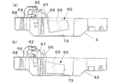
第1浮動体60は、図6に示すように、箱型のフロート65と、これに連結されたアーム66とによって構成される。フロート65は、ドレン受皿43のドレン水中に浮かべられ、フロート65の一側にアーム66が設けられている。アーム66は、上方に延び、ドレン受皿43の上面から突出して、折り曲げられ、アーム66の中間部分がドレン受皿43上の支持軸67に回動自在に支持される。これによって、第1浮動体60は支持軸67周りに揺動し、アーム66の先端が上下動する。
As shown in FIG. 6, the first floating
第1検出器62および第3検出器64は、リミットスイッチとされ、アーム66が接触することによりオンオフする機械的スイッチである。第1検出器62および第3検出器64は、ドレン受皿43の上面に設けられた台68上に設置され、第1検出器62が上側、第3検出器64が下側に位置する。
The
第1浮動体60のアーム66を揺動式とすることにより、第1検出器62および第3検出器64を近くに配置することができる。このような構造を採用すると、ドレン受皿43上の限られたスペースでも設置することができ、省スペース化を図れる。
By making the
図5に示すように、第1検出器62は、制御装置50に接続され、制御装置50は、第1検出器62のオンオフを検出して、ポンプ8の作動開始、停止を行う。そして、第3検出器64は、電源回路69と制御装置50との間に接続される。電源回路69は、商用電源に接続され、制御装置50の動作に必要な電源を供給する。第3検出器64には、ノーマルクローズのリミットスイッチが用いられ、通常はスイッチがオンしているので、電源回路69から制御装置50に電源が供給され、制御装置50は作動する。第3検出器64がオフすると、制御装置50への電源が遮断され、制御装置50は作動しなくなる。第3検出器64を電源回路69の上流側でなく下流側に設けているので、スイッチの電流容量を小さくでき、小型のスイッチを使用できる。
As shown in FIG. 5, the
第2浮動体61は、図7に示すように、真っ直ぐ上方に延びたピン70を有するフロート71とされる。第2浮動体61は、ガイド72によって上下方向に移動するように案内される。第2検出器63は、非接触式スイッチとされ、フォトインタラプタが用いられる。第2検出器63は、台68上に設置され、第2浮動体61のピン70が第2検出器63の受発光素子の間に形成された溝に出入りする。
As shown in FIG. 7, the second floating
第2検出器63は、制御装置50に接続され、発光素子が間欠的に駆動され、受光素子が受光状態に応じて信号を出力する。制御装置50は、第2検出器63からの出力により、満水状態と判断し、冷房運転や除湿運転を停止するとともに、ポンプ8も停止する。
The
第1浮動体60は、ドレン水の水位に応じて移動する。ドレン水が少ないとき、図6(b)に示すように、フロート65は水に浮かんでおらず、ドレン受皿43の底面に突設されたストッパ73に載った状態にある。このとき、アーム66は、第1検出器62に接触している。第1検出器62はオンしており、ポンプ8は停止している。
The first floating
そして、ドレン水が溜まり、フロート65が浮くと、アーム66は、第1検出器62から離れる。このときの水位が低水位となる。このように低水位に達すると、第1検出器62はオフし、ポンプ8が作動する。ドレン水が汲み上げられ、ドレン受皿43から排出される。なお、ポンプ8が作動して、ドレン水の水位が下がり、第1検出器43がオンすると、ポンプ8は停止する。このように水位が頻繁に変化すると、ポンプ8の作動、停止が繰り返される。そこで、第1検出器62のオフが一定時間継続したときに、ポンプ8の作動を開始するとよい。
When the drain water accumulates and the
さらに、冷房運転や除湿運転によりドレン水が発生して、ドレン受皿43に溜まっていく。また、凝縮器3によって蒸発しきれなかったドレン水も流れ落ちてくる。ドレン水の排出よりも供給が多いと、水位は上昇する。浮き上がった第2浮動体61のピン70が第2検出器63の溝内に侵入し、受発光素子間の光路を遮る。第2検出器63の出力によって満水状態が検出されると、運転が停止され、ポンプ8も停止する。これにより、ドレン受皿43に供給されるドレン水がなくなるので、水位は上がらない。
Further, drain water is generated by the cooling operation or the dehumidifying operation and is accumulated in the
このとき、排水ボタン53を操作すると、ポンプ8は強制的に一定時間、例えば1分間作動する。ドレン受皿43からドレン水が排出され、水位が下がる。これにより、再び運転が可能となる。なお、コックを回して、排水パイプ46に向かって排水される流路に切り替えておき、ドレン水は外部に排出される。
At this time, when the
ところで、第2検出器63あるいは第2浮動体61が何らかの原因によって、正常に作動しなかったとき、満水状態になっても、運転が停止せず、水位がさらに上がる。すると、図6(a)に示すように、第1浮動体60のアーム66が第3検出器64に接触する。このときの水位が異常水位となる。第3検出器64がオフして、電源回路69から制御装置50への電源供給が遮断され、制御装置50の作動が停止する。圧縮機2、ポンプ8等すべての動作が停止する。この場合、ユーザがドレン受皿43の栓を抜き、ドレン抜き孔44からドレン水を排出する。その後、リセットボタンを操作したり、電源を入れなおす等を行うことにより、制御装置50は作動し、運転を行える。
By the way, even if the
このように、2つの浮動体を用いて水位の変化を検出することにより、一方の浮動体や検出器に異常が発生しても、水位が上がったとき、他方の検出器が正常に動作して、運転を停止できる。したがって、ドレン受皿43からドレン水が溢れ出すことを防止でき、安全性が高まる。
In this way, by detecting changes in the water level using two floating bodies, even if an abnormality occurs in one floating body or detector, when the water level rises, the other detector operates normally. Operation can be stopped. Therefore, it is possible to prevent the drain water from overflowing from the
なお、本発明は、上記実施形態に限定されるものではなく、本発明の範囲内で上記実施形態に多くの修正および変更を加え得ることは勿論である。一体型空気調和機だけでなく、分離型空気調和機に適用してもよい。さらに、除湿機、冷蔵庫といった運転により水が発生する電気機器に適用してもよい。また、非接触式スイッチである第2検出器は、磁気スイッチとしてもよい。排水ボタンを運転ボタンと共用させる場合、運転ボタンを操作したとき、冷凍サイクル運転を開始させるとともに、所定時間だけポンプを作動させるようにしてもよい。ドレン水が溜まっているとき、ドレン水を減らすことができる。 In addition, this invention is not limited to the said embodiment, Of course, many corrections and changes can be added to the said embodiment within the scope of the present invention. You may apply not only to an integrated air conditioner but to a separation-type air conditioner. Furthermore, you may apply to the electric equipment which water generate | occur | produces by driving | operation, such as a dehumidifier and a refrigerator. Further, the second detector that is a non-contact switch may be a magnetic switch. When the drain button is shared with the operation button, when the operation button is operated, the refrigeration cycle operation may be started and the pump may be operated for a predetermined time. When drain water is accumulated, drain water can be reduced.
2 圧縮機
3 凝縮器
4 蒸発器
5 送風ファン
6 排気ファン
7 ダクト
8 ポンプ
50 制御装置
53 排水ボタン
60 第1浮動体
61 第2浮動体
62 第1検出器
63 第2検出器
64 第3検出器
69 電源回路
2
Claims (3)
前記水位検出装置は、水位の変化に応じて移動する第1浮動体および第2浮動体と、低水位を検出するための第1検出器と、低水位よりも高い高水位を検出するための第2検出器と、高水位よりも高い異常水位を検出するための第3検出器とを備え、前記第1検出器および第3検出器が前記第1浮動体と組み合わせられ、前記第2検出器が前記第2浮動体と組み合わせられ、
水位が低水位に達すると第1検出器が低水位を検出し、このとき、制御装置は、排出手段が作動中であれば、その作動を停止させ、排出手段が停止中であれば、第1検出器の低水位検出が一定時間継続したときに排出手段の作動を開始させ、また、第2検出器が高水位を検出したとき、冷凍サイクル運転を停止させ、さらに前記第3検出器が異常水位を検出したとき、前記制御装置に供給される電源がオフされることを特徴とする空気調和機。 According to the detected water level, a water reservoir for collecting drain water generated from the evaporator by the refrigeration cycle operation, a discharging means for discharging the drain water from the water reservoir, a water level detecting device for detecting the water level of the water reservoir, and A control device that performs refrigeration cycle operation and drive control of the discharge means,
The water level detection device includes a first floating body and a second floating body that move according to a change in the water level, a first detector for detecting a low water level, and a high water level that is higher than the low water level. A second detector and a third detector for detecting an abnormal water level higher than a high water level, wherein the first detector and the third detector are combined with the first floating body, and the second detection A vessel is combined with the second float,
When the water level reaches the low water level, the first detector detects the low water level. At this time, the control device stops the operation if the discharging means is operating, and if the discharging means is stopped, When the low water level detection of one detector continues for a certain time, the operation of the discharging means is started, and when the second detector detects a high water level, the refrigeration cycle operation is stopped, and the third detector When an abnormal water level is detected, the power supplied to the control device is turned off .
Priority Applications (1)
| Application Number | Priority Date | Filing Date | Title |
|---|---|---|---|
| JP2005050019A JP4430564B2 (en) | 2005-02-25 | 2005-02-25 | Air conditioner |
Applications Claiming Priority (1)
| Application Number | Priority Date | Filing Date | Title |
|---|---|---|---|
| JP2005050019A JP4430564B2 (en) | 2005-02-25 | 2005-02-25 | Air conditioner |
Publications (3)
| Publication Number | Publication Date |
|---|---|
| JP2006234286A JP2006234286A (en) | 2006-09-07 |
| JP2006234286A5 JP2006234286A5 (en) | 2007-04-19 |
| JP4430564B2 true JP4430564B2 (en) | 2010-03-10 |
Family
ID=37042145
Family Applications (1)
| Application Number | Title | Priority Date | Filing Date |
|---|---|---|---|
| JP2005050019A Expired - Fee Related JP4430564B2 (en) | 2005-02-25 | 2005-02-25 | Air conditioner |
Country Status (1)
| Country | Link |
|---|---|
| JP (1) | JP4430564B2 (en) |
Cited By (1)
| Publication number | Priority date | Publication date | Assignee | Title |
|---|---|---|---|---|
| KR101334257B1 (en) | 2012-07-04 | 2013-12-02 | (주)하이텍 | Magnet switch type removal pump |
Families Citing this family (1)
| Publication number | Priority date | Publication date | Assignee | Title |
|---|---|---|---|---|
| CN105843266B (en) * | 2016-06-13 | 2018-06-29 | 吴伟俊 | A kind of water level controller |
-
2005
- 2005-02-25 JP JP2005050019A patent/JP4430564B2/en not_active Expired - Fee Related
Cited By (1)
| Publication number | Priority date | Publication date | Assignee | Title |
|---|---|---|---|---|
| KR101334257B1 (en) | 2012-07-04 | 2013-12-02 | (주)하이텍 | Magnet switch type removal pump |
Also Published As
| Publication number | Publication date |
|---|---|
| JP2006234286A (en) | 2006-09-07 |
Similar Documents
| Publication | Publication Date | Title |
|---|---|---|
| JP4541923B2 (en) | Integrated air conditioner | |
| JP4495005B2 (en) | Air conditioner | |
| JP4676520B2 (en) | Integrated air conditioner | |
| JP2009236373A (en) | Integrated air conditioner | |
| CN113631864B (en) | Air conditioner and control method thereof | |
| JP2012057887A (en) | Air cleaner | |
| KR20060129677A (en) | A dehumidifier | |
| JP4430564B2 (en) | Air conditioner | |
| JP4460475B2 (en) | Integrated air conditioner | |
| JP2006234289A (en) | Integrated air-conditioner | |
| JP2010032111A (en) | Integrated air conditioner | |
| KR100393840B1 (en) | Air conditioner | |
| KR100784844B1 (en) | Apparatus for drying condensate in air conditioner | |
| JP4571520B2 (en) | Air conditioner control device | |
| KR102234780B1 (en) | Dehumidifier and method for controlling the same | |
| KR20060129678A (en) | A dehumidifier | |
| JP4495006B2 (en) | Air conditioner | |
| JP4473172B2 (en) | Integrated air conditioner | |
| JP4468839B2 (en) | Integrated air conditioner | |
| JP2006308191A (en) | Integrated air conditioner | |
| JP2004275924A (en) | Dehumidifier | |
| KR19990072235A (en) | Air conditioner | |
| KR100829101B1 (en) | Dehumidifier | |
| KR20060016003A (en) | Driving method of split type air conditioner | |
| JP2006234259A (en) | Suction pump and air-conditioner using the same |
Legal Events
| Date | Code | Title | Description |
|---|---|---|---|
| A521 | Written amendment |
Free format text: JAPANESE INTERMEDIATE CODE: A523 Effective date: 20070305 |
|
| A621 | Written request for application examination |
Free format text: JAPANESE INTERMEDIATE CODE: A621 Effective date: 20070305 |
|
| A977 | Report on retrieval |
Free format text: JAPANESE INTERMEDIATE CODE: A971007 Effective date: 20090119 |
|
| A131 | Notification of reasons for refusal |
Free format text: JAPANESE INTERMEDIATE CODE: A131 Effective date: 20090317 |
|
| A521 | Written amendment |
Free format text: JAPANESE INTERMEDIATE CODE: A523 Effective date: 20090512 |
|
| TRDD | Decision of grant or rejection written | ||
| A01 | Written decision to grant a patent or to grant a registration (utility model) |
Free format text: JAPANESE INTERMEDIATE CODE: A01 Effective date: 20091124 |
|
| A01 | Written decision to grant a patent or to grant a registration (utility model) |
Free format text: JAPANESE INTERMEDIATE CODE: A01 |
|
| A61 | First payment of annual fees (during grant procedure) |
Free format text: JAPANESE INTERMEDIATE CODE: A61 Effective date: 20091217 |
|
| FPAY | Renewal fee payment (event date is renewal date of database) |
Free format text: PAYMENT UNTIL: 20121225 Year of fee payment: 3 |
|
| R150 | Certificate of patent or registration of utility model |
Ref document number: 4430564 Country of ref document: JP Free format text: JAPANESE INTERMEDIATE CODE: R150 Free format text: JAPANESE INTERMEDIATE CODE: R150 |
|
| FPAY | Renewal fee payment (event date is renewal date of database) |
Free format text: PAYMENT UNTIL: 20121225 Year of fee payment: 3 |
|
| LAPS | Cancellation because of no payment of annual fees |