JP4429285B2 - Torque excitation device - Google Patents
Torque excitation device Download PDFInfo
- Publication number
- JP4429285B2 JP4429285B2 JP2006087954A JP2006087954A JP4429285B2 JP 4429285 B2 JP4429285 B2 JP 4429285B2 JP 2006087954 A JP2006087954 A JP 2006087954A JP 2006087954 A JP2006087954 A JP 2006087954A JP 4429285 B2 JP4429285 B2 JP 4429285B2
- Authority
- JP
- Japan
- Prior art keywords
- torque
- unit
- excitation
- coil
- drive
- Prior art date
- Legal status (The legal status is an assumption and is not a legal conclusion. Google has not performed a legal analysis and makes no representation as to the accuracy of the status listed.)
- Active
Links
- 230000005284 excitation Effects 0.000 title claims description 68
- 230000004907 flux Effects 0.000 claims description 27
- 238000001514 detection method Methods 0.000 claims description 8
- 230000000737 periodic effect Effects 0.000 claims description 2
- 238000000034 method Methods 0.000 description 13
- 230000000694 effects Effects 0.000 description 8
- 238000005259 measurement Methods 0.000 description 3
- 238000004804 winding Methods 0.000 description 3
- XEEYBQQBJWHFJM-UHFFFAOYSA-N Iron Chemical group [Fe] XEEYBQQBJWHFJM-UHFFFAOYSA-N 0.000 description 2
- 238000006073 displacement reaction Methods 0.000 description 2
- 238000004519 manufacturing process Methods 0.000 description 2
- 239000000853 adhesive Substances 0.000 description 1
- 230000001070 adhesive effect Effects 0.000 description 1
- 230000005540 biological transmission Effects 0.000 description 1
- 230000007423 decrease Effects 0.000 description 1
- 238000013461 design Methods 0.000 description 1
- 238000010586 diagram Methods 0.000 description 1
- 238000011156 evaluation Methods 0.000 description 1
- 230000003993 interaction Effects 0.000 description 1
- 238000012423 maintenance Methods 0.000 description 1
- 239000000463 material Substances 0.000 description 1
- 238000005096 rolling process Methods 0.000 description 1
- 238000012360 testing method Methods 0.000 description 1
- 238000012546 transfer Methods 0.000 description 1
Images


Description
この発明は、平面内の軸回りに対するトルク加振による伝達特性を取得することができるトルク加振装置に関するものである。 The present invention relates to a torque exciter that can acquire a transmission characteristic by torque excitation about an axis in a plane.
従来のトルク加振装置は、例えば、一対の励磁用磁石の間に、駆動体および交流電流が供給されるコイルを配置し、コイルが発生する磁束と励磁磁石が発生する磁束との相互作用により駆動体を軸回りに駆動させる構成となり、1軸回りのトルクを発生させる。これを用いて、平面内にトルク加振を入力する方法としては、回転体に意図的に動的不釣り合いを生じさせることで平面内にトルクを発生させることができる。しかし、この場合には、必ず複数軸回りのトルクを励起してしまう。さらに、回転体の回転により発生するトルクであるため動的不釣合いの大きさを変化させなければ、加振周波数に対して、発生トルクの大きさを変化させることができない。 In a conventional torque exciter, for example, a driving body and a coil to which an alternating current is supplied are arranged between a pair of exciting magnets, and the interaction between the magnetic flux generated by the coil and the magnetic flux generated by the exciting magnet is achieved. The driving body is driven around the axis, and torque around one axis is generated. As a method of inputting torque excitation in the plane using this, torque can be generated in the plane by intentionally causing dynamic imbalance in the rotating body. However, in this case, torque around multiple axes is always excited. Furthermore, since the torque is generated by the rotation of the rotating body, the magnitude of the generated torque cannot be changed with respect to the excitation frequency unless the magnitude of dynamic imbalance is changed.
従来のトルク加振装置は、トルク加振装置の駆動体と供試体を直結させて回転軸の回りにトルクを発生させるためねじり加振入力をすることは可能であるが、供試体のある面内にトルク加振を実施したい場合に平面に加振装置を取り付けてトルク加振を簡単に行うことができないという問題点があった。また、回転体に意図的な動バランス不釣り合いを設けることでトルクを平面内に生じさせる方法の場合には、純粋に一軸回りのトルクのみを発生させることができない。さらに、回転体の回転軸にベアリング等の軸受けが必要になり、転がり軸受けのため、小さいながらも摩擦力が存在する。また、回転にともないベアリングノイズが発生し、入力したい周波数成分以外に複数の周波数成分のトルクが生じてしまうという問題点もあった。また、回転数を固定するとその場合に発生させるトルクの大きさが変更できないという問題点もあった。 Conventional torque exciters can be input by torsional excitation in order to generate torque around the rotating shaft by directly connecting the drive unit of the torque exciter and the test object. When it is desired to perform torque excitation inside, there is a problem that torque excitation cannot be easily performed by attaching a vibration device to a flat surface. Further, in the case of a method in which torque is generated in a plane by providing intentional dynamic balance imbalance in the rotating body, it is not possible to generate purely torque around one axis. Furthermore, a bearing such as a bearing is required on the rotating shaft of the rotating body, and because of the rolling bearing, a small but frictional force exists. In addition, bearing noise is generated with rotation, and there is a problem that torque of a plurality of frequency components is generated in addition to the frequency component to be input. In addition, there is a problem that if the rotational speed is fixed, the magnitude of the torque generated in that case cannot be changed.
この発明は上記のような課題を解決するためになされたものであり、平面に対するトルク加振を得ることができるトルク加振装置を提供することを目的とする。 The present invention has been made to solve the above-described problems, and an object thereof is to provide a torque excitation device capable of obtaining torque excitation with respect to a plane.
この発明は、駆動部を支持する固定部に駆動部が駆動することで加振力が発生し加振力にともなってトルクが発生するトルク加振装置において、
回転軸を中心に対称に回動する駆動部と、駆動部を回動可能な状態にて支持する固定部と、回転軸を挟んで対称となる駆動部および固定部のそれぞれの箇所に配設された第1の発生部および第2の発生部と、第1および第2の発生部に電流を供給する電源部とを有し、
第1の発生部と第2の発生部とに、回転軸において互いに相反する方向かつ同一の大きさの電磁力を発生させて駆動部を駆動させるものである。
The present invention provides a torque excitation device in which an excitation force is generated by driving the drive unit to a fixed unit that supports the drive unit, and torque is generated along with the excitation force.
A drive unit that rotates symmetrically about the rotation axis, a fixed unit that supports the drive unit in a rotatable state, and a drive unit and a fixed unit that are symmetrical with respect to the rotation axis. A first generator and a second generator, and a power supply for supplying current to the first and second generators,
The first generation unit and the second generation unit generate electromagnetic forces in opposite directions and the same magnitude on the rotation axis to drive the drive unit.
この発明のトルク加振装置は、駆動部を支持する固定部に駆動部が駆動することで加振力が発生し加振力にともなってトルクが発生するトルク加振装置において、
回転軸を中心に対称に回動する駆動部と、駆動部を回動可能な状態にて保持する固定部と、回転軸を挟んで対称となる駆動部および固定部のそれぞれの箇所に配設された第1の発生部および第2の発生部と、第1および第2の発生部に電流を供給する電源部とを有し、
第1の発生部と第2の発生部とに、回転軸において互いに相反する方向かつ同一の大きさの電磁力を発生させて駆動部を駆動させるので、平面内の軸回りに対するトルク加振による伝達特性を取得することができる。
The torque excitation device according to the present invention is a torque excitation device in which an excitation force is generated by driving the drive unit to a fixed portion that supports the drive unit, and torque is generated along with the excitation force.
A drive unit that rotates symmetrically about the rotation axis, a fixed unit that holds the drive unit in a rotatable state, and a drive unit and a fixed unit that are symmetrical with respect to the rotation axis. A first generator and a second generator, and a power supply for supplying current to the first and second generators,
Since the first generating unit and the second generating unit generate electromagnetic forces in opposite directions and the same magnitude on the rotating shaft to drive the driving unit, the driving unit is driven by torque excitation around the axis in the plane. Transfer characteristics can be acquired.
実施の形態1.
以下、本願発明の実施の形態について説明する。様々な製品において、内部に搭載された駆動物が原因で振動が生じるために設計要求を満足できないという問題が発生する場合がある。例えば人工衛星では、内部に設置した搭載機器により力およびトルクによる加振により振動が発生し、人工衛星の構体をそれら振動が伝播することで、観測機器などの測定精度に影響をもたらすなどの問題点が挙げられている。この影響を評価する手法として、搭載機器の実機を設置して運転し、その影響を評価する方法や、数値解析により影響を評価する方法などがある。搭載機器の実機がある場合には前者の方法にて確認することが可能であるが、実機が存在しない場合にはこの方法を適応することができない。このため後者の方法にて確認することが必要となる。後者による振動解析評価を行う場合には、一般的に複数の加振入力を解析モデルに入れて解析することができないため、加振を1成分ごとすなわちX、Y、Z軸回りのトルクごとに入力し、その影響を評価することになる。この時、解析精度が問題となるため実測値を用いた構造モデルの合わせ込み精度を上げることが必要があり、その精度を評価する観点から各加振条件の実測データ取得を実施する必要がある。よってこのような場合に、この加振を発生することができる本願発明のトルク加振装置が用いられる。
Embodiments of the present invention will be described below. In various products, there may be a problem that the design requirement cannot be satisfied due to vibrations caused by a driving object mounted inside. For example, in an artificial satellite, vibrations are generated by the excitation by force and torque from the installed equipment inside, and the vibration propagates through the structure of the artificial satellite, thereby affecting the measurement accuracy of the observation equipment, etc. The point is mentioned. As a method for evaluating this influence, there are a method of installing and operating a real machine of the on-board equipment, evaluating the influence, and a method of evaluating the influence by numerical analysis. If there is a real machine of the mounted device, it can be confirmed by the former method, but this method cannot be applied if there is no real machine. For this reason, it is necessary to confirm by the latter method. When performing vibration analysis evaluation by the latter, since it is generally not possible to analyze a plurality of excitation inputs by putting them in an analysis model, excitation is performed for each component, that is, for each torque around the X, Y, and Z axes. Input and evaluate the impact. At this time, since the analysis accuracy becomes a problem, it is necessary to increase the accuracy of fitting the structural model using the actual measurement value, and it is necessary to acquire the actual measurement data for each excitation condition from the viewpoint of evaluating the accuracy . Therefore, in such a case, the torque excitation device of the present invention that can generate this excitation is used.
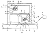
図1はこの発明の実施の形態1におけるトルク加振装置の構成を示す側面図、図2には図1に示したトルク加振装置の上面図、図3は図1に示したトルク加振装置のA−A’断面の構成を示した断面図、図4は図1に示したトルク加振装置の第1の発生部の詳細を示した図、図5は図1に示したトルク加振装置における加振力検知センサの配設位置を説明するための図である。図において、上記実施の形態1のトルク加振装置の構成およびトルク加振装置の動作を説明する。トルク加振装置は、駆動部1を支持する固定部2に駆動部1が駆動することで加振力が発生し加振力にともなってトルクが発生するものである。そして、駆動部1は回転軸3を中心に対称に回動し、固定部2は駆動部1を回動可能な状態にて支持する。さらに、回転軸3を挟んで対称となる駆動部1および固定部2のそれぞれの箇所に配設された第1の発生部4および第2の発生部5と、第1および第2の発生部4、5に所望の周波数を有する電流を供給する電源部6とを有し、第1の発生部4と第2の発生部5とに、回転軸3において互いに相反する方向かつ同一の大きさの電磁力を発生させて駆動部1を駆動させるものである。
1 is a side view showing a configuration of a torque excitation device according to
駆動部1は板状部材にて成り、その中央部の両端を回転軸3となる同軸の回転軸を有する十字ばね21、22にて固定部2の支柱部23に支持されている。また、支柱部23は板状部材にて成り供試体7(加振対象物)上に配設可能でかつ供試体7に加振を伝達する固定台24上に固設されている。そして、固定台24には4箇所にボルト用穴およびボルトにて成るボルト部2a、2b、2c、2dがそれぞれ形成され、供試体7にはこの各ボルト部2a、2b、2c、2dにおけるボルト止めにて固定されている。尚、固定台24の供試体7への固定方法はボルト止めに限られることはなく、他の方法においても固定可能であればよいことは言うまでもなく、例えば、固定台24を供試体7に対して接着剤にて固定する方法も考えられる。
The
そして、第1の発生部4および第2の発生部5は、その固定部側が、一定方向回りの磁束を形成する第1および第2の励磁用磁石部41、51にて構成される。この第1および第2の励磁用磁石部41、51は、固定台24の回転軸3を中心に左右対称の位置上にそれぞれ形成された縦断面Uの字状にて成り、磁束を形成しやすい材質にて成る第1および第2の保持部25、26の内壁面上の左右に対向し、上下に2組、例えば永久磁石にて成る第1ないし第4の励磁用磁石41a、41b、41c、41dおよび第5ないし第8の励磁用磁石51a、51b、51c、51dがそれぞれ固設されて構成される。そしてここでは、第1、第3、第5、第7の励磁用磁石41a、41c、51a、51cがN極、また、第2、第4、第6、第8の励磁用磁石41b、41d、51b、51dがS極にてそれぞれ構成されるものとする。よって第1の発生部4側を例に図4を用いて説明すると、第1の励磁用磁石41aから第2の励磁用磁石41bの方向への磁束イが生じ、第3の励磁用磁石41cから第4の励磁用磁石41dの方向への磁束ロが生じ、第1の保持部25内には磁束ハ、ニが生じ、第1の励磁用磁石部41には一定方向回りの磁束ホが形成されることとなる。尚、第2の励磁用磁石部51の第5ないし第8の励磁用磁石51a、51b、51c、51dにおいても、上記第1の励磁用磁石部41と同様に同一方向の磁束が生じているためのその説明を省略する。
And the
次に、第1および第2の発生部4、5の駆動部側は、第1および第2の励磁用磁石部41、51にて形成される磁束ホとそれぞれ交差するように配設された第1および第2のコイル部42、52にて構成される。さらにここでは、第1および第2の励磁用磁石部41、51にて形成される磁束ホと第1および第2のコイル部42、53を流れる電流とがそれぞれ直交するように配設されている。そして、この第1および第2のコイル部42、52は、駆動部1の回転軸3を中心に左右対称となる位置の下面側のそれぞれの位置に下部方向に延在して成る第3および第4の保持部11、12の内部に第1および第2のコイル43、53が内蔵されて成る。そして、この第1および第2のコイル43、53には電源部6から電流が供給される。
Next, the drive unit side of the first and
そして第1の発生部4においては、第1のコイル43は図4に示すように、上部側43aと下部側43bとではそれぞれ逆向きの電流が流れることとなる。ここでは、上部側43aには紙面上裏側方向に、下部側43bは紙面上表側方向に電流が流れている例を示している。よってこの場合には、上部側43aの紙面上裏側方向に流れる電流と第1および第2の励磁用磁石41a、41bとの間に生じている磁束イとからフレミングの左手の法則により下向きの電磁力、具体的には下向きのローレンツ力が発生する。また、下部側43bには上部側43aと逆向きの電流が流れるため、第3および第4の励磁用磁石41c、41dの間に生じる磁束ロとの間において同様にフレミングの左手の法則により下向きのローレンツ力が発生し、第1のコイル部42には、全体としてこの瞬間下向きの力が発生する。
In the
他方の第2の発生部5においては、磁束の方向が同一で第2のコイル53の巻き方向が逆向き、すなわち第1の発生部4の第1のコイル43と異なる方向に電流が流れるため、第2の発生部5にはこの瞬間、第1の発生部4と逆向きのすなわち上向きのローレンツ力が生じる。よって、第1の発生部4および第2の発生部5に、回転軸3において互いに相反する方向かつ同一の大きさの電磁力を発生させて駆動部1を駆動させることができる。そして、第1および第2のコイル43、53に流れる電流の向きは、周期的に変化するので、回転軸3の対称位置、ここでは左右一定距離で発生するローレンツ力の向きは、逆向きであるため回転軸3回りに矢印Aのモーメント、つまりトルクを生じさせることが可能である。
In the other
このとき、ローレンツ力は、回転軸3において相反する方向すなわち左右で逆向きであることから並進方向に発生する力は、打ち消され、回転軸3回りに、ローレンツ力とモーメントアームとの積による純粋なトルク成分のみが発生することになる。なお、このとき発生する力の対は、偶力であり、モーメントの和はどの位置でも同じ値となり、固定台4が固定されている供試体7の面にトルク加振ができる。そして、第1および第2のコイル43、53には、交流電流が流れることから発生する電磁力は、周期的に向きが反転する。このことで、一定周期のトルクが発生させることが可能である。第1および第2のコイル43、53に生じるローレンツ力も、第1および第2のコイル43、53間で力の方向は、180度異なる方向を維持したまま、その周波数に従い変化する。
At this time, since the Lorentz force is in the opposite direction on the
また、第1の保持部25の内部下面上には図5に示すように加振力検知センサ8を設置している。この加振力検知センサ8により第1の保持部25と第1のコイル43を内蔵している第3の保持部11との距離を計測し、その信号を用いて、トルク加振装置の加振方向を判定する。つまり、加振トルクの大きさと位相関係とを把握することが可能となる。尚、ここで示した検知以外の方法でも、第1のコイル42を内蔵している第3の保持部11の運動方向が把握できるものであれば同様に検知することが可能となり同様の効果を奏することが可能となる。また、加振力検知センサ8は以下の実施の形態においても同様に設置することが可能でありその説明は適宜省略する。
Further, an excitation
また、図1においてはトルク加振装置を水平に配設する例を示したが、例えば図6に示すように、供試体70が垂直に存在する場合、トルク加振装置を垂直方向に配設することも可能である。この場合、駆動体1の上部に配設されている例えばアンバランス調整マス9a、9bを、図1の回転軸3の上下、左右について駆動部1をつり合わせる用にそれぞれ調整すれば、トルク加振装置を垂直に立てた場合でも上記に示した水平状態の場合と同様にトルク加振を行うことができ同様の効果を奏することが可能となる。
1 shows an example in which the torque exciter is arranged horizontally. For example, as shown in FIG. 6, when the
上記のように構成された実施の形態1のトルク加振装置によれば、回転軸を挟んで対称となる二箇所に第1および第2の発生部を配設することで、一定周期のトルクが発生させることが可能であり、平面にトルクを1軸方向のみを純粋励起することが可能になる。また、固定部と駆動部間で駆動力を発生させるため装置自体がコンパクトになる。また、固定部と駆動部との回転の支持を十字ばねを配設して行っているため、摩擦がなく、例えば回転軸にベアリングを用いた場合に生じるような回転による微小なガタやベアリングの回転伴うベアリングノイズが発生することを抑えることが可能となり、略単一周波数のトルク成分のみを発生させることができる。また、第1および第2の励磁用磁石部にて形成される磁束と第1および第2のコイル部を流れる電流とがそれぞれ直交するように、第1および第2の励磁用磁石部および上記第1および第2のコイル部が配設されているため、効率よくローレンツ力を発生させることができる。 According to the torque exciter of the first embodiment configured as described above, the first and second generators are arranged at two symmetrical positions with the rotating shaft in between, thereby providing a constant period of torque. It is possible to generate a torque, and it is possible to purely excite a torque in only one axial direction on a plane. Further, since the driving force is generated between the fixed part and the driving part, the apparatus itself becomes compact. In addition, because the rotation of the fixed part and the drive part is supported by a cross spring, there is no friction and, for example, a small backlash or bearing caused by rotation that occurs when a bearing is used for the rotating shaft. It is possible to suppress the occurrence of bearing noise accompanying rotation, and it is possible to generate only a torque component having a substantially single frequency. Further, the first and second exciting magnet parts and the above-mentioned ones are arranged so that the magnetic flux formed by the first and second exciting magnet parts and the currents flowing through the first and second coil parts are orthogonal to each other. Since the first and second coil portions are disposed, the Lorentz force can be generated efficiently.
尚、上記実施の形態1では特に示していないが、第1の発生部および第2の発生部の固定部側および駆動部側が接触しない範囲内(形状的な制約範囲内)であれば、可動角度の変更は可能である。また、この接触しない範囲であれば、電流レベルを変更して、発生トルクを調整することが可能となる。 Although not particularly shown in the first embodiment, it is movable as long as it is within the range where the fixed part side and the drive part side of the first and second generating parts are not in contact (within the shape restriction range). The angle can be changed. Further, within this non-contact range, the generated torque can be adjusted by changing the current level.
また、図7に示すように、上記に示した実施の形態1とは異なり、第1および第2の発生部4、5の駆動部側と固定部側とを反対に形成する場合も考えられる。すなわち、第1および第2の保持部24、25を駆動部1側に配設し、第3および第4の保持部11、12を固定部2側にそれぞれ配設し、第1および第2の発生部4、5の駆動部側に、一定方向回りの磁束を形成する第1および第2の励磁用磁石部41、51を構成し、第1および第2の発生部4、5の固定部側に、第1および第2の励磁用磁石部41、51にて形成される磁束とそれぞれ交差するように配設された第1および第2のコイル部42、52を構成しかつ電源部6から電流が供給されるように構成してもよい。このように構成すれば、上記実施の形態1に示した場合と同様に、第1の励磁用磁石部41と第1のコイル部42との間、および、第2の励磁用磁石部51と第2のコイル部52との間にはローレンツ力がそれぞれ生じ、上記実施の形態1と同様にトルク加振を発生させ、上記実施の形態1と同様の効果を奏することが可能である。尚、このように第1および第2の発生部における駆動部側と固定部側とを反対に形成することができる場合は、以下の実施の形態においても同様に行うことができるものもありその説明は適宜省略する。
Further, as shown in FIG. 7, unlike the above-described first embodiment, it is conceivable that the driving part side and the fixed part side of the first and
実施の形態2.
図8はこの発明の実施の形態2におけるトルク加振装置の構成を示す側面図である。図において、上記実施の形態1と同様部分は同一符号を付して説明を省略する。上記実施の形態1では、左右の第1および第2のコイル43、53の巻線方向を逆方向に形成し、交差する一定方向回りの磁束を左右共に同じ回転方向に設ける例を示したが、本実施の形態2においては、図8に示すように第2の発生部2の第5ないし第8の励磁用磁石51a、51b、51c、51dの配置を変更して、第1および第2の発生部4、5における一定方向回りの磁束ホ、トの回転方向を、左右で逆回りの回転方向となるように形成する。そして、第2のコイル部52の第2のコイル53aを第1のコイル43の巻線方向と同一方向に変更する。このようにすれば、第1および第2のコイル43、53aに流れる交流電流の向きが左右ともに同じとなり、磁束の回転方向が逆回りとなるため、上記実施の形態1と同様に動作し、同様の効果を奏することが可能である。
FIG. 8 is a side view showing the configuration of the torque excitation device according to
実施の形態3.
上記各実施の形態では、駆動部1の質量について特に示していないが、例えば駆動部1の上面にねじ部を設けて、質量を付加することも可能である。尚、この実施の形態3における質量の付加の方法は特に図示しないため、図1に基づいて説明する。このように質量を付加できるようにすると、回転軸3回りの慣性モーメントが増加させることが可能となり、慣性モーメントが小さいときに比べて、同じトルクの大きさを発生させる場合でも、駆動部1の回転角度範囲を小さく保つことができる。すなわち、第1および第2の励磁用磁石部41、51と第1および第2のコイル部42、52との間のクリアランスを変えることなく、駆動部1に質量を付加することにて発生トルクを大きくすることが可能となる。その理由は次の通りである。一般に、電磁力Fと回転軸3からの距離lを用い、その発生する周波数f、時間をtとすると、トルクTrは、式(1)にて示すことができる。
In each of the above embodiments, the mass of the

一方、駆動部1の慣性モーメントIである場合、式(2)の関係が成り立つ。
On the other hand, in the case of the moment of inertia I of the
この式(2)から、回転軸回りの角度変位θは、次式(3)で示される。 From this equation (2), the angular displacement θ around the rotation axis is expressed by the following equation (3).
つまり、同一トルクの場合には、周波数fが低いほど角度変位θは大きくなる。そのため、低周波数でも大きなトルクを出したい場合には、駆動部1上に質量を付加することで回転角度に余裕を持たせ、大きなトルクを発生させることが可能となる。
That is, in the case of the same torque, the angular displacement θ increases as the frequency f decreases. Therefore, when it is desired to generate a large torque even at a low frequency, it is possible to generate a large torque by adding a mass on the
実施の形態4.
図9はこの発明の実施の形態4におけるトルク加振装置の構成を示す側面図である。図において、上記各実施の形態と同様の部分は同一符号を付して説明を省略する。図において、上記各実施の形態においては第1および第2の発生部4、5を回転軸3に対して左右対称な箇所にそれぞれ形成する例を示したが、この発明の実施の形態4においては、第1および第2の発生部4、5を、回転軸3に対して点対称な位置に配設する。そのために、固定部3の固定台24上に躯体部27を形成し、第1の保持部28を躯体部27の上部に、第2の保持部29を固定台24上に、回転軸3に対して点対称となる位置に、第1および第2の保持部28、29はその内壁が同様の曲率を有する面となるようにそれぞれ形成されている。
FIG. 9 is a side view showing the configuration of the torque excitation device according to
そして、上記実施の形態1と同様に第1ないし第8の励磁用磁石41a、41b、41c、41d、51a、51b、51c、51dがそれぞれ固設され第1および第2の励磁用磁石部41、51が形成されている。また、駆動部1の一端の上面側および他端の下面側には第1および第2の保持部28、29の内壁と同様の曲率を有する用に第3および第4の保持部13、14が回転軸3に対して点対称となる位置に形成されている。よって、第1および第2のコイル43、53と常に平行となるよう同様の曲率で第1ないし第8の励磁用磁石41a、41b、41c、41d、51a、51b、51c、51dが固設されることとなる。このように構成すれば、上記実施の形態1と同様にローレンツ力を発生することが可能となり、上記実施の形態1と同様の効果を奏することができる。
Similarly to the first embodiment, the first to eighth
尚、上記実施の形態4では、第1および第2の発生部4、5において、図9に示すような第1ないし第8の励磁用磁石41a、41b、41c、41d、51a、51b、51c、51dおよび第1および第2のコイル42、52を配置する例を示したが、回転軸に対して点対称な位置で逆向きのローレンツ力が発生するような励磁用磁石およびコイルの配置であれば他の配置であっても上記実施の形態4と同様の効果を奏することが可能であることは言うまでもない。
In the fourth embodiment, in the first and
実施の形態5.
図10はこの発明の実施の形態5におけるトルク加振装置の構成を示す側面図である。図において、上記各実施の形態と同様の部分は同一符号を付して説明を省略する。上記実施の形態1と同様に第1および第2の発生部4、5を回転軸3に対して左右対称な箇所にそれぞれ形成する他の例を示す。この発明の実施の形態5においては、第1および第2の発生部4、5を、回転軸3に対して左右対称な位置に設置するために、固定部3の固定台24上に第1および第2の保持部30、31を縦断面Cの字状でかつ駆動部1の端部をそれぞれ挿入可能に形成し、上記実施の形態1と同様に第1ないし第8の励磁用磁石41a、41b、41c、41d、51a、51b、51c、51dがそれぞれの内壁の左右に対向し、駆動部1の上下位置に2組ずつ固設され、第1および第2の励磁用磁石部41、51が形成されている。
FIG. 10 is a side view showing the configuration of the torque excitation device according to
また、駆動部1の一端および他端の両端には第1および第2の保持部30、31の内壁に沿うように駆動部1の上部側および下部側に延在するように、かつ、回転軸3に対して左右対称となる位置に第3および第4の保持部15、16が形成されている。第3および第4の保持部15、16に保持されている第1および第2のコイル43、53は、第1および第2の励磁用磁石部41、51にて形成される磁束とそれぞれ交差するように配設されている。さらにここでは、第1および第2の励磁用磁石部41、51にて形成される磁束と第1および第2のコイル部42、53を流れる電流とがそれぞれ直交するように配設されている。このように構成すれば、上記実施の形態1と同様にローレンツ力を発生することが可能なり、上記実施の形態1と同様の効果を奏することができる。
Further, both ends of the
尚、上記実施の形態5では、第1および第2の発生部4、5において、図10のように示すような第1ないし第8の励磁用磁石41a、41b、41c、41d、51a、51b、51c、51dおよび第1および第2のコイル42、52を配置する例を示したが、回転軸に対して左右対称な位置で左右逆向きのローレンツ力が発生するような励磁用磁石およびコイルの配置であれば他の配置であっても上記実施の形態5と同様の効果を奏することは言うまでもない。
In the fifth embodiment, in the first and
実施の形態6.
上記各実施の形態においては、電磁力としてローレンツ力を生じさせ、この力が回転軸よりオフセットして発生することにより回転軸回りにトルクを発生させる場合について説明したが、以下の実施の形態においては、電磁力として電磁吸引力を用いる場合について説明する。図11はこの発明の実施の形態6におけるトルク加振装置の構成を示す側面図である。図において、上記各実施の形態と同様な部分は同一符号を付して説明を省略する。固定台24上の駆動部1の回転軸3の左右対称の位置に第1および第2の保持部32、33がそれぞれ形成されている。そして、第1の保持部32には駆動部1の一端の上下位置に、第1の発生部4としての、第1および第2の鉄心44b、45bを備えた第1および第2のコイル44a、45aにて成る第1および第2のコイル部44、45が保持され形成されている。また、第2の保持部33には駆動部1の他端の上下位置に、第2の発生部5としての、第3および第4の鉄心54b、55bを備えた第3および第4のコイル54a、55aにて成る第3および第4のコイル部54、55が保持され形成されている。そして、第1ないし第4のコイル44a、45a、54a、55aには電源部6から電流が供給されている。
In each of the above-described embodiments, a case where a Lorentz force is generated as an electromagnetic force and this force is generated by being offset from the rotation shaft to generate a torque around the rotation shaft has been described. The case where an electromagnetic attraction force is used as the electromagnetic force will be described. FIG. 11 is a side view showing the configuration of the torque excitation device according to
次に、上記のように構成された実施の形態6のトルク加振装置の動作について説明する。まず、第1および第3のコイル44a、54aに電流を流した場合には、第1の発生部4側には、第1のコイル部44と駆動部1との間には磁気吸引力が働き、駆動部1は時計回りに回転する。さらに、第2の発生部5側には、第3のコイル部54と駆動部1の間に電磁吸引力が働き、駆動部1は回転軸3の時計回りにトルクを生じる。このとき発生する磁束の方向は、図11(a)に示す磁束チに示すようになる。一方、第2および第4のコイル45a、55aに電流を流した場合には、第1の発生部4側には第2のコイル部45と駆動部1の間、第2の発生部5側には第4のコイル部55と駆動部1との間には磁気吸引力が発生し、回転軸3の回りに反時計回りにトルクを生じされることが可能である。この時に発生する磁束の方向は、図11(b)に示す磁束リに示すようになる。このように第1ないし第4のコイル部44、45、54、55を組み合わせることで、第1および第2の発生部4、5において、交互に一定周期で電流を流すことで周期的な回転トルクを生じさせることが可能である。よって、上記実施の形態6のように発生する磁気吸引力は、上記実施の形態1と同様に、回転軸の左右で逆向きであり、磁気吸引力が同じ大きさであるため並進方向の力は発生せず、純粋な1軸回りのトルク成分を発生させることが可能となる。
Next, the operation of the torque excitation device according to the sixth embodiment configured as described above will be described. First, when a current is passed through the first and
上記のように構成された実施の形態6によれば、上記実施の形態1と同様に回転軸を挟んで対称となる二箇所に第1および第2の発生部を配設することで、一定周期のトルクが発生させることが可能であり、平面にトルクを1軸方向のみを純粋励起することが可能になる。また、固定部と駆動部間で駆動力を発生させるため装置自体がコンパクトになる。また、固定部と駆動部との回転の支持を十字ばねを配設して行っているため、摩擦がなく、例えば回転軸にベアリングを用いた場合に生じるような回転による微小なガタやベアリングの回転伴うベアリングノイズが発生することを抑えることが可能となり、略単一周波数のトルク成分のみを発生させることができる。 According to the sixth embodiment configured as described above, as in the first embodiment, the first and second generators are arranged at two symmetrical positions with the rotation axis in between, thereby providing a constant. Periodic torque can be generated, and it is possible to purely excite torque in only one axial direction on a plane. Further, since the driving force is generated between the fixed part and the driving part, the apparatus itself becomes compact. In addition, because the rotation of the fixed part and the drive part is supported by a cross spring, there is no friction and, for example, a small backlash or bearing caused by rotation that occurs when a bearing is used for the rotating shaft. It is possible to suppress the occurrence of bearing noise accompanying rotation, and it is possible to generate only a torque component having a substantially single frequency.
実施の形態7.
図12はこの発明の実施の形態7におけるトルク加振装置の構成を示す側面図である。図において、上記各実施の形態と同様部分は同一符号を付して説明を省略する。本実施の形態7では、駆動部1の端部に図12に示すような傾斜面1a、1b、1c、1dを形成し、この傾斜面1a、1b、1c、1dに対して第1ないし第4のコイル部44、45、54、55が対向するように傾斜させて配設する。このように構成すれば、上記実施の形態6と同様に磁束が発生するとともに、上記実施の形態6と比較して、駆動部1の回転軸3回りの回転角度範囲を傾斜面を形成している分広げることが可能である。よって、上記式(3)からも分かるよう、回転角度を大きく設定することにより大きなトルクを発生させることが可能となる。
FIG. 12 is a side view showing the configuration of the torque excitation device according to
1 駆動部、2 固定部、3 回転軸、4 第1の発生部、5 第2の発生部、
6 電源部、7,70 供試体、8 加振力検知センサ、21,22 十字ばね、
41 第1の励磁用磁石部、42,44 第1のコイル部、51 第2の励磁用磁石部、
52,45 第2のコイル部、54 第3のコイル部、55 第4のコイル部。
DESCRIPTION OF
6 Power supply unit, 7, 70 Specimen, 8 Excitation force detection sensor, 21, 22 Cross spring,
41 1st exciting magnet part, 42, 44 1st coil part, 51 2nd exciting magnet part,
52, 45 2nd coil part, 54 3rd coil part, 55 4th coil part.
Claims (5)
回転軸を中心に対称に回動する上記駆動部と、上記駆動部を回動可能な状態にて支持する上記固定部と、上記回転軸を挟んで対称となる上記駆動部および上記固定部のそれぞれの箇所に配設された第1の発生部および第2の発生部と、上記第1および第2の発生部に電流を供給する電源部とを有し、
上記第1の発生部および上記第2の発生部に、上記回転軸において互いに相反する方向かつ同一の大きさの電磁力を発生させて上記駆動部を駆動させてトルク加振することを特徴とするトルク加振装置。 In a torque excitation device that generates an excitation force by driving the drive unit to a fixed unit that supports the drive unit and generates a torque in accordance with the excitation force,
The drive unit that rotates symmetrically about a rotation axis, the fixed unit that supports the drive unit in a rotatable state, the drive unit that is symmetric with respect to the rotation axis, and the fixed unit. A first generator and a second generator disposed at each location; and a power supply that supplies current to the first and second generators.
The first generation unit and the second generation unit generate electromagnetic forces in opposite directions and the same magnitude on the rotation shaft to drive the drive unit to generate torque. Torque excitation device.
Priority Applications (1)
| Application Number | Priority Date | Filing Date | Title |
|---|---|---|---|
| JP2006087954A JP4429285B2 (en) | 2006-03-28 | 2006-03-28 | Torque excitation device |
Applications Claiming Priority (1)
| Application Number | Priority Date | Filing Date | Title |
|---|---|---|---|
| JP2006087954A JP4429285B2 (en) | 2006-03-28 | 2006-03-28 | Torque excitation device |
Publications (3)
| Publication Number | Publication Date |
|---|---|
| JP2007263680A JP2007263680A (en) | 2007-10-11 |
| JP2007263680A5 JP2007263680A5 (en) | 2007-11-22 |
| JP4429285B2 true JP4429285B2 (en) | 2010-03-10 |
Family
ID=38636823
Family Applications (1)
| Application Number | Title | Priority Date | Filing Date |
|---|---|---|---|
| JP2006087954A Active JP4429285B2 (en) | 2006-03-28 | 2006-03-28 | Torque excitation device |
Country Status (1)
| Country | Link |
|---|---|
| JP (1) | JP4429285B2 (en) |
Cited By (1)
| Publication number | Priority date | Publication date | Assignee | Title |
|---|---|---|---|---|
| WO2020164186A1 (en) * | 2019-02-13 | 2020-08-20 | 安徽理工大学 | Six-degree-of-freedom series-parallel electromagnetic vibration test stand |
Families Citing this family (4)
| Publication number | Priority date | Publication date | Assignee | Title |
|---|---|---|---|---|
| JP2014169980A (en) * | 2013-03-05 | 2014-09-18 | Sharp Corp | Vibration device |
| CN105119449B (en) * | 2015-09-15 | 2017-06-27 | 中国计量学院 | The big torque vibrator of finite angle |
| CN107246946A (en) * | 2017-05-19 | 2017-10-13 | 哈尔滨工程大学 | A kind of dynamic pulse moment of torsion excitation generating means of rotary axis |
| CN109596424B (en) * | 2019-01-07 | 2024-02-13 | 无锡奥特维科技股份有限公司 | Tension testing device |
-
2006
- 2006-03-28 JP JP2006087954A patent/JP4429285B2/en active Active
Cited By (1)
| Publication number | Priority date | Publication date | Assignee | Title |
|---|---|---|---|---|
| WO2020164186A1 (en) * | 2019-02-13 | 2020-08-20 | 安徽理工大学 | Six-degree-of-freedom series-parallel electromagnetic vibration test stand |
Also Published As
| Publication number | Publication date |
|---|---|
| JP2007263680A (en) | 2007-10-11 |
Similar Documents
| Publication | Publication Date | Title |
|---|---|---|
| JP4429285B2 (en) | Torque excitation device | |
| JP5532455B2 (en) | Acceleration and rotational speed detection method and MEMS sensor | |
| JP5937954B2 (en) | A device for measuring the dynamic characteristics of a centrifugal rotating machine, and a centrifugal rotating machine. | |
| CA2334856C (en) | Method and apparatus for a sensitivity enhancing balance bar | |
| Ghommem et al. | Modeling and performance study of a beam microgyroscope | |
| Shi et al. | A ring-type multi-DOF ultrasonic motor with four feet driving consistently | |
| CN106248328B (en) | A kind of indirect method measuring shafting structure torsion dynamic flexibility | |
| Horst et al. | Active vibration control of a high speed rotor using PZT patches on the shaft surface | |
| JP5831869B2 (en) | Vibration reduction device for reciprocating machine and reciprocating machine | |
| Lecointe et al. | Five methods of stator natural frequency determination: case of induction and switched reluctance machines | |
| JP2014096924A (en) | Power generation element | |
| Dang et al. | Triple degree-of-freedom piezoelectric ultrasonic micromotor via flexural-axial | |
| KR100905397B1 (en) | Dynamic balancing apparatus and methods using periodic angular motion | |
| JPH08297050A (en) | Method for evaluating vibration of rotating body in static field | |
| JP6303846B2 (en) | Vibration power generator | |
| JP5940343B2 (en) | Power generation element | |
| JP2007263680A5 (en) | ||
| Yaguchi et al. | A novel magnetic actuator capable of free movement on a magnetic substance | |
| JP2011007749A (en) | Inertia moment measuring device | |
| Tonoli et al. | Electromechanical dampers for vibration control of structures and rotors | |
| Kim et al. | Dynamic analysis of a pulley-belt system with different pulley radii and support stiffness | |
| KR100701628B1 (en) | The torsional vibration simulator used magnetic force | |
| Huo et al. | Unbalance identification for mainshaft system of 2-DOF precision centrifuge: a displacement sensor-based approach | |
| JP3738593B2 (en) | Method for measuring excitation force of vibration generator | |
| Kitayama et al. | DEVELOPMENT OF 2 DOF LINEAR OSCILLATORY ACTUATOR FOR VIBRATION CONTROL |
Legal Events
| Date | Code | Title | Description |
|---|---|---|---|
| A521 | Request for written amendment filed |
Free format text: JAPANESE INTERMEDIATE CODE: A523 Effective date: 20070921 |
|
| A621 | Written request for application examination |
Free format text: JAPANESE INTERMEDIATE CODE: A621 Effective date: 20070921 |
|
| A977 | Report on retrieval |
Free format text: JAPANESE INTERMEDIATE CODE: A971007 Effective date: 20090401 |
|
| TRDD | Decision of grant or rejection written | ||
| A01 | Written decision to grant a patent or to grant a registration (utility model) |
Free format text: JAPANESE INTERMEDIATE CODE: A01 Effective date: 20091215 |
|
| A01 | Written decision to grant a patent or to grant a registration (utility model) |
Free format text: JAPANESE INTERMEDIATE CODE: A01 |
|
| A61 | First payment of annual fees (during grant procedure) |
Free format text: JAPANESE INTERMEDIATE CODE: A61 Effective date: 20091215 |
|
| FPAY | Renewal fee payment (event date is renewal date of database) |
Free format text: PAYMENT UNTIL: 20121225 Year of fee payment: 3 |
|
| R150 | Certificate of patent or registration of utility model |
Ref document number: 4429285 Country of ref document: JP Free format text: JAPANESE INTERMEDIATE CODE: R150 Free format text: JAPANESE INTERMEDIATE CODE: R150 |
|
| FPAY | Renewal fee payment (event date is renewal date of database) |
Free format text: PAYMENT UNTIL: 20121225 Year of fee payment: 3 |
|
| FPAY | Renewal fee payment (event date is renewal date of database) |
Free format text: PAYMENT UNTIL: 20131225 Year of fee payment: 4 |
|
| R250 | Receipt of annual fees |
Free format text: JAPANESE INTERMEDIATE CODE: R250 |
|
| R250 | Receipt of annual fees |
Free format text: JAPANESE INTERMEDIATE CODE: R250 |
|
| R250 | Receipt of annual fees |
Free format text: JAPANESE INTERMEDIATE CODE: R250 |
|
| R250 | Receipt of annual fees |
Free format text: JAPANESE INTERMEDIATE CODE: R250 |
|
| R250 | Receipt of annual fees |
Free format text: JAPANESE INTERMEDIATE CODE: R250 |
|
| R250 | Receipt of annual fees |
Free format text: JAPANESE INTERMEDIATE CODE: R250 |
|
| R250 | Receipt of annual fees |
Free format text: JAPANESE INTERMEDIATE CODE: R250 |
|
| R250 | Receipt of annual fees |
Free format text: JAPANESE INTERMEDIATE CODE: R250 |
|
| R250 | Receipt of annual fees |
Free format text: JAPANESE INTERMEDIATE CODE: R250 |