JP4424856B2 - Optimization method of ultrasonic color flow display by adjusting threshold - Google Patents
Optimization method of ultrasonic color flow display by adjusting threshold Download PDFInfo
- Publication number
- JP4424856B2 JP4424856B2 JP2000592668A JP2000592668A JP4424856B2 JP 4424856 B2 JP4424856 B2 JP 4424856B2 JP 2000592668 A JP2000592668 A JP 2000592668A JP 2000592668 A JP2000592668 A JP 2000592668A JP 4424856 B2 JP4424856 B2 JP 4424856B2
- Authority
- JP
- Japan
- Prior art keywords
- data
- signal
- data words
- response
- threshold
- Prior art date
- Legal status (The legal status is an assumption and is not a legal conclusion. Google has not performed a legal analysis and makes no representation as to the accuracy of the status listed.)
- Expired - Fee Related
Links
Images


Classifications
-
- G—PHYSICS
- G01—MEASURING; TESTING
- G01S—RADIO DIRECTION-FINDING; RADIO NAVIGATION; DETERMINING DISTANCE OR VELOCITY BY USE OF RADIO WAVES; LOCATING OR PRESENCE-DETECTING BY USE OF THE REFLECTION OR RERADIATION OF RADIO WAVES; ANALOGOUS ARRANGEMENTS USING OTHER WAVES
- G01S15/00—Systems using the reflection or reradiation of acoustic waves, e.g. sonar systems
- G01S15/88—Sonar systems specially adapted for specific applications
- G01S15/89—Sonar systems specially adapted for specific applications for mapping or imaging
- G01S15/8906—Short-range imaging systems; Acoustic microscope systems using pulse-echo techniques
- G01S15/8979—Combined Doppler and pulse-echo imaging systems
- G01S15/8988—Colour Doppler imaging
-
- G—PHYSICS
- G01—MEASURING; TESTING
- G01S—RADIO DIRECTION-FINDING; RADIO NAVIGATION; DETERMINING DISTANCE OR VELOCITY BY USE OF RADIO WAVES; LOCATING OR PRESENCE-DETECTING BY USE OF THE REFLECTION OR RERADIATION OF RADIO WAVES; ANALOGOUS ARRANGEMENTS USING OTHER WAVES
- G01S15/00—Systems using the reflection or reradiation of acoustic waves, e.g. sonar systems
- G01S15/88—Sonar systems specially adapted for specific applications
- G01S15/89—Sonar systems specially adapted for specific applications for mapping or imaging
- G01S15/8906—Short-range imaging systems; Acoustic microscope systems using pulse-echo techniques
- G01S15/8979—Combined Doppler and pulse-echo imaging systems
-
- G—PHYSICS
- G01—MEASURING; TESTING
- G01S—RADIO DIRECTION-FINDING; RADIO NAVIGATION; DETERMINING DISTANCE OR VELOCITY BY USE OF RADIO WAVES; LOCATING OR PRESENCE-DETECTING BY USE OF THE REFLECTION OR RERADIATION OF RADIO WAVES; ANALOGOUS ARRANGEMENTS USING OTHER WAVES
- G01S7/00—Details of systems according to groups G01S13/00, G01S15/00, G01S17/00
- G01S7/52—Details of systems according to groups G01S13/00, G01S15/00, G01S17/00 of systems according to group G01S15/00
- G01S7/52017—Details of systems according to groups G01S13/00, G01S15/00, G01S17/00 of systems according to group G01S15/00 particularly adapted to short-range imaging
- G01S7/52023—Details of receivers
- G01S7/52034—Data rate converters
-
- G—PHYSICS
- G01—MEASURING; TESTING
- G01S—RADIO DIRECTION-FINDING; RADIO NAVIGATION; DETERMINING DISTANCE OR VELOCITY BY USE OF RADIO WAVES; LOCATING OR PRESENCE-DETECTING BY USE OF THE REFLECTION OR RERADIATION OF RADIO WAVES; ANALOGOUS ARRANGEMENTS USING OTHER WAVES
- G01S7/00—Details of systems according to groups G01S13/00, G01S15/00, G01S17/00
- G01S7/52—Details of systems according to groups G01S13/00, G01S15/00, G01S17/00 of systems according to group G01S15/00
- G01S7/52017—Details of systems according to groups G01S13/00, G01S15/00, G01S17/00 of systems according to group G01S15/00 particularly adapted to short-range imaging
- G01S7/52053—Display arrangements
- G01S7/52057—Cathode ray tube displays
- G01S7/52071—Multicolour displays; using colour coding; Optimising colour or information content in displays, e.g. parametric imaging
-
- G—PHYSICS
- G01—MEASURING; TESTING
- G01S—RADIO DIRECTION-FINDING; RADIO NAVIGATION; DETERMINING DISTANCE OR VELOCITY BY USE OF RADIO WAVES; LOCATING OR PRESENCE-DETECTING BY USE OF THE REFLECTION OR RERADIATION OF RADIO WAVES; ANALOGOUS ARRANGEMENTS USING OTHER WAVES
- G01S7/00—Details of systems according to groups G01S13/00, G01S15/00, G01S17/00
- G01S7/52—Details of systems according to groups G01S13/00, G01S15/00, G01S17/00 of systems according to group G01S15/00
- G01S7/52017—Details of systems according to groups G01S13/00, G01S15/00, G01S17/00 of systems according to group G01S15/00 particularly adapted to short-range imaging
- G01S7/52053—Display arrangements
- G01S7/52057—Cathode ray tube displays
- G01S7/5206—Two-dimensional coordinated display of distance and direction; B-scan display
-
- G—PHYSICS
- G01—MEASURING; TESTING
- G01S—RADIO DIRECTION-FINDING; RADIO NAVIGATION; DETERMINING DISTANCE OR VELOCITY BY USE OF RADIO WAVES; LOCATING OR PRESENCE-DETECTING BY USE OF THE REFLECTION OR RERADIATION OF RADIO WAVES; ANALOGOUS ARRANGEMENTS USING OTHER WAVES
- G01S7/00—Details of systems according to groups G01S13/00, G01S15/00, G01S17/00
- G01S7/52—Details of systems according to groups G01S13/00, G01S15/00, G01S17/00 of systems according to group G01S15/00
- G01S7/52017—Details of systems according to groups G01S13/00, G01S15/00, G01S17/00 of systems according to group G01S15/00 particularly adapted to short-range imaging
- G01S7/52053—Display arrangements
- G01S7/52057—Cathode ray tube displays
- G01S7/52068—Stereoscopic displays; Three-dimensional displays; Pseudo 3D displays
- G01S7/52069—Grey-scale displays
Landscapes
- Engineering & Computer Science (AREA)
- Physics & Mathematics (AREA)
- Radar, Positioning & Navigation (AREA)
- Remote Sensing (AREA)
- Acoustics & Sound (AREA)
- Computer Networks & Wireless Communication (AREA)
- General Physics & Mathematics (AREA)
- Ultra Sonic Daignosis Equipment (AREA)
- Measurement Of Velocity Or Position Using Acoustic Or Ultrasonic Waves (AREA)
Description
【0001】
【発明の属する技術分野】
本発明は一般的には、流体の流れ場の超音波カラー・フロー・ドプラ・イメージングに関する。より具体的には、本発明は、このようなイメージングの表示を改善する方法及び装置に関する。
【0002】
【発明の背景】
ドプラ効果に基づいて血流を検出する超音波スキャナは周知である。これらのシステムは、超音波トランスデューサ・アレイを起動して、物体内に超音波を送信すると共に、物体から後方散乱した超音波エコーを受信することにより動作する。血流特性の測定時には、帰投した超音波を周波数基準と比較して、血球等の流動する散乱体によって帰投波に付与された周波数シフトを決定する。この周波数シフトすなわち位相シフトが、血流の速度となる。血液の速度は、ファイアリング(firing)からファイアリングにかけての位相シフトを特定のレンジ・ゲートにおいて測定することにより算出される。
【0003】
後方散乱波の周波数の変化又はシフトは、血流がトランスデューサに向かって流れてくるときには増大し、血液がトランスデューサから遠ざかって流れていくときには減少する。血液等の運動する物質の速度のカラー画像を白黒の解剖学的構造のBモード画像の上にスーパインポーズ(重ね合わせ表示)することにより、カラー・フロー画像が形成される。典型的には、カラー・フロー・モードは、何百もの隣接するサンプル空間を同時に表示し、これらのサンプル空間の全てがBモード画像の上に重ね合わされて、各々のサンプル空間の速度を表わすように色符号化されている。
【0004】
典型的には、カラー・フロー・プロセッサは、血流速度、血流パワー及び血流分散を推定する。典型的には、カラー・フロー・データを用いて表示スクリーン上の関心領域の色を修正する。利用者は、表示に用いられるデータの形式を選択する。典型的に利用可能なモードは、パワーのみのモード、速度のみのモード、又は速度と分散とを組み合わせたモードである。
【特許文献1】
ドイツ公開特許198 19 800
【特許文献2】
米国特許第5235984
【特許文献3】
日本公開特許 特開平H06−007353
【特許文献4】
米国特許第5347600
【特許文献5】
日本公開特許 特表平H04−506437
【特許文献6】
米国特許第5718229
【特許文献7】
米国特許第5732705
【特許文献8】
日本公開特許 特開平H09−075348
【特許文献9】
米国特許第5735797
【特許文献10】
日本公開特許 特開平H10−309278
【特許文献11】
米国特許第5993392
【特許文献12】
米国特許第6017309
【特許文献13】
日本公開特許 特表平2002−534183
【0005】
【発明が解決しようとする課題】
現状の超音波スキャナでは、様々なカラー・フロー表示パラメータは、利用者による選択を不可能にした状態で固定されているか、又は何らかの特定の設定にプリセットされて利用者が行動を起こした場合に1度に1つのパラメータのみを変更し得るようになっているかのいずれかである。このことにより、任意の所与の応用及び走査状況についての画質及び利用者生産性が制限されている。これらの同じパラメータを全て同時に自動的に調節して、特定の走査状況についてカラー・フロー表示に関連する画像を最適化し、これにより利用者生産性を高めることのできるスキャナが必要とされている。
【0006】
カラー・フロー・パワー・モード及びカラー・フロー速度モードの動作においては、公知の超音波スキャナはB/カラー優先順位閾値を設けており、この閾値は、スキャナの利用者用コンソールのソフトキー・メニューから利用者が選択可能になっている。この閾値は、利用者によって最大Bモード・グレイ・スケール値の様々な百分率として設定することができる。カラー・モードの関心領域(ROI)内の任意のピクセルについて、Bモード・ピクセル値が選択されたB/カラー優先順位閾値を上回っている場合には、該ピクセルについてはBモード値が表示される。その他の場合には、存在していれば対応するカラー・ピクセル値が表示される。しかしながら、実際のBモード・データ最大値は、広い範囲にわたって変動し得る。結果として、閾値はしばしば、最適とは言えないものとなる。従って、実際のBモード・データに従ってB/カラー優先順位閾値を自動的に調節することが可能なカラー・フロー超音波スキャナが必要とされている。
【0007】
【課題を解決するための手段】
本発明は、被検体から後方散乱した超音波信号に応答してカラー・フロー信号を発生すると共に、被検体から後方散乱した超音波信号の振幅に基づいて画像信号を発生する超音波イメージング・システムに有用である。本発明のこの側面によれば、好ましくは利用者により操作される制御から閾値信号を受け取ることによりカラー・フロー信号に応答して画像を表示する。好ましくはディジタル・メモリ内に、カラー・フロー信号に応じたデータ・ワードの第1の組が記憶され、画像信号に応じたデータ・ワードの第2の組が記憶される。データ・ワードの第2の組の少なくとも1つの特性に対応する特性値が、好ましくは論理ユニットによって決定される。この特性値に応答して閾値が変更される。変更後の閾値と、第1及び第2の組のデータ・ワードの値との間の所定の関係に応じて、好ましくは論理ユニットによって、第1及び第2の組からデータ・ワードが選択される。選択されたデータ・ワードに応答してカラー・フロー画像が表示される。
【0008】
以上の手法を用いることにより、最適な視像形成のために超音波スキャナの表示を自動的に調節することができる。
【0009】
【発明の実施の形態】
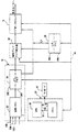
図1を参照しながら述べると、カラー・フロー及びグレイ・スケール・イメージング・システムの基本的な信号処理系は超音波トランスデューサ・アレイ2を含んでおり、超音波トランスデューサ・アレイ2は起動されて、長さPのトーン・バーストで構成されているパルス系列を送信する。トーン・バーストは、典型的にはキロヘルツの範囲にあるパルス繰り返し周波数(PRF)で繰り返しファイアリングされる。このパルス系列は、バースト長Pを含めて、カラー・フロー処理とBモード処理とで異なっている。カラー・フロー・イメージングの場合には、Pは4周期〜8周期であり得、トーン・バーストは同じ送信特性で同じ送信焦点位置に集束している。
【0010】
同じ送信焦点位置に集束している一連のカラー・フロー送信ファイアリングを「パケット」と呼ぶ。各々の送信ビームは、走査されている物体を通して伝播し、物体内の超音波散乱体によって反射される。
【0011】
帰投したRF信号は、トランスデューサ素子によって検出されて、ビームフォーマ4内に設けられているそれぞれの受信チャネルによって受信される。ビームフォーマは、遅延されたチャネル・データを加算して、ビーム加算された信号として出力し、この信号は復調器6によって同相及び直角位相(I/Q)の信号成分へ復調される。復調器6からのBモードのI出力及びQ出力は、グレイ・スケールBモード処理のために中間プロセッサ8Gへ送信され、復調器6からのカラー・フローのI出力及びQ出力は、カラー処理のために中間プロセッサ8Cへ送信される。
【0012】
図2は、中間プロセッサ8Cを示している。復調器6からのI/Q信号成分はコーナ・ターナ・メモリ7に記憶される。コーナ・ターナ・メモリ7の目的は、インタリーブされている可能性のあるファイアリングからのデータをバッファリングして、所与のレンジのセルにおいて複数のファイアリングにわたる点のベクトルとしてデータを出力することである。データは「ファスト・タイム(fast time) 」式で受信され、すなわち各回のファイアリング毎に(ベクトルに沿って)レンジを下降する順に受信される。コーナ・ターナ・メモリの出力は、「スロー・タイム(slow time) 」式で再配列され、すなわち各々のレンジ・セル毎にファイアリング順に再配列される。結果として得られた「スロー・タイム」式I/Q信号サンプルは、ウォール・フィルタ9を通過し、ウォール・フィルタ9は静止した組織又は極めて低速で運動する組織に対応するあらゆるクラッタを除去する。次いで、フィルタ処理後の出力は、パラメータ推定器11へ供給され、パラメータ推定器11は、レンジ・セル情報を中間的な自己相関パラメータN、D及びR(O)へ変換する。N及びDは、自己相関方程式の分子及び分母であり、次のように示される。
【0013】
【数1】

ここで、Ii 及びQi は、ファイアリングiについての復調後のベースバンド化された入力データであり、Mはパケット内のファイアリングの数である。R(O)は、パケット内のファイアリングの数にわたる有限の和として近似され、次の通りになる。
【0015】
【数2】
プロセッサは、N及びDを各々のレンジ・セル毎の大きさ及び位相へ変換する。用いられる方程式は次の通りである。
【0017】
【数3】
パラメータ推定器は、これらの大きさ及び位相の値を処理してパワー、速度、及び乱流又は分散の推定値を表わす値を有する信号へ変換し、それぞれ導体11A、11B及び11C上に送信する。位相は平均ドプラ周波数を算出するのに用いられ、平均ドプラ周波数は下に示すように速度に比例している。また、R(O)及び|R(T)|(大きさ)は乱流を推定するのに用いられる。
【0019】
ヘルツ単位での平均ドプラ周波数は、N及びDの位相、並びにTからのパルス繰り返しから得られる。
【0020】
【数4】
平均速度は、下記のドプラ・シフト方程式を用いて算出される。流れの方向とサンプリングの方向との間の角度であるθは未知であるので、cosθは1.0であるものと仮定される。
【0022】
【数5】
好ましくは、パラメータ推定器は、平均ドプラ周波数を中間的な出力として算出する訳ではなく、ルックアップ・テーブルを用いてプロセッサの位相出力から直接ベクトルvを算出する。
【0024】
乱流は、平均ドプラ周波数の分散の2次級数展開として時間領域において算出することができる。乱流の時間領域表現は、ゼロ遅れ(zero-lag)及び1次遅れ(one-lag) の自己相関関数R(O)及びR(T)をそれぞれ算出することを含んでいる。正確な自己相関関数は、パケット内のファイアリングの数の範囲内の既知のデータにわたる有限の和によって近似される。
【0025】
【数6】
平均値信号θ(R(T))は、流動する反射体の平均ドプラ周波数シフトの推定値であり、平均血流速度に比例している。分散信号σ2 は、ベースバンド・エコー信号の流れ信号成分の周波数の広がりを示している。層流は極めて狭い範囲の速度を有する一方で、乱流は多くの速度の混成であるので、分散の値は流れの乱れを示すものとなる。流動する反射体からの信号の強度を示すためには、信号R(O)が、ドプラ・シフトした流れ信号中における帰投したパワーの量を示している。
【0027】
導体11A上の信号パワーは、様々な群のデータ圧縮曲線に従ってデータを圧縮するデータ圧縮モジュール13を通過する。異なる走査応用については異なる群の曲線を提供することができる。例えば、1つの群の曲線は腎臓走査用に提供され、他の1つの群の曲線は頚動脈走査用に提供される。典型的には、1つの群につき約3つの曲線が存在する。信号のダイナミック・レンジは、データ圧縮に用いられる曲線に従って変化する。各々の群に属する曲線は、ダイナミック・レンジが増大する順に配列されている。利用者が走査応用を選択すると、コントローラ26が既定の曲線を設定する。ダイナミック・レンジは、表示装置18上で作成される強度又はルーメンの範囲を制御する。
【0028】
図3について説明する。グレイ・スケールBモード中間プロセッサ8Gは、量(I2 +Q2 )1/2 を算出することによりビーム加算された受信信号の包絡線を形成する包絡線検波器10を含んでいる。信号の包絡線は、対数圧縮(図3のブロック12)等の何らかの更なるBモード処理を施されて表示データを形成し、表示データがスキャン・コンバータ14(図1)へ出力される。
【0029】
再び図1を見ると、カラー・フロー推定値及びグレイ・スケール表示データがスキャン・コンバータ14へ送られると、スキャン・コンバータ14はこれらのデータをビデオ表示用のXYフォーマットへ変換する。走査変換(スキャン・コンバート)されたフレームは、ビデオ・プロセッサ16へ渡され、ビデオ・プロセッサ16は基本的には、ビデオ・データをビデオ表示のために表示カラー・マップ及びグレイ・スケール画像フレームへマッピングする。次いで、画像フレームは、ビデオ・モニタ18へ送られて表示される。典型的には、カラー画像の場合には、速度若しくはパワーのいずれかが単独で表示されるか、又は速度がパワー若しくは乱流のいずれかと組み合わされて表示される。システム制御は、ホスト・コンピュータ(図示されていない)に集中化されており、ホスト・コンピュータは操作者インタフェイス(例えばキーボード)を介して操作者入力を受け取って、様々なサブシステムを制御する。
【0030】
一般的には、Bモード・グレイ・スケール画像の場合には、表示データはスキャン・コンバータ14によってビデオ表示用のXYフォーマットへ変換される。走査変換されたフレームは、ビデオ・プロセッサ16へ渡され、ビデオ・プロセッサ16は、ビデオ・データをビデオ表示用のグレイ・スケール又はグレイ・マップへマッピングする。次いで、グレイ・スケール画像フレームは、ビデオ・モニタ18へ送られて表示される。
【0031】
ビデオ・モニタ18によって表示される画像は、その各々が表示におけるそれぞれのピクセルの強度又は輝度を指示しているようなデータから成る画像フレームから形成されている。画像フレームは、各々の強度データがピクセル輝度を指示する8ビットの2進数であるような、例えば256×256のデータ・アレイを含み得る。表示モニタ18上の各々のピクセルの輝度は、周知の態様で、データ・アレイ内の各ピクセルに対応する要素の値を読み込むことにより絶えず更新されている。各々のピクセルは、呼び掛け(interrogating) した超音波パルスに応答するそれぞれのサンプル空間の後方散乱体断面積と、用いられているグレイ・マップとの関数である強度値を有する。
【0032】
図4について説明する。システム制御は、マスタ・コントローラ又はホスト・コンピュータ26に集中化されており、マスタ・コントローラ26は操作者インタフェイス(図示されていない)を介して操作者入力を受け取って、様々なサブシステムを制御する。マスタ・コントローラ26はまた、システムのタイミング信号及び制御信号を発生する。マスタ・コントローラ26は、中央処理ユニット(CPU)30と、ランダム・アクセス・メモリ32とを含んでいる。CPU30にデータを入力するためにはキーボード29が用いられる。CPU30は、取得された生データに基づいてグレイ・マップ及びカラー・マップを構築するのに用いられるルーチンを記憶しているリード・オンリ・メモリを内部に組み込んでいる。
【0033】
スキャン・コンバータ14は、音線メモリ22と、XYメモリ24とを含んでいる。音線メモリ22内に極座標(R−θ)のセクタ・フォーマットで記憶されているBモード強度データ及びカラー・モード強度データは、適当にスケーリングされたデカルト座標のピクセル表示データへ変換され、変換後のデータはXYメモリ24に記憶される。カラー・データはメモリ位置24Cに記憶され、グレイ・スケール・データはメモリ位置24Gに記憶される。走査変換されたフレームはビデオ・プロセッサ16へ渡されて、ビデオ・プロセッサ16はデータをビデオ表示用のグレイ・マップへマッピングする。次いで、グレイ・スケール画像フレームは、ビデオ・モニタへ送られて表示される。
【0034】
音波サンプル・データの連続したフレームは、先入れ先出し方式でシネ・メモリ28に記憶される。カラー・フレームはメモリ位置28Cに記憶され、グレイ・スケール・フレームはメモリ位置28Gに記憶される。カラーの関心領域においては、表示ピクセルに対応するカラー・データの各々のワード毎に、該ピクセルに対応するBモード・グレイ・スケール・データの対応するワードが存在している。シネ・メモリは、バックグラウンドで稼働する循環的な画像バッファのようなものであり、音波サンプル・データを絶えず取り込んで、実時間で利用者に対して表示する。利用者がシステムをフリーズさせると、利用者は、シネ・メモリに以前に取り込まれている音波サンプル・データを見ることができるようになる。
【0035】
CPU30は、システム制御バス34を介してXYメモリ24及びシネ・メモリ28を制御する。具体的には、CPU30は、XYメモリ24からビデオ・プロセッサ16及びシネ・メモリ28への生データの流れを制御すると共に、シネ・メモリからビデオ・プロセッサ16及びCPU26自体への生データの流れを制御する。CPUはまた、グレイ・マップ及びカラー・マップをビデオ・プロセッサにロードする。
【0036】
画像フレームは、連続的にシネ・メモリ28に収集される。シネ・メモリ28は、単一画像閲覧及び多数画像ループ閲覧のための常駐のディジタル画像記憶容量、並びに様々な制御機能を提供している。単一画像のシネ再生時に表示される関心領域は、画像取得時に用いられている領域である。シネ・メモリはまた、画像をマスタ・コントローラ26を介してディジタル保管装置(図示されていない)へ転送するためのバッファの役割も果たしている。
【0037】
CPU30はランダム・アクセス・メモリを有しており、生データ・ヒストグラムを取得し、新たなグレイ・マップの入力範囲の両端の点を決定し、新たなグレイ・マップの入力範囲の両端の点に基づいて新たなグレイ・マップを構築し、新たなグレイ・マップの傾き及びゲインを所定の傾きの限度及びゲインの限度と比較して、いずれかの限度を上回っていた場合には一方又は両方の限度に従うように新たなグレイ・マップを再構築するのに用いられるルーチンを記憶している。
【0038】
本発明の好適実施例によれば、超音波画像のコントラストは、調節されたグレイ・マップ値及びカラー・マップ値への生の音波サンプル・データのマッピングを形成することにより、マスタ・コントローラ26によって調節される。先ず、マスタ・コントローラ26は、XYメモリ24又はシネ・メモリ28から生データの1つ又はこれよりも多い画像フレームを検索し、この生データをメモリ32に記憶する。次いで、CPU30は、検索された生データの画像フレームについて多数の所定の範囲又はビンの各々の範囲内にある振幅又は値を有する音波サンプルの数のヒストグラムを蓄積する。
【0039】
好適実施例によれば、カラー・フロー自動表示処理モードは、キーボード29(図4)を介して利用者によって開始され、次いで、走査状況が変化するのに伴って、後処理用パラメータの更新のために利用者によってあらためて開始されるか、又は一挙にオフにされる。
【0040】
好適実施例によれば、上述のBモード・グレイ・スケール及びカラー・フローの走査データを用いて、カラー表示の画質を最適化する。コントローラ26によってカラー・フロー・モード及び/又はBモードについて、複合的なヒストグラム(幾つかのフレームにわたるデータのヒストグラム)及び/又は単一フレームのヒストグラムをシネ・メモリ28のデータから構築する。次いで、これらのヒストグラムの結果に対して、特定の走査状況又は応用について如何にして様々なパラメータを適切に調節するかを決定するアルゴリズムをコントローラ26によって適用する。
【0041】
これらのアルゴリズムは次の通りである。
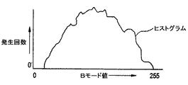
Bモード用のカレントのプリセットのダイナミック・レンジ設定及び圧縮曲線を用いて、走査データの振幅を表わすBモード・グレイ・スケール・データの単一のフレームをシネ・メモリ28Gから収集する。コントローラ26は、図5のように表わされ得るデータの第1の複合的ヒストグラムを生成するアルゴリズムを実行する。
【0042】
上のステップの代替として、コントローラ26は、あらゆるダイナミック・レンジ圧縮を適用する前に走査データのヒストグラムを形成するか、又はデータを圧縮しないでヒストグラムを形成する。
【0043】
キーボードを操作することにより、利用者は、パワー・データを用いるカラー・フロー・モード及び別個に速度データを用いるカラー・フロー・モードを入力することができる。これらのモードでは、B/カラー優先順位閾値が存在しており、この閾値は、キーボード29上のソフトキー・メニューから利用者が選択可能であり、また、255の最大Bモードグレイ・スケール値のx%にプリセットされている。閾値は、例えば端子31及び33において受け取られる。カラー・モードの関心領域(ROI)内のあらゆるピクセルについて、Bモード・ピクセル値が選択されたB/カラー優先順位閾値を上回っている場合には、該ピクセルについてはBモード値が表示される。その他の場合には、存在しているならば対応するカラー・ピクセル値が表示される。
【0044】
本アルゴリズムは、シネ・メモリ28GからBモード・データ・ワードの単一のフレームを取り込んで、カラーROI内で最大の値を有するn%のBモード・ワードを検出する。例えばnが5%である場合には、カラーROI内のメモリ28Gの全てのBモード・ワードが読み込まれ、これらのワードのうち最大値を有する5%が1つの組として識別される。以上のステップは好ましくは、図5と関連して記載したようにして算出されたヒストグラムを用いて行われる。次いで、B/カラー優先順位閾値をこの組の平均のx%に設定する。ここで、xは現在選択されているB/カラー優先順位閾値百分率である。次いで、自動的に調節された閾値を用いて、前述した態様で表示を形成する。
【0045】
ここに述べた実施例は、パワー閾値、ウォール・フィルタ遮断周波数、ベースライン・シフト及び速度スケール等のその他の後処理パラメータを自動的に調節するように拡張することもできる。シネ・データのBフレーム及び/又はカラー・フロー・フレームを収集するという同じ基本的発想が適用され、関連するアルゴリズムを用いて、特定の後処理パラメータを如何に調節するかを正確に決定する。
【0046】
以上の好適実施例は、説明の目的のために開示された。当業者には、本発明の概念の変形及び改変は容易に明らかとなろう。これらのような全ての変形及び改変は、特許請求の範囲によって包含されているものとする。
【図面の簡単な説明】
【図1】 従来のカラー・フロー及びBモード超音波イメージング・システムの信号処理系を示す概略ブロック図である。
【図2】 図1に示す中間プロセッサのカラー・フロー装置を示す概略ブロック図である。
【図3】 図1に示す中間プロセッサのBモード装置を示す概略ブロック図である。
【図4】 図1に示すシステムの各部の更なる細部を示す概略ブロック図である。
【図5】 図4に示すメモリに記憶されるデータの可能な形態を示すグラフである。
【符号の説明】
2 超音波トランスデューサ・アレイ
8C カラー処理用中間プロセッサ
8G グレイ・スケールBモード処理用中間プロセッサ
26 マスタ・コントローラ
34 システム制御バス
31、33 閾値受取用端子[0001]
BACKGROUND OF THE INVENTION
The present invention relates generally to ultrasonic color flow Doppler imaging of fluid flow fields. More specifically, the present invention relates to a method and apparatus for improving the display of such imaging.
[0002]
BACKGROUND OF THE INVENTION
Ultrasonic scanners that detect blood flow based on the Doppler effect are well known. These systems operate by activating an ultrasonic transducer array to transmit ultrasonic waves into the object and to receive ultrasonic echoes backscattered from the object. When measuring blood flow characteristics, the returned ultrasound is compared with a frequency reference to determine the frequency shift imparted to the returning wave by a flowing scatterer such as blood cells. This frequency shift, that is, the phase shift becomes the blood flow velocity. Blood velocity is calculated by measuring the phase shift from firing to firing at a specific range gate.
[0003]
The change or shift in the frequency of the backscattered wave increases when blood flow flows toward the transducer and decreases when blood flows away from the transducer. A color flow image is formed by superimposing a color image of the velocity of a moving substance such as blood on a B-mode image of a black and white anatomical structure. Typically, color flow mode displays hundreds of adjacent sample spaces simultaneously, all of which are superimposed on the B-mode image to represent the velocity of each sample space. Are color coded.
[0004]
Typically, a color flow processor estimates blood flow velocity, blood flow power, and blood flow variance. Typically, color flow data is used to correct the color of the region of interest on the display screen. The user selects the data format used for display. Typically available modes are power only mode, speed only mode, or a combination of speed and dispersion.
[Patent Document 1]
German published patent 198 19 800
[Patent Document 2]
US Pat. No. 5,235,984
[Patent Document 3]
Japanese open patent JP-A H06-007353
[Patent Document 4]
US Pat. No. 5,347,600
[Patent Document 5]
Japanese published patent special table H04-506437
[Patent Document 6]
US Pat. No. 5,718,229
[Patent Document 7]
US Pat. No. 5,732,705
[Patent Document 8]
Japanese open patent JP-A H09-075348
[Patent Document 9]
US Pat. No. 5,735,977
[Patent Document 10]
Japanese published patent JP-A H10-309278
[Patent Document 11]
US Pat. No. 5,993,392
[Patent Document 12]
US Pat. No. 6,017,309
[Patent Document 13]
Japanese Patent Open Patent 2002-534183
[0005]
[Problems to be solved by the invention]
In current ultrasound scanners, various color flow display parameters are fixed in a state where selection by the user is impossible, or when a user takes action when preset to some specific setting. Either one parameter can be changed at a time. This limits image quality and user productivity for any given application and scanning situation. There is a need for a scanner that can automatically adjust all of these same parameters simultaneously to optimize the image associated with the color flow display for a particular scanning situation, thereby increasing user productivity.
[0006]
In operation in color flow power mode and color flow speed mode, known ultrasound scanners provide a B / color priority threshold, which is a softkey menu on the scanner user console. The user can select from. This threshold can be set by the user as various percentages of the maximum B-mode gray scale value. For any pixel in the color mode region of interest (ROI), if the B-mode pixel value is above the selected B / color priority threshold, the B-mode value is displayed for that pixel. . In other cases, if present, the corresponding color pixel value is displayed. However, the actual B-mode data maximum can vary over a wide range. As a result, the threshold is often less than optimal. Therefore, there is a need for a color flow ultrasound scanner that can automatically adjust the B / color priority threshold according to actual B-mode data.
[0007]
[Means for Solving the Problems]
The present invention relates to an ultrasound imaging system that generates a color flow signal in response to an ultrasound signal backscattered from a subject and generates an image signal based on the amplitude of the ultrasound signal backscattered from the subject. Useful for. According to this aspect of the invention, the image is displayed in response to the color flow signal, preferably by receiving a threshold signal from a control operated by the user. A first set of data words in response to the color flow signal is preferably stored in the digital memory, and a second set of data words in response to the image signal is stored. A characteristic value corresponding to at least one characteristic of the second set of data words is preferably determined by the logic unit. The threshold value is changed in response to the characteristic value. Depending on the predetermined relationship between the changed threshold and the values of the first and second sets of data words, a data word is selected from the first and second sets, preferably by a logic unit. The A color flow image is displayed in response to the selected data word.
[0008]
By using the above method, the display of the ultrasonic scanner can be automatically adjusted for optimal visual image formation.
[0009]
DETAILED DESCRIPTION OF THE INVENTION
Referring to FIG. 1, the basic signal processing system of the color flow and gray scale imaging system includes an ultrasonic transducer array 2, which is activated, A pulse sequence composed of tone bursts of length P is transmitted. Tone bursts are fired repeatedly at a pulse repetition frequency (PRF) typically in the kilohertz range. This pulse sequence, including the burst length P, differs between color flow processing and B-mode processing. In the case of color flow imaging, P can be between 4 and 8 periods, and the tone bursts are focused on the same transmit focal position with the same transmission characteristics.
[0010]
A series of color flow transmit firings that converge at the same transmit focal position is called a “packet”. Each transmit beam propagates through the object being scanned and is reflected by ultrasonic scatterers within the object.
[0011]
The returned RF signal is detected by the transducer element and received by each receiving channel provided in the beam former 4. The beamformer adds the delayed channel data and outputs a beam-added signal, which is demodulated by the demodulator 6 into in-phase and quadrature (I / Q) signal components. The B mode I and Q outputs from the demodulator 6 are sent to the
[0012]
FIG. 2 shows the
[0013]
[Expression 1]
Where Ii And Qi Is the demodulated baseband input data for firing i, and M is the number of firings in the packet. R (O) is approximated as a finite sum over the number of firings in the packet and becomes:
[0015]
[Expression 2]
The processor converts N and D to the size and phase for each range cell. The equations used are as follows:
[0017]
[Equation 3]
The parameter estimator processes these magnitude and phase values and converts them into signals having values representing power, velocity, and turbulence or dispersion estimates and transmits them on
[0019]
The average Doppler frequency in Hertz is obtained from the N and D phases and the pulse repetition from T.
[0020]
[Expression 4]
The average speed is calculated using the following Doppler shift equation. Since θ, which is the angle between the direction of flow and the direction of sampling, is unknown, cos θ is assumed to be 1.0.
[0022]
[Equation 5]
Preferably, the parameter estimator does not calculate the average Doppler frequency as an intermediate output, but directly calculates the vector v from the phase output of the processor using a look-up table.
[0024]
The turbulent flow can be calculated in the time domain as a quadratic series expansion of the variance of the average Doppler frequency. The time domain representation of turbulence involves calculating zero-lag and one-lag autocorrelation functions R (O) and R (T), respectively. The exact autocorrelation function is approximated by a finite sum over the known data within the number of firings in the packet.
[0025]
[Formula 6]
The average value signal θ (R (T)) is an estimated value of the average Doppler frequency shift of the flowing reflector, and is proportional to the average blood flow velocity. Dispersion signal σ2 Indicates the frequency spread of the flow signal component of the baseband echo signal. While laminar flow has a very narrow range of velocities, turbulence is a hybrid of many velocities, so the value of dispersion is indicative of flow turbulence. To indicate the strength of the signal from the flowing reflector, the signal R (O) indicates the amount of power returned in the Doppler shifted flow signal.
[0027]
The signal power on conductor 11A passes through a
[0028]
With reference to FIG. The gray scale B-mode
[0029]
Referring again to FIG. 1, when color flow estimates and gray scale display data are sent to the
[0030]
In general, in the case of a B-mode gray scale image, the display data is converted by the
[0031]
The image displayed by the
[0032]
FIG. 4 will be described. System control is centralized in a master controller or host computer 26, which receives operator input via an operator interface (not shown) and controls various subsystems. To do. The master controller 26 also generates system timing and control signals. The master controller 26 includes a central processing unit (CPU) 30 and a
[0033]
The
[0034]
Consecutive frames of sonic sample data are stored in the
[0035]
The CPU 30 controls the
[0036]
Image frames are continuously collected in the
[0037]
The CPU 30 has a random access memory, acquires a raw data histogram, determines points at both ends of the new gray map input range, and sets points at both ends of the new gray map input range. Build a new gray map based on it, compare the slope and gain of the new gray map with the limits of the predetermined slope and gain, and if either limit is exceeded, either or both Stores routines used to reconstruct new gray maps to comply with limits.
[0038]
According to a preferred embodiment of the present invention, the contrast of the ultrasound image is adjusted by the master controller 26 by forming a mapping of the raw sonic sample data to the adjusted gray map values and color map values. Adjusted. First, the master controller 26 retrieves one or more image frames of raw data from the
[0039]
According to the preferred embodiment, the color flow automatic display processing mode is initiated by the user via the keyboard 29 (FIG. 4) and then the post-processing parameters are updated as the scanning situation changes. It is either started again by the user or turned off at once.
[0040]
According to a preferred embodiment, the B-mode gray scale and color flow scan data described above is used to optimize the color display image quality. The controller 26 builds a composite histogram (histogram of data over several frames) and / or a single frame histogram from the data in the
[0041]
These algorithms are as follows.
A single frame of B-mode gray scale data representing the amplitude of the scan data is collected from
[0042]
As an alternative to the above steps, the controller 26 forms a histogram of the scan data before applying any dynamic range compression, or forms a histogram without compressing the data.
[0043]
By operating the keyboard, the user can enter a color flow mode using power data and a color flow mode using velocity data separately. In these modes, there is a B / color priority threshold, which can be selected by the user from a softkey menu on the keyboard 29 and has a maximum B-mode gray scale value of 255. It is preset to x%. The threshold value is received at
[0044]
The algorithm takes a single frame of B-mode data words from
[0045]
The described embodiment can also be extended to automatically adjust other post-processing parameters such as power threshold, wall filter cutoff frequency, baseline shift and velocity scale. The same basic idea of collecting B frames and / or color flow frames of cine data is applied, and an associated algorithm is used to determine exactly how to adjust certain post-processing parameters.
[0046]
The foregoing preferred embodiments have been disclosed for purposes of illustration. Variations and modifications of the inventive concept will be readily apparent to those skilled in the art. All such variations and modifications are intended to be encompassed by the claims.
[Brief description of the drawings]
FIG. 1 is a schematic block diagram showing a signal processing system of a conventional color flow and B-mode ultrasound imaging system.
FIG. 2 is a schematic block diagram showing a color flow device of the intermediate processor shown in FIG.
3 is a schematic block diagram showing a B-mode device of the intermediate processor shown in FIG. 1. FIG.
4 is a schematic block diagram showing further details of each part of the system shown in FIG. 1;
FIG. 5 is a graph showing possible forms of data stored in the memory shown in FIG.
[Explanation of symbols]
2 Ultrasonic transducer array
Intermediate processor for 8C color processing
Intermediate processor for 8G gray scale B-mode processing
26 Master controller
34 System control bus
31, 33 Threshold receiving terminal
Claims (12)
閾値を表す閾値信号を受け取るように接続されている端子(31)と、
前記カラー・フロー信号に応じた第1の組のデータ・ワードを記憶すると共に、前記Bモード画像信号に応じた第2の組のデータ・ワードを記憶するように接続されているメモリ(32)と、
前記第2の組のデータ・ワードの少なくとも1つの特性に対応する特性値を決定し、該特性値に応答して前記閾値を変更すると共に、該変更後の閾値と前記第1の組のデータ・ワード及び第2の組のデータ・ワードの値との間の所定の関係に応じて、前記第1及び第2の組のデータ・ワードから、特定のデータ・ワードを選択するように接続されている論理ユニット(26)と、
前記選択されたデータ・ワードに応答して、カラー・フロー画像を表示するように接続されている表示装置(18)と、
を備え、
前記閾値はB/カラー優先順位信号であり、前記第1の組のデータ・ワードのデータはカラーフロー画像データを表し、前記第2の組のデータ・ワードのデータはBモード画像データを表すものである場合において、
この超音波画像処理表示装置の前記論理ユニット(26)は、
前記特定のデータ・ワードを前記第1の組のデータ・ワードか第2の組のデータ・ワードから選択し、
前記Bモード画像データ値が前記変更されたB/カラー優先順位閾値を超えるときはBモード画像データを選択し、
前記Bモード画像データ値が前記変更されたB/カラー優先順位閾値を超えないきはカラーフロー画像データを選択することを特徴とする超音波画像処理表示装置。Together in response to ultrasound signals backscattered from the subject to generate a color flow signal and B-mode image signals, an ultrasound image processing in response to display an image on the ultrasonic image processing and displaying apparatus wherein color flow signals A display device,
A terminal (31) connected to receive a threshold signal representative of the threshold;
A memory (32) connected to store a first set of data words in response to the color flow signal and to store a second set of data words in response to the B-mode image signal When,
Determining a characteristic value corresponding to at least one characteristic of the second set of data words, changing the threshold in response to the characteristic value, and changing the threshold and the first set of data; words and according to a predetermined relationship between the value of the second set of data words from said first and second set of data words, coupled to select a particular data word A logical unit (26) ,
A display device (18) connected to display a color flow image in response to the selected data word;
Equipped with a,
The threshold is a B / color priority signal, the data in the first set of data words represents color flow image data, and the data in the second set of data words represents B-mode image data In the case
The logical unit (26) of the ultrasonic image processing display device includes:
Selecting the particular data word from the first set of data words or the second set of data words;
When the B-mode image data value exceeds the changed B / color priority threshold, select B-mode image data;
An ultrasonic image processing display apparatus , wherein color flow image data is selected when the B-mode image data value does not exceed the changed B / color priority threshold .
閾値を表す閾値信号を受け取る工程と、
前記カラー・フロー信号に応じた第1の組のデータ・ワードを記憶すると共に、前記Bモード画像信号に応じたデータ・ワードの第2の組を記憶する工程と、
前記第2の組のデータ・ワードの少なくとも1つの特性に対応する特性値を決定する工程と、
該特性値に応答して前記閾値を変更する工程と、
該変更後の閾値と前記第1の組のデータ・ワード及び前記第2の組のデータ・ワードの値との間の所定の関係に応じて、前記第1の組のデータ・ワード及び第2の組のデータ・ワードから特定のデータ・ワードを選択する選択工程と、
該選択されたデータ・ワードに応答してカラー・フロー画像を表示する工程と、を有している超音波画像処理方法であって、
前記閾値はB/カラー優先順位信号であり、
前記第1の組のデータ・ワードのデータはカラーフロー画像データを表し、前記第2の組のデータ・ワードのデータはBモード画像データを表すものである場合において、
前記選択工程は、
前記特定のデータ・ワードを前記第1の組のデータ・ワードか第2の組のデータ・ワードから選択し、
前記Bモード画像データ値が前記変更されたB/カラー優先順位閾値を超えるときはBモード画像データを選択し、
前記Bモード画像データ値が前記変更されたB/カラー優先順位閾値を超えないきはカラーフロー画像データを選択する、
ことを特徴とする超音波画像処理方法。 Ultrasonic image processing method for displaying an image in response to a color flow signal in an ultrasonic imaging system that generates a color flow signal and a B-mode image signal in response to an ultrasonic signal backscattered from a subject Because
Receiving a threshold signal representative of the threshold;
Storing a first set of data words in response to the color flow signal and storing a second set of data words in response to the B-mode image signal;
Determining a characteristic value corresponding to at least one characteristic of the second set of data words;
Changing the threshold in response to the characteristic value;
According to a predetermined relationship between the threshold and the first set of data words and the value of the second set of data words after the change, the first set of data words and a second A selection step of selecting a specific data word from the set of data words ;
An ultrasonic image processing method has a step of displaying a color flow image in response to the selected data word, and
The threshold is a B / color priority signal;
In the case where the data of the first set of data words represents color flow image data and the data of the second set of data words represents B-mode image data,
The selection step includes
Selecting the particular data word from the first set of data words or the second set of data words;
When the B-mode image data value exceeds the changed B / color priority threshold, select B-mode image data;
If the B-mode image data value does not exceed the modified B / color priority threshold, select color flow image data;
An ultrasonic image processing method.
Applications Claiming Priority (3)
| Application Number | Priority Date | Filing Date | Title |
|---|---|---|---|
| US09/224,450 US6120451A (en) | 1998-12-31 | 1998-12-31 | Ultrasound color flow display optimization by adjustment of threshold |
| US09/224,450 | 1998-12-31 | ||
| PCT/US1999/028919 WO2000041003A1 (en) | 1998-12-31 | 1999-12-06 | Ultrasound color flow display optimization by adjustment of threshold |
Publications (3)
| Publication Number | Publication Date |
|---|---|
| JP2002534188A JP2002534188A (en) | 2002-10-15 |
| JP2002534188A5 JP2002534188A5 (en) | 2009-06-18 |
| JP4424856B2 true JP4424856B2 (en) | 2010-03-03 |
Family
ID=22840743
Family Applications (1)
| Application Number | Title | Priority Date | Filing Date |
|---|---|---|---|
| JP2000592668A Expired - Fee Related JP4424856B2 (en) | 1998-12-31 | 1999-12-06 | Optimization method of ultrasonic color flow display by adjusting threshold |
Country Status (4)
| Country | Link |
|---|---|
| US (1) | US6120451A (en) |
| EP (1) | EP1060411A1 (en) |
| JP (1) | JP4424856B2 (en) |
| WO (1) | WO2000041003A1 (en) |
Families Citing this family (13)
| Publication number | Priority date | Publication date | Assignee | Title |
|---|---|---|---|---|
| US6500125B1 (en) * | 2000-03-30 | 2002-12-31 | Ge Medical Systems Global Technology Company, Llc | Ultrasound b/color priority threshold calculation |
| US6652462B2 (en) * | 2001-06-12 | 2003-11-25 | Ge Medical Systems Global Technology Company, Llc. | Ultrasound display of movement parameter gradients |
| US7245746B2 (en) * | 2001-06-12 | 2007-07-17 | Ge Medical Systems Global Technology Company, Llc | Ultrasound color characteristic mapping |
| US6579240B2 (en) * | 2001-06-12 | 2003-06-17 | Ge Medical Systems Global Technology Company, Llc | Ultrasound display of selected movement parameter values |
| US20030045797A1 (en) * | 2001-08-28 | 2003-03-06 | Donald Christopher | Automatic optimization of doppler display parameters |
| US7887484B2 (en) * | 2005-08-12 | 2011-02-15 | Siemens Medical Solutions Usa, Inc. | Automatic velocity scale identification for medical diagnostic ultrasound |
| JP5236655B2 (en) * | 2006-10-13 | 2013-07-17 | コーニンクレッカ フィリップス エレクトロニクス エヌ ヴィ | 3D ultrasound color flow imaging using gray scale inversion |
| CN103204825B (en) | 2012-01-17 | 2015-03-04 | 上海科州药物研发有限公司 | Benzothiazole compounds as protein kinase inhibitors, and preparation method and application thereof |
| EP2989986B1 (en) * | 2014-09-01 | 2019-12-18 | Samsung Medison Co., Ltd. | Ultrasound diagnosis apparatus and method of operating the same |
| WO2016072208A1 (en) * | 2014-11-05 | 2016-05-12 | 古野電気株式会社 | Detection information display device, radar device, sonar device, fish detection device, and detection information display method |
| AU2015380696B2 (en) | 2015-01-26 | 2018-09-27 | Halliburton Energy Services, Inc. | Traceable micro-electro-mechanical systems for use in subterranean formations |
| BR112017015484A2 (en) | 2015-02-27 | 2018-01-30 | Halliburton Energy Services Inc | system for measuring treatment fluid rheology and method for monitoring treatment fluid rheology |
| JP6745209B2 (en) * | 2016-12-28 | 2020-08-26 | 株式会社日立製作所 | Ultrasonic diagnostic equipment |
Family Cites Families (10)
| Publication number | Priority date | Publication date | Assignee | Title |
|---|---|---|---|---|
| JPH01310648A (en) * | 1988-06-08 | 1989-12-14 | Toshiba Corp | Ultrasonic blood circulation imaging device |
| US5065447A (en) * | 1989-07-05 | 1991-11-12 | Iterated Systems, Inc. | Method and apparatus for processing digital data |
| US5235984A (en) * | 1992-03-30 | 1993-08-17 | Hewlett-Packard Company | On-line acoustic densitometry tool for use with an ultrasonic imaging system |
| US5357965A (en) * | 1993-11-24 | 1994-10-25 | General Electric Company | Method for controlling adaptive color flow processing using fuzzy logic |
| JP3833282B2 (en) * | 1994-06-24 | 2006-10-11 | 株式会社東芝 | Ultrasonic diagnostic equipment |
| JPH0975348A (en) * | 1995-09-12 | 1997-03-25 | Toshiba Corp | Ultrasonic diagnostic equipment |
| US5718229A (en) * | 1996-05-30 | 1998-02-17 | Advanced Technology Laboratories, Inc. | Medical ultrasonic power motion imaging |
| US5993392A (en) * | 1996-11-05 | 1999-11-30 | Atl Ultrasound, Inc. | Variable compression of ultrasonic image data with depth and lateral scan dimensions |
| US5735797A (en) * | 1996-12-30 | 1998-04-07 | General Electric Company | Method and apparatus for combining topographic flow power imagery with a B-mode anatomical imagery |
| US6017309A (en) * | 1998-12-31 | 2000-01-25 | Washburn; Michael J. | Ultrasound color flow display optimization by adjusting color maps |
-
1998
- 1998-12-31 US US09/224,450 patent/US6120451A/en not_active Expired - Lifetime
-
1999
- 1999-12-06 EP EP99967215A patent/EP1060411A1/en not_active Withdrawn
- 1999-12-06 WO PCT/US1999/028919 patent/WO2000041003A1/en active Application Filing
- 1999-12-06 JP JP2000592668A patent/JP4424856B2/en not_active Expired - Fee Related
Also Published As
| Publication number | Publication date |
|---|---|
| JP2002534188A (en) | 2002-10-15 |
| EP1060411A1 (en) | 2000-12-20 |
| US6120451A (en) | 2000-09-19 |
| WO2000041003A1 (en) | 2000-07-13 |
Similar Documents
| Publication | Publication Date | Title |
|---|---|---|
| US6126605A (en) | Ultrasound color flow display optimization by adjusting dynamic range | |
| US6017309A (en) | Ultrasound color flow display optimization by adjusting color maps | |
| US6162176A (en) | Ultrasound color flow display optimization | |
| US6406430B1 (en) | Ultrasound image display by combining enhanced flow imaging in B-mode and color flow mode | |
| JP4531894B2 (en) | Method and apparatus for automatic Doppler angle estimation in ultrasound imaging | |
| JP2003501177A (en) | Simultaneous tissue and motion ultrasound diagnostic imaging | |
| JP4627366B2 (en) | Method and apparatus for motion visualization in ultrasonic flow imaging using packet data acquisition | |
| JP4424856B2 (en) | Optimization method of ultrasonic color flow display by adjusting threshold | |
| JP2002534185A (en) | Automatic spectral optimization method for Doppler ultrasound | |
| JP3251696B2 (en) | Ultrasound diagnostic equipment | |
| JPH03188841A (en) | Ultrasonic diagnostic device | |
| JPH10309278A (en) | Imaging system for speed of ultrasonic scatterer | |
| EP0524774A2 (en) | Ultrasonic doppler imaging apparatus | |
| JP4712931B2 (en) | Method and apparatus for optimal data mapping of power Doppler images | |
| JP4545940B2 (en) | Optimization method of ultrasonic color flow display by adjusting threshold using sampling | |
| US6500125B1 (en) | Ultrasound b/color priority threshold calculation | |
| US5865752A (en) | Method and apparatus for ultrasound imaging using normalized difference between successive frames | |
| JP2000149015A (en) | Method for edge enhancement of image and imaging device | |
| US6135962A (en) | Method and apparatus for adaptive filtering by counting acoustic sample zeroes in ultrasound imaging | |
| JP2938125B2 (en) | Ultrasound diagnostic equipment | |
| JP4746758B2 (en) | Ultrasound image display by combining enhanced flow imaging in B mode and color flow mode | |
| JPH06209942A (en) | Ultrasonic diagnosing device | |
| JPH08150142A (en) | Ultrasonic diagnostic device | |
| JP2602898B2 (en) | Ultrasound blood flow imaging device | |
| JP2001000435A (en) | Apparatus for ultrasonography |
Legal Events
| Date | Code | Title | Description |
|---|---|---|---|
| A621 | Written request for application examination |
Free format text: JAPANESE INTERMEDIATE CODE: A621 Effective date: 20061201 |
|
| A521 | Written amendment |
Free format text: JAPANESE INTERMEDIATE CODE: A523 Effective date: 20090417 |
|
| RD02 | Notification of acceptance of power of attorney |
Free format text: JAPANESE INTERMEDIATE CODE: A7422 Effective date: 20090417 |
|
| RD04 | Notification of resignation of power of attorney |
Free format text: JAPANESE INTERMEDIATE CODE: A7424 Effective date: 20090417 |
|
| TRDD | Decision of grant or rejection written | ||
| A01 | Written decision to grant a patent or to grant a registration (utility model) |
Free format text: JAPANESE INTERMEDIATE CODE: A01 Effective date: 20091110 |
|
| A01 | Written decision to grant a patent or to grant a registration (utility model) |
Free format text: JAPANESE INTERMEDIATE CODE: A01 |
|
| A61 | First payment of annual fees (during grant procedure) |
Free format text: JAPANESE INTERMEDIATE CODE: A61 Effective date: 20091208 |
|
| R150 | Certificate of patent or registration of utility model |
Free format text: JAPANESE INTERMEDIATE CODE: R150 |
|
| FPAY | Renewal fee payment (event date is renewal date of database) |
Free format text: PAYMENT UNTIL: 20121218 Year of fee payment: 3 |
|
| FPAY | Renewal fee payment (event date is renewal date of database) |
Free format text: PAYMENT UNTIL: 20121218 Year of fee payment: 3 |
|
| FPAY | Renewal fee payment (event date is renewal date of database) |
Free format text: PAYMENT UNTIL: 20131218 Year of fee payment: 4 |
|
| LAPS | Cancellation because of no payment of annual fees |