JP4423686B2 - Camera and development system - Google Patents
Camera and development system Download PDFInfo
- Publication number
- JP4423686B2 JP4423686B2 JP33854498A JP33854498A JP4423686B2 JP 4423686 B2 JP4423686 B2 JP 4423686B2 JP 33854498 A JP33854498 A JP 33854498A JP 33854498 A JP33854498 A JP 33854498A JP 4423686 B2 JP4423686 B2 JP 4423686B2
- Authority
- JP
- Japan
- Prior art keywords
- light emission
- unit
- release switch
- emission time
- exposure control
- Prior art date
- Legal status (The legal status is an assumption and is not a legal conclusion. Google has not performed a legal analysis and makes no representation as to the accuracy of the status listed.)
- Expired - Lifetime
Links
- 238000011161 development Methods 0.000 title description 3
- 238000012937 correction Methods 0.000 claims description 18
- 239000004973 liquid crystal related substance Substances 0.000 claims description 16
- 238000006243 chemical reaction Methods 0.000 claims description 14
- 238000001514 detection method Methods 0.000 claims description 10
- 238000003384 imaging method Methods 0.000 claims description 10
- 230000003287 optical effect Effects 0.000 claims description 10
- 238000012545 processing Methods 0.000 claims description 6
- 230000015572 biosynthetic process Effects 0.000 claims description 3
- 238000010586 diagram Methods 0.000 description 22
- 238000003780 insertion Methods 0.000 description 17
- 230000037431 insertion Effects 0.000 description 17
- 230000007246 mechanism Effects 0.000 description 8
- 238000000034 method Methods 0.000 description 4
- 230000008569 process Effects 0.000 description 4
- 230000010354 integration Effects 0.000 description 3
- 239000003990 capacitor Substances 0.000 description 2
- 238000007796 conventional method Methods 0.000 description 2
- 230000007423 decrease Effects 0.000 description 2
- 238000005516 engineering process Methods 0.000 description 2
- 230000004913 activation Effects 0.000 description 1
- 230000008859 change Effects 0.000 description 1
- 230000000994 depressogenic effect Effects 0.000 description 1
- 238000009792 diffusion process Methods 0.000 description 1
- 230000000694 effects Effects 0.000 description 1
- 230000004907 flux Effects 0.000 description 1
- 230000006870 function Effects 0.000 description 1
- 238000012544 monitoring process Methods 0.000 description 1
- 230000011514 reflex Effects 0.000 description 1
Images
Landscapes
- Exposure Control For Cameras (AREA)
- Stroboscope Apparatuses (AREA)
- Blocking Light For Cameras (AREA)
- Liquid Crystal (AREA)
- Cameras Adapted For Combination With Other Photographic Or Optical Apparatuses (AREA)
- Color Television Image Signal Generators (AREA)
- Studio Devices (AREA)
Description
【0001】
【発明が関連する技術分野】
本発明は、閃光発光器を用いたカメラ、または該カメラによって撮影されたフィルムの現像処理を行う現像システムに関する。
【0002】
【従来の技術】
従来、閃光発光器(以下SBと呼ぶ)の発光時間の違いによる色温度の変化を補正する装置としては、特許第2668984号や、特開平7−123423号公報に見られるようなものがあった。前者の装置は、電子カメラのホワイトバランス調整に関するもので、図13に示したように調光ストロボ101、積分回路102、及びホワイトバランス補正部103とを備える。その動作は、撮影時に調光ストロボ101が発光した実時間に比例する電圧値を積分回路102によって求め、その出力に従ってホワイトバランス補正部103が撮影された画像のホワイトバランスの補正を行うというものである。
【0003】
また、後者の装置はストロボ光の色温度を制御するストロボ装置に関するものである。その構成は図14に示す通り、プリ発光部201、色温度検出部202、反射光量検出部203、本発光量算出部204、色温度変換部205、及び本発光部206とを備える。そしてその動作は、撮影に先立ってプリ発光部201がプリ発光を行い、その反射光を反射光量検出部203によって検出し、その情報を基に本発光量算出部204において本発光量を算出する。一方、色温度検出手段202は被写界の周囲光の色温度を検出する。そして、本発光時の発光色温度が周囲光の色温度と等しくなるように色温度変換部205において補正を行い、撮影時に本発光部206を発光させるというものである。
【0004】
ここで、ホワイトバランスとカラーバランスとについて簡単に説明しておく。ホワイトバランスは、電子画像において白い被写体が白く映るように(主に電気的に)カラーバランスを調整する技術であり「詳細には、ある色温度の光源で照明された白い物体を撮像したとき、これに対するカメラのエンコーダ出力はサブキャリアゼロ(電気的無彩色)の状態でなければならない。さまざまな色温度の光源に対してサブキャリアゼロとなるように各チャンネルのゲインを調整することをいう」、撮像手段としては電子画像に限定されるものである。
【0005】
これに対しカラーバランスは、文字通り撮像手段のカラーバランスを調整する技術全般を指しており「詳細には、カラー写真、カラー印刷などの色再現において、各原色象相互の明暗関係、および無彩色の再現の忠実性をいう。無彩色がほぼ忠実に再現さされているときカラーバランスがよいという」、撮像手段は電子画像に限定されることはない。
【0006】
【発明が解決しようとする課題】
しかしながら、 HYPERLINK "IMG000015" 図13 に示した装置では、調光ストロボ101が発光を終了した後にホワイトバランス補正部103がホワイトバランスの補正を行うので、ストロボが発光し終わってからでないと色の補正ができないという欠点がある。また、 HYPERLINK "IMG000016" 図14 に示した装置においては、プリ発光可能なSBや、色温度検出手段などの複雑な機構を必要とするという欠点があった。
【0007】
そこで本発明では、複雑な機構を必要とせずに、かつどのようなカメラにも適用可能なカラーバランス補正機能を備えたカメラ、及び該カメラで撮影されたフィルムを現像する現像システムを提供することを目的とする。
【0008】
【課題を解決するための手段】
上記の目的を本発明は以下の手段によって達成する。請求項1は、設定された発行量での閃光発光時間に応じた信号を形成する発光時間形成部と;該発光時間形成部の出力情報に基づき、前記発光時間によって変化する閃光発光の色温度を記録媒体の色温度に合致させるために、撮影光路中であって撮影レンズ後方で、カラーバランス補正用のフィルターを選択的に挿脱することによって、撮影光のカラーバランスを撮影光が撮像部に入射する以前に補正する補正部と;前記フィルターが挿脱されたことを検出する検出手段と;レリーズスイッチが半押し操作されることによって所定時間の計時を開始するタイマ手段と;前記フィルターが挿入された後に、レリーズスイッチが操作されたか否かを判断する判断手段と;該判断手段によって前記レリーズスイッチが全押し操作されたと判断された場合、露光制御を行なうが、前記レリーズスイッチが全押し操作されていないと判断された場合、前記露出制御を行なうことなく、さらに前記タイマ手段による前記所定時間が経過したか否かを判断し、前記所定時間が経過していない場合、前記発光時間形成部からの出力を待機し、前記所定時間が経過した場合、一連の処理を終了させる露光制御手段と;を備えるものである。
【0009】
請求項2では、設定された発行量での閃光発光時間に応じた信号を形成する発光時間形成部と;該発光時間形成部の出力に応じて撮影光のカラーバランスを、撮影光路中であって撮影レンズ後方にカラーバランス補正用の液晶フィルターを備え、該液晶フィルターの液晶濃度を変化させ、色温度変換値を連続的に変更することによりカラーバランスを補正する補正部と;前記液晶フィルターの液晶濃度が変更された後に、レリーズスイッチが操作されたか否かを判断する判断手段と;レリーズスイッチが半押し操作されることによって所定時間の計時を開始するタイマ手段と;該判断手段によって前記レリーズスイッチが全押し操作されたと判断された場合、露光制御を行なうが、前記レリーズスイッチが全押し操作されていないと判断された場合、前記露出制御を行なうことなく、さらに前記タイマ手段による前記所定時間が経過したか否かを判断し、前記所定時間が経過していない場合、前記発光時間形成部からの出力を待機し、前記所定時間が経過した場合、一連の処理を終了させる露光制御手段と;を備えるものである。
【0011】
【発明の実施の形態】
以下、図面を参照して本発明の実施の形態について説明する。図1は、本発明の一実施例に係わるカメラの構成を示すブロック図である。閃光発光部10は、発光時間を多段階に変更する事により発光量を変更可能な閃光装置であり、カメラ本体または閃光装置本体に取り付けられた設定部12によりその発光量が設定される。設定部12では、閃光発光部の発光量を、フル発光、1/2発光、1/4発光、1/8発光の4段階に設定可能になっており、その設定情報は発光時間形成部13へ出力される。発光時間形成部13では、設定部12によって設定された発光量から閃光発光部10の発光時間を算出し、閃光発光部10はその情報に従って発光量を制御する。また、フィルタ挿入部11は、発光時間形成部13からの情報に基づき、発光時間によって変化するSB光の色温度を使用されたフィルムの色温度に合致させるための最適なカラーフィルタを選択して撮影光路中に挿入する。また、記録部14は、発光時間形成部13からの情報に基づき、SBの発光時間情報をフィルムに磁気記録する。
【0012】
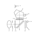
図2は本発明の実施の形態における光学系を示す図である。撮影レンズ1を通過した光束は、クイックリターンミラー2によって折り曲げられ拡散スクリーン3上にいったん結像する。その光束は更に、コンデンサレンズ4、ペンタプリズム5、接眼レンズ6を通って撮影者の眼に到達する。撮影時には、クイックリターンミラー2が跳ね上げられると同時に絞り7が設定値まで絞り込まれ、シャッター8が設定秒時だけ開きフィルム9への露光が行われる。また、シャッター8の全開に同期して閃光発光部10が設定された発光時間で発光する。フィルタ挿入部11は、撮影に先立ち閃光発光部10によって設定された閃光発光時間に対応した最適なフィルタを選択して撮影光路中に挿入する。撮影が終了すると、記録部14によって閃光発光時間がフィルム9に磁気記録される。
【0013】
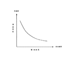
図3は、SBの発光時間とSB光の色温度との関係を示した図である。図に示したように、発光時間が短くなるほどSB光の色温度は高くなる。
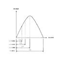
図4は、SBの発光時間と発光強度との関係を示した図である。図に示したように、最初発光強度は時間と共に大きくなり、ピークを過ぎると今度は小さくなり最後に消える。フル発光の場合には、このように不図示のコンデンサに充電した電荷を放電し終わるまで発光させるが、1/2発光、1/4発光、1/8発光の場合には、それぞれ発光を途中で中断させることによりその発光量を制御する。中断させる時間は、SBの個体ごとに、また同個体でも発光直前のコンデンサの充電電圧によって異なる。それぞれの発光量での発光時間は、SBの個体差及び充電電圧をパラメータとしてメモリに記憶しておいても良いし、別にモニター素子を設けてモニターしながら発光量が所定値になったらストップさせても良い。
【0014】
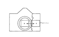
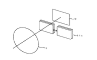
図5は、フィルタ挿入部11がカメラ内で動作する一例を説明した図である。図のように、一眼レフカメラのマウント後方に、例えばラック、ピニオン機構によってスライド可能なフィルタ挿入機構11aを設ける。フィルタは、異なる複数の色温度変換が可能なように複数枚が光軸方向に重なってAの位置に格納されている。そして、使用時は色温度変換値に応じて最適なフィルタを選択し、Bの位置にスライドするようにしておく。複数のフィルタのそれぞれがB位置にスライドしたときに、各々の検出スイッチがオンすることによって各フィルタの挿入が検出される。これによって、いかなるフィルタが選択され挿入されたのかを検出することができる。
【0015】
図6は、フィルタ挿入機構11aが、撮影レンズ1とフィルム9の間に挿入される所を説明した図である。
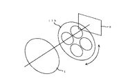
図7は、回転式のフィルタ挿入機構11bの説明図である。図のように、複数の異なる色温度変換値を持つフィルタを円板内に設けておき、使用時は色温度変換値に応じて最適なフィルタを円板の回転によって選択して光軸上に挿入する。円板の回転位置はエンコーダによって検出される。これによって、いかなるフィルタが選択され挿入されたのかを検出することができる。フィルタ挿入機構11bを設ける場所は、図5のようにマウント後方でも良いし、撮影レンズ1の鏡筒内でも良い。
【0016】
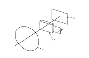
図8は、液晶式のフィルタ挿入機構11cの説明図である。図9に示したように、液晶にかける電圧値に応じて液晶濃度が変化し、色温度変換値が連続的に変わるようになっている。通常、SBの色温度はデーライトフィルムの標準色温度である5500°Kが標準であるが、発光時間が短くなるとそれよりも高くなる。従って、液晶の色は色温度を下げる方向であるアンバー系に着色しておき、色温度変換値に応じて濃度を制御すれば良い。また更に、ブルー系の液晶とアンバー系の液晶とを重ねる構成にしておけば、無色の状態から色温度を高い方にも低い方にも補正可能となる。
【0017】
図10は、記録部14が発光時間情報を記録する部分を示した図である。フィルム9において、9aは映像が光学的に記録されている部分、9bは情報が磁気記録されている部分である。発光時間情報は、記録部14に備えられた磁気ヘッドにより9b部分にデジタル信号で磁気記録される。また更に、フィルタ挿入部11で色温度が変換されたか否かの情報も記録しておくと、後の現像処理時に2重に色温度の補正がなされてしまうことを防止することもできる。
【0018】
図11は、本発明の実施の形態におけるカメラの動作を示したフローチャート図である。不図示のカメラのレリーズスイッチが半押しされることによりカメラの電源が入り本フローチャートが実行される。まず、ステップS101により設定部12に設定された発光モードを読みとる。この場合、発光モードにはフル発光、1/2発光、1/4発光、1/8発光の4種類がある。次にステップS102でフル発光モードであるかどうかを判定し、そうであればステップS103により発光時間を示す変数tに、図4に示した時間値t0を代入する。フル発光でない場合にはステップS104において1/2発光であるかを判定し、そうであればステップS105においてt=t1を代入する。そうでない場合にはステップS106において1/4発光であるかを判定し、そうであればステップS107においてt=t2を代入する。1/4発光でもない場合には1/8発光であるので、ステップS108においてt=t3を代入する。次に、ステップS109において設定された発光モードに応じた最適なフィルタを選択し、フィルタ挿入部11によって撮影光学系中に挿入する。ステップS110ではレリーズスイッチが全押しされたかどうかを判定し、全押しの場合にはステップS111によりフィルムへの露光制御を行い、次いでステップS112により記録部14によるフィルムへの磁気記録を行う。記録する情報は、SBの発光時間及び挿入されたフィルタ情報である。ステップS113では半押し起動時にスタートした半押しタイマが所定時間経過したかを判定し、まだ所定時間経過していない場合にはステップS101へ戻って処理を繰り返し、タイマ切れである場合にはプログラムを終了する。
【0019】
図12は、現像処理システムの構成を表したブロック図である。読みとり部15は、撮影されたフィルムに磁気記録されたSBの発光時間情報と挿入されたフィルタ情報を読みとる。補正値算出部16は、図3のようなSBの発光時間から求められる色温度情報と挿入された色温度変換フィルタ情報とから、プリント焼き付け時に補正すべき色温度変換値を算出する。露光部17は、算出された補正値に基づいて色温度の変換処理を施してプリント焼き付けを行う。
【0020】
【発明の効果】
以上詳しく説明したように本発明によれば、閃光装置の発光時間に応じてカラーバランスを補正する補正部を備えることにより、発光時間の違いによる閃光発光の色温度の違いを良好に補正することが可能となる。また、閃光装置の発光時間を記録可能なカメラで撮影された記録媒体のカラーバランスを良好に補正可能となる。
【図面の簡単な説明】
【図1】本発明のカメラの構成を示したブロック図である。
【図2】実施例の光学系を示した図である。
【図3】SBの発光時間と色温度との関係を示した図である。
【図4】SBの発光時間と発光強度との関係を示した図である。
【図5】実施例のフィルタ挿入部の動作をわかりやすく示した図である。
【図6】実施例のフィルタ挿入部を示した図である。
【図7】実施例のフィルタ挿入部を示した図である。
【図8】実施例のフィルタ挿入部を示した図である。
【図9】液晶の電圧を濃度との関係を示した図である。
【図10】フィルムへの記録部分を示した図である。
【図11】実施例の動作を示したフローチャート図である。
【図12】本発明の現像システムの構成を示したブロック図である。
【図13】従来技術を示した図である。
【図14】従来技術を示した図である。
【符号の説明】
1 撮影レンズ
2 クイックリターンミラー
3 拡散スクリーン
4 コンデンサレンズ
5 ペンタプリズム
6 接眼レンズ
7 絞り
8 シャッター
9 フィルム
10 閃光発光部
11 フィルタ挿入部
12 設定部
13 発光時間形成部
14 記録部
15 読みとり部
16 補正値算出部
17 露光部
101 調光ストロボ
102 積分回路
103 ホワイトバランス補正部
201 プリ発光部
202 色温度検出部
203 反射光量検出部
204 本発光量算出部
205 色温度変換部
206 本発光部
4[0001]
TECHNICAL FIELD OF THE INVENTION
The present invention relates to a camera using a flash light emitter or a developing system for developing a film photographed by the camera.
[0002]
[Prior art]
Conventionally, as a device for correcting a change in color temperature due to a difference in light emission time of a flash light emitter (hereinafter referred to as SB), there are devices as shown in Japanese Patent No. 2668984 and Japanese Patent Laid-Open No. 7-123423. . The former apparatus relates to white balance adjustment of an electronic camera, and includes a light control strobe 101, an integration circuit 102, and a white balance correction unit 103 as shown in FIG. The operation is that the integration circuit 102 obtains a voltage value proportional to the real time that the light control strobe 101 emits light during photographing, and the white balance correction unit 103 corrects the white balance of the photographed image according to the output. is there.
[0003]
The latter device relates to a strobe device that controls the color temperature of the strobe light. As shown in FIG. 14, the configuration includes a
[0004]
Here, the white balance and the color balance will be briefly described. White balance is a technology that adjusts the color balance so that a white subject appears white in an electronic image (mainly electrically). “In detail, when a white object illuminated by a light source of a certain color temperature is imaged, The camera encoder output for this must be in the state of subcarrier zero (electrically achromatic), which means adjusting the gain of each channel so that the subcarrier is zero for various color temperature light sources. The imaging means is limited to an electronic image.
[0005]
On the other hand, color balance literally refers to the overall technology for adjusting the color balance of the imaging means. “In detail, in color reproduction such as color photography, color printing, etc. The imaging means is not limited to an electronic image, saying that the color balance is good when the achromatic color is reproduced almost faithfully.
[0006]
[Problems to be solved by the invention]
However, in the apparatus shown in FIG. 13, the white balance correction unit 103 corrects the white balance after the light control strobe 101 has finished emitting light. There is a disadvantage that can not be. Further, the apparatus shown in FIG. 14 of HYPERLINK “IMG000016” has a drawback that it requires a complicated mechanism such as SB capable of pre-emission and color temperature detection means.
[0007]
Accordingly, the present invention provides a camera having a color balance correction function that does not require a complicated mechanism and can be applied to any camera, and a developing system for developing a film photographed by the camera. With the goal.
[0008]
[Means for Solving the Problems]
The above object is achieved by the following means. A light emission time forming unit that forms a signal according to a flash light emission time with a set issuance amount ; and a color temperature of the flash light emission that changes according to the light emission time based on output information of the light emission time formation unit In order to match the color temperature of the recording medium, by selectively inserting and removing a color balance correction filter in the photographic optical path and behind the photographic lens, the photographic light captures the color balance of the photographic light. A correction unit that corrects the light before entering the sensor; detection means for detecting that the filter has been inserted / removed; timer means for starting a predetermined time by pressing the release switch halfway; Determining means for determining whether or not the release switch has been operated after the insertion; the determining means determines that the release switch has been fully pressed; If it is determined that the release switch is not fully depressed, it is determined whether or not the predetermined time by the timer means has passed without performing the exposure control. Exposure control means for waiting for an output from the light emission time forming unit when the predetermined time has not elapsed, and ending a series of processing when the predetermined time has elapsed.
[0009]
According to a second aspect of the present invention, a light emission time forming unit that forms a signal according to a flash light emission time with a set issuance amount ; and a color balance of the photographing light according to an output of the light emission time forming unit is set in the photographing light path. A correction unit that includes a liquid crystal filter for color balance correction at the rear of the photographing lens, changes the liquid crystal density of the liquid crystal filter, and continuously changes the color temperature conversion value; Determining means for determining whether or not the release switch has been operated after the liquid crystal density has been changed; timer means for starting a predetermined time by pressing the release switch halfway; and determining the release by the determining means. When it is determined that the switch is fully pressed, exposure control is performed, but it is determined that the release switch is not fully pressed. If the predetermined time by the timer means is further determined without performing the exposure control, if the predetermined time has not elapsed, waiting for the output from the light emission time forming unit, Exposure control means for ending a series of processing when the predetermined time has elapsed.
[0011]
DETAILED DESCRIPTION OF THE INVENTION
Embodiments of the present invention will be described below with reference to the drawings. FIG. 1 is a block diagram showing the configuration of a camera according to an embodiment of the present invention. The flash
[0012]
FIG. 2 is a diagram showing an optical system according to the embodiment of the present invention. The light beam that has passed through the
[0013]
FIG. 3 is a diagram showing the relationship between the SB emission time and the color temperature of the SB light. As shown in the figure, the color temperature of the SB light increases as the light emission time decreases.
FIG. 4 is a diagram showing the relationship between the light emission time and the light emission intensity of SB. As shown in the figure, the first emission intensity increases with time, and after passing the peak, it decreases this time and finally disappears. In the case of full light emission, light is emitted until the electric charge charged in the capacitor (not shown) is completely discharged, but in the case of 1/2 light emission, 1/4 light emission, and 1/8 light emission, the light emission is halfway. The amount of light emission is controlled by interrupting at. The interruption time differs for each SB individual and also for the same individual depending on the charging voltage of the capacitor immediately before light emission. The light emission time for each light emission amount may be stored in the memory with individual differences of SB and charging voltage as parameters, or stopped when the light emission amount reaches a predetermined value while monitoring by providing a separate monitor element. May be.
[0014]
FIG. 5 is a diagram illustrating an example in which the
[0015]
FIG. 6 is a diagram illustrating a place where the filter insertion mechanism 11 a is inserted between the photographing
FIG. 7 is an explanatory diagram of the rotary filter insertion mechanism 11b. As shown in the figure, a filter with a plurality of different color temperature conversion values is provided in the disc, and when used, the optimum filter is selected by rotating the disc on the optical axis according to the color temperature conversion value. insert. The rotational position of the disc is detected by an encoder. This makes it possible to detect what filter has been selected and inserted. The place where the filter insertion mechanism 11b is provided may be behind the mount as shown in FIG.
[0016]
FIG. 8 is an explanatory diagram of a liquid crystal type filter insertion mechanism 11c. As shown in FIG. 9, the liquid crystal density changes according to the voltage value applied to the liquid crystal, and the color temperature conversion value changes continuously. Usually, the standard color temperature of SB is 5500 ° K which is the standard color temperature of the daylight film, but becomes higher as the light emission time becomes shorter. Therefore, the color of the liquid crystal may be colored in an amber system in which the color temperature is lowered, and the density may be controlled according to the color temperature conversion value. Furthermore, if the blue liquid crystal and the amber liquid crystal are stacked, the color temperature can be corrected from a colorless state to a higher or lower color temperature.
[0017]
FIG. 10 is a diagram showing a part where the recording unit 14 records the light emission time information. In the
[0018]
FIG. 11 is a flowchart showing the operation of the camera according to the embodiment of the present invention. When the release switch of a camera (not shown) is pressed halfway, the camera is turned on and this flowchart is executed. First, the light emission mode set in the setting unit 12 in step S101 is read. In this case, there are four types of emission modes: full emission, 1/2 emission, 1/4 emission, and 1/8 emission. Next, in step S102, it is determined whether or not it is the full light emission mode. If so, the time value t0 shown in FIG. 4 is substituted into the variable t indicating the light emission time in step S103. If it is not full light emission, it is determined in step S104 whether it is half light emission, and if so, t = t1 is substituted in step S105. If not, it is determined in step S106 whether the light emission is 1/4, and if so, t = t2 is substituted in step S107. If it is not 1/4 light emission, it is 1/8 light emission, so t = t3 is substituted in step S108. Next, an optimum filter corresponding to the light emission mode set in step S109 is selected and inserted into the photographing optical system by the
[0019]
FIG. 12 is a block diagram showing the configuration of the development processing system. The reading unit 15 reads the SB light emission time information magnetically recorded on the photographed film and the inserted filter information. The correction value calculation unit 16 calculates a color temperature conversion value to be corrected at the time of print printing from the color temperature information obtained from the SB emission time as shown in FIG. 3 and the inserted color temperature conversion filter information. The
[0020]
【The invention's effect】
As described above in detail, according to the present invention, by providing a correction unit that corrects the color balance according to the light emission time of the flash device, it is possible to satisfactorily correct the difference in the color temperature of the flash light emission due to the difference in the light emission time. Is possible. In addition, it is possible to satisfactorily correct the color balance of a recording medium shot with a camera capable of recording the light emission time of the flash device.
[Brief description of the drawings]
FIG. 1 is a block diagram showing a configuration of a camera of the present invention.
FIG. 2 is a diagram illustrating an optical system of an example.
FIG. 3 is a diagram illustrating a relationship between a light emission time of SB and a color temperature.
FIG. 4 is a diagram showing a relationship between SB emission time and emission intensity.
FIG. 5 is a diagram showing the operation of the filter insertion unit of the embodiment in an easy-to-understand manner.
FIG. 6 is a diagram illustrating a filter insertion portion of the embodiment.
FIG. 7 is a diagram illustrating a filter insertion portion of the embodiment.
FIG. 8 is a diagram illustrating a filter insertion portion of the embodiment.
FIG. 9 is a graph showing the relationship between the voltage of the liquid crystal and the concentration.
FIG. 10 is a diagram showing a recording portion on a film.
FIG. 11 is a flowchart showing the operation of the embodiment.
FIG. 12 is a block diagram showing a configuration of a developing system of the present invention.
FIG. 13 is a diagram showing a conventional technique.
FIG. 14 is a diagram showing a conventional technique.
[Explanation of symbols]
DESCRIPTION OF
Four
Claims (2)
前記フィルターが挿脱されたことを検出する検出手段と;
レリーズスイッチが半押し操作されることによって所定時間の計時を開始するタイマ手段と;
前記フィルターが挿入された後に、レリーズスイッチが操作されたか否かを判断する判断手段と;
該判断手段によって前記レリーズスイッチが全押し操作されたと判断された場合、露光制御を行なうが、前記レリーズスイッチが全押し操作されていないと判断された場合、前記露出制御を行なうことなく、さらに前記タイマ手段による前記所定時間が経過したか否かを判断し、前記所定時間が経過していない場合、前記発光時間形成部からの出力を待機し、前記所定時間が経過した場合、一連の処理を終了させる露光制御手段と;を備えることを特徴とするカメラ。A light emission time forming unit for forming a signal corresponding to a flash light emission time with a set issuance amount ; and based on output information of the light emission time formation unit, the color temperature of the flash light emission that changes according to the light emission time In order to match the temperature, the color balance correction filter is selectively inserted and removed in the imaging optical path and behind the imaging lens, so that the color balance of the imaging light is made before the imaging light enters the imaging unit. A correction unit to be corrected;
Detection means for detecting that the filter has been inserted and removed;
Timer means for starting a predetermined time by pressing the release switch halfway;
Determining means for determining whether or not a release switch has been operated after the filter has been inserted;
When it is determined by the determining means that the release switch has been fully pressed, exposure control is performed. However, when it is determined that the release switch has not been fully pressed, the exposure control is not performed and the exposure control is further performed. It is determined whether or not the predetermined time has elapsed by the timer means. When the predetermined time has not elapsed, the output from the light emission time forming unit is waited. When the predetermined time has elapsed, a series of processing is performed. An exposure control means for terminating the camera.
前記液晶フィルターの液晶濃度が変更された後に、レリーズスイッチが操作されたか否かを判断する判断手段と;
レリーズスイッチが半押し操作されることによって所定時間の計時を開始するタイマ手段と;
該判断手段によって前記レリーズスイッチが全押し操作されたと判断された場合、露光制御を行なうが、前記レリーズスイッチが全押し操作されていないと判断された場合、前記露出制御を行なうことなく、さらに前記タイマ手段による前記所定時間が経過したか否かを判断し、前記所定時間が経過していない場合、前記発光時間形成部からの出力を待機し、前記所定時間が経過した場合、一連の処理を終了させる露光制御手段と;を備えることを特徴とするカメラ。A light emission time forming unit for forming a signal corresponding to the flash light emission time with a set issuance amount ; and a color balance of the photographing light according to the output of the light emission time forming unit in the photographing optical path and behind the photographing lens A correction unit that includes a liquid crystal filter for color balance correction, changes the liquid crystal density of the liquid crystal filter, and continuously changes the color temperature conversion value;
Determining means for determining whether or not a release switch has been operated after the liquid crystal density of the liquid crystal filter has been changed;
Timer means for starting a predetermined time by pressing the release switch halfway;
When it is determined by the determining means that the release switch has been fully pressed, exposure control is performed. However, when it is determined that the release switch has not been fully pressed, the exposure control is not performed and the exposure control is further performed. It is determined whether or not the predetermined time has elapsed by the timer means. When the predetermined time has not elapsed, the output from the light emission time forming unit is waited. When the predetermined time has elapsed, a series of processing is performed. An exposure control means for terminating the camera.
Priority Applications (1)
| Application Number | Priority Date | Filing Date | Title |
|---|---|---|---|
| JP33854498A JP4423686B2 (en) | 1998-11-30 | 1998-11-30 | Camera and development system |
Applications Claiming Priority (1)
| Application Number | Priority Date | Filing Date | Title |
|---|---|---|---|
| JP33854498A JP4423686B2 (en) | 1998-11-30 | 1998-11-30 | Camera and development system |
Publications (3)
| Publication Number | Publication Date |
|---|---|
| JP2000162678A JP2000162678A (en) | 2000-06-16 |
| JP2000162678A5 JP2000162678A5 (en) | 2005-11-17 |
| JP4423686B2 true JP4423686B2 (en) | 2010-03-03 |
Family
ID=18319173
Family Applications (1)
| Application Number | Title | Priority Date | Filing Date |
|---|---|---|---|
| JP33854498A Expired - Lifetime JP4423686B2 (en) | 1998-11-30 | 1998-11-30 | Camera and development system |
Country Status (1)
| Country | Link |
|---|---|
| JP (1) | JP4423686B2 (en) |
Families Citing this family (1)
| Publication number | Priority date | Publication date | Assignee | Title |
|---|---|---|---|---|
| WO2006090837A1 (en) * | 2005-02-25 | 2006-08-31 | Nikon Corporation | Color temperature converting element, color temperature converting device, and illuminator |
-
1998
- 1998-11-30 JP JP33854498A patent/JP4423686B2/en not_active Expired - Lifetime
Also Published As
| Publication number | Publication date |
|---|---|
| JP2000162678A (en) | 2000-06-16 |
Similar Documents
| Publication | Publication Date | Title |
|---|---|---|
| JP4423686B2 (en) | Camera and development system | |
| JP2535797B2 (en) | camera | |
| JPH0869091A (en) | Film with lens | |
| JPH1195293A (en) | Image pickup device | |
| JPH10142685A (en) | Silver salt photographic and electronic image pickup camera | |
| JP2695325B2 (en) | How to make a print photo | |
| JP3617057B2 (en) | Electronic still camera | |
| JP2801985B2 (en) | How to make a print photo | |
| JP2899839B2 (en) | Infrared film camera | |
| JP2002116370A (en) | Image pickup device, focus control device, electronic camera and focusing method | |
| JPH07191381A (en) | Camera capable of imprinting data | |
| JPH0572649A (en) | Method for forming photographic print | |
| JPH1048742A (en) | Camera | |
| JP2002122928A (en) | Camera | |
| JPH0789192B2 (en) | camera | |
| JP2000089283A (en) | Camera provided with shake correction function | |
| JPS62146090A (en) | Electronic still camera | |
| JPH06141230A (en) | Electronic still camera | |
| JPH10246914A (en) | Camera capable of magnetic recording | |
| JPH08328123A (en) | Magnetically recordable camera | |
| JPH08304908A (en) | Camera provided with information recording function | |
| JP2002118786A (en) | Imaging unit, photometer, electronic camera, and photometry method | |
| JPH1048740A (en) | Camera | |
| JPH08262528A (en) | Automatic control camera | |
| JPH0865615A (en) | Photographing device |
Legal Events
| Date | Code | Title | Description |
|---|---|---|---|
| A521 | Request for written amendment filed |
Free format text: JAPANESE INTERMEDIATE CODE: A523 Effective date: 20050922 |
|
| A621 | Written request for application examination |
Free format text: JAPANESE INTERMEDIATE CODE: A621 Effective date: 20050922 |
|
| A131 | Notification of reasons for refusal |
Free format text: JAPANESE INTERMEDIATE CODE: A131 Effective date: 20081007 |
|
| A521 | Request for written amendment filed |
Free format text: JAPANESE INTERMEDIATE CODE: A523 Effective date: 20081208 |
|
| A131 | Notification of reasons for refusal |
Free format text: JAPANESE INTERMEDIATE CODE: A131 Effective date: 20090217 |
|
| A521 | Request for written amendment filed |
Free format text: JAPANESE INTERMEDIATE CODE: A523 Effective date: 20090420 |
|
| A131 | Notification of reasons for refusal |
Free format text: JAPANESE INTERMEDIATE CODE: A131 Effective date: 20090707 |
|
| A521 | Request for written amendment filed |
Free format text: JAPANESE INTERMEDIATE CODE: A523 Effective date: 20090907 |
|
| TRDD | Decision of grant or rejection written | ||
| A01 | Written decision to grant a patent or to grant a registration (utility model) |
Free format text: JAPANESE INTERMEDIATE CODE: A01 Effective date: 20091117 |
|
| A01 | Written decision to grant a patent or to grant a registration (utility model) |
Free format text: JAPANESE INTERMEDIATE CODE: A01 |
|
| A61 | First payment of annual fees (during grant procedure) |
Free format text: JAPANESE INTERMEDIATE CODE: A61 Effective date: 20091130 |
|
| R150 | Certificate of patent or registration of utility model |
Free format text: JAPANESE INTERMEDIATE CODE: R150 |
|
| FPAY | Renewal fee payment (event date is renewal date of database) |
Free format text: PAYMENT UNTIL: 20121218 Year of fee payment: 3 |
|
| FPAY | Renewal fee payment (event date is renewal date of database) |
Free format text: PAYMENT UNTIL: 20121218 Year of fee payment: 3 |
|
| FPAY | Renewal fee payment (event date is renewal date of database) |
Free format text: PAYMENT UNTIL: 20151218 Year of fee payment: 6 |
|
| FPAY | Renewal fee payment (event date is renewal date of database) |
Free format text: PAYMENT UNTIL: 20151218 Year of fee payment: 6 |
|
| S531 | Written request for registration of change of domicile |
Free format text: JAPANESE INTERMEDIATE CODE: R313531 |
|
| R350 | Written notification of registration of transfer |
Free format text: JAPANESE INTERMEDIATE CODE: R350 |
|
| R250 | Receipt of annual fees |
Free format text: JAPANESE INTERMEDIATE CODE: R250 |
|
| R250 | Receipt of annual fees |
Free format text: JAPANESE INTERMEDIATE CODE: R250 |
|
| R250 | Receipt of annual fees |
Free format text: JAPANESE INTERMEDIATE CODE: R250 |
|
| EXPY | Cancellation because of completion of term |

