JP4423272B2 - Stereolithography equipment - Google Patents
Stereolithography equipment Download PDFInfo
- Publication number
- JP4423272B2 JP4423272B2 JP2006162180A JP2006162180A JP4423272B2 JP 4423272 B2 JP4423272 B2 JP 4423272B2 JP 2006162180 A JP2006162180 A JP 2006162180A JP 2006162180 A JP2006162180 A JP 2006162180A JP 4423272 B2 JP4423272 B2 JP 4423272B2
- Authority
- JP
- Japan
- Prior art keywords
- film
- photocurable resin
- sealing material
- light
- cured
- Prior art date
- Legal status (The legal status is an assumption and is not a legal conclusion. Google has not performed a legal analysis and makes no representation as to the accuracy of the status listed.)
- Expired - Fee Related
Links
Images


Description
この発明は、光造形装置に関し、特に、立体形状を連続的に形成できる光造形装置に関する。 The present invention relates to an optical modeling apparatus, and more particularly to an optical modeling apparatus capable of continuously forming a three-dimensional shape.
従来の3次元光造形装置がたとえば、特開2002−370286号公報(特許文献1)や特開2003−39564号公報(特許文献2)に記載されている。 Conventional three-dimensional stereolithography apparatuses are described in, for example, Japanese Patent Application Laid-Open No. 2002-370286 (Patent Document 1) and Japanese Patent Application Laid-Open No. 2003-39564 (Patent Document 2).
特許文献1によれば、ガラス面の上に透明な弾性分離層を設け、その上に光硬化性樹脂を載置し、ガラス面の下部から光を照射して光硬化性樹脂を硬化させて3次元造形を行う装置が開示されている。この装置においては、弾性分離層として、ラテックスまたはシリコンゴムのような高弾性材料の膜を使用することにより、膜はガラス面に付着せず、ガス媒体または液体媒体を膜とガラス面との間に流入させて膜と造形部分とを分離させている。
According to
また、特許文献2によれば、特許文献1と同様の、透明板の上に弾性体が設けられ、弾性体の上に光硬化性樹脂が保持される光造形装置が開示され、弾性体は、透明板から離れるよりも、凝固された材料が弾性層からより容易に離れるように構成されている。
従来の3次元光造形装置は上記のように構成されていた。光の照射により硬化した部分を膜から離すために、高弾性材料の膜のような特殊な処理が行われた膜や、膜とガラス面との間に媒体を流入させる装置が必要となり、装置が複雑で高価になるという問題があった。 A conventional three-dimensional stereolithography apparatus is configured as described above. In order to separate the part hardened by light irradiation from the film, a specially treated film such as a film of highly elastic material or a device that allows the medium to flow between the film and the glass surface is required. There was a problem that was complicated and expensive.
この発明は、上記のような問題点に鑑みてなされたもので、構造が簡単でコストの安価な光造形装置を提供することを目的とする。 The present invention has been made in view of the above-described problems, and an object thereof is to provide an optical modeling apparatus that has a simple structure and is inexpensive.
この発明にかかる、光造形装置は、透光性を有する板と、透光性を有する板の上に設けられ、所定の方向に移動可能なフィルムと、フィルム上に密着して設けられ、フィルム上の所定の範囲を囲うシール材と、シール材の内部に光によって硬化する光硬化性樹脂を供給する光硬化性樹脂供給装置と、光硬化性樹脂に対して、光を照射する光照射手段と、光照射手段によって硬化された光硬化性樹脂の硬化された部分を板に対して相対的に移動させる移動装置とを含む。 An optical modeling apparatus according to the present invention is provided on a translucent plate, a translucent plate, a film movable in a predetermined direction, and provided in close contact with the film. A sealing material that surrounds the predetermined range above, a photocurable resin supply device that supplies a photocurable resin that is cured by light inside the sealing material, and a light irradiation means that irradiates the photocurable resin with light And a moving device that moves the cured portion of the photocurable resin cured by the light irradiation means relative to the plate.
この発明においては、透光性を有する板の上には、所定の方向に移動可能なフィルムを設け、フィルム上に密着してフィルム上の所定の範囲を囲うシール材とを設けたため、光硬化性樹脂の所定の部分を硬化した後、フィルムを横方向に移動するだけで、フィルムと造形部とを分離できる。 In the present invention, a film that can move in a predetermined direction is provided on a light-transmitting plate, and a sealing material that is in close contact with the film and surrounds a predetermined range on the film is provided. After curing a predetermined portion of the conductive resin, the film and the modeled portion can be separated simply by moving the film laterally.
その結果、構造が簡単でコストの安価な光造形装置を提供できる。 As a result, an optical modeling apparatus having a simple structure and a low cost can be provided.
また、シール材はVリングで構成されてもよい。さらに、フィルムを所定の方向に移動させるフィルム巻取り機構を含み、光硬化性樹脂の一部が硬化した後に、フィルム巻き取り機構でフィルムを移動させる構造にしてもよい。 Further, the sealing material may be composed of a V ring. Furthermore, a film winding mechanism for moving the film in a predetermined direction may be included, and the film may be moved by the film winding mechanism after a part of the photocurable resin is cured.
さらに好ましくは、フィルムにはシリコンが塗布されている。 More preferably, the film is coated with silicon.
以下、この発明の一実施の形態について、図面を参照して説明する。図1は、この発明の一実施の形態に係る、光造形装置を示す図である。図1(A)は側面図であり、図1(B)は、図1(A)において、矢印B-Bで示す部分の平面図である。 Hereinafter, an embodiment of the present invention will be described with reference to the drawings. FIG. 1 is a diagram showing an optical modeling apparatus according to an embodiment of the present invention. 1A is a side view, and FIG. 1B is a plan view of a portion indicated by an arrow BB in FIG. 1A.
図1(A)および(B)を参照して、光造形装置10は、ガラス板11と、ガラス板11の上にa方向(図1(B)参照)に移動可能に設けられたフィルム12と、フィルム12の上に載置するされた、円筒形状のシール材15と、後に説明する硬化した樹脂21をテーブル17を用いて引き上げるテーブル昇降機構16とを含む。フィルム12は、駆動部を有する巻き取りローラ14と、従動ローラ13とによって保持され、巻き取りローラ14によって巻き取られる。ここで、テーブル昇降機構16は移動装置として機能する。
1A and 1B, an
ガラス板11、巻き取りローラ14、従動ローラ13およびシール材15は、固定枠23で固定されている。固定枠23は立上り部を有し、この立上り部の一部にヒンジ25が設けられ、このヒンジ25の先端にシール材15を保持するためのシール材保持部24が設けられている。ヒンジ25は図中矢印cで示すように回動可能であり、フィルム12をガラス板11の上に通したあと、このヒンジ25を回動させてフィルム12上にシール材15を載置する。
The
シール材15の内部には、図示のない光硬化性樹脂供給装置から、光硬化性樹脂が適時供給されている。ガラス板11の下部には、プロジェクタ(光照射手段)30が設けられ、プロジェクタ30から光硬化性樹脂を硬化するための光がガラス板11の所定の部分(図1(A)において22で示す部分)に光路31を経て照射され、この部分が硬化される。
A photocurable resin is supplied to the inside of the sealing
光硬化性樹脂20の硬化された部分22は、テーブル昇降機構16の下端に設けられたテーブル17に接続され、テーブル17は、テーブル昇降機構16の図示のない駆動部によって図中bで示す方向に持ち上げられる。なお、フィルム12は、弾性を有さないPET(ポリエチレンテレフタラート)フィルムが好ましい。また、その表面はシリコンでコートされているのが好ましい。
The cured
このような構成とすることで、材料となる光硬化性樹脂の供給量は常に積層硬化させるギャップ以上の液面高さがあればよいので、材料の供給をきわめて少なくできる。具体的には、図1に示した、硬化された部分22の高さ以上まであればよい。この液面の制御は、図示のないセンサで行われる。
By adopting such a configuration, the supply amount of the photo-curing resin as a material only needs to have a liquid level higher than the gap to be laminated and cured at all times, so that the supply of the material can be extremely reduced. Specifically, it may be up to the height of the cured
その硬化された部分の高さ(ギャップ)の寸法としては、0.01〜0.5mmに設定可能である。 The dimension of the height (gap) of the cured portion can be set to 0.01 to 0.5 mm.
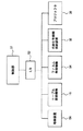
図2は、光造形装置10における制御に関する主要構成要素を示すブロック図である。図2を参照して、光造形装置10は、光造形装置10全体を制御するための、CPUを含む、制御部51と、制御部51に対して、入出力インターフェイス(I/O)52を介して接続される、テーブル昇降機構16と、フィルム巻取り機構54と、光硬化性樹脂供給装置55と、プロジェクタ30と、プログラムやデータを保持する格納装置56とを含む。
FIG. 2 is a block diagram illustrating main components related to control in the
フィルム巻き取り機構54は上記したフィルム12、駆動部を有する巻き取りローラ14および従動ローラ13を含む。
The film take-
光造形装置10によって、光硬化性樹脂20を用いて造形されるときは、まず、ガラス板11の上にフィルム12を通過させ、フィルム12のほぼ中央にシール材15を載置し、シール材15の内部に光硬化性樹脂20を図示のない、光硬化性樹脂供給装置55を用いて供給する。この状態で、プロジェクタ30から光を照射し、光硬化性樹脂20の下面の一部を所望の形状に硬化させる。具体的には、上記したように、光硬化性樹脂20のガラス面側の一部22を所定の厚さだけ硬化する。硬化後、テーブル昇降機構16で、硬化された光硬化性樹脂に接続されたテーブル17を、所定の高さまで引き上げる。所定の高さとしては、通常の成形寸法に対して、100倍程度である。通常の成形寸法が0.05mmであれば、5mmにするのがよい。この理由は、隙間を設けることによって樹脂が次に硬化させる部分に流れ込むことができるようにするためである。
When being modeled by the
このとき同時に、フィルム12を所定の長さだけ巻き取りローラ14で巻き取る。この動作によって、硬化された部分22のフィルム12からの剥離が容易になる。
At the same time, the
次に、テーブル17とフィルム12の上面とのギャップを所定の成形寸法とするために、テーブル17を降下させる。
Next, the table 17 is lowered so that the gap between the table 17 and the upper surface of the
この状態で再びプロジェクタ30から光を照射して光硬化性樹脂を硬化させる。このプロセスを繰り返すことによって、3次元造形物を生成する。
In this state, light is again irradiated from the
なお、この所望の形状に形成するためのプログラムは、格納装置56に格納されており、そのプログラムに沿って、プロジェクタ30の露光位置や露光量、および、テーブル昇降機構16の昇降量が制御される。
The program for forming the desired shape is stored in the
次に、シール材15について説明する。ここで用いるシール材15としては、Vリングが好ましい。Vリングとは回転軸のシールに用いられるシール材であり、特に、フォーシェタ社のものが好ましい。図3に示すように、Vリング40は、軸受部分42をシールするために軸41に取り付けられ、その先端部40aは本体43の側面と摺動する状態で使用される。この先端部40aが図1におけるフィルム12に当接する。このようなシール材であれば、フィルム12の移動時においても、その摺動部における発熱等の問題も生じない。
Next, the sealing
次に、シール材15の変形例について説明する。図4は、シール材の変形例を示す図である。図4を参照して、この例では、シール材15は、光硬化性樹脂20を保持する本体部45を有し、本体部45には、その外周部には環状の溝45aとフィルム12に当接する先端部45bとが設けられている。溝45aには、溝45aを上下方向に付勢するバネ46が設けられ、この付勢力で先端部45bがフィルム12に当接される。このような構成であれば、光硬化性樹脂20は十分シールされる。
Next, a modified example of the sealing
なお、上記実施の形態においては、シール材として、先端部が外部に広がっている例について説明したが、これに限らず、内側に狭くなっていても良い。 In addition, in the said embodiment, although the example which the front-end | tip part has spread outside as a sealing material was demonstrated, it is not restricted to this, You may narrow inside.
また、上記実施の形態においては、フィルムに塗布する材料としてシリコンを例にあげたが、これに限らず、離型性を有するものであれば任意のものを採用してもよい。 Moreover, in the said embodiment, although silicon was mentioned as an example as a material applied to a film, not only this but arbitrary things may be employ | adopted if it has mold release property.
さらに、ガラス板の代わりに、光透過性を有する任意の板を使用してもよい。また、シール材の形状は、円形に限らず、矩形状であってもよいし、楕円形であってもよい。 Furthermore, you may use the arbitrary board | substrate which has a light transmittance instead of a glass plate. Further, the shape of the sealing material is not limited to a circular shape, and may be a rectangular shape or an elliptical shape.
また、上記実施の形態においては、光照射手段としてプロジェクタを例にあげて説明したが、これに限らず、光を照射できれば、任意の形式であってもよい。 In the above embodiment, the projector has been described as an example of the light irradiating means. However, the present invention is not limited to this, and any form may be used as long as light can be irradiated.
また、上記実施の形態においては、光硬化性樹脂の硬化後、テーブル昇降機構で、硬化された光硬化性樹脂に接続されたテーブルを、所定の高さとなる位置まで引き上げる例について説明したが、これに限らず、ガラス板の方を引き下げるようにしてもよい。 Further, in the above embodiment, an example in which the table connected to the cured photocurable resin is pulled up to a predetermined height by the table lifting mechanism after the photocurable resin is cured has been described. Not limited to this, the glass plate may be pulled down.
以上、図面を参照してこの発明の実施形態を説明したが、この発明は、図示した実施形態のものに限定されない。図示された実施形態に対して、この発明と同一の範囲内において、あるいは均等の範囲内において、種々の修正や変形を加えることが可能である。 As mentioned above, although embodiment of this invention was described with reference to drawings, this invention is not limited to the thing of embodiment shown in figure. Various modifications and variations can be made to the illustrated embodiment within the same range or equivalent range as the present invention.
光造形において、フィルム上で成形し、所定の部分が硬化すると、テーブル昇降機構を用いて成形部分を持ち上げると同時に、フィルムを移動するようにしたため、特殊なフィルムを用いることなく、光硬化性樹脂を必要最小限の量で成形できるとともに、構成を簡単にできるため、光造形装置として有利に使用される。 In stereolithography, when a predetermined part is molded on a film, the molded part is lifted using a table lifting mechanism, and the film is moved at the same time. Therefore, a photocurable resin is used without using a special film. Can be molded in the minimum amount necessary, and the configuration can be simplified, so that it is advantageously used as an optical modeling apparatus.
10 光造形装置、11 ガラス板、12 フィルム、13 従動ローラ、14 巻き取りローラ、15 シール材、16 テーブル昇降機構、17 テーブル、18 サポート、20 光硬化性樹脂、30 プロジェクタ。
DESCRIPTION OF
Claims (5)
前記透光性を有する板の上に設けられたフィルムと、
前記フィルムを前記板の上に通過移動させるための手段と、
前記フィルム上に設けられ、前記フィルム上の所定の範囲を囲うシール材と、
前記シール材の内部に光によって硬化する光硬化性樹脂を供給する光硬化性樹脂供給装置と、
前記光硬化性樹脂に対して、光を照射する光照射手段と、
を含む、光造形装置。 A translucent plate;
A film provided on the translucent plate;
Means for moving the film over the plate ;
A sealing material provided on the film and enclosing a predetermined area on the film;
A photocurable resin supply device for supplying a photocurable resin that is cured by light into the sealing material;
A light irradiation means for irradiating the photocurable resin with light;
An optical modeling apparatus including:
前記透光性を有する板の上に設けられたフィルムと、
前記フィルムを前記板の上に通過移動させるための手段と、
前記フィルム上に設けられ、前記フィルム上の所定の範囲を囲うシール材と、
前記シール材の内部に光によって硬化する光硬化性樹脂を供給する光硬化性樹脂供給装置と、
前記光硬化性樹脂に対して、光を照射する光照射手段と、
前記光照射手段によって硬化された光硬化性樹脂の硬化された部分を前記板に対して相対的に移動させる移動装置と、
を含む、光造形装置。 A translucent plate;
A full Irumu provided on the plate with the light-transmitting,
Means for moving the film over the plate ;
A sealing material provided on the film and enclosing a predetermined area on the film;
A photocurable resin supply device for supplying a photocurable resin that is cured by light into the sealing material;
A light irradiation means for irradiating the photocurable resin with light;
A moving device for moving the cured portion of the photocurable resin cured by the light irradiation means relative to the plate;
An optical modeling apparatus including:
Priority Applications (1)
| Application Number | Priority Date | Filing Date | Title |
|---|---|---|---|
| JP2006162180A JP4423272B2 (en) | 2006-06-12 | 2006-06-12 | Stereolithography equipment |
Applications Claiming Priority (1)
| Application Number | Priority Date | Filing Date | Title |
|---|---|---|---|
| JP2006162180A JP4423272B2 (en) | 2006-06-12 | 2006-06-12 | Stereolithography equipment |
Related Child Applications (1)
| Application Number | Title | Priority Date | Filing Date |
|---|---|---|---|
| JP2009262483A Division JP4813594B2 (en) | 2009-11-18 | 2009-11-18 | Stereolithography equipment |
Publications (3)
| Publication Number | Publication Date |
|---|---|
| JP2007331118A JP2007331118A (en) | 2007-12-27 |
| JP2007331118A5 JP2007331118A5 (en) | 2009-07-30 |
| JP4423272B2 true JP4423272B2 (en) | 2010-03-03 |
Family
ID=38931068
Family Applications (1)
| Application Number | Title | Priority Date | Filing Date |
|---|---|---|---|
| JP2006162180A Expired - Fee Related JP4423272B2 (en) | 2006-06-12 | 2006-06-12 | Stereolithography equipment |
Country Status (1)
| Country | Link |
|---|---|
| JP (1) | JP4423272B2 (en) |
Families Citing this family (2)
| Publication number | Priority date | Publication date | Assignee | Title |
|---|---|---|---|---|
| KR100887185B1 (en) * | 2007-09-28 | 2009-03-10 | 한국과학기술원 | Colorable rapid prototyping apparatus using face level lamination |
| JP2015027738A (en) * | 2013-07-30 | 2015-02-12 | ローランドディー.ジー.株式会社 | Three-dimensional contouring apparatus |
-
2006
- 2006-06-12 JP JP2006162180A patent/JP4423272B2/en not_active Expired - Fee Related
Also Published As
| Publication number | Publication date |
|---|---|
| JP2007331118A (en) | 2007-12-27 |
Similar Documents
| Publication | Publication Date | Title |
|---|---|---|
| JP4813594B2 (en) | Stereolithography equipment | |
| US20220016811A1 (en) | Apparatus and method for making an object | |
| US11787138B2 (en) | Methods and apparatuses for casting polymer products | |
| US10150280B2 (en) | Apparatus for fabrication of three dimensional objects | |
| EP3204217B1 (en) | Shifting a curing location during 3d printing | |
| TW201637824A (en) | Additive manufacturing device with release mechanism | |
| JP2008155477A (en) | Three-dimensional modeling apparatus | |
| JP2010240865A (en) | Optical shaping apparatus | |
| US20210331377A1 (en) | Apparatus and method for three-dimensional printing | |
| WO2017219942A1 (en) | Resin reservoir for photocuring for use in 3d printer and 3d printer | |
| CN110920056A (en) | Method for improving 3D printing surface flatness | |
| JP4423272B2 (en) | Stereolithography equipment | |
| US20190091930A1 (en) | Three-dimensional printing device and liquid tank thereof | |
| US11351723B2 (en) | Systems, devices, and methods for manufacturing three dimensional objects via oxygen permeation of a gas permeable membrane | |
| KR101776778B1 (en) | Three dimensional printer for tilting resin storage | |
| TWI655077B (en) | Three dimensional printing device | |
| JP2007331118A5 (en) | ||
| JP2007090619A (en) | Optical molding apparatus | |
| CN115230146A (en) | 3D printing method and 3D printing system | |
| JPH06305031A (en) | Apparatus for feeding photocurable resin | |
| TW201706114A (en) | Three-dimensional printing device of reducing the pulling force of the luminous surface forming | |
| JP2016162839A (en) | Imprint printing device |
Legal Events
| Date | Code | Title | Description |
|---|---|---|---|
| A521 | Request for written amendment filed |
Free format text: JAPANESE INTERMEDIATE CODE: A523 Effective date: 20090611 |
|
| A621 | Written request for application examination |
Free format text: JAPANESE INTERMEDIATE CODE: A621 Effective date: 20090611 |
|
| A871 | Explanation of circumstances concerning accelerated examination |
Free format text: JAPANESE INTERMEDIATE CODE: A871 Effective date: 20090622 |
|
| A975 | Report on accelerated examination |
Free format text: JAPANESE INTERMEDIATE CODE: A971005 Effective date: 20090702 |
|
| A131 | Notification of reasons for refusal |
Free format text: JAPANESE INTERMEDIATE CODE: A131 Effective date: 20090707 |
|
| A521 | Request for written amendment filed |
Free format text: JAPANESE INTERMEDIATE CODE: A523 Effective date: 20090904 |
|
| A131 | Notification of reasons for refusal |
Free format text: JAPANESE INTERMEDIATE CODE: A131 Effective date: 20091020 |
|
| A521 | Request for written amendment filed |
Free format text: JAPANESE INTERMEDIATE CODE: A523 Effective date: 20091030 |
|
| TRDD | Decision of grant or rejection written | ||
| A01 | Written decision to grant a patent or to grant a registration (utility model) |
Free format text: JAPANESE INTERMEDIATE CODE: A01 Effective date: 20091201 |
|
| A01 | Written decision to grant a patent or to grant a registration (utility model) |
Free format text: JAPANESE INTERMEDIATE CODE: A01 |
|
| A61 | First payment of annual fees (during grant procedure) |
Free format text: JAPANESE INTERMEDIATE CODE: A61 Effective date: 20091207 |
|
| FPAY | Renewal fee payment (event date is renewal date of database) |
Free format text: PAYMENT UNTIL: 20121211 Year of fee payment: 3 |
|
| R150 | Certificate of patent or registration of utility model |
Ref document number: 4423272 Country of ref document: JP Free format text: JAPANESE INTERMEDIATE CODE: R150 |
|
| FPAY | Renewal fee payment (event date is renewal date of database) |
Free format text: PAYMENT UNTIL: 20131211 Year of fee payment: 4 |
|
| R250 | Receipt of annual fees |
Free format text: JAPANESE INTERMEDIATE CODE: R250 |
|
| R250 | Receipt of annual fees |
Free format text: JAPANESE INTERMEDIATE CODE: R250 |
|
| R250 | Receipt of annual fees |
Free format text: JAPANESE INTERMEDIATE CODE: R250 |
|
| R250 | Receipt of annual fees |
Free format text: JAPANESE INTERMEDIATE CODE: R250 |
|
| R250 | Receipt of annual fees |
Free format text: JAPANESE INTERMEDIATE CODE: R250 |
|
| R250 | Receipt of annual fees |
Free format text: JAPANESE INTERMEDIATE CODE: R250 |
|
| R250 | Receipt of annual fees |
Free format text: JAPANESE INTERMEDIATE CODE: R250 |
|
| R250 | Receipt of annual fees |
Free format text: JAPANESE INTERMEDIATE CODE: R250 |
|
| R250 | Receipt of annual fees |
Free format text: JAPANESE INTERMEDIATE CODE: R250 |
|
| LAPS | Cancellation because of no payment of annual fees |