JP4420006B2 - Grommet - Google Patents
Grommet Download PDFInfo
- Publication number
- JP4420006B2 JP4420006B2 JP2006279943A JP2006279943A JP4420006B2 JP 4420006 B2 JP4420006 B2 JP 4420006B2 JP 2006279943 A JP2006279943 A JP 2006279943A JP 2006279943 A JP2006279943 A JP 2006279943A JP 4420006 B2 JP4420006 B2 JP 4420006B2
- Authority
- JP
- Japan
- Prior art keywords
- bent
- grommet
- thickness
- region
- vehicle body
- Prior art date
- Legal status (The legal status is an assumption and is not a legal conclusion. Google has not performed a legal analysis and makes no representation as to the accuracy of the status listed.)
- Expired - Fee Related
Links
Images


Classifications
-
- B—PERFORMING OPERATIONS; TRANSPORTING
- B60—VEHICLES IN GENERAL
- B60R—VEHICLES, VEHICLE FITTINGS, OR VEHICLE PARTS, NOT OTHERWISE PROVIDED FOR
- B60R16/00—Electric or fluid circuits specially adapted for vehicles and not otherwise provided for; Arrangement of elements of electric or fluid circuits specially adapted for vehicles and not otherwise provided for
- B60R16/02—Electric or fluid circuits specially adapted for vehicles and not otherwise provided for; Arrangement of elements of electric or fluid circuits specially adapted for vehicles and not otherwise provided for electric constitutive elements
- B60R16/0207—Wire harnesses
- B60R16/0215—Protecting, fastening and routing means therefor
- B60R16/0222—Grommets
Description
本発明は、グロメットに関し、詳しくは、自動車の車体パネルとドアあるいはトランクリッドの間に配索される電線群に外装するグロメットに関するものである。 The present invention relates to a grommet, and more particularly to a grommet that is externally mounted on a group of electric wires routed between a vehicle body panel and a door or a trunk lid.
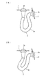
従来、自動車において、車体パネル1と開閉操作されるトランクリッド2との間にワイヤハーネスを架け渡して配索する場合、図4に示すように、防水、防塵を目的としてワイヤハーネスにグロメット3を外装している。本出願人は、特開2001−258129号公報(特許文献1)において、このようなグロメット3を提供しており、該グロメット3は、ワイヤハーネスを挿通する蛇腹筒部3aと、該蛇腹筒部3aの両端に連続させて設けた係止筒部3bからなり、係止筒部3bを車体パネル1とトランクリッド2に穿設した貫通孔に挿入係止している。
2. Description of the Related Art Conventionally, in a car, when a wiring harness is bridged between a
電線を挿通したグロメット3の蛇腹筒部3aは、トランクリッド2を閉鎖した場合には、図5に示すようにU形状に屈曲される。前記グロメット3に挿通する電線本数は、自動車の車種やグレードによって異なり、電線本数が多いと電線の剛性が高いため、図5(A)に示すように、蛇腹筒部3aはU形状に緩やかに屈曲するに対して、電線本数が少ないと電線の剛性が低いため、図5(B)に示すように、U形状に屈曲させた蛇腹筒部3aが屈曲部において大きく屈曲し、その曲率Rが小さくなってしまう場合がある。一方、トランクリッド2を開放すると、電線を挿通したグロメット3の蛇腹筒部3aは直線状となり、トランクリッド2の開閉によって蛇腹筒部3aが曲率Rの小さな屈曲状態と直線状態を繰り返すうちに、グロメット3に挿通した電線が金属疲労を起こして損傷が発生し、ひいては断線が発生する恐れがある。また、グロメット3自体にも損傷が発生する恐れがある。
When the
本発明は前記問題に鑑みてなされたものであり、グロメットに挿通する電線本数にかかわらず、U形状に屈曲するグロメットの蛇腹筒部の屈曲部の曲率Rを大きく維持し、ドアやトランクリッドからなる可動体の開閉によって前記蛇腹筒部が直線状態と屈曲状態を繰り返しても、グロメットに挿通する電線の金属疲労を低減すると共にグロメット自体にも損傷が発生しないようにすることを課題としている。 The present invention has been made in view of the above problems, and maintains a large curvature R of the bent portion of the bellows tube portion of the grommet that bends into a U shape regardless of the number of wires inserted through the grommet. An object of the present invention is to reduce the metal fatigue of the electric wire inserted into the grommet and prevent the grommet itself from being damaged even if the bellows tube portion repeats a linear state and a bent state by opening and closing the movable body.
前記課題を解決するため、本発明は、車体パネルと、該車体パネルとヒンジ結合されるドアあるいはトランクリッドからなる可動体との間に架け渡す電線群に外装する弾性体からなるグロメットにおいて、
長さ方向の両端に前記車体パネルと可動体とにそれぞれ穿設した貫通孔に挿入係止する円環形状の係止溝を備えた大径筒部と、該大径筒部に連続した小径筒部と、該両側の小径筒部の間に連続させて設ける蛇腹筒部とを備え、該蛇腹筒部は前記可動体の閉鎖時にU形状に屈曲されるものであり、
前記蛇腹筒部は全長にわたり大径の山部と小径の谷部とを同一ピッチで交互に連続させていると共に、前記U形状に屈曲された状態で屈曲部の頂点を挟む所要領域では、その肉厚を他の領域より大として屈曲部の曲率を大としていることを特徴とするグロメットを提供している。
In order to solve the above-mentioned problems, the present invention provides a grommet made of an elastic body that covers an electric wire group that spans between a vehicle body panel and a movable body made of a door or a trunk lid that is hinged to the vehicle body panel.
A large-diameter cylindrical portion provided with annular-shaped locking grooves inserted and locked in through holes formed in the vehicle body panel and the movable body at both ends in the length direction, and a small diameter continuous to the large-diameter cylindrical portion, respectively. A cylindrical portion and a bellows cylindrical portion provided continuously between the small-diameter cylindrical portions on both sides, and the bellows cylindrical portion is bent into a U shape when the movable body is closed;
The bellows tube portion has a large-diameter crest and a small-diameter trough alternately arranged over the entire length at the same pitch, and in a required region sandwiching the apex of the bent portion in a state bent to the U shape, There is provided a grommet characterized in that the wall thickness is larger than that of other regions and the curvature of the bent portion is increased.
前記構成によれば、グロメットの蛇腹筒部がU形状に屈曲された状態で、屈曲部の頂点を挟む所要領域における前記蛇腹筒部の肉厚を他の領域よりも大として、屈曲部の曲率Rを大としているため、前記屈曲部の頂点を挟む所要領域における蛇腹筒部の剛性が高められ、蛇腹筒部が大きくアールで屈曲させて、鋭角的な屈曲を防止することができる。よって、ドアやトランクリッドからなる可動体の開閉によって前記グロメットが直線状態と屈曲状態を繰り返しても、グロメットに挿通される電線に発生する金属疲労を低減し、グロメット自体の損傷発生を防止することができる。
また、本発明によれば、蛇腹筒部は全長にわたり大径の山部と小径の谷部とを同一ピッチで交互に連続させつつ、前記のように所要領域の肉厚のみを変化させる構造としているため、グロメットの設計が容易となる。
さらに、このように、所要領域の肉厚を大として、グロメット自体の剛性を高めているため、特に、電線本数が少なく、電線によるグロメットの剛性が高められない場合において、グロメットの屈曲を大きなアールとすることができ、好適に用いられる。
According to the above configuration, in the state where the bellows tube portion of the grommet is bent in a U shape, the thickness of the bellows tube portion in the required region sandwiching the apex of the bend portion is set to be larger than other regions, and the curvature of the bent portion is set. Since R is large, the rigidity of the bellows tube portion in the required region sandwiching the apex of the bent portion can be increased, and the bellows tube portion can be bent with a large radius to prevent acute bending. Therefore, even if the grommet repeats a straight state and a bent state by opening and closing a movable body consisting of a door and a trunk lid, metal fatigue generated in the electric wire inserted through the grommet is reduced, and damage to the grommet itself is prevented. Can do.
Further, according to the present invention, the bellows tube portion has a structure in which only the wall thickness of the required region is changed as described above while the large-diameter crests and the small-diameter troughs are alternately continued at the same pitch over the entire length. Therefore, the grommet can be easily designed.
Further, since the rigidity of the grommet itself is increased by increasing the thickness of the required area in this way, especially when the number of wires is small and the rigidity of the grommet by the wires cannot be increased, the bending of the grommet is greatly increased. And is preferably used.
前記肉厚を大とする領域では、他の領域の肉厚より1.3〜2倍の肉厚としていることが好ましい。
前記のように、肉厚を大とする領域のグロメットの肉厚を、他の領域の肉厚の1.3〜2倍とすることが好ましいのは、肉厚を大とする領域の肉厚が他の領域の肉厚の1.3倍未満であると、屈曲部の曲率を十分に大きくすることができず、挿通する電線の断線防止に十分な効果を発揮できないことによる。一方、肉厚を大とする領域の肉厚が他の領域の肉厚の2倍を超える場合には、グロメットの屈曲部における剛性が高くなりすぎて、ドアやトランクリッドからなる可動体の動きにスムーズに追従できなくなったり、屈曲部における電線挿通空間が小さくなって、グロメットに挿通できる電線本数に制限を受ける恐れがあることに因る。
In the region where the thickness is increased, the thickness is preferably 1.3 to 2 times the thickness of other regions.
As described above, the thickness of the grommet in the region where the thickness is increased is preferably 1.3 to 2 times the thickness of the other region. However, if the thickness is less than 1.3 times the thickness of the other region, the curvature of the bent portion cannot be sufficiently increased, and a sufficient effect for preventing disconnection of the inserted electric wire cannot be exhibited. On the other hand, if the thickness of the area where the wall thickness is large exceeds twice the wall thickness of other areas, the rigidity of the bent part of the grommet will be too high, and the movement of the movable body consisting of the door and trunk lid This is because it may not be possible to smoothly follow, or the wire insertion space in the bent portion may be reduced and the number of wires that can be inserted into the grommet may be limited.
また、前記肉厚を大とする領域では、屈曲部の頂点を最大肉厚とし、その肉厚を両側に向けて次第に薄くしていることが好ましい。
グロメットの屈曲部の頂点は最も大きく屈曲する部分であるので、前記のように、屈曲部の頂点を最大肉厚とすることにより、スムーズに屈曲部の曲率Rを大きくすることができる。一方、屈曲部の頂点を離れるにつれて屈曲の度合いは小さくなるため、このような部分の肉厚を屈曲部の頂点のような大きな肉厚にする必要はなく、前記のように、肉厚を両側に向けて次第に薄くすることでグロメットの重量増加を必要最小限に抑えることができ、グロメットの適度な柔軟性も維持することができる。
Moreover, in the area | region where the said thickness is large, it is preferable to make the vertex of a bending part into the maximum thickness, and to make the thickness gradually thin toward both sides.
Since the vertex of the bent portion of the grommet is the portion that is bent the most, as described above, the curvature R of the bent portion can be increased smoothly by setting the vertex of the bent portion to the maximum thickness. On the other hand, since the degree of bending becomes smaller as the vertex of the bent portion is separated, it is not necessary to make the thickness of such a portion as large as the vertex of the bent portion. By gradually reducing the thickness of the grommet, an increase in the weight of the grommet can be suppressed to a necessary minimum, and an appropriate flexibility of the grommet can be maintained.
さらに、前記肉厚を大とする領域は、U形状に屈曲された状態で、屈曲部の頂点から両側部の中央位置の長さ以下の領域としていることが好ましい。
グロメットがU形状の屈曲された状態における、屈曲部頂点の両側部の中央位置付近は、屈曲の度合いが最も小さくなる部分であるため、この部分の肉厚を大きくする必要はなく、前記のように、肉厚を大とする領域を、U形状に屈曲された状態で、屈曲部の頂点から両側部の中央位置の長さ以下の領域とすることにより、グロメットの適度な柔軟性を維持し、グロメットの重量増加も必要最小限に抑えつつ、屈曲部の曲率Rを大きくして挿通する電線の断線を防止する効果を十分得ることができる。
Furthermore, it is preferable that the region where the thickness is increased is a region which is not longer than the length of the center position on both sides from the apex of the bent portion in a state bent in a U shape.
In the state where the grommet is bent in a U shape, the vicinity of the center position on both sides of the apex of the bent portion is the portion where the degree of bending is the smallest, so there is no need to increase the thickness of this portion. In addition, by keeping the area where the wall thickness is large in a state bent to a U shape, the moderate flexibility of the grommet can be maintained by making the area less than the length of the center position on both sides from the apex of the bent part. In addition, it is possible to sufficiently obtain an effect of preventing the breakage of the inserted wire by increasing the curvature R of the bent portion while suppressing the increase in the weight of the grommet to the minimum necessary.
前記車体パネルの係止側の小径筒部に連続する蛇腹筒部も、U形状に屈曲された状態で両側部の中央位置に達するまでの領域で、その肉厚を前記屈曲部の頂点を挟む領域の肉厚と同様な肉厚とし、かつ、前記小径筒部の肉厚を連続する蛇腹筒部の肉厚以上としていることが好ましい。 The bellows tube portion that is continuous with the small-diameter tube portion on the locking side of the vehicle body panel is also in the region until it reaches the center position of both sides in a state of being bent in a U shape, and sandwiches the apex of the bent portion. It is preferable that the thickness is the same as the thickness of the region, and the thickness of the small diameter cylindrical portion is equal to or greater than the thickness of the continuous bellows cylindrical portion.
従来のグロメットでは、前記したような問題の他に、ドアやトランクリッドを閉鎖することによって、グロメットがU形状に屈曲した場合、車体パネルの係止側の小径筒部に連続する蛇腹筒部が外側へ湾曲しやすく、外側へ湾曲したグロメットと、車体パネルとドアやトランクリッドとの間の限られたスペースに配置された周辺部品とが干渉することによって、グロメットが損傷したり、車両の振動により異音が発生したりするという問題もある。
前記構成によれば、車体パネルの係止側の小径筒部に連続する蛇腹筒部も、U形状に屈曲された状態で両側部の中央位置に達するまでの領域で、その肉厚を前記屈曲部の頂点を挟む領域の肉厚と同様な肉厚としているため、該領域の蛇腹筒部の剛性も高めることができ、グロメットをU形状に屈曲したときに車体パネルとの係止側の蛇腹筒部が外側に大きく湾曲するのを防止することができる。これにより、U形状に屈曲させたグロメットが車体パネル側に配置した周辺部品と干渉するのを防止でき、周辺部品との干渉によるグロメットの損傷や、周辺部品とグロメットが干渉するときに生じる異音の発生を防止することができる。
In the conventional grommet, in addition to the above-described problems, when the grommet is bent into a U shape by closing the door or the trunk lid, the bellows cylinder portion continuous to the small diameter cylinder portion on the locking side of the vehicle body panel is provided. The grommet that is easily bent outward and the outer curved grommet interferes with peripheral parts placed in a limited space between the body panel and the door or trunk lid. There is also a problem that abnormal noise occurs.
According to the above configuration, the bellows tube portion that is continuous with the small-diameter tube portion on the locking side of the vehicle body panel is also bent in the U-shaped region until the center position of both side portions is reached. Since the thickness is similar to the thickness of the region sandwiching the apex of the portion, the rigidity of the bellows tube portion of the region can also be increased, and when the grommet is bent into a U shape, the bellows on the locking side with the vehicle body panel It can prevent that a cylinder part curves greatly outside. As a result, it is possible to prevent the grommet bent in the U shape from interfering with peripheral parts arranged on the vehicle body panel side, damage to the grommet due to interference with the peripheral parts, and abnormal noise generated when the peripheral parts and the grommet interfere with each other. Can be prevented.
また、前記構成によれば、小径筒部の肉厚を連続する蛇腹筒部の肉厚以上としているため、特に大きな力が頻繁にかかる車体パネルとの係止側のグロメット端部の剛性を高めることができ、内部に挿通する電線を確実に保護することができる。 Further, according to the above configuration, since the thickness of the small-diameter cylindrical portion is equal to or greater than the thickness of the continuous bellows cylindrical portion, the rigidity of the end portion of the grommet on the locking side with the vehicle body panel to which particularly large force is frequently applied is increased. It is possible to reliably protect the electric wire inserted inside.
具体的には、前記可動体はトランクリッドからなり、該トランクリッドとヒンジ材を介して連結される車体パネルが、前記U形状に屈曲される蛇腹筒部の外側に位置し、前記蛇腹筒部に肉厚部分を設けて剛性を高め、該蛇腹筒部の外側への湾曲を抑制して前記車体パネルと非接触とされている。
前記構成によれば、U形状に屈曲させたグロメットが外側へ湾曲しないため、車体パネルとトランクリッドとの間の狭スペースにグロメットを配置することができ、グロメットと前記車体パネルとの干渉も防止してグロメットが損傷するのを防止することができる。
Specifically, the movable body is made of a trunk lid, and a vehicle body panel connected to the trunk lid via a hinge member is located outside the bellows tube portion bent into the U shape, and the bellows tube portion A thick portion is provided to increase rigidity, and curving to the outside of the bellows tube portion is suppressed, so that it is not in contact with the vehicle body panel.
According to the above configuration, since the grommet bent in the U shape does not curve outward, the grommet can be disposed in a narrow space between the vehicle body panel and the trunk lid, and interference between the grommet and the vehicle body panel is prevented. Thus, the grommet can be prevented from being damaged.
前述したように、本発明によれば、グロメットの蛇腹筒部がU形状に屈曲された状態で、屈曲部の頂点を挟む所要領域における前記蛇腹筒部の肉厚を他の領域よりも大として、屈曲部の曲率Rを大としているため、前記屈曲部の頂点を挟む所要領域における蛇腹筒部の剛性が高められ、蛇腹筒部の鋭角的な屈曲を防止することができる。よって、グロメットに挿通される電線本数にかかわらず、ドアやトランクリッドからなる可動体の開閉によって前記グロメットが直線状態と屈曲状態を繰り返しても、グロメットに挿通される電線に発生する金属疲労を低減し、グロメット自体の損傷発生を防止することができる。 As described above, according to the present invention, in the state where the bellows tube portion of the grommet is bent in a U shape, the thickness of the bellows tube portion in the required region sandwiching the apex of the bent portion is made larger than that in other regions. Since the curvature R of the bent portion is made large, the rigidity of the bellows tube portion in the required region sandwiching the apex of the bend portion can be increased, and acute bending of the bellows tube portion can be prevented. Therefore, regardless of the number of wires inserted into the grommet, metal fatigue generated on the wires inserted into the grommet can be reduced even if the grommet repeats a straight state and a bent state by opening and closing a movable body consisting of a door and a trunk lid. In addition, damage to the grommet itself can be prevented.
また、前記のように、車体パネルの係止側の小径筒部に連続する蛇腹筒部も、U形状に屈曲された状態で両側部の中央位置に達するまでの領域で、その肉厚を前記屈曲部の頂点を挟む領域の肉厚と同様な肉厚とすることにより、該領域の蛇腹筒部の剛性も高めることができ、グロメットをU形状に屈曲したときに車体パネルとの係止側の蛇腹筒部が外側に大きく湾曲するのを防止することができる。これにより、U形状に屈曲させたグロメットが車体パネル側に配置した周辺部品と干渉するのを防止でき、周辺部品との干渉によるグロメットの損傷や、周辺部品とグロメットが干渉するときに生じる異音の発生を防止することができる。 In addition, as described above, the bellows tube portion that is continuous with the small-diameter tube portion on the locking side of the vehicle body panel also has a thickness in the region until it reaches the center position on both sides in a bent state in the U shape. By making the thickness similar to the thickness of the region sandwiching the apex of the bent portion, the rigidity of the bellows tube portion of the region can also be increased, and when the grommet is bent into a U shape, the side to be locked with the vehicle body panel It is possible to prevent the bellows tube portion from being greatly bent outward. As a result, it is possible to prevent the grommet bent in the U shape from interfering with the peripheral parts arranged on the vehicle body panel side, damage to the grommet due to interference with the peripheral parts, and abnormal noise generated when the peripheral parts and the grommet interfere with each other. Can be prevented.
本発明の実施形態を図面を参照して説明する。
図1乃至図3は、本発明の実施形態を示し、グロメット10は、自動車の車体パネル20と、車体パネル20にヒンジ結合されるトランクリッド21(可動体)との間に架け渡す電線群(図示せず)に外装するものである。
Embodiments of the present invention will be described with reference to the drawings.
1 to 3 show an embodiment of the present invention. A
グロメット10は、EPDM(エチレンプロピレンジエンゴム)等のゴムまたはエラストマーにより一体成形され、長さ方向の両端に車体パネル20とトランクリッド21とにそれぞれ穿設した貫通孔20a、21aに挿入係止する円環形状の係止溝11a、12aを備えた短尺な大径筒部11、12と、該大径筒部11、12に連続した長尺な小径筒部13、14と、該両側の小径筒部13、14の間に連続させて設ける蛇腹筒部15とを備えている。
The
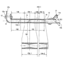
グロメット10の蛇腹筒部15は、全長にわたり大径の山部15aと小径の谷部15bを蛇腹筒部15の長さ方向に同一ピッチで交互に設けて屈曲可能としており、図3に示すように、トランクリッド21の閉鎖時にU形状に屈曲される。なお、本実施形態においては、蛇腹筒部15の非伸長時の全長を18cmとし、山部15aの外径を20mm、ピッチを5mmとしている。
The
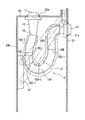
また、図3に示すように、蛇腹筒部15がU形状に屈曲された状態で、屈曲部の頂点15pを挟む所要領域15A−1を他の領域15Bより肉厚を大とする領域とし、屈曲部の曲率Rを大きくしている。本実施形態において、前記屈曲部の頂点15pとなるのは、図1に示す非伸長状態の蛇腹筒部15の、車体パネル20係止側の小径筒部13と蛇腹筒部15との連続部16から7cm離れた点15pであり、この点15pを挟む前記連続部16から5〜9cmの領域を、肉厚を大とする領域15A−1としている。この領域15A−1は、U形状に屈曲された状態で、屈曲部の頂点15pから両側部15C、15Dの中央位置15C−1、15D−1の長さ以下の領域となっている。
また、肉厚を大とする領域15A−1では、屈曲部の頂点15pにおける肉厚を2mmとして最大肉厚とし、両側に向けて肉厚1mmまで次第に薄くしている。
Further, as shown in FIG. 3, in the state where the
Further, in the
また、蛇腹筒部15において、車体パネル20の係止側の小径筒部13と蛇腹筒部15との連続部16から3cmまでの領域も、他の領域15Bより肉厚を大とする領域15A−2とし、この領域15A−2は、U形状に屈曲された状態で、両側部15Cの中央位置15C−1に達するまでの領域としている。この肉厚を大とする領域15A−2では、車体パネル20の係止側の小径筒部13と連続する蛇腹筒部15の肉厚を2mmとして最大肉厚とし、中央位置15C−1側に向けて肉厚1mmまで次第に薄くしている。
蛇腹筒部15においては、前記肉厚を大とする領域15A−1および15A−2以外の領域を他の領域15Bとし、その領域の肉厚を1mm(一定)としている。
Further, in the
In the
蛇腹筒部15の車体パネル20の係止側には、連続する蛇腹筒部15の肉厚より大きな肉厚(5mm)の小径筒部13を連続させて設けており、小径筒部13の中心軸線O2を蛇腹筒部15の中心軸線O1と一致させると共に、小径筒部13の長さを65mmとして長尺とし、小径筒部13の先端に電線群をテープ巻き固定するためのテープ巻き舌片13aを突設している。また、小径筒部13の先端側外周面を囲むように短尺かつ楕円形状の大径筒部11を設けており、大径筒部11の外周面に円環形状の係止溝11aを設けている。大径筒部11の中心軸線O3を小径筒部の軸線O2に対して傾斜させている。
A small diameter
一方、蛇腹筒部15のトランクリッド21の係止側にも小径筒部14を連続させて設けており、小径筒部14は蛇腹筒部15の中心軸線O1に対して略90度屈曲し、屈曲側の先端に楕円形状の大径筒部12を連続させて設けている。大径筒部12の外周面に円環形状の係止溝12aを設けると共に、先端に電線群をテープ巻き固定するためのテープ巻き舌片12bを突設している。
On the other hand, the small-diameter
グロメット10に車体パネル20とトランクリッド21に架け渡す電線群を挿通して両端のテープ巻き舌片13a、12bにテープ巻き固定すると共に、両端の大径筒部11、12の係止溝11a、12aを車体パネル20とトランクリッド21に穿設した貫通孔20a、21aの周縁に嵌合して、車体パネル20とトランクリッド21間にグロメット10を架け渡して取り付けている。
トランクリッド21を車体パネル20に対して開いた状態ではグロメット10の蛇腹筒部15が略直線状に伸長する一方、トランクリッド21を車体パネル20に対して閉鎖した状態では、図3に示すように、蛇腹筒部15がU形状に屈曲した状態となる。この屈曲した蛇腹筒部15のうち車体パネル20への係止側の外側にはトランクリッド21とヒンジ材22を介して連結される車体パネル20の屈曲部20bが配置されている。
The
When the
前記構成によれば、グロメット10の蛇腹筒部15がU形状に屈曲された状態で、屈曲部の頂点15pを挟む所要領域15A−1における蛇腹筒部15の肉厚を他の領域15Bよりも大として、屈曲部の曲率Rを大としているため、屈曲部の頂点15pを挟む所要領域15A−1における蛇腹筒部15の剛性が高められ、蛇腹筒部15の鋭角的な屈曲を防止することができる。よって、グロメット10に挿通される電線本数にかかわらず、トランクリッド21の開閉によってグロメット10が直線状態と屈曲状態を繰り返しても、グロメット10に挿通される電線に金属疲労が発生するのを低減することができる。
According to the said structure, the thickness of the
また、前記のように、車体パネル20の係止側の小径筒部13に連続する蛇腹筒部15も、U形状に屈曲された状態で両側部15Cの中央位置15C−1に達するまでの領域15A−2で、その肉厚を屈曲部の頂点15pを挟む領域15A−1の肉厚と同様な肉厚とすることにより、該領域15A−2の蛇腹筒部15の剛性も高めることができ、グロメット10をU形状に屈曲したときに車体パネル20との係止側の蛇腹筒部15が外側に大きく湾曲するのを防止することができる。これにより、U形状に屈曲させたグロメット10が車体パネル20の屈曲部20bと干渉するのを防止でき、干渉によるグロメット10の損傷や、ヒンジ材22とグロメット10が干渉するときに生じる異音の発生を防止することができる。
In addition, as described above, the
また、このように、所要領域15A−1、15A−2の肉厚を大として、グロメット自体の剛性を高めているため、電線本数が多く剛性が高いワイヤハーネスに限らず、電線本数が少なく剛性が低いワイヤハーネスを挿通することもでき、グロメット10の汎用性を高めることもできる。
なお、本実施形態では、グロメット10を車体パネル20とトランクリッド21との間に取り付けているが、車体パネルとサイドドアやバックドア等のドアとの間に取り付けてもよい。
In addition, since the rigidity of the grommet itself is increased by increasing the thickness of the required
In this embodiment, the
10 グロメット
11、12 大径筒部
11a、12a 係止溝
13、14 小径筒部
15 蛇腹筒部
15a 山部
15b 谷部
15p 屈曲部の頂点
15A−1、15A−2 肉厚を大とする領域
15B 他の領域
15C、15D 両側部
15C−1、15D−1 両側部の中央位置
16 連続部
20 車体パネル
20b 貫通孔
21 トランクリッド(可動体)
21a 貫通孔
22 ヒンジ材
10
21a Through
Claims (6)
長さ方向の両端に前記車体パネルと可動体とにそれぞれ穿設した貫通孔に挿入係止する円環形状の係止溝を備えた大径筒部と、該大径筒部に連続した小径筒部と、該両側の小径筒部の間に連続させて設ける蛇腹筒部とを備え、該蛇腹筒部は前記可動体の閉鎖時にU形状に屈曲されるものであり、
前記蛇腹筒部は全長にわたり大径の山部と小径の谷部とを同一ピッチで交互に連続させていると共に、前記U形状に屈曲された状態で屈曲部の頂点を挟む所要領域では、その肉厚を他の領域より大として屈曲部の曲率を大としていることを特徴とするグロメット。 In a grommet made of an elastic body that covers an electric wire group that spans between a vehicle body panel and a movable body made of a door or a trunk lid that is hinged to the vehicle body panel,
A large-diameter cylindrical portion provided with annular-shaped locking grooves inserted and locked in through holes formed in the vehicle body panel and the movable body at both ends in the length direction, and a small diameter continuous to the large-diameter cylindrical portion, respectively. A cylindrical portion and a bellows cylindrical portion provided continuously between the small-diameter cylindrical portions on both sides, and the bellows cylindrical portion is bent into a U shape when the movable body is closed;
The bellows tube portion has a large-diameter crest and a small-diameter trough alternately arranged over the entire length at the same pitch, and in a required region sandwiching the apex of the bent portion in a state bent to the U shape, A grommet characterized in that the wall thickness is larger than other regions and the curvature of the bent portion is increased.
Priority Applications (3)
| Application Number | Priority Date | Filing Date | Title |
|---|---|---|---|
| JP2006279943A JP4420006B2 (en) | 2006-10-13 | 2006-10-13 | Grommet |
| PCT/JP2007/054393 WO2008044345A1 (en) | 2006-10-13 | 2007-03-07 | Grommet |
| US12/066,285 US7868256B2 (en) | 2006-10-13 | 2007-03-07 | Grommet |
Applications Claiming Priority (1)
| Application Number | Priority Date | Filing Date | Title |
|---|---|---|---|
| JP2006279943A JP4420006B2 (en) | 2006-10-13 | 2006-10-13 | Grommet |
Publications (2)
| Publication Number | Publication Date |
|---|---|
| JP2008099476A JP2008099476A (en) | 2008-04-24 |
| JP4420006B2 true JP4420006B2 (en) | 2010-02-24 |
Family
ID=39282557
Family Applications (1)
| Application Number | Title | Priority Date | Filing Date |
|---|---|---|---|
| JP2006279943A Expired - Fee Related JP4420006B2 (en) | 2006-10-13 | 2006-10-13 | Grommet |
Country Status (3)
| Country | Link |
|---|---|
| US (1) | US7868256B2 (en) |
| JP (1) | JP4420006B2 (en) |
| WO (1) | WO2008044345A1 (en) |
Families Citing this family (11)
| Publication number | Priority date | Publication date | Assignee | Title |
|---|---|---|---|---|
| JP5743138B2 (en) * | 2011-02-16 | 2015-07-01 | トヨタ車体株式会社 | Vehicle door harness cover |
| US8651460B2 (en) * | 2011-06-01 | 2014-02-18 | The Wiremold Company | Wall grommet for power connection |
| US8420943B1 (en) | 2011-11-18 | 2013-04-16 | Nissan North America, Inc. | Wiring grommet with body contact portion |
| US8648259B2 (en) * | 2012-01-12 | 2014-02-11 | Yazaki North America, Inc. | Accordion-style grommet with shape-influencing stiffeners |
| JP5875151B2 (en) * | 2012-03-30 | 2016-03-02 | 矢崎総業株式会社 | Exterior protection member for harness and wire harness using the same |
| JP6024041B2 (en) | 2012-10-31 | 2016-11-09 | 矢崎総業株式会社 | Wire harness |
| JP5999426B2 (en) * | 2012-10-31 | 2016-09-28 | 矢崎総業株式会社 | Wire harness |
| JP5994595B2 (en) | 2012-11-21 | 2016-09-21 | 矢崎総業株式会社 | Wire harness |
| JP6339600B2 (en) * | 2016-01-13 | 2018-06-06 | 古河電気工業株式会社 | Grommet |
| JP6621145B2 (en) * | 2017-08-02 | 2019-12-18 | 住友電装株式会社 | Grommet and wire with grommet |
| JP7133596B2 (en) * | 2020-09-10 | 2022-09-08 | 住友電装株式会社 | Grommet |
Family Cites Families (8)
| Publication number | Priority date | Publication date | Assignee | Title |
|---|---|---|---|---|
| JP3567842B2 (en) * | 2000-03-03 | 2004-09-22 | 住友電装株式会社 | Grommet |
| JP3900782B2 (en) | 2000-03-09 | 2007-04-04 | 住友電装株式会社 | Grommet |
| US6603078B2 (en) * | 2000-09-22 | 2003-08-05 | Sumitomo Wiring Systems, Ltd. | Grommet |
| JP3707399B2 (en) * | 2001-06-18 | 2005-10-19 | 住友電装株式会社 | Grommet with resin inner sleeve |
| JP3709812B2 (en) * | 2001-06-26 | 2005-10-26 | 住友電装株式会社 | Grommet with resin inner sleeve for fixing connector |
| JP2003348736A (en) * | 2002-05-29 | 2003-12-05 | Yazaki Corp | Grommet |
| JP3944067B2 (en) * | 2002-12-04 | 2007-07-11 | 矢崎総業株式会社 | Waterproof grommet |
| JP4221331B2 (en) * | 2004-05-12 | 2009-02-12 | 住友電装株式会社 | Fixing structure of washer tube to grommet |
-
2006
- 2006-10-13 JP JP2006279943A patent/JP4420006B2/en not_active Expired - Fee Related
-
2007
- 2007-03-07 US US12/066,285 patent/US7868256B2/en not_active Expired - Fee Related
- 2007-03-07 WO PCT/JP2007/054393 patent/WO2008044345A1/en active Application Filing
Also Published As
| Publication number | Publication date |
|---|---|
| WO2008044345A1 (en) | 2008-04-17 |
| JP2008099476A (en) | 2008-04-24 |
| US7868256B2 (en) | 2011-01-11 |
| US20100147557A1 (en) | 2010-06-17 |
Similar Documents
| Publication | Publication Date | Title |
|---|---|---|
| JP4420006B2 (en) | Grommet | |
| US7952032B2 (en) | Grommet | |
| JP5365569B2 (en) | Grommet for wiring harness | |
| US20110265286A1 (en) | Grommet | |
| US6339196B1 (en) | Grommet | |
| US8091949B2 (en) | Arrangement structure of door wire harness | |
| JP2012239353A (en) | Grommet | |
| US8237053B2 (en) | Power supply apparatus for slidable structure | |
| US6079764A (en) | Wiring harness arranging construction | |
| JP2007060781A (en) | Flexible protective tube for harness, and wire harness with protective tube | |
| JP5112168B2 (en) | Grommet | |
| US10864864B2 (en) | Grommet and grommet-equipped wire | |
| JP6662826B2 (en) | Corrugated tube and wire harness | |
| JP3678168B2 (en) | Cracked corrugated tube for wire harness exterior | |
| JP2007159337A (en) | Sheath material for wire harnesses | |
| AU2002300704B2 (en) | Grommet | |
| JP2007181268A (en) | Power supply for slide structure | |
| JP6979916B2 (en) | Grommets and wire harnesses with grommets | |
| JPH10148279A (en) | Bellows structure | |
| JPH09301098A (en) | Door grommet | |
| JP7227036B2 (en) | Grommet | |
| WO2021200323A1 (en) | Protector and wire harness | |
| JP2004129371A (en) | Feeder system and harness routing structure | |
| JP2011234578A (en) | Jacket material for wiring harness | |
| JP6080205B2 (en) | Grommet |
Legal Events
| Date | Code | Title | Description |
|---|---|---|---|
| A621 | Written request for application examination |
Free format text: JAPANESE INTERMEDIATE CODE: A621 Effective date: 20081119 |
|
| TRDD | Decision of grant or rejection written | ||
| A01 | Written decision to grant a patent or to grant a registration (utility model) |
Free format text: JAPANESE INTERMEDIATE CODE: A01 Effective date: 20091110 |
|
| A01 | Written decision to grant a patent or to grant a registration (utility model) |
Free format text: JAPANESE INTERMEDIATE CODE: A01 |
|
| A61 | First payment of annual fees (during grant procedure) |
Free format text: JAPANESE INTERMEDIATE CODE: A61 Effective date: 20091123 |
|
| FPAY | Renewal fee payment (event date is renewal date of database) |
Free format text: PAYMENT UNTIL: 20121211 Year of fee payment: 3 |
|
| R150 | Certificate of patent or registration of utility model |
Ref document number: 4420006 Country of ref document: JP Free format text: JAPANESE INTERMEDIATE CODE: R150 Free format text: JAPANESE INTERMEDIATE CODE: R150 |
|
| FPAY | Renewal fee payment (event date is renewal date of database) |
Free format text: PAYMENT UNTIL: 20131211 Year of fee payment: 4 |
|
| LAPS | Cancellation because of no payment of annual fees |