JP4417718B2 - Sieve device - Google Patents
Sieve device Download PDFInfo
- Publication number
- JP4417718B2 JP4417718B2 JP2003547079A JP2003547079A JP4417718B2 JP 4417718 B2 JP4417718 B2 JP 4417718B2 JP 2003547079 A JP2003547079 A JP 2003547079A JP 2003547079 A JP2003547079 A JP 2003547079A JP 4417718 B2 JP4417718 B2 JP 4417718B2
- Authority
- JP
- Japan
- Prior art keywords
- sieve
- sieving
- box
- carrier
- sieve box
- Prior art date
- Legal status (The legal status is an assumption and is not a legal conclusion. Google has not performed a legal analysis and makes no representation as to the accuracy of the status listed.)
- Expired - Lifetime
Links
Images


Classifications
-
- B—PERFORMING OPERATIONS; TRANSPORTING
- B07—SEPARATING SOLIDS FROM SOLIDS; SORTING
- B07B—SEPARATING SOLIDS FROM SOLIDS BY SIEVING, SCREENING, SIFTING OR BY USING GAS CURRENTS; SEPARATING BY OTHER DRY METHODS APPLICABLE TO BULK MATERIAL, e.g. LOOSE ARTICLES FIT TO BE HANDLED LIKE BULK MATERIAL
- B07B1/00—Sieving, screening, sifting, or sorting solid materials using networks, gratings, grids, or the like
- B07B1/28—Moving screens not otherwise provided for, e.g. swinging, reciprocating, rocking, tilting or wobbling screens
-
- B—PERFORMING OPERATIONS; TRANSPORTING
- B07—SEPARATING SOLIDS FROM SOLIDS; SORTING
- B07B—SEPARATING SOLIDS FROM SOLIDS BY SIEVING, SCREENING, SIFTING OR BY USING GAS CURRENTS; SEPARATING BY OTHER DRY METHODS APPLICABLE TO BULK MATERIAL, e.g. LOOSE ARTICLES FIT TO BE HANDLED LIKE BULK MATERIAL
- B07B1/00—Sieving, screening, sifting, or sorting solid materials using networks, gratings, grids, or the like
- B07B1/46—Constructional details of screens in general; Cleaning or heating of screens
- B07B1/48—Stretching devices for screens
- B07B1/485—Devices for alternately stretching and sagging screening surfaces
Abstract
Description
本発明は、請求項1の上位概念に係わるふるい装置に関している。
The present invention relates to a sieving device according to the superordinate concept of
この種のふるい装置においては、ふるいマットが使用されている。これらマットは、ふるい面全体に渡って場所ごとに、緊張と緩和とが繰り返えされる。これは、例えば、横方向に延びたキャリアを使用して、エキセントリック駆動体により互いに関連して揺動されるように設定された、ふるいボックスのような、2つの移動可能に設置された揺動システムにより、機械的になされる。プラスチックのふるいリニアストリップが、この場合、第1のふるいボックスに一端で接続されており、また、第2のふるいボックスの横方向に延びたキャノアに他端で接続されている。これら2つのふるいボックスの、かくして、特定の横方向に延びたキャリアの互いに異なる方向の揺動、により、プラスチックのふるいリニアストリップは、緊張と緩和を交互に生じる。このようにして、ふるわれる物体は、個々のフラクションに分けられる。このような連続した緊張と緩和とによって、ふるいカバーが自身で繰り返しクリーンになり、ふるい分けが難しい物体でも、良好な分離が可能となる。 In this type of sieve device, a sieve mat is used. These mats are repeatedly tensioned and relaxed from place to place over the entire screen. This is because, for example, two movably mounted swings, such as a sieve box, which are set to swing relative to each other by means of an eccentric drive using a laterally extending carrier Made mechanically by the system. A plastic sieving linear strip is in this case connected to the first sieving box at one end and to the laterally extending canoa of the second sieving box at the other end. Due to the swinging of these two sieving boxes, and thus the specific transversely extending carriers, in different directions, the plastic sieving linear strip alternately produces tension and relaxation. In this way, the object to be screened is divided into individual fractions. Such continuous tension and relaxation allows the screen cover to repeatedly clean itself and allows good separation even for objects that are difficult to screen.
しかし、ふるう物体は、揺動によってふるい機の搬送方向の如何なる加速も受けないので、このようなふるい機は、ふるう物体は、重量により搬送されることができるように、比較的大きい傾斜をなして配置されている。 However, since the sieving object is not subject to any acceleration in the direction of conveyance of the sieving machine due to rocking, such sieving machine has a relatively large inclination so that the sieving object can be conveyed by weight Are arranged.
他の既知のふるい機は、横方向に延びたキャリアを備えたふるいボックスを有している。そして、これらキャリアには、横方向に延びたさらなるキャリアを備えた揺動フレームが、弾性的に結合されている。このようなふるい機において、個々のふるいリニアストリップが、ふるいボックスのキャリアに一端で接続され、また、揺動フレームに他端で接続されている。そして、ふるいボックスは、代表的には、不均衡な駆動体の力により駆動されて揺動され、基本揺動システムと称され得る。ふるいボックスの揺動によって、揺動ボックスに弾性的に結合された前記揺動フレームは、揺動システム(マスーばね)の対応したターンで揺動されるようになり、かくして、補助の揺動システムを構成する。ふるいボックスの揺動によって、ふるい分けられる物体は、ふるい機の搬送方向で加速されるようになって、物体は、ふるい機により良好に搬送される。かくして、ふるい機の傾斜された配置が、絶対的に不必要、並びに/もしくは、単に小さい傾斜のみが必要となる。 Another known sieving machine has a sieving box with a laterally extending carrier. These carriers are elastically coupled with a swing frame provided with a further carrier extending in the lateral direction. In such a sieving machine, each sieving linear strip is connected at one end to the carrier of the sieving box and at the other end to the swing frame. The sieve box is typically driven and swung by the force of an unbalanced drive body, and can be referred to as a basic swing system. Due to the swing of the sieve box, the swing frame elastically coupled to the swing box is swung on the corresponding turn of the swing system (mass spring), thus the auxiliary swing system. Configure. By swinging the sieve box, the object to be screened is accelerated in the transport direction of the sieve machine, and the object is better transported by the sieve machine. Thus, a tilted arrangement of the sieve is absolutely unnecessary and / or only a small tilt is required.
ふるい長全体にわたってふるい装置に設置されている前記ふるいマットの交互の緊張と緩和とにより、これらマットは、粒子詰まりや、微小の湿ったふるう物体による塊に対して、自身で繰り返しクリーンにする。 Due to the alternating tension and relaxation of the sieve mats installed in the sieve apparatus over the entire sieve length, these mats repeatedly clean themselves against particle clogging and lumps of fine wet sieve objects.
バナナふるいが、他の例を示している。これは、ふるい面がふるい長全体に渡って幾つかのセクションに分けられており、これらふるい面のセクションの各々は、ふるい機の中で異なった傾斜をなしている。このような構成は、比較的多い供給量が、粒子サイズに応じて分けられており、カットポイントが供給物の最大の粒子に比較的近いのであれば、好ましく選定される。このようなふるい機の効果は、物体が少なく、また少ない物体が、搬送されて、スクリーン布を通る微小フラクションの通過並びにふるい分けによってふるい分けされるけれども、異なる傾斜、かくしてふるい分けされる物体の異なる搬送速度によって、ふるい機の全長にわたって実質的に同じふるう物体のダンプ高さを維持することができることである。ふるう物体の均一なダンピング高さは、有効なふるい分けに対して非常に効果がある。なぜならば、カットポイント近くの粒子のみが、ふるい機の端部に向かうふるい面上でダンプし、スクリーン布のメッシュを通させる可能性を生じさせないからである。 Banana sieve is another example. This is because the screen surface is divided into several sections over the entire screen length, each of the screen surface sections having a different slope in the screen. Such a configuration is preferably selected if a relatively large supply is divided according to particle size and the cut point is relatively close to the largest particle of the feed. The effect of such a sieving machine is that there are fewer objects and fewer objects are transported and screened through the passage of fine fractions through the screen cloth as well as sieving, but with different inclinations and thus different transport speeds of the objects to be screened. By means of this, it is possible to maintain the dump height of substantially the same sieving object over the entire length of the sieving machine. The uniform damping height of the sieving object is very effective for effective sieving. This is because only the particles near the cut point dump on the sieving face towards the end of the sieving machine and do not create the possibility of passing the screen cloth mesh.
この種ふるい機は、例えば、EP0197191,EP1142651並びにWO92/00148により知られている。 Such sieves are known, for example, from EP0197191, EP1142651 and WO92 / 00148.
本発明の目的は、上記2種のふるい機の効果を組み合わせることである。 The object of the present invention is to combine the effects of the two types of sieves.
これは、不均衡な駆動体により揺動されるようにするふるい機では既に既知の方法で、例えば、ふるい機の揺動により駆動される補助の揺動システムが、設置され、また、このようにして、ふるい機に一端が接続され、揺動システムに他端が接続されたふるいマットが、交互に緊張並びに緩和されることで、果たされる。バナナふるいの効果を付加的に果たすために、ふるい機の揺動により駆動される第2の揺動システムが、請求項1の特徴部分に従って設けられている。全て既知のテンションシャフトふるいにおける平面を常に表すふるい面が、新規なふるい機の湾曲平面として、特に、円筒面のセグメントとして設けられている。かくして、このふるい面は、排出側よりも供給側で傾斜が大きい。これは、既知の好ましいテンションシャフトのふるい動に加えて、バナナふるいの効果も与える。さらに、ふるい面のこのような形状によって、ばね部材を設けることによって、補助の揺動システムを与えることが可能である。このことは、テンションシャフトのふるい効果を非常に簡単に果すふるい機の揺動による振り子のような揺動の形態にもたらされ得る。請求項3ないし11の特徴部分は、この種形態の揺動システムの有効な実施の形態に関している。
This is a method already known for sieving machines that are caused to oscillate by an unbalanced drive, for example an auxiliary sway system driven by sieving of the sieving machine is installed, and Thus, the sieve mat, one end of which is connected to the sieving machine and the other end of which is connected to the swinging system, is accomplished by alternately tensioning and relaxing. In order to additionally fulfill the effect of banana sieving, a second swaying system driven by sieving of the sieving machine is provided according to the features of
請求項12は、本発明の目的において効果がある揺動エキサイターの実施の形態に関している。 Claim 12 relates to an embodiment of a rocking exciter that is effective for the purposes of the present invention.
本発明は、添付の図面に基づいて詳細に以下に説明されるであろう。 The present invention will be described in detail below with reference to the accompanying drawings.
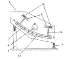
図1は、ふるい機の構成を概略的に示している。この場合、ふるい面1.1,1.2と、これらの間に設けられ、ふるい面を互いに接続する横方向に延びたキャリア1.3とを有するふるいボックスが、ばね部材6によって、ブラケットに支持されている。これら部品は、不均衡な駆動体4により揺動されるようになっている。支持装置1.4が、前記ふるいボックス上に設けられ、上端部に振り子状の構造体のための揺動軸2.2(例えば、シャフト)を有している。この振り子状の構造体は、振り子アーム2.3と、横方向に第2の延びたキャリア2.3のための受入部2.4とを有している。この第2の搬送キャリアは、前記ふるいボックス1に対して移動可能であり、窓状の開口1.6を介してふるいボックスを通る。これら横方向に延びたキャリア1.3,2.3は、これらが、軸が前記揺動軸2.2と対応した円筒面の表面ラインとして理解できるように、位置され得る。ストリップ状のふるいマット3が、横方向に延びたキャリア1.3,2.3間でテンションがかけられている。さらに、ばね部材5aが、ふるいボックス1の基本揺動に対する振り子のような揺動の振幅に影響を与えることができるように、前記ふるいボックス1と、振り子状の構造体2との間に設けられ得る。ふるいボックス1の揺動によって、振り子状の構造体2も、また揺動するように駆動される。デイメンションの適切な選定並びに/もしくはバネ部材の更なる設置によって、振り子状の構造体2の振幅は、影響され得る。このふるい装置は、供給側Aからふるう物体が充填され、ふるわれなかった物体は、装置を排出側Bから排出される。
FIG. 1 schematically shows the structure of a sieving machine. In this case, a sieving box having a sieving surface 1.1, 1.2 and a laterally extending carrier 1.3 provided between them and connecting the sieving surfaces to each other is provided by the
他の実施の形態が図2に示されている。この場合、受け部分2.4は、スペーサ部材7aを介してガイド部材8により案内される。この場合の揺動システムを得るために、複数のばね部材5cを複数のガイド部材に設けるか、図4に示されているように、複数の受け部2.4上に、又はこの近くに位置させる必要がある。複数のばね部材5cが複数のスペーサ部材7a、7bのガイドを支持するために複数のガイド部材8に沿って配置されている。
Another embodiment is shown in FIG. In this case, the receiving portion 2.4 is guided by the guide member 8 via the
さらに、受け部2.4のふるい面1.1並びに/もしくは1.2の外側(図4に概略的に示されている)、もしくは内側(図5に示されている)への位置付けは、異なる機能に応じてなされる。図9は、図5に対応したふるい機を示しているが、これは、不均衡エキサイター4の変わりに、対向したアンバランスウエイトを備えた二重不均衡駆動体を有する既知の構成のリニアーオシレータ4.1が、揺動エキサイターのように、ふるいボックス1に装着されている。かくして、本発明に係わるふるい装置は、テンションシャフトふるいの効果とバナナふるいの効果とを組合せ、ふるうのに困難であった物体のふるい分けに特に適している。
Furthermore, the positioning of the receiving part 2.4 on the sieving surface 1.1 and / or 1.2 on the outside (schematically shown in FIG. 4) or inside (shown in FIG. 5) is: Made according to different functions. FIG. 9 shows a sieving machine corresponding to FIG. 5, which instead of an
Claims (8)
前記ふるい装置は、ふるいボックス(1)を備え、前記ふるいボックス(1)は、前記ふるいボックス(1)の左右のふるい面(1.1,1.2)を繋いでいる水平に横方向に延びた複数の第1のキャリア(1.3)を備えた基本揺動システムとして、駆動体(4)を使用して揺動され、
及び、前記ふるい装置は、補助の揺動システム(2)を備え、前記補助の揺動システム(2)は、前記ふるいボックス(1)に取着され、各々が2つの第1のキャリア(1.3)間に位置され、前記第1のキャリアに対してほぼ平行に位置される水平に横方向に延びた複数の第2のキャリア(2.3)を有し、前記複数の第2のキャリア(2.3)は前記ふるいボックス(1)に関して移動可能であり、それによって前記伸縮可能なふるいマット(3)は前記複数の第1のキャリア(1.3)と前記複数の第2のキャリア(2.3)との間で張力をかけられ、
2つの連続したキャリアにおいては、供給側(A)に近いほうのキャリアは、排出側(B)に近いほうのキャリアよりも高くなっており、2つの連続したキャリア(1.3,2.3)の重心間の高さの相違が、排出側のセクションよりも特定の供給側(B)のセクションで高くなっているような少なくとも2つのセクションを有しているふるい装置において、
前記複数の第2のキャリア(2.3)は、前記ふるいボックス(1)の前記ふるい表面(1.1,1.2)上に設けられた複数の受け部(2.4)によって、これらの端部領域で互いに接続されており、このようにして形成された前記補助の揺動システムは、揺動軸(2.2)に揺動可能に枢支されており、
前記受け部(2.4)は、弾性部材によって前記ふるいボックス(1)に装着されていること、
を特徴とするふるい装置。A sieve device for changing a sieve mat (3), which is a linear elongated strip that can expand and contract,
The sieve device includes a sieve box (1), and the sieve box (1) is horizontally and horizontally connecting the left and right sieve surfaces (1.1, 1.2) of the sieve box (1). As a basic rocking system with a plurality of extended first carriers (1.3), it is swung using a driver (4),
The sieve device includes an auxiliary swing system (2), and the auxiliary swing system (2) is attached to the sieve box (1), each of which includes two first carriers (1 .3) is positioned between, a plurality of second carrier (2.3) extending transversely horizontally to be positioned substantially parallel to said first carrier, a second of said plurality The carrier (2.3) is moveable with respect to the sieve box (1), whereby the extendable sieve mat (3) has the plurality of first carriers (1.3) and the plurality of second Tension is applied to the carrier (2.3),
In the two consecutive carriers, the carrier closer to the supply side (A) is higher than the carrier closer to the discharge side (B), and the two consecutive carriers (1.3, 2.3). In a sieving apparatus having at least two sections where the height difference between the center of gravity is higher in the particular supply side (B) section than in the discharge side section,
Wherein the plurality of second carrier (2.3) is by the sieving front surface (1.1, 1.2) a plurality of receiving portions provided on the sieve box (1) (2.4) Connected to each other in these end regions, the auxiliary oscillating system thus formed is pivotally supported on the oscillating shaft (2.2) ,
The receiving portion (2.4) is attached to the sieve box (1) by an elastic member;
Sieve device characterized by.
Applications Claiming Priority (2)
| Application Number | Priority Date | Filing Date | Title |
|---|---|---|---|
| AT9242001 | 2001-11-29 | ||
| PCT/AT2002/000303 WO2003045587A1 (en) | 2001-11-29 | 2002-10-30 | Sifting device |
Publications (2)
| Publication Number | Publication Date |
|---|---|
| JP2005509519A JP2005509519A (en) | 2005-04-14 |
| JP4417718B2 true JP4417718B2 (en) | 2010-02-17 |
Family
ID=3502957
Family Applications (1)
| Application Number | Title | Priority Date | Filing Date |
|---|---|---|---|
| JP2003547079A Expired - Lifetime JP4417718B2 (en) | 2001-11-29 | 2002-10-30 | Sieve device |
Country Status (13)
| Country | Link |
|---|---|
| US (1) | US7195121B2 (en) |
| EP (1) | EP1480763B1 (en) |
| JP (1) | JP4417718B2 (en) |
| KR (1) | KR100961292B1 (en) |
| CN (1) | CN1256187C (en) |
| AT (1) | ATE327836T1 (en) |
| AU (1) | AU2002342378B2 (en) |
| CA (1) | CA2468075C (en) |
| DE (1) | DE50207040D1 (en) |
| DK (1) | DK1480763T3 (en) |
| ES (1) | ES2266589T3 (en) |
| WO (1) | WO2003045587A1 (en) |
| ZA (1) | ZA200404010B (en) |
Families Citing this family (16)
| Publication number | Priority date | Publication date | Assignee | Title |
|---|---|---|---|---|
| US8436268B1 (en) | 2002-08-12 | 2013-05-07 | Ecullet | Method of and apparatus for type and color sorting of cullet |
| CN100467142C (en) * | 2006-05-09 | 2009-03-11 | 中国矿业大学 | Elastic sieving method and large elastic vibration sieve |
| AU2013388350A1 (en) * | 2013-05-01 | 2015-11-12 | Flsmidth A/S | Vibrating screen |
| DE102013018873B3 (en) * | 2013-11-12 | 2014-11-27 | Schenck Process Gmbh | screening device |
| AT14201U1 (en) * | 2013-11-15 | 2015-05-15 | Binder Co Ag | Screening machine with drive |
| CN103691667A (en) * | 2013-12-31 | 2014-04-02 | 吴江华诚复合材料科技有限公司 | Ceramic capacitor discharge outlet |
| AT517501B1 (en) * | 2015-07-21 | 2017-04-15 | Binder + Co Ag | screening machine |
| DE102016105094A1 (en) * | 2016-03-18 | 2017-09-21 | Cl Schutzrechtsverwaltungs Gmbh | Screening device for the generative production of components |
| CN105863534B (en) * | 2016-06-15 | 2018-12-07 | 成都来宝石油设备有限公司 | The screening plant of oil base drilling fluid solid control equipment based on moving stop |
| CN105863533B (en) * | 2016-06-15 | 2018-12-28 | 四川行之智汇知识产权运营有限公司 | Separate the device of solid-liquid two-phase in drilling mud |
| CN105909192B (en) * | 2016-06-15 | 2018-11-20 | 成都来宝石油设备有限公司 | For sieving the device of oil base drilling fluid solid-liquid two-phase |
| DE102017004508A1 (en) * | 2017-05-11 | 2018-11-15 | Hein, Lehmann Gmbh | Spannwellensiebmaschine |
| CN107321603A (en) * | 2017-08-31 | 2017-11-07 | 徐工集团工程机械有限公司 | Vibratory sieve horizontal limit devices and vibratory sieve |
| CN108380490A (en) * | 2018-04-11 | 2018-08-10 | 河南省振源科技有限公司 | Automatic rotational vibration curved screen of tumbling |
| EP3714996A1 (en) * | 2019-03-29 | 2020-09-30 | Binder + Co AG | Screening device |
| DE102019003163A1 (en) * | 2019-05-06 | 2020-11-12 | Hein, Lehmann Gmbh | Flip-Flow Screening Machine |
Family Cites Families (14)
| Publication number | Priority date | Publication date | Assignee | Title |
|---|---|---|---|---|
| US1693940A (en) * | 1927-04-12 | 1928-12-04 | Robins Conveying Belt Co | Screening apparatus |
| DE1204920B (en) * | 1963-01-05 | 1965-11-11 | Albert Wehner | Sieve or conveyor machine |
| DE1206372B (en) * | 1964-09-26 | 1965-12-09 | Albert Wehner | Screen grate |
| DE2243804A1 (en) | 1972-09-07 | 1974-03-21 | Heves Megyei Tanacsi | Sieving wet sticky material without clogging sieve - using inclined surface with transverse bars, pref with vibration of sieve |
| US4033865A (en) | 1974-12-09 | 1977-07-05 | Derrick Manufacturing Corporation | Non-clogging screen apparatus |
| DE2720173A1 (en) | 1977-05-05 | 1978-11-16 | Derrick Mfg Corp | Non-clogging screen vibrating apparatus - has pair of screen cloths in contact with finer screen on top and supported by coarse mesh |
| DE3221344C1 (en) | 1982-06-05 | 1983-10-27 | Hein, Lehmann AG, 4000 Düsseldorf | Screening machine |
| AT384961B (en) * | 1983-04-11 | 1988-02-10 | Binder Co Ag | SCREEN DEVICE |
| EP0125794A3 (en) | 1983-04-13 | 1985-12-18 | Minpro Pty. Limited | Double rapped sieve screen deck |
| AT379088B (en) * | 1984-02-10 | 1985-11-11 | Binder Co Ag | SCREEN DEVICE |
| DE3512215A1 (en) | 1985-04-03 | 1986-10-16 | Carl Schenck Ag, 6100 Darmstadt | SCREENING MACHINE WITH A FLEXIBLE SCREENING |
| ZA914947B (en) * | 1990-06-29 | 1992-03-25 | Bengston N V | Composite vibratory screen |
| DE10003172C1 (en) * | 2000-01-25 | 2001-06-28 | Joest Gmbh & Co Kg | Sifting device has oscillating carrier frame supporting oscillation frame via coil springs and auxiliary guide elements |
| DE10016979C1 (en) | 2000-04-06 | 2001-08-30 | Joest Gmbh & Co Kg | Sieve device, for sifting damp or sticking material, includes vibrating frame coupled to carrier frame using torsion-rod springs |
-
2002
- 2002-10-30 US US10/497,331 patent/US7195121B2/en not_active Expired - Lifetime
- 2002-10-30 KR KR1020047008135A patent/KR100961292B1/en active IP Right Grant
- 2002-10-30 AU AU2002342378A patent/AU2002342378B2/en not_active Ceased
- 2002-10-30 CA CA2468075A patent/CA2468075C/en not_active Expired - Fee Related
- 2002-10-30 JP JP2003547079A patent/JP4417718B2/en not_active Expired - Lifetime
- 2002-10-30 CN CNB028238133A patent/CN1256187C/en not_active Expired - Lifetime
- 2002-10-30 EP EP02778981A patent/EP1480763B1/en not_active Expired - Lifetime
- 2002-10-30 DK DK02778981T patent/DK1480763T3/en active
- 2002-10-30 WO PCT/AT2002/000303 patent/WO2003045587A1/en active IP Right Grant
- 2002-10-30 AT AT02778981T patent/ATE327836T1/en active
- 2002-10-30 ES ES02778981T patent/ES2266589T3/en not_active Expired - Lifetime
- 2002-10-30 DE DE50207040T patent/DE50207040D1/en not_active Expired - Lifetime
-
2004
- 2004-05-24 ZA ZA2004/04010A patent/ZA200404010B/en unknown
Also Published As
| Publication number | Publication date |
|---|---|
| CA2468075C (en) | 2010-08-24 |
| US7195121B2 (en) | 2007-03-27 |
| KR100961292B1 (en) | 2010-06-04 |
| CN1596158A (en) | 2005-03-16 |
| ES2266589T3 (en) | 2007-03-01 |
| DE50207040D1 (en) | 2006-07-06 |
| AU2002342378A1 (en) | 2003-06-10 |
| ZA200404010B (en) | 2005-08-31 |
| JP2005509519A (en) | 2005-04-14 |
| DK1480763T3 (en) | 2006-10-02 |
| CA2468075A1 (en) | 2003-06-05 |
| ATE327836T1 (en) | 2006-06-15 |
| AU2002342378B2 (en) | 2008-03-06 |
| CN1256187C (en) | 2006-05-17 |
| WO2003045587A1 (en) | 2003-06-05 |
| EP1480763B1 (en) | 2006-05-31 |
| EP1480763A1 (en) | 2004-12-01 |
| US20050077214A1 (en) | 2005-04-14 |
| KR20040062656A (en) | 2004-07-07 |
Similar Documents
| Publication | Publication Date | Title |
|---|---|---|
| JP4417718B2 (en) | Sieve device | |
| US3633745A (en) | Screening machine | |
| US3954604A (en) | Sifting machine | |
| KR830002238B1 (en) | Vibration machine | |
| US20040050757A1 (en) | Multi-deck screening machine | |
| EP3463692A1 (en) | A screening machine for screening material according to size | |
| US2874841A (en) | Oscillatable separator means | |
| CN113795338B (en) | Screening apparatus | |
| US2153243A (en) | Vibratory screen | |
| US3330411A (en) | Screen with spring supported vibratory drive | |
| CN104619432A (en) | Treatment device for free-flowing bulk material | |
| US5456364A (en) | Powered screening apparatus | |
| WO1992000148A1 (en) | Composite vibratory screen | |
| US3770125A (en) | Oscillatory screening apparatus with vertical screen channel | |
| US3179251A (en) | Sieve machine | |
| JPH1043689A (en) | Vibrating screen | |
| US2178813A (en) | Mechano-vibratory apparatus | |
| CN2607203Y (en) | Single-beam exciting screen | |
| EP2603328B1 (en) | Screening apparatus | |
| RU2059449C1 (en) | Sifting device | |
| US3035699A (en) | Resonant oscillatory apparatus | |
| CN112638550B (en) | Relaxation type screening machine | |
| IE20150194A1 (en) | Screen assembly | |
| CN2039601U (en) | Static vibration sieve | |
| CN85107512B (en) | Verticle reinforced screening machine |
Legal Events
| Date | Code | Title | Description |
|---|---|---|---|
| A621 | Written request for application examination |
Free format text: JAPANESE INTERMEDIATE CODE: A621 Effective date: 20050713 |
|
| A977 | Report on retrieval |
Free format text: JAPANESE INTERMEDIATE CODE: A971007 Effective date: 20071011 |
|
| A131 | Notification of reasons for refusal |
Free format text: JAPANESE INTERMEDIATE CODE: A131 Effective date: 20071023 |
|
| A601 | Written request for extension of time |
Free format text: JAPANESE INTERMEDIATE CODE: A601 Effective date: 20080123 |
|
| A602 | Written permission of extension of time |
Free format text: JAPANESE INTERMEDIATE CODE: A602 Effective date: 20080130 |
|
| A521 | Request for written amendment filed |
Free format text: JAPANESE INTERMEDIATE CODE: A523 Effective date: 20080221 |
|
| A131 | Notification of reasons for refusal |
Free format text: JAPANESE INTERMEDIATE CODE: A131 Effective date: 20090602 |
|
| A601 | Written request for extension of time |
Free format text: JAPANESE INTERMEDIATE CODE: A601 Effective date: 20090828 |
|
| A602 | Written permission of extension of time |
Free format text: JAPANESE INTERMEDIATE CODE: A602 Effective date: 20090904 |
|
| A521 | Request for written amendment filed |
Free format text: JAPANESE INTERMEDIATE CODE: A523 Effective date: 20091001 |
|
| TRDD | Decision of grant or rejection written | ||
| A01 | Written decision to grant a patent or to grant a registration (utility model) |
Free format text: JAPANESE INTERMEDIATE CODE: A01 Effective date: 20091027 |
|
| A01 | Written decision to grant a patent or to grant a registration (utility model) |
Free format text: JAPANESE INTERMEDIATE CODE: A01 |
|
| A61 | First payment of annual fees (during grant procedure) |
Free format text: JAPANESE INTERMEDIATE CODE: A61 Effective date: 20091126 |
|
| R150 | Certificate of patent or registration of utility model |
Ref document number: 4417718 Country of ref document: JP Free format text: JAPANESE INTERMEDIATE CODE: R150 Free format text: JAPANESE INTERMEDIATE CODE: R150 |
|
| FPAY | Renewal fee payment (event date is renewal date of database) |
Free format text: PAYMENT UNTIL: 20121204 Year of fee payment: 3 |
|
| FPAY | Renewal fee payment (event date is renewal date of database) |
Free format text: PAYMENT UNTIL: 20121204 Year of fee payment: 3 |
|
| FPAY | Renewal fee payment (event date is renewal date of database) |
Free format text: PAYMENT UNTIL: 20131204 Year of fee payment: 4 |
|
| R250 | Receipt of annual fees |
Free format text: JAPANESE INTERMEDIATE CODE: R250 |
|
| R250 | Receipt of annual fees |
Free format text: JAPANESE INTERMEDIATE CODE: R250 |
|
| R250 | Receipt of annual fees |
Free format text: JAPANESE INTERMEDIATE CODE: R250 |
|
| R250 | Receipt of annual fees |
Free format text: JAPANESE INTERMEDIATE CODE: R250 |
|
| R250 | Receipt of annual fees |
Free format text: JAPANESE INTERMEDIATE CODE: R250 |
|
| R250 | Receipt of annual fees |
Free format text: JAPANESE INTERMEDIATE CODE: R250 |
|
| R250 | Receipt of annual fees |
Free format text: JAPANESE INTERMEDIATE CODE: R250 |
|
| R250 | Receipt of annual fees |
Free format text: JAPANESE INTERMEDIATE CODE: R250 |
|
| R250 | Receipt of annual fees |
Free format text: JAPANESE INTERMEDIATE CODE: R250 |
|
| R250 | Receipt of annual fees |
Free format text: JAPANESE INTERMEDIATE CODE: R250 |
|
| EXPY | Cancellation because of completion of term |