JP4417520B2 - Throw-away drill - Google Patents
Throw-away drill Download PDFInfo
- Publication number
- JP4417520B2 JP4417520B2 JP2000099026A JP2000099026A JP4417520B2 JP 4417520 B2 JP4417520 B2 JP 4417520B2 JP 2000099026 A JP2000099026 A JP 2000099026A JP 2000099026 A JP2000099026 A JP 2000099026A JP 4417520 B2 JP4417520 B2 JP 4417520B2
- Authority
- JP
- Japan
- Prior art keywords
- chip
- drill
- throw
- tip
- drill body
- Prior art date
- Legal status (The legal status is an assumption and is not a legal conclusion. Google has not performed a legal analysis and makes no representation as to the accuracy of the status listed.)
- Expired - Fee Related
Links
Images


Description
【0001】
【発明の属する技術分野】
本発明は、穿孔加工に使用するスローアウェイ式ドリルに関するものである。
【0002】
【従来の技術と課題】
穿孔加工に使用するドリルとして、その全体が一体に形成された通常のソリッド型ドリルの他に、ドリル本体(ホルダー)と別体のスローアウェイチップ上に切削用の刃を形成し、それをドリル本体の先端に、ネジ等によって着脱自在に装着できるようにした、いわゆるスローアウェイ型ドリルがある。
【0003】
このスローアウェイ型ドリルには、2チップ型のものと1チップ型のものとがあり、このうち前者の2チップ型のスローアウェイ型ドリルは、例えば特開平10−29108号公報に記載されているように、穴の中央部を削る内刃を有するチップと、穴の周縁部を削る外刃を有するチップの2つのチップを、ドリル本体の先端に装着することで構成されている。そして上記公報記載の発明では、1つのチップ上に内刃と外刃の両方を形成しておき、ドリル本体に装着する向きと位置とによって同じチップを内刃チップもしくは外刃チップとして兼用できるようにも構成されている。
【0004】
しかし、この2チップ型の構成は、加工径の大きな大型のドリルには適しているものの、例えば加工径がφ10前後よりも小さい小型のドリルにこれを適用しようとすると、ドリル本体の先端にチップ取り付けのためのスペースや、あるいは切屑排出のためのスペースが十分に確保できなかったり、チップ取り付けのためのネジが非常に小さなものとなって十分な取り付け強度が得られなかったりするといった問題があった。
【0005】
一方、前記1チップ型のスローアウェイドリル(以下『1チップドリル』と略称する)としては、例えば特開平10−328918号公報に記載されているように、従来のソリッド型ドリルの先端形状と類似した、穿孔方向に臨み、かつドリルの回転軸上に位置する頂部から、それぞれ両側へ延びる一対の、加工孔の半径の全長に亘る長い刃稜を有するチップを使用したものが一般的である。
【0006】
しかし、上記のチップ形状では、穿孔時にチップに加わる切削抵抗が大きいため、1つのチップを、上記公報の図にみるように2本のネジでもってドリル本体の先端に強固に固定する必要がある上、チップの肉厚を大きくとる必要があり、その分、切屑排出のためのスペースを確保するのが容易でないという問題があった。
【0007】
そこで、発明者は先に、孔の中央部を削る内刃と、孔の周縁部を削る外刃とを、2チップ型のスローアウェイ型ドリルにおける内刃チップの内刃、および外刃チップの外刃の配置と同様の配置として1つのチップ上に形成した、2チップ類似の、1チップ型のスローアウェイチップを開発した(特開平11−188518号公報)。
【0008】
上記2チップ類似の1チップ型スローアウェイチップ(以下『類似1チップ』と略称する)において内刃は、孔の中央部を削るに足る長さを有していれば良く、また外刃も、孔の周縁部を削るに足る長さを有していればよいため、従来の1チップドリルのものに比べて、穿孔時にチップに加わる切削抵抗を低減することができ、内刃および外刃の部分の肉厚を小さくし、ドリル本体への取付けネジを1本として、切屑排出のためのスペースを確保することが可能となった。
【0009】
そこで発明者は、今般、類似1チップおよびそのドリル本体についてさらに検討した結果、上記公報に記載の構造では、特に切刃部分の強度の点と切屑の排出性の点でさらに改善の余地があることを見出した。
【0010】
本発明の目的は、類似1チップに関し、従来に比べて切刃部分の強度が大きく、また、切屑の排出性が向上した、新規なスローアウェイ式ドリルを提供することにある。
【0011】
【課題を解決するための手段及び発明の効果】
本発明者等は切屑の排出性について鋭意検討を加えた結果、切屑の排出方向が何らかの原因で瞬間的に変化し、穴底側へ向かってしまった場合に、この切屑がドリル本体の前逃げ面と穴底との間に入り込むと、切屑の詰まりの原因となることを見出した。
そして、切屑が瞬間的に穴底側へ向かった場合であっても、ドリル本体の前逃げ面と穴底との間に入り込むところまで到達せず、チップポケットによってフルート溝に向けて切屑が案内できる場合には、切屑の排出性は悪化することがないことを見出した。
【0018】
次に、本発明者等は切屑の排出性について鋭意検討を加えた結果、切屑の排出方向が何らかの原因で瞬間的に変化し、穴底側へ向かってしまった場合に、この切屑がドリル本体の前逃げ面と穴底との間に入り込むと、切屑の詰まりの原因となることを見出した。そして、切屑が瞬間的に穴底側へ向かった場合であっても、ドリル本体の前逃げ面と穴底との間に入り込むところまで到達せず、チップポケットによってフルート溝に向けて切屑が案内できる場合には、切屑の排出性は悪化することがないことを見出した。
【0019】
そこで、請求項1の発明は、切刃を前端に形成したスローアウェイチップと、軸状のドリル本体と、このドリル本体の端部に設けられ、スローアウェイチップを挟んで保持する一対の挟持片と、この挟持片の側方に形成された切屑処理面とを備え、上記ドリル本体の少なくとも一方の挟持片前端面に形成した逃げ角のうち、上記切屑処理面に隣接する部分が、他より小さく形成されていることを特徴とするスローアウェイ式ドリルを提供するものである。
【0020】
本構成では、挟持片の端面は、切屑処理面に隣接する部分の逃げ角をその他の部位の逃げ角よりも小さくしたことにより、切屑処理面に隣接する部分側の前逃げ面と穴底との間のスペースを小さくした。これにより、ドリル本体の端面と穴底との間に切屑が入り込んでしまうことを防止する。
【0021】
請求項2の発明は、請求項1において、挟持片端面に形成した逃げ角のうち、切屑処理面に隣接した部分が0〜5°の範囲内であることを特徴とするものである。
【0022】
本構成では、ドリル本体が穴底と干渉することなく切刃の強度を向上させ、かつ、切屑の排出性を良好なものとする効果が顕著となる。
【0023】
【発明の実施の形態】
本発明の好ましい実施の形態を添付図面を参照しつつ説明する。
【0024】
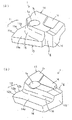
図1(a)および(b)は本発明の一実施の形態のスローアウェイ式ドリルの分解斜視図であり、図1(a)はチップの正面側から見た分解斜視図であり、図1(b)はチップの背面側から見た分解斜視図である。
【0025】
これらの図を参照して、スローアウェイチップ1は、穿孔方向の前端に穴の中央部を削る内刃11と、穴の周縁部を削る外刃12とを形成している。スローアウェイチップ1は、内刃11を形成する板状の第1のブロック13と、外刃12を形成する板状の第2のブロック14とを一体に形成したものである。
【0026】
第1のブロック13と第2のブロック14とは、互いに重なり合う部分15を残して、その板面方向に相互にずらされたような形状をなしている。上記の重なり合う部分15での板厚方向に貫通する貫通孔1aが形成されている。この貫通孔1aはチップ1をドリル本体2に取り付けるための取付ねじ3を挿通させるためのものである。
【0027】
チップ1は互いに背中合わせの2表面(すなわち、各ブロック13、14の外側の表面に相当)に、一対の被挟持面としての第1の座面1bおよび第2の座面1cを形成しており、上記の貫通孔1aはこれら第1および第2の座面1b,1cに開口している。
【0028】
図2を参照して、チップ1は、ドリル本体2の穿孔方向の後部に設けられたポケット23の底により受けられる後部座面1dとを備える。また、チップ1は、内刃11を備える第1ブロック13の後端隅部に一対の被挟持座面1b,1cの間に連続する切り欠き凹部1gを有する
一方、ドリル本体の側面図である図3(a)、および取付ねじ3にてチップ1を取り付けた状態のドリル本体の別角度からの側面図である図3(b)を参照して、ドリル本体2は軸状のドリル本体4とシャンク5とを同軸上に設けており、シャンク5の周面の一部には、当該ドリル本体2がツールホルダ(図示せず)に取り付けられたときに回り止めの働きをする平坦面5aが形成されている。
【0029】
図1(a)および(b)並びに図2(a)を参照して、ドリル本体4の前端にはチップ1を挟んで挟持するための一対の挟持片21,22が形成されており、これら一対の挟持片21,22の挟持面26,27間に、チップ1を挿入するためのポケットが区画されている。このポケット23にチップ1を挿入した状態で、取付ねじ3を挟持片21の貫通孔21aおよび貫通孔1aに挿通させ、挟持片22のねじ孔22aにねじ込むことにより、チップ1がドリル本体2に挟持固定される。
【0030】
一方の挟持片21は内刃11を形成する第1のブロック13に対応して、その挟持面26が第1のブロック13としての第1の座面1bに当接する。他方の挟持片22は外刃12を形成する第2のブロック14に対応して、その挟持面27が第2のブロック14の被挟持面としての第2の座面1cに当接する。そして、前記挟持片21、22の側方には、切屑処理のための切屑処理面21b,22bが形成されている。
【0031】
また、ドリル本体の周面には、穿孔加工時の切屑を加工穴の外へ排出するためのらせん状のフルート溝24,25が形成されている。
【0032】
さらに、シャンク5の端部からドリル本体の基端部にかけて、その中心を貫くようにして冷却液を流す孔からなる大径の第1の通液孔6が形成され、また、この第1の通液孔6に連通して、ドリル本体の基端部からポケット23の底にまで達する挟持片21の挟持面26には、上記第2の通液孔7に連通し、挟持片21の基端から先端まで達する断面片円弧状をなす通液溝8が形成されている。
【0033】
前記通液溝8は、チップ1の前記切り欠き凹部1gと重なるようになっており、この切り欠き凹部1gを通液路とし、冷却液を切屑排出用の内刃側フルート溝24内に排出する[図1(b)参照]ことができる。そして、内刃側フルート24溝内に冷却液を排出することにより、傘状に重なって形成され、排出性があまり良くない内刃からの切屑を確実に孔外に排出させることが可能となる。
【0034】
ところで、本発明の重要な特徴は、スローアウェイ式ドリルを構成するチップの前逃げ面の構成に特徴を持たせたことにより、刃先の強度と切屑の排出性を向上させたことである。以下、それら特徴について説明する。
【0035】
図1のI−I断面図である図4、II−II断面図である図5を参照して、チップ1は、前記内刃11の前逃げ角α1が外刃12の前逃げ角α2よりも大きい。
【0036】
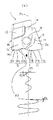
この点について以下説明する。チップ1の内刃11は前逃げ角α1を大きくする必要がある。これは、切刃上の特定のポイントについて加工中の軌跡(螺旋運動軌跡)の穿孔方向角度が内側ほど大きくなるためである。これに対して、外刃12は前記切刃上の特定のポイントについて加工中の軌跡(螺旋運動軌跡)の穿孔方向角度が外側ほど大きいので内刃に比べて前逃げ角が小さくても良い。例えば、図6を参照して、穿孔加工時の内刃のポイントP1において螺旋運動軌跡L1における、穿孔方向に対する角度β1は、外刃のポイントP2の螺旋運動軌跡L2における、穿孔方向に対する角度β2よりも小さく、そのため、内刃11側では穴底面との干渉を避けるため、大きな逃げ角が必要となり、他方、外刃12側では相対的に小さな逃げ角でも良い。
【0037】
そこで、本発明では、この点に着眼し、前記内刃11の前逃げ角α1より外刃12の前逃げ角を小さくしたことにより、刃先角度を大きくしたことを重要な特徴とする。これにより、コーナー部を有する外刃12の強度を向上させることができる。
【0038】
前記内刃の前逃げ角α1と、外刃の前逃げ角α2は、α1>α2の関係である限り、特に大きさが限定されるものではないが、内刃の前逃げ角α1が9〜12°、外刃の前逃げ角α2が6〜10°の範囲内であることが好ましい。
【0039】
前記内刃の前逃げ角α1が9°未満の場合、穴底との干渉が起こりやすい傾向があり、他方、12°を超えると、切刃の強度が小さくなる傾向がある。また、外刃の前逃げ角α2が6°未満の場合、穴底との干渉が起こりやすい傾向があり、他方、10°を超えると、切刃の強度が小さくなる傾向がある。
【0040】
また、本発明は特にドリル本体の端面の逃げ角につい着眼し、下記構成により、切屑の排出性を向上させることを可能としたものである。以下にその特徴を具体的に説明する。
【0041】
図1のIII−III断面図である図7、IV−IV断面図である図8を参照して、挟持片21、22の端面は、切屑処理面21b,22bに隣接する部位の逃げ角γ1がその他の部位の逃げ角γ2よりも小さい。前記チップ1は、このような構成により、切屑が瞬間的に穴底側へ向かった場合であっても、ドリル本体2の端面と穴底との間に入り込むことが防止される。したがって、切屑の排出性が良好なものである。
【0042】
前記切屑処理面21b,22bに隣接する部位の逃げ角γ1と、その他の部位の逃げ角γ2は、γ1<γ2の関係である限り、特に大きさが限定されるものではないが、切屑処理面21b,22bに隣接する部位の逃げ角γ1が0°〜5の範囲内であることが好ましい。前記切屑処理面21b,22bに隣接する部位の逃げ角γ1が0°未満の場合、穴底との干渉が起こりやすい傾向があり、他方、5°を超えると、ドリル本体2の端面と穴底との間に切屑が入り込みやすくなる傾向がある。
【0043】
なお、端面をこのような構成にするのは、挟持片21、22の両方でなくても良く、片方のみであっても構わない。
【0044】
次に、本実施形態のスローアウェイ式ドリルが有するその他の特徴について説明する。
【0045】
図1のV−V断面図である図9を参照して、ドリル本体2の前記内刃側フルート溝24の断面形状は、2円弧形状に形成している。これにより、傘状に重なって形成され、排出性があまり良くない内刃からの切屑が、どちらか1つの円弧に緩やかに嵌合し、ドリル本体の径方向の揺れが小さく、排出されていくので、切屑の詰まりを発生し難くすることが可能となる。
【0046】
また、図3を参照して、前記ドリル本体2は、外刃側切屑処理面21bの上稜線27を外刃側フルート溝25の上稜線25aの最っとも穿孔方向寄りの点Nよりも外側に張り出させたものである。これにより、外刃側切屑処理面21bの上方部分に、屋根(張出部分)が形成されることにより、切屑の径が大きくなり過ぎることを抑制できる。これにより、切屑の排出性を良好とすることが可能である。
【0047】
前記張出量wは、特に限定されるものではないが、特に0.5〜1.2mmの範囲内であることが好ましい。wが0.5mm未満では、切屑の径を小さくする作用が弱く、他方、1.2mmより大きいと切屑の排出性が悪化する傾向がある。
【0048】
なお、本発明のスローアウェイ式ドリルの構成は、以上で説明した図の例に限定されるものではなく、本発明の要旨を変更しない範囲で適宜、設計変更を施すことができる。
【図面の簡単な説明】
【図1】本発明の一実施形態にかかるスローアウェイ式ドリルの分解斜視図であり、(a)はチップの背面側から見た図、(b)はチップの正面側から見た図である。
【図2】同図(a)は上記チップ1の正面側から見た斜視図、同図(b)は背面側から見た斜視図である。
【図3】同図(a)は、上記スローアウェイチップ用ドリルの正面図、同図(b)は上記ドリルホルダーの側面図である。
【図4】図1のI−I断面図である。
【図5】図1のII−II断面図である。
【図6】図1のチップについて、切刃の特定ポイントにおける加工中の螺旋運動の態様を示すための説明図である。
【図7】図1のIII−III断面図である。
【図8】図1のVI−VI断面図である。
【図9】図1のV−V断面図である。
【符号の説明】
1 チップ
2 ドリル本体
1a 貫通孔
11 内刃
12 外刃
21、22 挟持片
24、25 フルート溝
21b,22b 切屑処理面[0001]
BACKGROUND OF THE INVENTION
The present invention relates to a throw-away drill used for drilling.
[0002]
[Prior art and issues]
As a drill used for drilling, in addition to a normal solid type drill that is integrally formed as a whole, a cutting blade is formed on the drill body (holder) and a separate throw-away tip and drilled. There is a so-called throw-away type drill that can be detachably attached to the tip of the main body with a screw or the like.
[0003]
This throw-away type drill is classified into a two-chip type and a one-chip type. Among these, the former two-chip type throw-away type drill is described in, for example, Japanese Patent Laid-Open No. 10-29108. As described above, two tips, that is, a tip having an inner blade that cuts the central portion of the hole and a tip having an outer blade that cuts the peripheral portion of the hole are mounted on the tip of the drill body. In the invention described in the above publication, both the inner blade and the outer blade are formed on one tip, and the same tip can be used as the inner blade tip or the outer blade tip depending on the orientation and position of mounting on the drill body. It is also configured.
[0004]
However, although this two-chip type configuration is suitable for a large drill having a large machining diameter, for example, if this is applied to a small drill having a machining diameter smaller than about φ10, a tip is inserted at the tip of the drill body. There is a problem that sufficient space for mounting or chip discharge cannot be secured, or the screws for chip mounting are very small and sufficient mounting strength cannot be obtained. It was.
[0005]
On the other hand, the one-chip type throw-away drill (hereinafter referred to as “one-chip drill”) is similar to the tip shape of a conventional solid-type drill as described in, for example, Japanese Patent Laid-Open No. 10-328918. In general, a chip using a pair of tips having a long edge over the entire length of the radius of the processing hole, which extends in the drilling direction and extends from the top located on the rotation axis of the drill to both sides, is generally used.
[0006]
However, since the cutting force applied to the tip during drilling is large in the above-described tip shape, it is necessary to firmly fix one tip to the tip of the drill body with two screws as shown in the drawing of the above publication. In addition, there is a problem that it is not easy to secure a space for chip discharge correspondingly because it is necessary to increase the thickness of the chip.
[0007]
Therefore, the inventor first determines the inner blade for cutting the center portion of the hole and the outer blade for cutting the peripheral edge portion of the hole, and the inner blade of the inner blade tip and the outer blade tip of the two-chip type throwaway drill. A one-chip type throw-away tip similar to a two-chip type formed on a single chip in the same arrangement as the outer cutter has been developed (Japanese Patent Laid-Open No. 11-188518).
[0008]
In the one-chip type throw-away tip similar to the above-mentioned two tips (hereinafter abbreviated as “similar one-chip”), the inner blade only needs to have a length sufficient to cut the center of the hole, and the outer blade also has Since it suffices to have a length sufficient to cut the peripheral edge of the hole, it is possible to reduce the cutting resistance applied to the chip during drilling compared to the conventional one-chip drill, and the inner and outer blades It became possible to secure a space for chip discharge by reducing the thickness of the part and using one screw for attaching to the drill body.
[0009]
Therefore, as a result of further examination of the similar one tip and its drill body, the inventor has room for further improvement in the structure described in the above publication, particularly in terms of strength of the cutting edge portion and chip dischargeability. I found out.
[0010]
It is an object of the present invention to provide a novel throw-away drill that relates to a similar tip and that has a stronger cutting edge than conventional ones and improved chip discharge performance.
[0011]
[Means for Solving the Problems and Effects of the Invention]
As a result of diligent investigations on chip discharge performance, the present inventors have found that if the chip discharge direction changes instantaneously for some reason and moves toward the bottom of the hole, the chips will escape to the front of the drill body. It has been found that entering between the surface and the bottom of the hole causes clogging of chips.
Even if the chips momentarily go to the bottom of the hole, they do not reach the point where they enter between the front clearance surface of the drill body and the bottom of the hole, and the chips guide the flute toward the flute groove by the tip pocket. It has been found that chip evacuation does not deteriorate if possible.
[0018]
Next, as a result of intensive studies on the chip discharge performance, the present inventors have found that when the chip discharge direction changes instantaneously for some reason and moves toward the bottom of the hole, It has been found that entering between the front flank and the bottom of the hole may cause clogging of chips. Even if the chips momentarily go to the bottom of the hole, they do not reach the point where they enter between the front clearance surface of the drill body and the bottom of the hole, and the chips guide the flute toward the flute groove by the tip pocket. It has been found that chip evacuation does not deteriorate if possible.
[0019]
Accordingly, the invention of
[0020]
In this configuration, the end face of the sandwiching piece has a clearance angle of the portion adjacent to the chip treatment surface smaller than the clearance angle of the other part, so that the front clearance surface and the hole bottom on the part side adjacent to the chip treatment surface The space between was made smaller. This prevents chips from entering between the end face of the drill body and the hole bottom.
[0021]
According to a second aspect of the present invention, in the first aspect, of the clearance angle formed on the end face of the sandwiching piece, a portion adjacent to the chip treatment surface is within a range of 0 to 5 °.
[0022]
In this structure, the effect which improves the intensity | strength of a cutting blade without making a drill main body interfere with a hole bottom, and makes the discharge property of a chip favorable is remarkable.
[0023]
DETAILED DESCRIPTION OF THE INVENTION
Preferred embodiments of the present invention will be described with reference to the accompanying drawings.
[0024]
1 (a) and 1 (b) are exploded perspective views of a throw-away drill according to an embodiment of the present invention, and FIG. 1 (a) is an exploded perspective view as seen from the front side of the tip. (B) is the disassembled perspective view seen from the back side of the chip | tip.
[0025]
With reference to these drawings, the throw-away
[0026]
The
[0027]
The
[0028]
Referring to FIG. 2, the
[0029]
Referring to FIGS. 1 (a) and 1 (b) and FIG. 2 (a), a pair of sandwiching
[0030]
One
[0031]
In addition,
[0032]
Furthermore, a large-diameter first
[0033]
The liquid groove 8 overlaps with the
[0034]
By the way, an important feature of the present invention is that the strength of the cutting edge and the chip dischargeability are improved by providing a feature in the configuration of the front clearance surface of the tip constituting the throw-away drill. Hereinafter, these features will be described.
[0035]
Referring to FIG. 4 which is a sectional view taken along the line II of FIG. 1 and FIG. 5 which is a sectional view taken along the line II-II, the
[0036]
This point will be described below. The
[0037]
Therefore, in the present invention, focusing on this point, it is an important feature that the blade edge angle is increased by making the front clearance angle of the
[0038]
The size of the front clearance angle α1 of the inner blade and the front clearance angle α2 of the outer blade is not particularly limited as long as the relationship α1> α2, but the front clearance angle α1 of the inner blade is 9˜. It is preferable that the front clearance angle α2 of the outer blade is within a range of 6 ° to 10 °.
[0039]
When the front clearance angle α1 of the inner blade is less than 9 °, interference with the hole bottom tends to occur, and when it exceeds 12 °, the strength of the cutting blade tends to decrease. Further, when the front clearance angle α2 of the outer blade is less than 6 °, there is a tendency that interference with the hole bottom tends to occur. On the other hand, when it exceeds 10 °, the strength of the cutting blade tends to decrease.
[0040]
In addition, the present invention pays particular attention to the clearance angle of the end face of the drill body, and it is possible to improve the chip dischargeability by the following configuration. The features will be specifically described below.
[0041]
Referring to FIG. 7 which is a sectional view taken along the line III-III in FIG. 1 and FIG. 8 which is a sectional view taken along the line IV-IV, the end faces of the sandwiching
[0042]
The clearance angle γ1 of the portion adjacent to the chip treatment surfaces 21b and 22b and the relief angle γ2 of other portions are not particularly limited as long as the relationship of γ1 <γ2, but the chip treatment surface is not limited. It is preferable that the clearance angle γ1 of the portion adjacent to 21b and 22b is in the range of 0 ° to 5. When the clearance angle γ1 of the portion adjacent to the chip-treated
[0043]
In addition, it is not necessary to have both of the sandwiching
[0044]
Next, other features of the throw-away drill of this embodiment will be described.
[0045]
Referring to FIG. 9 which is a VV sectional view of FIG. 1, the sectional shape of the inner blade
[0046]
Referring to FIG. 3, the
[0047]
The overhang amount w is not particularly limited, but is preferably in the range of 0.5 to 1.2 mm. If w is less than 0.5 mm, the effect of reducing the chip diameter is weak, while if it is greater than 1.2 mm, the chip discharge tends to deteriorate.
[0048]
The configuration of the throw-away drill according to the present invention is not limited to the example of the drawings described above, and can be appropriately changed in design without changing the gist of the present invention.
[Brief description of the drawings]
FIG. 1 is an exploded perspective view of a throw-away drill according to an embodiment of the present invention, where (a) is a view seen from the back side of the tip, and (b) is a view seen from the front side of the tip. .
2A is a perspective view seen from the front side of the
FIG. 3 (a) is a front view of the above throwaway tip drill, and FIG. 3 (b) is a side view of the drill holder.
4 is a cross-sectional view taken along the line II of FIG.
5 is a cross-sectional view taken along the line II-II in FIG.
6 is an explanatory diagram for illustrating a mode of spiral movement during processing at a specific point of the cutting edge with respect to the chip of FIG. 1; FIG.
7 is a cross-sectional view taken along the line III-III of FIG.
8 is a sectional view taken along line VI-VI in FIG.
9 is a cross-sectional view taken along the line VV in FIG.
[Explanation of symbols]
DESCRIPTION OF
Claims (4)
上記ドリル本体の少なくとも一方の挟持片前端面に形成した逃げ角のうち、上記切屑処理面に隣接する部分が、他より小さく形成されていることを特徴とするスローアウェイ式ドリル。A throw-away tip with a cutting edge formed at the front end, a shaft-shaped drill body, a pair of clamping pieces provided at the end of the drill body and holding the throw-away tip, and to the sides of the clamping piece A formed chip disposal surface,
A throw-away drill characterized in that, of the clearance angle formed on the front end face of at least one sandwiching piece of the drill body, a portion adjacent to the chip treatment surface is formed smaller than the other.
前記第一のブロックと他方のブロックとの間及び、前記第二のブロックと一方のブロックの間には、切屑排出用スペースが設けられていることを特徴とする請求項1又は請求項2に記載のスローアウェイ式ドリル。The throw-away tip includes an inner blade and a first block corresponding to one clamping piece, and an outer blade and a second block corresponding to the other clamping piece,
3. A chip discharge space is provided between the first block and the other block and between the second block and the one block. Suroawe Lee drill described.
Priority Applications (1)
| Application Number | Priority Date | Filing Date | Title |
|---|---|---|---|
| JP2000099026A JP4417520B2 (en) | 2000-03-31 | 2000-03-31 | Throw-away drill |
Applications Claiming Priority (1)
| Application Number | Priority Date | Filing Date | Title |
|---|---|---|---|
| JP2000099026A JP4417520B2 (en) | 2000-03-31 | 2000-03-31 | Throw-away drill |
Publications (3)
| Publication Number | Publication Date |
|---|---|
| JP2001277022A JP2001277022A (en) | 2001-10-09 |
| JP2001277022A5 JP2001277022A5 (en) | 2007-06-14 |
| JP4417520B2 true JP4417520B2 (en) | 2010-02-17 |
Family
ID=18613426
Family Applications (1)
| Application Number | Title | Priority Date | Filing Date |
|---|---|---|---|
| JP2000099026A Expired - Fee Related JP4417520B2 (en) | 2000-03-31 | 2000-03-31 | Throw-away drill |
Country Status (1)
| Country | Link |
|---|---|
| JP (1) | JP4417520B2 (en) |
Families Citing this family (2)
| Publication number | Priority date | Publication date | Assignee | Title |
|---|---|---|---|---|
| DE102006044605A1 (en) * | 2006-09-19 | 2008-03-27 | Komet Group Holding Gmbh | Indexable insert and use of the indexable insert in a solid drill |
| EP3401043B1 (en) * | 2017-05-11 | 2020-03-25 | Sandvik Intellectual Property AB | Drill body and drill |
-
2000
- 2000-03-31 JP JP2000099026A patent/JP4417520B2/en not_active Expired - Fee Related
Also Published As
| Publication number | Publication date |
|---|---|
| JP2001277022A (en) | 2001-10-09 |
Similar Documents
| Publication | Publication Date | Title |
|---|---|---|
| BRPI0609780A2 (en) | orbital milling tool | |
| JP4558884B2 (en) | Drill throw-away tip and drill | |
| JP4494582B2 (en) | Throw-away tip and throw-away tip holder | |
| US20060159535A1 (en) | Spade Drill Insert Having Helical Margins | |
| JP4949890B2 (en) | Cutting insert, throw-away drill and cutting method of work material | |
| JP4417520B2 (en) | Throw-away drill | |
| EP1682294B1 (en) | Drill insert having helical margins | |
| JP4565770B2 (en) | Throw-away drill | |
| JP4369593B2 (en) | Throw-away drill | |
| JP2003048110A (en) | Boring tool | |
| JP4144866B2 (en) | Throw-away drilling tool | |
| JP2001277024A (en) | Throwaway type drill | |
| JPH11291102A (en) | Throw-away tip and throw-away-type drilling tool with throw-away tip mounted thereon | |
| JP2002283119A (en) | Throwaway tip for ball end mill | |
| JP4020507B2 (en) | Twist drill | |
| JP3166650B2 (en) | Indexable drilling tools | |
| JP2003094220A (en) | Drilling tool | |
| JP3201036B2 (en) | Positive throwaway tip | |
| JPS6125935Y2 (en) | ||
| JP2010110847A (en) | Insert type drill | |
| JP2007061990A (en) | Throw-away type tool | |
| JP2002254230A (en) | Throwaway type drill | |
| JP4514887B2 (en) | Throw away insert for drill and cutting tool using the same | |
| JP2002166316A (en) | Drilling tool | |
| JP4081998B2 (en) | Throw-away insert for drilling and throw-away drilling tool |
Legal Events
| Date | Code | Title | Description |
|---|---|---|---|
| A621 | Written request for application examination |
Free format text: JAPANESE INTERMEDIATE CODE: A621 Effective date: 20070213 |
|
| A521 | Written amendment |
Free format text: JAPANESE INTERMEDIATE CODE: A523 Effective date: 20070423 |
|
| A131 | Notification of reasons for refusal |
Free format text: JAPANESE INTERMEDIATE CODE: A131 Effective date: 20090804 |
|
| A521 | Written amendment |
Free format text: JAPANESE INTERMEDIATE CODE: A523 Effective date: 20091005 |
|
| TRDD | Decision of grant or rejection written | ||
| A01 | Written decision to grant a patent or to grant a registration (utility model) |
Free format text: JAPANESE INTERMEDIATE CODE: A01 Effective date: 20091029 |
|
| A01 | Written decision to grant a patent or to grant a registration (utility model) |
Free format text: JAPANESE INTERMEDIATE CODE: A01 |
|
| A61 | First payment of annual fees (during grant procedure) |
Free format text: JAPANESE INTERMEDIATE CODE: A61 Effective date: 20091126 |
|
| R150 | Certificate of patent or registration of utility model |
Ref document number: 4417520 Country of ref document: JP Free format text: JAPANESE INTERMEDIATE CODE: R150 Free format text: JAPANESE INTERMEDIATE CODE: R150 |
|
| FPAY | Renewal fee payment (event date is renewal date of database) |
Free format text: PAYMENT UNTIL: 20121204 Year of fee payment: 3 |
|
| FPAY | Renewal fee payment (event date is renewal date of database) |
Free format text: PAYMENT UNTIL: 20131204 Year of fee payment: 4 |
|
| LAPS | Cancellation because of no payment of annual fees |