JP4414074B2 - Outer insulation construction method - Google Patents
Outer insulation construction method Download PDFInfo
- Publication number
- JP4414074B2 JP4414074B2 JP2000241840A JP2000241840A JP4414074B2 JP 4414074 B2 JP4414074 B2 JP 4414074B2 JP 2000241840 A JP2000241840 A JP 2000241840A JP 2000241840 A JP2000241840 A JP 2000241840A JP 4414074 B2 JP4414074 B2 JP 4414074B2
- Authority
- JP
- Japan
- Prior art keywords
- heat insulating
- insulating material
- nail
- construction method
- contact
- Prior art date
- Legal status (The legal status is an assumption and is not a legal conclusion. Google has not performed a legal analysis and makes no representation as to the accuracy of the status listed.)
- Expired - Fee Related
Links
Images


Landscapes
- Building Environments (AREA)
Description
【0001】
【発明の属する技術分野】
本発明は、建物の外張断熱工法の施工方法に関するものであり、詳しくは、軸組材の外面に構造用面材を組み付け、前記面材の外側に断熱材を敷設する場合の施工方法に関する。そして、この施工方法の適用出来うる建物の例としては、在来木造の軸組工法の建物、および、ツーバイフォー等の木造の枠組壁工法およびスチールハウスの鉄骨枠組壁工法等の建物が考えられる。
【0002】
【従来の技術】
近年、省エネルギーおよび居住の快適性の観点から、建物の床、壁、天井、屋根下地部に断熱材を敷設することが普及してきている。そして、戸建の建築物の壁部を対象とした場合の断熱方法としては軸間断熱工法と外張断熱工法が広く知られている。一方、省エネルギー基準の数回の改訂を経て施行された次世代省エネルギー基準では、断熱材の厚みを全般的に以前の基準より更に厚くする規定がなされていて、適用地域によっては軸間断熱工法では納まらない断熱材の厚み必要とされているとともに、軸間断熱工法より結露問題の可能性が小さく室内温度のばらつき少なくなりうる外張断熱工法が例示されている。このため、今後外張断熱工法は広く普及することが見込まれている。
【0003】
しかしながら、従来では軸間断熱工法が広く用いられていて、外張断熱工法は余り用いられて来ていない。その一つの要因としては、軸間断熱では外装材の留め付け固定が軸材外面部から小さな胴縁により容易に留め付けることが出来るが、外張断熱工法では断熱材が軸外部に跳ね出すため、敷設する断熱材の厚みが厚くなると、外装材の留め付け固定が容易でなくなることが考えられる。その例としては、従来の外張断熱工法として樹脂発泡系断熱材等の板状断熱材が多く用いられているが、当該断熱材が薄い場合には、外装材の留め付け強度を犠牲にして胴縁機能を果たす部材等で押さえつけて前記断熱材を敷設する方法が一部では試みられている。しかし、この方法では、前記断熱材は木材ほどの強度は無くしかも高温下では軟化または溶融する等の危険性があるので外装材を留め付ける前記胴縁機能を果たす部材の強度伝達は前記断熱材には期待出来ず、外装材の軸材への留め付け強度は前記胴縁機能を果たす部材を軸材に留め付けている釘等の前記断熱材が消失した状態の曲げ強度に依存することとなり、強度を求めるためには釘等の太くて長いものを用いる必要があるが、例えば断熱材の厚み50mmのものを用い様とすると胴縁材の厚み約20mmとして総厚70mmとなり軸材打ち込み分を考慮すると、用いることの出来る釘等は最低限でも90mmのものとなりこれを敢えて用いようとすると胴縁が割れて機能を果たしえない恐れもあるとともに断熱材に凹みが生じる恐れもあり適切な位置への留め付けが困難になり、外装材の留め付け固定に課題を残している。このためこの方法は余り多く用いられていない。一方、次世代省エネルギー基準では該当地域と断熱材の性能により必要厚みは異なるが、壁部では100mm程度の厚みが必要となりこの様な厚みの厚い断熱材を必要とする場合には、前記方法を用いることは外装材の留め付け強度の課題が大き過ぎて現実的でないため、殆ど用いられていない。このため一部では、断熱材の所要厚みを複層に分割した厚みの断熱材を積層しその層毎に胴縁に対応する角材を縦横に井桁状に組みその交点を釘等で留め付けることにより外装材の保持固定を図る工夫がなされている。しかし、この方法では胴縁に対応する角材の井桁状の交点の止め付けに外装材等の保持強度が依存されるため強度面の課題がまだ残されているとともに、断熱材が分割されて取り付けられるため施工に手間を要する点で課題が残されている。この様なことから、現状では、前述した様に適切な留め付け方法等の提案が不十分であるため、外張断熱工法による適切な断熱施工は困難であり、外張断熱を広く普及させるためには、断熱材の留め付け方法を含む適切な外張断熱工法の施工方法の提案が望まれている。
【0004】
【発明が解決しようとする課題】
本発明は、前述の従来技術に鑑みてなされたもので、建物の外張断熱工法において、次世代省エネルギー基準等により要求される厚みの厚い断熱材を複数層に分割する必要のない敷設を容易に可能にするとともに、外装材の留め付けが強固で確実にしかも容易に施工出来る外張断熱工法の施工方法を提供することを目的とする。
【0005】
【課題を解決するための手段】
前記の目的を達成するため、本発明に係る外張断熱施工方法は、建物の外張断熱工法で、軸組材の外面に構造用面材を組み付け前記面材の外側に断熱材を敷設する施工方法において、長手方向に所定のピッチで形成された凹凸部を有し、凹部の底部を釘または螺子等により軸組材に留め付け凸部の頂部に釘または螺子等により外装材を留め付けることが出来る部材を胴縁材として用い、当該胴縁材間に断熱材を敷設するとともに、断熱材の留め付け方法として、薄板状の材料からなり、断熱材の表面に接する部位と、胴縁材の表面に接する部位、及び、前記断熱材の表面に接する部位と略直行する部位で断熱材の側面部と胴縁材の側面部間に挿入される部位、並びに、前記断熱材の側面部と胴縁材の側面部間に挿入される部位の側面部から直立し断熱材に挿入される部位、または、前記断熱材の表面に接する部位の側面部から直立し断熱材に挿入される部位とからなり、前記胴縁材の表面に接する部位に釘等の打ち込み用の穴または前記部位の一部をカギ状に切り欠いて折り曲げ釘等の代わりの機能を持たせる加工が付加されている断熱材留め付け用冶具が用いられていることを特徴とする。
【0006】
【発明の実施の形態】
以下、本発明の実施例について図面を参照して説明するが、本発明はその趣旨を越えない限り以下の記載に限定されるものではない。図1は本発明に用いる長手方向に所定のピッチで形成された凹凸部を有する胴縁材の形状例を示す模式図、図2は本発明に用いる断熱材留め付け用冶具の形状例を示す模式図、図3は軸組材の外面に構造用面材を組み付け更に本発明に用いる胴縁材と断熱材留め付け用冶具および断熱材とを組み付けた状態例を示す模式図、図4は軸組材の外面に構造用面材を組み付け更に本発明に用いる胴縁材を組み付けた状態例を示す正面からの模式図、図5は図4の状態に加え胴縁間に断熱材を敷設し本発明に用いる断熱材留め付け用冶具を着設した状態例を示す正面からの模式図、図6は図4の状態例の縦断面の模式図、図7は図5の状態に加え外装材を組み付けた状態例を示す縦断面の模式図、図8は図4の状態例の横断面の模式図、図9は図5の状態例の横断面の模式図、図10は図5の状態に加え外装材を組み付けた状態例を示す横断面の模式図である。なお、各実施形態の説明において、「本発明に用いる凹凸部を有する胴縁材」は適宜「本胴縁材」と略称し、「本発明に用いる断熱材留め付け用冶具」は適宜「本冶具」と略称する。
【0007】
先ず本胴縁材1について説明する。図1に示す様に、本胴縁材1は、木材または合成木材等からなり、幅を30〜50mm程度とし、凹部2の厚みは20〜30mm程度とし長さを30〜50mm程度とする。また凸3部の厚みは敷設する断熱材厚み以上として断熱材表面と外装材裏面間に空気層を確保するために断熱材厚みに20mm程度加えた寸法とするのが好ましく、長さは100〜300mm程度とする。そして凹凸のピッチは外装材の留め付けピッチに適する様に設定するのが好ましい。本胴縁材1の1本の長さは一般的木材製品の寸法に準じて設定され、適宜切断して用いられ。なお、断熱材の厚みは一般的には地域及び使用部位等の条件により次世代省エネルギー基準等から設定される。
【0008】
次に本冶具4について説明する。図2に示す様に、本冶具4は、薄板状の材料からなり、断熱材の表面に接する部位5と、本胴縁材の表面に接する部位6、及び、前記断熱材の表面に接する部位5と略直行する部位で断熱材の側面部と本胴縁材の側面部間に挿入される部位7a、並びに、前記挿入部位7aの側面部から直立し断熱材に挿入される部位8a、または、断熱材の表面に接する部位5の側面部から直立し断熱材に挿入される部位8bとからなり、本胴縁材の表面に接する部位に釘等の打ち込み用の穴9aまたは前記部位の一部をカギ状に切り欠いて折り曲げ釘等の代わりの機能を持たせる加工部9bが付加されている。
【0009】
本冶具4は、薄板状の金属または金属複合材からなり、厚みは0.2〜1.0mm程度とし、好ましくは0.5mm程度とされる。本冶具の使用目的を達成する限りにおいて材質を含め限定はされない。
【0010】
本冶具4の部位5においては、幅を10〜20mm程度とし、跳ね出し長さを約20mm程度とする。
【0011】
部位6おいては、幅を20〜40mm程度で、跳ね出し長さを15〜30mmとし、好ましくは本胴縁材幅の半分の寸法より1mm程度小さい寸法とするのが好ましい。また、前記部位6に施した釘等の打ち込み用の穴9aは直径を2〜5mm程度とし、前記部位6の一部をカギ状に切り欠いて折り曲げ釘等の代わりの機能を持たせる加工部9bの形状は略三角形が好ましく底辺及び高さを3〜6mm程度を目処とする。
【0012】
部位7aおいては、幅を10〜20mm程度とし挿入長さを20〜40mm程度とする。そして突端の形状は直線状でもよいが山形状にすれば挿入するのにより効果的である。また、断熱材の表面に空気層をもうける場合は、断熱材の表面に接する部位5と本胴縁材の表面に接する部位6との間に空気層に対応する部位7bを設け、幅を前記部位6の幅と略同一とし長さを空気層の必要とする間隔寸法に設定する。
【0013】
部位8aおいては、略三角形状または台形状が挿入に効果的であり、跳ね出し長さを10〜20mm程度で挿入長さを10〜20mm程度とする。そして、断熱材の表面に接する部位3の側辺部から直立し断熱材に挿入される部位8bを設ける場合は、略三角形状が挿入に効果的であり底辺部寸法を10〜20mmで高さを10mm程度とする。
【0014】
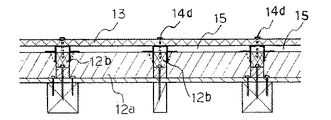
次に本発明の外張断熱施工方法の手順を説明する。図4、図6および図8に示す様に、本発明の外張断熱施工方法の手順としては、先ず一般的に普及している施工方法での軸組材及び間柱10の外面に構造用面材11を釘または螺子等14aで組み付け、次に前記構造用面材の外側に本胴縁材1の凹部2の底部を釘または螺子等14bにより構造用面材を介して軸組材に所定の位置に留め付ける。そして、図3、図5、図7および図9に示す様に、本胴縁材間に断熱材12aを敷設し、その後本冶具4を所定の位置に配設し断熱材の側面部と本胴縁材の側面部間に挿入される部位7aと断熱材に挿入される部位8aを挿入させるとともに断熱材の表面に接する部位5と本胴縁材の表面に接する部位6を着接させ、しかる後本胴縁材の表面に接する部位6に釘等の打ち込み用の穴9aに釘または螺子等14cを打ち付けるかまたは前記部位の一部をカギ状に切り欠いて折り曲げ釘等の代わりの機能を持たせる加工部9bを打ち付けて断熱材を保持固定する。そしてその後、図7および図10に示す様に、外装材13を本胴縁材の凸部3の頂部に釘または螺子等14dにより留め付けることにより主要なる施工は完了する。更に、断熱材を敷設する時に前記胴縁材の凹部にその形状に合わせた断熱材12bを付設すれば断熱性能を向上させる観点からも好ましい。また、断熱材と外装材間に設けられる空気層15を確保すれば結露防止の観点からも好ましい。なお、11の構造用面材においては室内側に枠材を設けている構造用パネルと称されるものも含み、12a、12bの断熱材の材質においては発泡樹脂系の板状断熱材が好ましいが繊維系断熱材のマット状のものも防湿層および防水透湿層の対応を行えば用いることが出来るので限定はされない。
【0015】
【発明の効果】
以上説明した様に、外張断熱工法において、次世代省エネルギー基準等により要求される厚みの厚い断熱材を施工する場合でも、本発明の本胴縁材と本冶具を用いる施工方法によれば、断熱材を二層三層と積層する必要もなく一層のみで簡便でし確実なる敷設を可能にするとともに、本胴縁材を留め付ける釘等が従来から在来木造の軸組工法およびツーバイフォー等の木造の枠組壁工法等で広く使用されている50〜75mm程度の長さのもので対応出来ることのみならず作業の効率化のために普及しつつあるエアー釘打ち機およびインパクトドライバー等も使用出来るので、外装材の留め付けが強固で確実にしかも容易に留め付けることが出来る。このように施工が簡便に確実に出来うるため、施工の合理化に貢献するのみならず、この施工方法の適用出来うる建物が、在来木造の軸組工法の建物のみならず、ツーバイフォー等の木造の枠組壁工法およびスチールハウスの鉄骨枠組壁工法等の建物と広範囲に可能であり、しかも適用部位も壁部のみならず屋根にも適用出来うるため、省エネおよび居住性の向上のための高品質な住宅を提供するために貢献し得る外張断熱工法の施工方法を提供することが出来る。
【図面の簡単な説明】
【図1】本胴縁材の形状例を示す模式図。
【図2】本冶具の形状例を示す模式図。
【図3】軸組材の外面に構造用面材を組み付け更に本胴縁材と本冶具および断熱材とを組み付けた状態例を示す模式図。
【図4】軸組材の外面に構造用面材を組み付け更に本胴縁材を組み付けた状態例を示す正面からの模式図。
【図5】図4の状態に加え本胴縁間に断熱材を敷設し本冶具を着設した状態例を示す正面からの模式図。
【図6】図4の状態例の縦断面の模式図。
【図7】図5の状態に加え外装材を組み付けた状態例を示す縦断面の模式図。
【図8】図4の状態例の横断面の模式図。
【図9】図5の状態例の縦断面の模式図。
【図10】図5の状態に加え外装材を組み付けた状態例を示す縦断面の模式図。
【符号の説明】
1 ;本胴縁材
2 ;本胴縁材の凹部
3 ;本胴縁材の凸部
4 ;本冶具
5 ;本冶具の断熱材の表面に接する部位
6 ;本冶具の本胴縁材の表面に接する部位
7a;本冶具の部位5と略直行する部位で断熱材の側面部と本胴縁材の側面部間に挿入される部位
7b;本冶具の部位5と本胴縁材の部位6との間の空気層に対応する部位
8a;本冶具の挿入部位7aの側面部から直立し断熱材に挿入される部位
8b;本冶具の部位5から直立して断熱材に挿入される部位
9a;本冶具の部位6に設けた釘または螺子等の打ち込み用の穴
9b;本冶具の部位6の一部をカギ状に切り欠いて折り曲げ釘等の代わりの機能を持たせる加工部
10 ;軸組材および間柱
11 ;構造用面材
12a;構造用面材の外面の本胴縁間に敷設される断熱材
12b;本胴縁材の凹部に付設される断熱材
13 ;外装材
14a;構造用面材を軸組材に留め付ける釘または螺子等
14b;本胴縁材を軸組材等に留め付ける釘または螺子等
14c;本冶具を本胴縁材に留め付ける釘または螺子等
14d;外装材を本胴縁材に留め付ける釘または螺子等
15 ;断熱材と外装材間に設けられた空気層[0001]
BACKGROUND OF THE INVENTION
TECHNICAL FIELD The present invention relates to a construction method for a building outer insulation method, and more particularly, to a construction method in the case where a structural surface material is assembled on the outer surface of a shaft assembly material and a heat insulation material is laid outside the surface material. . Examples of buildings to which this construction method can be applied include buildings of conventional wooden frame construction methods, wooden framework wall construction methods such as two-by-four, and steel framework steel framework wall construction methods.
[0002]
[Prior art]
In recent years, from the viewpoint of energy saving and residential comfort, it has become widespread to lay a heat insulating material on the floor, wall, ceiling, and roof base of a building. And as a heat insulation method for the wall portion of a detached building, an interaxial heat insulation method and an external heat insulation method are widely known. On the other hand, the next-generation energy-saving standards, which were implemented after several revisions of the energy-saving standards, generally stipulate that the thickness of the insulation is further thicker than the previous standards. There is a need for a heat insulating material that does not fit, and an outer heat insulating method that is less likely to cause dew condensation than an inter-shaft heat insulating method and that can reduce variations in room temperature. For this reason, it is expected that the outer insulation method will become widespread in the future.
[0003]
However, conventionally, the inter-shaft insulation method has been widely used, and the external insulation method has not been used much. As one of the factors, in the heat insulation between shafts, the exterior material can be fixed and fixed easily from the outer surface of the shaft material with a small trunk edge, but in the external insulation method, the heat insulation material jumps out of the shaft. When the thickness of the heat insulating material to be laid becomes thick, it is considered that the fixing of the exterior material becomes difficult. As an example, plate insulation such as resin foam insulation is often used as a conventional outer insulation method, but if the insulation is thin, the fastening strength of the exterior material is sacrificed. A method of laying down the heat insulating material by pressing it with a member that performs a trunk function has been tried in part. However, in this method, since the heat insulating material is not as strong as wood and has a risk of softening or melting at a high temperature, the strength transmission of the member performing the trunk edge function to fasten the exterior material is transmitted to the heat insulating material. However, the fastening strength of the exterior material to the shaft material depends on the bending strength in the state in which the heat insulating material such as the nail which fastens the member performing the trunk edge function to the shaft material has disappeared. In order to obtain the strength, it is necessary to use a thick and long nail or the like. For example, if a heat insulating material having a thickness of 50 mm is used, the thickness of the body edge material is about 20 mm and the total thickness becomes 70 mm. In consideration of the above, the nails that can be used are at least 90 mm, and if you try to use them, there is a risk that the trunk edge will crack and it will not function, and there will be a risk of dents in the insulation. Ri fastening it becomes difficult to the appropriate position, leaving the issue to the fastening fixing of the exterior material. For this reason, this method is not used much. On the other hand, in the next generation energy saving standards, the required thickness differs depending on the performance of the area and the heat insulating material, but the wall portion needs to have a thickness of about 100 mm, and such a thick heat insulating material is required. The use is rarely used because the problem of the fastening strength of the exterior material is too large to be realistic. For this reason, in some cases, heat insulating material with the required thickness of the heat insulating material divided into multiple layers is laminated, and square members corresponding to the trunk edge are assembled vertically and horizontally for each layer and the intersections are fastened with nails etc. Thus, a device for holding and fixing the exterior material is made. However, in this method, since the holding strength of the exterior material etc. depends on the fastening of the cross-shaped crossing of the square material corresponding to the trunk edge, the problem of strength still remains, and the heat insulating material is divided and attached Therefore, there is a problem in that it takes time for construction. Because of this, at present, as mentioned above, there are not enough proposals for appropriate fastening methods, etc., so it is difficult to perform appropriate thermal insulation by the external thermal insulation method. Therefore, the proposal of the construction method of the suitable outer-stretch heat insulation construction method including the fastening method of a heat insulating material is desired.
[0004]
[Problems to be solved by the invention]
The present invention has been made in view of the above-described conventional technology, and in the external thermal insulation method for buildings, it is easy to install without requiring the division of a thick insulating material required by the next-generation energy saving standards into multiple layers. It is another object of the present invention to provide a construction method for an external thermal insulation method in which the exterior material can be securely fastened securely and reliably.
[0005]
[Means for Solving the Problems]
In order to achieve the above-mentioned object, the external thermal insulation construction method according to the present invention is an external thermal insulation construction method for a building, in which a structural surface material is assembled on the outer surface of a shaft assembly material, and an insulation material is laid on the outside of the surface material. In the construction method, it has an uneven part formed at a predetermined pitch in the longitudinal direction, and the bottom part of the concave part is fastened to the shaft assembly material with a nail or screw or the like, and the exterior material is fastened to the top part of the convex part with a nail or screw or the like A member that can be used as a waist material, and a heat insulating material is laid between the material, and as a fastening method of the heat insulating material, a part made of a thin plate material and in contact with the surface of the heat insulating material, A portion that is in contact with the surface of the material, a portion that is inserted between the side surface portion of the heat insulating material and the side surface portion of the body edge material at a portion that is substantially perpendicular to the portion that is in contact with the surface of the heat insulating material, and the side surface portion of the heat insulating material Straight from the side of the part to be inserted between A portion to be inserted into the heat insulating material, or a portion to be inserted into the heat insulating material upright from a side portion of the portion in contact with the surface of the heat insulating material, and driving a nail or the like into a portion in contact with the surface of the body edge material A heat-insulating material fixing jig to which a function of replacing a bent nail or the like by cutting a part of the hole or a part of the part into a key shape is added is used.
[0006]
DETAILED DESCRIPTION OF THE INVENTION
Hereinafter, examples of the present invention will be described with reference to the drawings. However, the present invention is not limited to the following descriptions as long as the gist thereof is not exceeded. FIG. 1 is a schematic diagram showing an example of the shape of a trunk material having uneven portions formed at a predetermined pitch in the longitudinal direction used in the present invention, and FIG. 2 shows an example of the shape of a heat-insulating material fixing jig used in the present invention. Schematic diagram, FIG. 3 is a schematic diagram showing an example of a state in which a structural surface material is assembled to the outer surface of a shaft assembly material, and a body edge material, a jig for fixing a heat insulating material, and a heat insulating material are used in the present invention, and FIG. FIG. 5 is a schematic view from the front showing an example of a state in which a structural surface material is assembled to the outer surface of the shaft assembly material, and further a body edge material used in the present invention is assembled. FIG. 6 is a schematic view from the front showing an example of a state in which the jig for fixing a heat insulating material used in the present invention is attached, FIG. 6 is a schematic diagram of a longitudinal section of the state example of FIG. 4, and FIG. 7 is an exterior in addition to the state of FIG. FIG. 8 is a schematic cross-sectional view of the state example shown in FIG. 4, and FIG. Schematic diagram of a cross section of Tairei, FIG. 10 is a schematic diagram of a cross section showing a state example of assembling the outer package in addition to the state of FIG. In the description of each embodiment, “the trunk material having an uneven portion used in the present invention” is abbreviated as “main trunk material” as appropriate, and “the jig for fixing a heat insulating material used in the present invention” is appropriately referred to as “this Abbreviated as “Jig”.
[0007]
First, the
[0008]
Next, the
[0009]
The
[0010]
In the
[0011]
In the part 6, it is preferable that the width is about 20 to 40 mm and the protruding length is 15 to 30 mm, preferably about 1 mm smaller than the half of the width of the body edge material. Further, a
[0012]
In the
[0013]
In the
[0014]
Next, the procedure of the outer heat insulation construction method of the present invention will be described. As shown in FIGS. 4, 6, and 8, as a procedure of the external thermal insulation construction method of the present invention, first, a structural surface is provided on the outer surface of the frame member and the
[0015]
【The invention's effect】
As explained above, even in the case of constructing a thick heat insulating material required by the next-generation energy-saving standards, etc. in the outer insulation method, according to the construction method using the trunk edge material and the present jig of the present invention, There is no need to laminate two or three layers of heat insulating material, allowing simple and reliable laying with only one layer, and nails to fasten the main frame material have traditionally been used in traditional wooden frame construction methods, two-by-four, etc. Air nailing machines and impact drivers that are becoming popular for work efficiency are used as well as those with a length of about 50-75 mm that are widely used in wooden frame wall construction methods, etc. Since it can do, the exterior material can be firmly and securely fastened. In this way, the construction can be done easily and reliably, so that not only contributes to the rationalization of construction, but also the buildings to which this construction method can be applied are not only conventional wooden framed buildings but also wooden structures such as two-by-four It can be applied to a wide range of buildings such as steel framed wall construction method and steel house steel framed wall construction method, and it can be applied not only to the wall but also to the roof, so it is high quality for energy saving and improvement of habitability It is possible to provide a construction method of an outer insulation method that can contribute to providing a comfortable house.
[Brief description of the drawings]
FIG. 1 is a schematic diagram showing an example of the shape of the trunk edge material.
FIG. 2 is a schematic diagram showing a shape example of the jig.
FIG. 3 is a schematic view showing an example of a state in which a structural face material is assembled to the outer surface of a shaft assembly material, and further, a main body edge material, a main jig and a heat insulating material are assembled.
FIG. 4 is a schematic diagram from the front showing an example of a state in which a structural face material is assembled to the outer surface of the shaft assembly material, and further, this barrel edge material is assembled.
FIG. 5 is a schematic front view showing an example of a state in which a heat insulating material is laid between the main body edges in addition to the state of FIG.
6 is a schematic diagram of a longitudinal section of the state example of FIG. 4;
7 is a schematic longitudinal sectional view showing a state example in which an exterior material is assembled in addition to the state of FIG.
8 is a schematic cross-sectional view of the state example of FIG.
9 is a schematic diagram of a longitudinal section of the state example of FIG.
10 is a schematic longitudinal sectional view showing a state example in which an exterior material is assembled in addition to the state of FIG.
[Explanation of symbols]
DESCRIPTION OF SYMBOLS 1; Main trunk edge material 2; Concave part 3 of main trunk edge material; Convex part 4 of main trunk edge material; This jig 5; The site | part 6 which contact | connects the surface of the heat insulating material of this jig; A part 7a in contact with the part 5; a part 7b inserted between the side part of the heat insulating material and the side part of the body edge material at a part substantially perpendicular to the part 5 of the jig; the part 5 of the jig and the part 6 of the body edge material Part 8a corresponding to the air layer between them; part 8b standing upright from the side of the insertion part 7a of the jig and inserted into the heat insulating material; part 9a standing up from the part 5 of the jig and inserted into the heat insulating material A hole 9b for driving a nail or a screw or the like provided in the part 6 of the jig; a processing part 10 that cuts out a part of the part 6 of the jig in a key shape and has a function instead of a bent nail or the like; Assembled material and studs 11; structural face material 12a; heat insulating material 12b laid between the main body edges on the outer surface of the structural face material; A heat insulating material 13 attached to the part; an exterior material 14a; a nail or a screw 14b for fastening the structural surface material to the shaft assembly; a nail or a screw 14c for fastening the main frame material to the shaft assembly or the like; 14d; nail or screw etc. for fastening the outer shell material to the main body edge material 15; nail or screw etc. 15 for fixing the outer material to the main body edge material; air layer provided between the heat insulating material and the outer material
Claims (2)
Priority Applications (1)
| Application Number | Priority Date | Filing Date | Title |
|---|---|---|---|
| JP2000241840A JP4414074B2 (en) | 2000-07-06 | 2000-07-06 | Outer insulation construction method |
Applications Claiming Priority (1)
| Application Number | Priority Date | Filing Date | Title |
|---|---|---|---|
| JP2000241840A JP4414074B2 (en) | 2000-07-06 | 2000-07-06 | Outer insulation construction method |
Publications (2)
| Publication Number | Publication Date |
|---|---|
| JP2002021206A JP2002021206A (en) | 2002-01-23 |
| JP4414074B2 true JP4414074B2 (en) | 2010-02-10 |
Family
ID=18732966
Family Applications (1)
| Application Number | Title | Priority Date | Filing Date |
|---|---|---|---|
| JP2000241840A Expired - Fee Related JP4414074B2 (en) | 2000-07-06 | 2000-07-06 | Outer insulation construction method |
Country Status (1)
| Country | Link |
|---|---|
| JP (1) | JP4414074B2 (en) |
-
2000
- 2000-07-06 JP JP2000241840A patent/JP4414074B2/en not_active Expired - Fee Related
Also Published As
| Publication number | Publication date |
|---|---|
| JP2002021206A (en) | 2002-01-23 |
Similar Documents
| Publication | Publication Date | Title |
|---|---|---|
| US20070227095A1 (en) | Separated Member Wood Framing | |
| WO2009089768A1 (en) | Combined house without nail | |
| JP4414074B2 (en) | Outer insulation construction method | |
| JP5169367B2 (en) | Insulated ceiling | |
| JP5620213B2 (en) | Thermal insulation structure of building and its construction method | |
| JPH0330482Y2 (en) | ||
| JP3018279B2 (en) | Houses using panels for building wooden houses | |
| JP2003262002A (en) | Connecting structure of core material and external facing material and composite material | |
| JP2002227321A (en) | Wall foundation spacer and assembly method thereof | |
| JP2686585B2 (en) | Heat dissipation panel Fireproof roof structure | |
| JP2003301539A (en) | External heat insulation construction method and heat insulation material joining member | |
| JP2003232094A (en) | Furring-strip fitting and outside heat-insulating structure using it | |
| JPS6039377Y2 (en) | wall panels | |
| JPH094126A (en) | Architectural panel | |
| JPH1171834A (en) | Member for building structure, and method for realizing airtight building | |
| JP5204541B2 (en) | Insulation wall | |
| JP3790156B2 (en) | Building | |
| JP3676444B2 (en) | Building wall construction method and panel assembly | |
| JP2001003479A (en) | Building panel | |
| JP5745983B2 (en) | Outside heat insulation structure | |
| JP2002340352A (en) | Manufacturing method for floor heating panel corresponding to finishing specified floor member, and establishment of floor heating system without design calculation | |
| JPH09184208A (en) | Frame structure of building | |
| JP4207214B2 (en) | Construction methods for interior and exterior base materials and concrete structures | |
| KR200370361Y1 (en) | Roof composite sandwich panel | |
| JPH11310971A (en) | Architectural heat insulation panel and production thereof |
Legal Events
| Date | Code | Title | Description |
|---|---|---|---|
| A621 | Written request for application examination |
Free format text: JAPANESE INTERMEDIATE CODE: A621 Effective date: 20070619 |
|
| A977 | Report on retrieval |
Free format text: JAPANESE INTERMEDIATE CODE: A971007 Effective date: 20090910 |
|
| TRDD | Decision of grant or rejection written | ||
| A01 | Written decision to grant a patent or to grant a registration (utility model) |
Free format text: JAPANESE INTERMEDIATE CODE: A01 Effective date: 20091013 |
|
| A01 | Written decision to grant a patent or to grant a registration (utility model) |
Free format text: JAPANESE INTERMEDIATE CODE: A01 |
|
| FPAY | Renewal fee payment (event date is renewal date of database) |
Free format text: PAYMENT UNTIL: 20121127 |
|
| R150 | Certificate of patent or registration of utility model |
Free format text: JAPANESE INTERMEDIATE CODE: R150 |
|
| FPAY | Renewal fee payment (event date is renewal date of database) |
Free format text: PAYMENT UNTIL: 20121127 Year of fee payment: 3 |
|
| FPAY | Renewal fee payment (event date is renewal date of database) |
Free format text: PAYMENT UNTIL: 20121127 Year of fee payment: 3 |
|
| FPAY | Renewal fee payment (event date is renewal date of database) |
Free format text: PAYMENT UNTIL: 20131127 Year of fee payment: 4 |
|
| R250 | Receipt of annual fees |
Free format text: JAPANESE INTERMEDIATE CODE: R250 |
|
| LAPS | Cancellation because of no payment of annual fees |