JP4413402B2 - Exterior wall panel and exterior wall structure - Google Patents
Exterior wall panel and exterior wall structure Download PDFInfo
- Publication number
- JP4413402B2 JP4413402B2 JP2000282738A JP2000282738A JP4413402B2 JP 4413402 B2 JP4413402 B2 JP 4413402B2 JP 2000282738 A JP2000282738 A JP 2000282738A JP 2000282738 A JP2000282738 A JP 2000282738A JP 4413402 B2 JP4413402 B2 JP 4413402B2
- Authority
- JP
- Japan
- Prior art keywords
- wall
- heat insulating
- panel
- insulating material
- wall panel
- Prior art date
- Legal status (The legal status is an assumption and is not a legal conclusion. Google has not performed a legal analysis and makes no representation as to the accuracy of the status listed.)
- Expired - Fee Related
Links
- 239000011810 insulating material Substances 0.000 claims description 57
- 239000000463 material Substances 0.000 claims description 50
- 238000009413 insulation Methods 0.000 claims description 8
- 239000012784 inorganic fiber Substances 0.000 claims description 2
- 239000002184 metal Substances 0.000 claims description 2
- 229910000831 Steel Inorganic materials 0.000 description 5
- 239000010959 steel Substances 0.000 description 5
- 239000000470 constituent Substances 0.000 description 3
- 239000011490 mineral wool Substances 0.000 description 3
- 238000010276 construction Methods 0.000 description 2
- 238000000034 method Methods 0.000 description 2
- 238000005507 spraying Methods 0.000 description 2
- JOYRKODLDBILNP-UHFFFAOYSA-N Ethyl urethane Chemical compound CCOC(N)=O JOYRKODLDBILNP-UHFFFAOYSA-N 0.000 description 1
- 239000000919 ceramic Substances 0.000 description 1
- 230000005494 condensation Effects 0.000 description 1
- 238000009833 condensation Methods 0.000 description 1
- 238000001816 cooling Methods 0.000 description 1
- 238000004079 fireproofing Methods 0.000 description 1
- 238000010438 heat treatment Methods 0.000 description 1
- 238000012986 modification Methods 0.000 description 1
- 230000004048 modification Effects 0.000 description 1
- 230000002265 prevention Effects 0.000 description 1
- XLYOFNOQVPJJNP-UHFFFAOYSA-N water Substances O XLYOFNOQVPJJNP-UHFFFAOYSA-N 0.000 description 1
Images
Landscapes
- Building Environments (AREA)
- Load-Bearing And Curtain Walls (AREA)
Description
【0001】
【発明の属する技術分野】
本発明は、外壁パネル及び外壁構造に関する。
【0002】
【従来の技術】
例えばGRCなどのコンクリート系外壁材の背面側がパネルフレームが取り付けられた外壁パネルでは、断熱効果を出すために、この外壁パネルを建物躯体に取り付けた後、外壁パネルの外壁材の背面側にロックウールを吹き付けたり、ウレタンボードを貼り付けることが行われていた。
【0003】
【発明が解決しようとする課題】
しかしながら、外壁パネルを建物躯体に取り付けた後に断熱材の吹付けや貼付けを行うのでは、現場での施工に手間を要するという問題があった。
【0004】
また、外壁パネルは、外壁材とパネルフレームとが締結されると共に、パネルフレームと建物躯体、例えば鉄骨梁とが連結されるため、ヒートブリッジを生じて、充分な断熱性能を得られない場合があるという問題もあった。
【0005】
本発明は、上記のような従来の問題点に鑑み、現場での施工を省力化することができ、しかも、高い断熱性能を発揮することができる外壁パネル及び外壁構造を提供することを課題とする。
【0006】
【課題を解決するための手段】
上記の課題は、パネルフレームが外断熱材を介して外壁材の背面側に取り付けられていることを特徴とする外壁パネルによって解決される。
【0007】
この外壁パネルでは、パネルフレームが外断熱材を介して外壁材に取り付けられているので、外壁材とパネルフレームとの間の熱の行き来が防止ないしは抑制され、そのため、ヒートブリッジを生じにくくなり、高い断熱効果を得ることができる。
【0008】
もちろん、この外壁パネルによれば、建物躯体をその外側から断熱材で覆う外断熱構造とすることができるので、内部結露を生じにくく、暖冷房を停止しても急激な温度変化を生じず、また、躯体を守ってその耐久性を高めることができる。
【0009】
しかも、断熱材は、外壁パネルのなかに予め組み込まれているので、この外壁パネルを現場で取り付ければ、同時に断熱材も取り付けられることになり、現場での施工を省力化することができる。
【0010】
パネルフレームが金属製フレームからなる場合は、外壁材とパネルフレームとの間の熱の行き来を外断熱材で効果的に防止ないしは抑制することができ、また、外断熱材がマット状の無機繊維質断熱材からなる場合は、防火性能をも高めることができると共に、外断熱材を外壁材とパネルフレームとの間にしっかりと挟み込むことができ、更に、パネル一般部についての現場での耐火処理を省略することが可能となる。
【0011】
また、上記の外壁パネルが複数隣り合わせ状態に並べられて形成された外壁構造にして、
隣り合ういずれか一方又は両方の外壁パネルの外断熱材が外壁材の背面側の縁部よりも外方に突出し、この突出によって、隣り合う外壁材間の目地が外壁材の背面側から塞がれている外壁構造では、
断熱材を予め外壁パネルの構成部材とした構成でありながら、目地を通じた屋内外の熱の行き来をこの断熱材で防ぐことができ、より一層高い断熱効果を得ることができる。しかも、施工は、外壁パネルを現場に取り付けるだけでよい。
【0012】
更に、隣り合う外壁パネルの外断熱材同士が離間することなく連続状に備えられている場合は、同じく断熱材を予め外壁パネルの構成部材とした構成でありながら、高い断熱効果を得ることができる。特に、外断熱材が繊維質断熱材からなる場合は、隣り合う外壁パネルの外断熱材同士をうまい具合に施工容易に突き合わせなどによる連続状態にすることができる。
【0013】
【発明の実施の形態】
次に、本発明の実施形態を図面に基づいて説明する。
【0014】
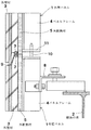
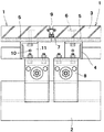
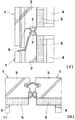
図1及び図4に示す第1実施形態の外壁構造において、1は外壁パネル、2は建物躯体の梁である。外壁パネル1は、外壁材3と、パネルフレーム4と、外断熱材5とを主要構成部材として備えたものである。躯体の梁2は、鉄骨梁からなり、例えば、上下のフランジとそれらをつなぐウェブとを備えたH形鋼からなる。
【0015】
外壁材3は、GRCなどのコンクリート系の面状外壁材からなっていて、その厚さ寸法は、例えば60mmである。この外壁材3には、アンカー6が埋め込まれていて、このアンカー6を用いてパネルフレーム4を接合することができるようになっている。パネルフレーム4は、鋼製のもので、横断面L字状の山形鋼が縦向きで用いられている。
【0016】
外断熱材5は、例えばロックウールマットなどのマット状の無機繊維質断熱材からなっている。その厚さ寸法は、例えば20mmである。また、図4に示すように、上下方向の長さ寸法は、この外断熱材5を外壁材3の背面部に沿わせた状態で、その上縁部が外壁材3の背面側の上縁部よりも上方に突出し、かつ、その下縁部が外壁材3の背面側の下縁部よりも下方に突出するような寸法に設計されている。また、左右方向の長さ寸法についても、この外断熱材5を外壁材3の背面部に沿わせた状態で、その両側縁部が外壁材3の背面側の左右両側縁部よりも外方に突出するような寸法に設計されている。実施形態の場合は、上下左右方向に隣り合って取り付けられる外壁パネル間の目地幅の半分ないしはそれよりも幾分大きな寸法だけ突出するように設計されている。
【0017】
外壁パネル1は、上記の外壁材3の背面側に外断熱材5を配置すると共に、この外断熱材5の更に背面側にパネルフレーム4を配置し、そして、外壁材3に埋め込まれているアンカー6を利用し、ボルトやナットなどのネジ締結部材でパネルフレーム4の背面側から締付けを行うことで、これら三者を一体化して製作されている。外断熱材5は、外壁材3とパネルフレーム4との間に挟み込まれて備えられている。
【0018】
なお、外壁パネル1には、その外壁材3の周面の背面側に寄った部分に、予め、止水材7が取り付けられている。この止水材7は、弾力性を有するゴム状材などからなり、隣り合って取り付けられる外壁パネルの止水材と弾力的に当接させることで、目地9を止水すると共に、目地9内を屋外と同じ等圧空間にするものである。
【0019】
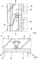
上記の外壁パネル1は、そのパネルフレーム4をファスナー8を用いて建物躯体の梁2にファスナー8でボルト接合することによって躯体に取り付けられる。こうして、複数の外壁パネルを、左右方向及び/又は上下方向に同じように並べて取り付けていくことによって外壁が形成されていく。同時に、上記の止水材7,7同士が弾力的に当接し合って目地9が止水状態になり、また、隣り合う外壁パネル1,1の外断熱材5,5の縁部同士も突き合わせ当接状態となって、目地9が外壁材3,3の背面側から塞がれ、隣り合う外壁パネル1,1の外断熱材5,5同士が離間することなく連続状になる。
【0020】
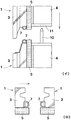
なお、外壁パネル1のパネルフレーム4の上端にはダボ10が上方に突出して備えられると共に、この外壁パネル1の上方に隣接して取り付けられる外壁パネル1のパネルフレーム4の下端には、孔付きのプレート11が備えられ、上側の外壁パネルをダボ10がプレート11の孔内に入るようにセットすることで、上側の外壁パネル1を下側の外壁パネルと面一となるように容易に位置決めすることができるようになっている。これにより、上下の外断熱材5,5同士もうまい具合に連続状態になる。
【0021】
上記の外壁パネル1及び外壁構造では、パネルフレーム4が外断熱材5を介して外壁材3に取り付けられているので、外壁材3とパネルフレーム4との間の熱の行き来が防止ないしは抑制され、そのため、ヒートブリッジを生じにくくなり、高い断熱効果を得られる。
【0022】
しかも、外断熱材5は、外壁パネル1のなかに予め組み込まれているので、この外壁パネル1を躯体に取り付ければ、同時に外断熱材5も取り付けられ、そのため、現場での施工を省力化することができる。
【0023】
また、外断熱材5は、ロックウールマットなどのマット状の無機繊維質断熱材からなるので、防火性能をも高めることができると共に、外断熱材5を外壁材3とパネルフレーム4との間にしっかりと挟み込むことができ、更に、パネル一般部についての現場での耐火処理を省略することが可能となる。
【0024】
加えて、この外壁パネル1…を用いて形成した外壁構造では、外壁パネル1…を取り付けていくことで、各外壁パネル1の外断熱材5の縁部同士が当接し合った状態となり、上下及び/又は左右に隣り合う外壁パネル1,1の外壁材3,3間の目地9の部分がその背面側から塞がれるので、外断熱材5を予め外壁パネル1の構成部材としたものでありながら、目地9を通じた屋内外の熱の行き来をこの外断熱材5で防ぐことができ、より一層高い断熱効果を得ることができる。しかも、施工は、外壁パネル1…を現場に取り付けていくだけでよい。更に、止水材7,7で目地9は止水されているので、外断熱材5,5を雨などで濡らすこともない。
【0025】
更に、隣り合う外壁パネル1,1の外断熱材5,5同士が、離間することなく当接して連続状に備えられているので、外壁の面内において断熱のとぎれるところがなく、外断熱材5を予め外壁パネル1の構成部材とした構成でありながら、高い断熱効果を得ることができる。
【0026】
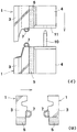
図5及び図6に示す第2実施形態では、外壁パネル1において、その外断熱材5の縁部が外壁材3の背面側の縁部から突出しない構成にされている。本実施形態では、外断熱材5が、隣り合う外壁材3間の目地をその背後から塞ぐことはないけれども、基本的効果については、上記の第1実施形態のものと変わることはない。その他の構成は、第1実施形態と同様である。なお、第2実施形態において、縦目地の側においてのみ第1実施形態の場合と同様に外断熱材を突出させるようにしてもよいし、横目地の側においてのみ第1実施形態の場合と同様に外断熱材を突出させるようにしてもよい。
【0027】
以上に、本発明の実施形態を示したが、本発明はこれに限られるものではなく、発明思想を逸脱しない範囲で各種の変更が可能である。例えば、上記の実施形態では、隣り合う外壁パネル1,1の外断熱材5,5同士が、目地9の幅方向中間部分で突き合わされて目地9をその背面側から塞ぐようになっているが、隣り合う一方の外壁パネルの外断熱材のみを突出させ、隣り合うもう一方の外壁パネルの外断熱材は突出させず、それにより、前記一方の外壁材の外断熱材のみで、目地をその背後から塞ぐ構成としてもよい。即ち、隣り合う外壁パネルの外断熱材同士を離間させることなく連続状に突き合わせる位置は、目地部分でなくてもよく、目地部分を避けて外壁材の背面側の位置に設定するようにしてもよい。このように外断熱材同士の突き合わせ部分を目地から避けるようにすることで、目地部分の断熱をより一層確実なものにすることができる。
【0028】
また、上記の実施形態では、外壁パネル1の外壁材3として、コンクリート系のものを用いた場合を示しており、本発明は、外壁材3がコンクリート系である場合には特に効果あるものであるが、必ずしもこれに限られるものではなく、その他、例えば窯業系などの各種の外壁材を用いた外壁パネルに適用されてもよい。また、外壁パネルは、一つの外壁材を用いて構成されたものであってもよいし、あるいは、複数の外壁材を上下方向及び/又は左右方向に隣り合わせ状態に組み合わせ、パネルフレームなどでこれら外壁材を一体化して外壁パネルとしたものであってもよい。また、パネルフレーム4は、各種横断面形状を有するものであってよいし、外断熱材5の背面側での取付け位置や取り付け方法も各種態様のものであってよい。
【0029】
【発明の効果】
本発明は、以上のとおりのものであるから、現場での施工を省力化することができ、しかも、高い断熱性能を発揮することができる。
【図面の簡単な説明】
【図1】第1実施形態の外壁構造の垂直断面図である。
【図2】同水平断面図である。
【図3】図(イ)は上下の外壁パネル間の構造を示す垂直断面図、図(ロ)は左右の外壁パネル間の構造を示す水平断面図である。
【図4】図(イ)は上下の外壁パネルを分離状態にして示す垂直断面図、図(ロ)は左右の外壁パネルを分離状態にして示す水平断面図である。
【図5】第2実施形態の外壁構造を示すもので、図(イ)は上下の外壁パネル間の構造を示す垂直断面図、図(ロ)は左右の外壁パネル間の構造を示す水平断面図である。
【図6】図(イ)は上下の外壁パネルを分離状態にして示す垂直断面図、図(ロ)は左右の外壁パネルを分離状態にして示す水平断面図である。
【符号の説明】
1…外壁パネル
2…躯体の梁
3…外壁材
4…パネルフレーム
5…外断熱材[0001]
BACKGROUND OF THE INVENTION
The present invention relates to an outer wall panel and an outer wall structure.
[0002]
[Prior art]
For example, in the case of an outer wall panel with a panel frame attached to the back side of a concrete-type outer wall material such as GRC, after attaching the outer wall panel to a building frame, in order to provide a heat insulation effect, rock wool Spraying or pasting urethane boards.
[0003]
[Problems to be solved by the invention]
However, spraying and pasting the heat insulating material after attaching the outer wall panel to the building frame has a problem that it takes time and labor for the construction at the site.
[0004]
In addition, since the outer wall panel is fastened to the outer wall material and the panel frame and the panel frame and the building frame, for example, a steel beam, are connected to each other, a heat bridge is generated and sufficient heat insulation performance may not be obtained. There was also a problem.
[0005]
In view of the above-described conventional problems, the present invention has an object to provide an outer wall panel and an outer wall structure that can save labor in the field and can exhibit high heat insulation performance. To do.
[0006]
[Means for Solving the Problems]
Said subject is solved by the outer wall panel characterized by the panel frame being attached to the back side of the outer wall material via the outer heat insulating material.
[0007]
In this outer wall panel, since the panel frame is attached to the outer wall material via the outer heat insulating material, the passage of heat between the outer wall material and the panel frame is prevented or suppressed, so that it is difficult to generate a heat bridge, A high heat insulating effect can be obtained.
[0008]
Of course, according to this outer wall panel, since it can be an outer heat insulating structure that covers the building frame with a heat insulating material from the outside, it is difficult to cause internal condensation, and a sudden temperature change does not occur even if heating and cooling is stopped. Moreover, the durability can be enhanced by protecting the housing.
[0009]
In addition, since the heat insulating material is preliminarily incorporated in the outer wall panel, if the outer wall panel is attached at the site, the heat insulating material can be attached at the same time, and the construction at the site can be saved.
[0010]
When the panel frame is made of a metal frame, the heat transfer between the outer wall material and the panel frame can be effectively prevented or suppressed by the outer heat insulating material, and the outer heat insulating material is a mat-like inorganic fiber. When it is made of high-quality heat insulating material, it can enhance fire prevention performance, and the outer heat insulating material can be firmly sandwiched between the outer wall material and the panel frame. Can be omitted.
[0011]
Moreover, in the outer wall structure formed by arranging a plurality of the above outer wall panels side by side,
The outer heat insulating material of one or both of the adjacent outer wall panels protrudes outward from the edge on the back side of the outer wall material, and this protrusion blocks the joint between the adjacent outer wall materials from the back side of the outer wall material. In the outer wall structure
Even though the heat insulating material is configured as a constituent member of the outer wall panel in advance, it is possible to prevent the indoor and outdoor heat from passing through the joint with this heat insulating material, and a higher heat insulating effect can be obtained. Moreover, it is only necessary to install the outer wall panel on the site.
[0012]
Furthermore, in the case where the outer heat insulating materials of adjacent outer wall panels are provided continuously without being separated from each other, a high heat insulating effect can be obtained even though the heat insulating material is configured as a constituent member of the outer wall panel in advance. it can. In particular, when the outer heat insulating material is made of a fibrous heat insulating material, the outer heat insulating materials of the adjacent outer wall panels can be made into a continuous state by easy matching and the like.
[0013]
DETAILED DESCRIPTION OF THE INVENTION
Next, embodiments of the present invention will be described with reference to the drawings.
[0014]
In the outer wall structure of the first embodiment shown in FIGS. 1 and 4, 1 is an outer wall panel, and 2 is a beam of a building frame. The
[0015]
The
[0016]
The outer
[0017]
In the
[0018]
In addition, the
[0019]
The above
[0020]
A
[0021]
In the
[0022]
Moreover, since the outer
[0023]
Further, since the outer
[0024]
In addition, in the outer wall structure formed by using the
[0025]
Further, since the outer
[0026]
In the second embodiment shown in FIGS. 5 and 6, the
[0027]
Although the embodiment of the present invention has been described above, the present invention is not limited to this, and various modifications can be made without departing from the spirit of the invention. For example, in the above-described embodiment, the outer
[0028]
Moreover, in said embodiment, the case where a concrete type thing is used as the
[0029]
【The invention's effect】
Since the present invention is as described above, it is possible to save labor on site and to exhibit high heat insulation performance.
[Brief description of the drawings]
FIG. 1 is a vertical sectional view of an outer wall structure according to a first embodiment.
FIG. 2 is a horizontal sectional view of the same.
FIG. 3A is a vertical sectional view showing a structure between upper and lower outer wall panels, and FIG. 3B is a horizontal sectional view showing a structure between left and right outer wall panels.
FIG. 4A is a vertical sectional view showing the upper and lower outer wall panels in a separated state, and FIG. 4B is a horizontal sectional view showing the left and right outer wall panels in a separated state.
5A and 5B show an outer wall structure according to a second embodiment. FIG. 5A is a vertical sectional view showing a structure between upper and lower outer wall panels, and FIG. 5B is a horizontal section showing a structure between left and right outer wall panels. FIG.
FIG. 6A is a vertical sectional view showing the upper and lower outer wall panels in a separated state, and FIG. 6B is a horizontal sectional view showing the left and right outer wall panels in a separated state.
[Explanation of symbols]
DESCRIPTION OF
Claims (3)
隣り合ういずれか一方又は両方の外壁パネルの外断熱材が外壁材の背面側の縁部よりも外方に突出し、この突出によって、隣り合う外壁材間の目地が外壁材の背面側から塞がれていることを特徴とする外壁構造。In the outer wall structure formed by arranging a plurality of the outer wall panels according to claim 1 side by side,
The outer heat insulating material of one or both of the adjacent outer wall panels protrudes outward from the edge on the back side of the outer wall material, and this protrusion blocks the joint between the adjacent outer wall materials from the back side of the outer wall material. The outer wall structure is characterized by
Priority Applications (1)
| Application Number | Priority Date | Filing Date | Title |
|---|---|---|---|
| JP2000282738A JP4413402B2 (en) | 2000-09-18 | 2000-09-18 | Exterior wall panel and exterior wall structure |
Applications Claiming Priority (1)
| Application Number | Priority Date | Filing Date | Title |
|---|---|---|---|
| JP2000282738A JP4413402B2 (en) | 2000-09-18 | 2000-09-18 | Exterior wall panel and exterior wall structure |
Publications (2)
| Publication Number | Publication Date |
|---|---|
| JP2002088955A JP2002088955A (en) | 2002-03-27 |
| JP4413402B2 true JP4413402B2 (en) | 2010-02-10 |
Family
ID=18767192
Family Applications (1)
| Application Number | Title | Priority Date | Filing Date |
|---|---|---|---|
| JP2000282738A Expired - Fee Related JP4413402B2 (en) | 2000-09-18 | 2000-09-18 | Exterior wall panel and exterior wall structure |
Country Status (1)
| Country | Link |
|---|---|
| JP (1) | JP4413402B2 (en) |
Families Citing this family (3)
| Publication number | Priority date | Publication date | Assignee | Title |
|---|---|---|---|---|
| CN105952043B (en) * | 2016-06-08 | 2018-11-20 | 金刚幕墙集团有限公司 | A kind of modular insulated fire curtain wall system |
| CN112252550B (en) * | 2020-10-14 | 2021-08-31 | 贵阳迪乐普科技有限公司 | A kind of LED module for building exterior wall installation |
| CN115126095A (en) * | 2022-05-11 | 2022-09-30 | 同创金泰建筑技术(北京)有限公司 | Connecting device suitable for ultra-low energy consumption curtain |
-
2000
- 2000-09-18 JP JP2000282738A patent/JP4413402B2/en not_active Expired - Fee Related
Also Published As
| Publication number | Publication date |
|---|---|
| JP2002088955A (en) | 2002-03-27 |
Similar Documents
| Publication | Publication Date | Title |
|---|---|---|
| JP5077664B2 (en) | RC building method with no external insulation and no adjacent space | |
| JP2018035662A (en) | Wall body heat insulation system assembly with aseismatic panel for absorbing vibration | |
| JP6257021B2 (en) | Insulation panel connection structure | |
| JP4413402B2 (en) | Exterior wall panel and exterior wall structure | |
| KR101141158B1 (en) | An insulation system of an outer wall and an installation method using it | |
| KR101765673B1 (en) | An assembly stud for sound insulation | |
| JP6511252B2 (en) | Exterior wall panel joint fireproof structure | |
| JP2925984B2 (en) | Architectural exterior panel structure | |
| KR20070005334A (en) | Prefabricated wall panel and building wall using the same | |
| RU2108431C1 (en) | Wall panel | |
| KR101057766B1 (en) | Building panel | |
| JP3800811B2 (en) | Building floor structure and construction method | |
| JP2954619B2 (en) | Building panel | |
| JPH0347358A (en) | Structure of joint for panel | |
| CN113494140B (en) | Thermal insulation building and construction process thereof | |
| JP2025147788A (en) | Fire-resistant structure and reinforcement for joints of exterior wall panels | |
| JP2826343B2 (en) | Wall joint structure | |
| JP2025031096A (en) | Sandwich panel mask system and sandwich panel mask construction method | |
| JPH0762381B2 (en) | Outer wall structure | |
| JPH1144079A (en) | Improved construction of alc external wall | |
| JP2025150206A (en) | Fire-resistant structure and fire-resistant equipment for vertical joints | |
| JP4044691B2 (en) | Fire spread prevention structure and fire spread prevention material | |
| JP2025014951A (en) | Sandwich panel and exterior wall structure using the same | |
| SU1000525A1 (en) | Versions of butt joint of outer wall panels | |
| JP2846645B2 (en) | Sandwich panel |
Legal Events
| Date | Code | Title | Description |
|---|---|---|---|
| A621 | Written request for application examination |
Free format text: JAPANESE INTERMEDIATE CODE: A621 Effective date: 20070914 |
|
| A977 | Report on retrieval |
Free format text: JAPANESE INTERMEDIATE CODE: A971007 Effective date: 20090806 |
|
| A131 | Notification of reasons for refusal |
Free format text: JAPANESE INTERMEDIATE CODE: A131 Effective date: 20090818 |
|
| A521 | Written amendment |
Free format text: JAPANESE INTERMEDIATE CODE: A523 Effective date: 20091016 |
|
| TRDD | Decision of grant or rejection written | ||
| A01 | Written decision to grant a patent or to grant a registration (utility model) |
Free format text: JAPANESE INTERMEDIATE CODE: A01 Effective date: 20091117 |
|
| A01 | Written decision to grant a patent or to grant a registration (utility model) |
Free format text: JAPANESE INTERMEDIATE CODE: A01 |
|
| A61 | First payment of annual fees (during grant procedure) |
Free format text: JAPANESE INTERMEDIATE CODE: A61 Effective date: 20091118 |
|
| FPAY | Renewal fee payment (event date is renewal date of database) |
Free format text: PAYMENT UNTIL: 20121127 Year of fee payment: 3 |
|
| R150 | Certificate of patent or registration of utility model |
Free format text: JAPANESE INTERMEDIATE CODE: R150 |
|
| FPAY | Renewal fee payment (event date is renewal date of database) |
Free format text: PAYMENT UNTIL: 20121127 Year of fee payment: 3 |
|
| FPAY | Renewal fee payment (event date is renewal date of database) |
Free format text: PAYMENT UNTIL: 20151127 Year of fee payment: 6 |
|
| R250 | Receipt of annual fees |
Free format text: JAPANESE INTERMEDIATE CODE: R250 |
|
| LAPS | Cancellation because of no payment of annual fees |