JP4412890B2 - Throwaway end mill - Google Patents
Throwaway end mill Download PDFInfo
- Publication number
- JP4412890B2 JP4412890B2 JP2002284422A JP2002284422A JP4412890B2 JP 4412890 B2 JP4412890 B2 JP 4412890B2 JP 2002284422 A JP2002284422 A JP 2002284422A JP 2002284422 A JP2002284422 A JP 2002284422A JP 4412890 B2 JP4412890 B2 JP 4412890B2
- Authority
- JP
- Japan
- Prior art keywords
- tip
- edge
- outer peripheral
- cutting edge
- blade
- Prior art date
- Legal status (The legal status is an assumption and is not a legal conclusion. Google has not performed a legal analysis and makes no representation as to the accuracy of the status listed.)
- Expired - Fee Related
Links
Images


Description
【0001】
【発明の属する技術分野】
本発明は、回転工具として用いられるスローアウェイエンドミル、特に3次元切削が可能な底刃付きエンドミルと、それに装着されるスローアウェイチップに関する。
【0002】
【従来の技術】
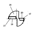
3次元切削が可能なスローアウェイエンドミルにおいては、その加工の形態として、切刃の配置が外周刃のみでエンドミル軸心まで切刃を備えていない通常のエンドミルで加工可能である肩加工や溝加工に加えて、エンドミル軸心まで切刃があることにより、被削材に対して斜めに沈み込んでいく様な加工や、ドリル加工のように軸芯方向へ鉛直に沈み込む加工が可能である。この様な3次元エンドミルには、従来、略平行四辺形のスローアウェイチップが用いられている。図4乃至図6は従来例としての3次元エンドミルを示す。図4は従来例のスローアウェイチップ17を示すものであり、図4(a)はその平面図、(b)は短辺側側面図、(c)は長辺側側面図を示す。図5は従来例のスローアウェイチップ17をエンドミル本体18に装着した状態のエンドミル側面図、図6は図5の底面図である。図5に示すように、第1のチップはその長辺切刃19を外周刃として、短辺切刃20を底刃としてエンドミル本体18に取り付けられ、第2のチップは長辺切刃19を底刃として、短辺切刃20を外周刃としてエンドミル本体18に取り付けらている。(例えば、特許文献1参照。)
従来のチップは、第1および第2のチップの外周刃が全長にわたって直線状で、且つ先端および後端ならびに第2のチップ外周刃の先端および後端の加工径が同一または略同一となるチップ配置であった。
【0003】
【特許文献1】
特開平8−323527号公報
【0004】
【発明が解決しようとする課題】
ところが、前記従来のスローアウェイエンドミルは、エンドミル加工を行なう際、高送り領域で加工を行なうと、異常振動を起こし易く、加工効率を上げることが難しいという問題があった。
【0005】
【課題を解決するための手段】
上記課題を解決するため、請求項1記載のスローアウェイエンドミルは、略円柱状の工具本体の先端部に、多角形板状をなすチップ本体の側面と上面との交叉稜に短辺切刃と長辺切刃を設けた第1及び第2のチップを備えるとともに、前記第1のチップは前記長辺切刃を外周刃として、前記短辺切刃を底刃として工具本体に取り付けられ、前記第2のチップは前記長辺切刃を底刃として、前記短辺切刃を外周刃として工具本体に取り付けられたスローアウェイエンドミルであって、前記第1のチップの外周刃を凸形状とするとともに、凸形状とした前記第1のチップの外周刃における凸頂と前記第2のチップの外周刃における前記底刃から遠い側の端について、前記工具本体の軸に関する軸位置を等しくし、且つ該軸位置からの距離を等しくし、さらに、前記第1のチップの外周刃の先端から前記凸頂までと前記第2のチップの外周刃の全長とを、直線状切刃としたことを特徴とする。
【0006】
かかる構成によれば、第2のチップの外周刃と第1のチップの外周刃における対応部分との刃振れを良くすることができるとともに、第2のチップの外周刃と第1のチップの外周刃における対応部分を精度良く2枚刃状とすることができ、その結果、エンドミル加工を行なうとき、高送り領域での加工を行なっても異常振動が起こり難く、加工効率を向上させることができる。
【0007】
なお、前記従来のチップのように、第1および第2のチップの外周刃を全長にわたって直線状とし、且つ第1および第2のチップの先端および後端の加工径が同一または略同一となるチップ配置とした場合、前記外周刃の先端部を除いて、工具本体の同一軸位置における、該軸位置からの距離が第1および第2のチップで相違し、刃振れが悪い。また、刃振れの程度が軸位置によって異なるので、切削応力のバランスが悪くなり、その結果、異常振動を起こし易くなると考えられる。
【0008】
また、請求項2のスローアウェイエンドミルは、前記第1のチップの外周刃において、前記凸頂よりも前記底刃から遠い側に円弧状切刃と直線状切刃を順次形成したことを特徴とする。
【0009】
かかる構成によれば、2つの直線状切刃を直接繋げずに、円弧状切刃を介して繋げたことにより、外周刃にピン角が存在せず、外周刃の切刃強度の低下を抑制することができる。
【0010】
なお、第2のチップの外周刃と第1のチップの外周刃における対応部分を円弧状切刃とした場合、円弧状切刃は形状精度を測定することが困難であり、形状精度を高めるための補正加工が難しい。したがって、完全な2枚刃状とすることも困難である。
【0011】
【発明の実施の形態】
以下、本発明の実施形態を添付図面により説明する。図1乃至図3は本発明の実施例を示すものであり、図1(a)は本実施例によるスローアウェイチップ1の平面図、(b)は短辺側側面図、(c)は長辺側側面図、図2は本実施例のスローアウェイチップ1をエンドミル本体14に装着した状態のエンドミル側面図、図3は図2の底面図である。
【0012】
図1において、本実施例によるスローアウェイチップ1は、多角形板状をなすチップ本体の側面4と上面5とで形成される交叉稜に短辺切刃6と長辺切刃7を設けた略平行四辺形をなし、前記長辺切刃7と前記短辺切刃6とが交わるコーナー部は、円弧状の稜線で繋がれ、前記長辺切刃7と前記短辺切刃6が鋭角で交わる側が、コーナー切刃8として使用される。
【0013】
前記スローアウェイチップ1において、前記長辺切刃7は後述するように刃振れを抑制する凸形状である。本実施形態において、前記長辺切刃7は一方端から前記凸頂7bまでを直線状切刃7aとし、前記凸頂7bよりも他方側の前記長辺切刃7に円弧状切刃7cと直線状切刃7dを順次設けられている。
【0014】
前記スローアウェイチップは側面視において、前記長辺切刃7は着座面9に対して切刃高さが一定であるが、短辺切刃6側はその中央付近の切刃高さが両端よりも低く、円弧状凹曲線となっている。またチップ上面5中央部には着座面9まで貫通したチップネジ止め用のネジ穴10が穿設されている。前記チップ上面5において、前記長辺切刃7に連続して正のすくい角を持ったすくい面11、着座面9に平行な溝底面12と続き、ネジ穴10付近には前記溝底面12から隆起したブレーカ突起部13が形成されている。
【0015】
また、前記短辺切刃6側の側面視で前記短辺切刃6をその中央部に近づくに従って低くなる凹形状とするとともに、ここで短辺切刃6に沿って形成されたブレーカ突起部13のブレーカ壁13aは、その中央部に近づくに従って高くなる凸形状とした。さらに前記ブレーカ壁13aを前記チップ本体の平面視でその中央部に近づくに従って前記短辺切刃6に近づくような凸形状とした。
【0016】
次に、図2は前記スローアウェイチップ1をエンドミル本体14に装着した状態のエンドミル側面視図、図3は図2の底面視図である。ここで前記スローアウェイエンドミルは第1のチップ15と第2のチップ16、少なくとも2つのチップを備えており、前記第1のチップ15はその長辺切刃7を外周刃32として、短辺切刃6を底刃30として前記エンドミル本体14に取り付けられ、前記第2のチップ16は長辺切刃を底刃31として、短辺切刃を外周刃33として前記エンドミル本体14に取り付けられている。
【0017】
ここで、前記第1のチップ15として、図1に示す前述のスローアウェイチップ1を用いている。
このスローアウェイエンドミルは、前記第1のチップ15の外周刃32を刃振れを抑制する凸形状とし、前記第2のチップ16の外周刃33における後端33b(底刃31から遠い側の端)と前記第1のチップ15の外周刃32の凸頂7bとの前記工具本体14の軸位置を等しくし、且つ該軸位置からの距離d1、d2を等しくしたことを特徴とする。
【0018】
なお、ここで軸位置からの距離d1、d2が等しいとは、0.04以下の誤差がある場合を含む。
【0019】
かかる構成によれば、第2のチップ16の外周刃33と第1のチップ15の外周刃32における対応部分との刃振れを良くすることができ、その結果、エンドミル加工を行なうとき、高送り領域での加工を行なっても異常振動が起こり難く、加工効率を向上させることができる。
【0020】
しかも本実施形態において、前記スローアウェイエンドミルは、前記第2のチップ16の外周刃33を全長にわたって直線状切刃とするとともに、前記第1のチップ15の外周刃32の先端32a(底刃30から近い側の端)から前記凸頂7bまでを直線状切刃7aとし、前記凸頂7bよりも後端側(底刃30から遠い側)の前記外周刃32に円弧状切刃7cと直線状切刃7dを順次設けたものである。
【0021】
前記第1のチップ15の外周刃32において、2つの直線状切刃7a,7dを直接繋げずに、円弧状切刃7cを介して繋げたことにより、外周刃32にピン角が存在せず、外周刃32の切刃強度の低下を抑制することができる。また、前記第2のチップ16の外周刃33を全長にわたって直線状切刃とするとともに、前記第1のチップ15の外周刃32の先端32aから前記凸頂7bまでを直線状切刃7aとしたことにより、第2のチップ16の外周刃33と第1のチップ15の外周刃32における対応部分を2枚刃状とすることができる。この結果、前記異常振動を起こしにくくするという作用をさらに高めることができる。
【0022】
以上、本発明の実施形態を例示したが、本発明は前記実施形態に限定されるものではない。本発明は、発明の目的を逸脱しないかぎり任意の形態とすることができることは云うまでもない。
【0023】
【発明の効果】
以上のように、請求項1のスローアウェイエンドミルによれば、略円柱状の工具本体の先端部に、多角形板状をなすチップ本体の側面と上面との交叉稜に短辺切刃と長辺切刃を設けた第1及び第2のチップを備えるとともに、前記第1のチップは前記長辺切刃を外周刃として、前記短辺切刃を底刃として工具本体に取り付けられ、前記第2のチップは前記長辺切刃を底刃として、前記短辺切刃を外周刃として工具本体に取り付けられたスローアウェイエンドミルであって、前記第1のチップの外周刃を凸形状とするとともに、凸形状とした前記第1のチップの外周刃における凸頂と前記第2のチップの外周刃における前記底刃から遠い側の端について、前記工具本体の軸に関する軸位置を等しくし、且つ該軸位置からの距離を等しくし、さらに、前記第1のチップの外周刃の先端から前記凸頂までと前記第2のチップの外周刃の全長とを、直線状切刃としたことから、第2のチップの外周刃と第1のチップの外周刃における対応部分との刃振れを良くすることができるとともに、第2のチップの外周刃と第1のチップの外周刃における対応部分を精度良く2枚刃状とすることができ、その結果、エンドミル加工を行なうとき、高送り領域での加工を行なっても異常振動が起こり難く、加工効率を向上させることができる。
【0024】
また、請求項2のスローアウェイエンドミルは、前記第1のチップの外周刃において、前記凸頂よりも前記底刃から遠い側に円弧状切刃と直線状切刃を順次形成したことから、2つの直線状切刃を直接繋げずに、円弧状切刃を介して繋げたことにより、外周刃にピン角が存在せず、外周刃の切刃強度の低下を抑制することができる。
【図面の簡単な説明】
【図1】本発明のスローアウェイチップの概略図であり、(a)平面図、(b)短辺側側面図、(c)長辺側側面図である。
【図2】図1のスローアウェイチップを工具本体に装着したときの側面配置図である。
【図3】図2の底面配置図である。
【図4】従来例のスローアウェイチップの概略図であり、(a)平面図、(b)短辺側側面図、(c)長辺側側面図である。
【図5】図4の従来例のスローアウェイチップを工具本体に装着したときの側面配置図である。
【図6】図5の底面配置図である。
【符号の説明】
1:スローアウェイチップ
2:短辺側側面
3:長辺側側面
4:側面
5:上面
6:短辺切刃
7:長辺切刃
7a:直線状切刃
7b:凸頂
7c:円弧状切刃
7d:直線状切刃
8:コーナー切刃
9:着座面
10:ネジ穴
11:すくい面
12:溝底面
13:ブレーカ突起部
13a:ブレーカ壁
14:エンドミル本体
15:第1のチップ
16:第2のチップ
30:第1のチップの底刃
31:第2のチップの底刃
32:第1のチップの外周刃
32a:第1のチップの外周刃の先端
32b:第1のチップの外周刃の後端
33:第2のチップの外周刃
33a:第2のチップの外周刃の先端
33b:第2のチップの外周刃の後端
d1,d2:軸位置からの距離[0001]
BACKGROUND OF THE INVENTION
The present invention relates to a throw-away end mill used as a rotary tool, in particular, an end mill with a bottom blade capable of three-dimensional cutting, and a throw-away tip attached thereto.
[0002]
[Prior art]
In the throw-away end mill capable of three-dimensional cutting, shoulder machining and grooving that can be machined with a normal end mill that does not have a cutting edge to the end mill axis center with only the outer peripheral edge as the form of machining. In addition, by having a cutting edge to the end mill axis, machining that sinks obliquely to the work material and machining that sinks vertically in the axial direction like drilling are possible. . In such a three-dimensional end mill, a throwaway tip having a substantially parallelogram has been conventionally used. 4 to 6 show a three-dimensional end mill as a conventional example. 4A and 4B show a conventional throw-
In the conventional tip, the outer peripheral blades of the first and second tips are linear over the entire length, and the tip and rear end and the tip and rear end of the second tip outer peripheral blade have the same or substantially the same processing diameter. It was an arrangement.
[0003]
[Patent Document 1]
JP-A-8-323527 [0004]
[Problems to be solved by the invention]
However, the conventional throw-away end mill has a problem that when it is processed in the high feed region when performing end mill processing, abnormal vibration is likely to occur and it is difficult to increase the processing efficiency.
[0005]
[Means for Solving the Problems]
In order to solve the above-mentioned problem, a throw-away end mill according to
[0006]
According to such a configuration, Rutotomoni can improve the deflection blades and corresponding parts of the peripheral cutting edge and the outer peripheral edge of the first chip of the second chip, peripheral cutting edge and the first chip to the second chip The corresponding part of the outer peripheral blade can be formed into a two-blade shape with high accuracy. As a result, when end milling is performed, abnormal vibration hardly occurs even when processing is performed in a high feed region, and processing efficiency can be improved. it can.
[0007]
As in the conventional tip, the outer peripheral blades of the first and second tips are linear over the entire length, and the processing diameters of the front and rear ends of the first and second tips are the same or substantially the same. In the case of the tip arrangement, except for the tip of the outer peripheral blade, the distance from the axial position at the same axial position of the tool body is different between the first and second chips, and the blade runout is poor. Further, since the degree of blade run-out varies depending on the axial position, it is considered that the balance of cutting stress is deteriorated, and as a result, abnormal vibration is likely to occur.
[0008]
Also, the throw-away end mill of claim 2 is the peripheral cutting edge of the front Symbol first chip, that the arc-shaped cutting edge and the straight cutting edge are formed successively farther from the end cutting edge than before Kitotsuitadaki Features.
[0009]
According to this configuration, by connecting two linear cutting blades directly via an arcuate cutting blade, there is no pin angle on the outer peripheral blade, and a reduction in the cutting edge strength of the outer peripheral blade is suppressed. it can be.
[0010]
When the corresponding part of the outer peripheral blade of the second tip and the outer peripheral blade of the first tip is an arc-shaped cutting blade, it is difficult to measure the shape accuracy of the arc-shaped cutting blade, and the shape accuracy is increased. Is difficult to correct. Therefore, it is difficult to form a complete two-blade shape.
[0011]
DETAILED DESCRIPTION OF THE INVENTION
Embodiments of the present invention will be described below with reference to the accompanying drawings. 1 to 3 show an embodiment of the present invention. FIG. 1A is a plan view of a throw-
[0012]
In FIG. 1, the throw-
[0013]
In the throw-
[0014]
The throw-away tip has a constant cutting edge height with respect to the seating surface 9 in the long-
[0015]
Moreover, while making the said short
[0016]
Next, FIG. 2 is a side view of the end mill with the throw-
[0017]
Here, as the
In this throw-away end mill, the outer
[0018]
Here, the distances d1 and d2 from the axis position being equal include the case where there is an error of 0.04 or less.
[0019]
According to such a configuration, it is possible to improve the blade runout between the outer
[0020]
Moreover, in the present embodiment, the throw-away end mill is configured so that the outer
[0021]
In the outer
[0022]
As mentioned above, although embodiment of this invention was illustrated, this invention is not limited to the said embodiment. It goes without saying that the present invention can be in any form without departing from the object of the invention.
[0023]
【The invention's effect】
As described above, according to the throw-away end mill of the first aspect, a short-side cutting edge and a long edge are formed on the tip of the substantially cylindrical tool body at the cross edge of the side surface and the upper surface of the polygonal plate body. The first tip is attached to a tool body with the long side cutting edge as an outer peripheral blade and the short side cutting edge as a bottom blade. The tip 2 is a throw-away end mill attached to the tool body with the long side cutting edge as a bottom blade and the short side cutting edge as an outer peripheral edge, and the outer peripheral edge of the first tip has a convex shape. The convex tip of the outer peripheral blade of the first tip having a convex shape and the end of the outer peripheral blade of the second tip farther from the bottom blade are made equal in axial position with respect to the axis of the tool body, and equal distances from the axis position, further And a total length of peripheral cutting edge of said first of said from the tip of the outer peripheral edge of the chip convex top to said second chip, since it has a straight cutting edge, the second chip peripheral cutting edge and the first can improve the deflection blades and corresponding parts of the outer peripheral edge of the chip Rutotomoni, can the peripheral cutting edge and a corresponding portion of the outer peripheral edge of the first chip of the second chip and precisely two blade-shaped As a result, when performing the end milling, perform the processing at high feed region hardly occurs abnormal vibration, thereby improving the processing efficiency.
[0024]
Also, the throw-away end mill of claim 2 is the peripheral cutting edge of the front Symbol first chip, before the said from the bottom edge farther that are sequentially formed an arcuate cutting edge and straight cutting edge than Kitotsuitadaki By connecting two linear cutting blades directly via an arcuate cutting blade, there is no pin angle on the outer peripheral blade, and a reduction in the cutting edge strength of the outer peripheral blade can be suppressed .
[Brief description of the drawings]
FIG. 1 is a schematic view of a throw-away tip of the present invention, (a) a plan view, (b) a short-side side view, and (c) a long-side side view.
FIG. 2 is a side layout view when the throw-away tip of FIG. 1 is mounted on a tool body.
FIG. 3 is a bottom plan view of FIG. 2;
4A and 4B are schematic views of a conventional throw-away tip, where FIG. 4A is a plan view, FIG. 4B is a short side view, and FIG. 4C is a long side view.
FIG. 5 is a side layout diagram when the throw-away tip of the conventional example of FIG. 4 is mounted on a tool body.
6 is a bottom plan view of FIG. 5. FIG.
[Explanation of symbols]
1: Throw away tip 2: Short side surface 3: Long side surface 4: Side surface 5: Top surface 6: Short edge cutting edge 7: Long edge cutting edge 7a:
Claims (2)
前記第1のチップの外周刃を凸形状とするとともに、凸形状とした前記第1のチップの外周刃における凸頂と前記第2のチップの外周刃における前記底刃から遠い側の端について、前記工具本体の軸に関する軸位置を等しくし、且つ該軸位置からの距離を等しくし、
さらに、前記第1のチップの外周刃の先端から前記凸頂までと前記第2のチップの外周刃の全長とを、直線状切刃としたことを特徴とするスローアウェイエンドミル。At the tip of the substantially cylindrical tool body, there are provided first and second chips provided with a short edge and a long edge at the crossing ridge between the side surface and the upper surface of the polygonal plate body. The first tip is attached to the tool body with the long side cutting edge as the outer peripheral edge and the short side cutting edge as the bottom edge, and the second tip is the short edge with the long side cutting edge as the bottom edge. A throw-away end mill attached to the tool body with a side cutting edge as the outer peripheral edge,
The outer edge of the first tip has a convex shape, and the convex tip of the outer peripheral blade of the first tip made convex and the end of the outer peripheral blade of the second tip farther from the bottom blade, Equalizing the axial position with respect to the axis of the tool body and equalizing the distance from the axial position;
Further, the throw-away end mill is characterized in that a straight cutting edge is used from the tip of the outer peripheral edge of the first tip to the convex top and the entire length of the outer peripheral edge of the second tip.
Priority Applications (1)
| Application Number | Priority Date | Filing Date | Title |
|---|---|---|---|
| JP2002284422A JP4412890B2 (en) | 2002-09-27 | 2002-09-27 | Throwaway end mill |
Applications Claiming Priority (1)
| Application Number | Priority Date | Filing Date | Title |
|---|---|---|---|
| JP2002284422A JP4412890B2 (en) | 2002-09-27 | 2002-09-27 | Throwaway end mill |
Publications (2)
| Publication Number | Publication Date |
|---|---|
| JP2004114270A JP2004114270A (en) | 2004-04-15 |
| JP4412890B2 true JP4412890B2 (en) | 2010-02-10 |
Family
ID=32277988
Family Applications (1)
| Application Number | Title | Priority Date | Filing Date |
|---|---|---|---|
| JP2002284422A Expired - Fee Related JP4412890B2 (en) | 2002-09-27 | 2002-09-27 | Throwaway end mill |
Country Status (1)
| Country | Link |
|---|---|
| JP (1) | JP4412890B2 (en) |
-
2002
- 2002-09-27 JP JP2002284422A patent/JP4412890B2/en not_active Expired - Fee Related
Also Published As
| Publication number | Publication date |
|---|---|
| JP2004114270A (en) | 2004-04-15 |
Similar Documents
| Publication | Publication Date | Title |
|---|---|---|
| US8845241B2 (en) | Radius end mill and cutting insert | |
| JP6330913B2 (en) | Cutting insert and cutting edge exchangeable rotary cutting tool | |
| US20110008113A1 (en) | Radius end mill and cutting insert | |
| JP2007075932A (en) | Throw-away tip | |
| JPWO2008136426A1 (en) | Cutting insert, cutting tool, and cutting method using the same | |
| KR20090022089A (en) | Cutting insert | |
| CN101474690A (en) | Rotatable blade for face milling and processing | |
| JP2014083667A (en) | Cutting insert and tip replaceable cutting tool | |
| JP6589281B2 (en) | Tool body, cutting edge exchangeable rotary cutting tool and mounting mechanism | |
| JP4677722B2 (en) | 3-flute ball end mill | |
| JP4821244B2 (en) | Throw-away tip and throw-away end mill | |
| JPH07237027A (en) | Throwaway tip and cutting tool | |
| JP2004148424A (en) | Throw away tip for end mill | |
| JP3483859B2 (en) | Indexable insert and milling tool to which indexable insert is attached | |
| JPH08174327A (en) | Throwaway tip for face milling cutter | |
| JPWO2009050789A1 (en) | Tip type ball end mill and tip material | |
| JP2001009628A (en) | Throw-away tip and throw-away type cutter | |
| JP2004160606A (en) | Throw-away tip and throw-away type rotary cutting tool | |
| KR102034490B1 (en) | Cutting inserts and blade tip interchangeable rotary cutting tools | |
| JP4412890B2 (en) | Throwaway end mill | |
| JP5218811B2 (en) | Throwaway tip | |
| JP4449895B2 (en) | Throw-away inserts and throw-away cutting tools | |
| JP4952068B2 (en) | Throw-away rotary tool | |
| JP2001212712A (en) | Throw-away end mill and throw-away tip | |
| JP6923856B1 (en) | Cutting insert |
Legal Events
| Date | Code | Title | Description |
|---|---|---|---|
| A621 | Written request for application examination |
Free format text: JAPANESE INTERMEDIATE CODE: A621 Effective date: 20050309 |
|
| A131 | Notification of reasons for refusal |
Free format text: JAPANESE INTERMEDIATE CODE: A131 Effective date: 20080610 |
|
| A521 | Request for written amendment filed |
Free format text: JAPANESE INTERMEDIATE CODE: A523 Effective date: 20080806 |
|
| A131 | Notification of reasons for refusal |
Free format text: JAPANESE INTERMEDIATE CODE: A131 Effective date: 20090317 |
|
| A521 | Request for written amendment filed |
Free format text: JAPANESE INTERMEDIATE CODE: A523 Effective date: 20090415 |
|
| TRDD | Decision of grant or rejection written | ||
| A01 | Written decision to grant a patent or to grant a registration (utility model) |
Free format text: JAPANESE INTERMEDIATE CODE: A01 Effective date: 20091020 |
|
| A01 | Written decision to grant a patent or to grant a registration (utility model) |
Free format text: JAPANESE INTERMEDIATE CODE: A01 |
|
| A61 | First payment of annual fees (during grant procedure) |
Free format text: JAPANESE INTERMEDIATE CODE: A61 Effective date: 20091117 |
|
| FPAY | Renewal fee payment (event date is renewal date of database) |
Free format text: PAYMENT UNTIL: 20121127 Year of fee payment: 3 |
|
| R150 | Certificate of patent or registration of utility model |
Free format text: JAPANESE INTERMEDIATE CODE: R150 Ref document number: 4412890 Country of ref document: JP Free format text: JAPANESE INTERMEDIATE CODE: R150 |
|
| FPAY | Renewal fee payment (event date is renewal date of database) |
Free format text: PAYMENT UNTIL: 20121127 Year of fee payment: 3 |
|
| FPAY | Renewal fee payment (event date is renewal date of database) |
Free format text: PAYMENT UNTIL: 20131127 Year of fee payment: 4 |
|
| LAPS | Cancellation because of no payment of annual fees |