JP4411228B2 - Color processing method and apparatus - Google Patents
Color processing method and apparatus Download PDFInfo
- Publication number
- JP4411228B2 JP4411228B2 JP2005053443A JP2005053443A JP4411228B2 JP 4411228 B2 JP4411228 B2 JP 4411228B2 JP 2005053443 A JP2005053443 A JP 2005053443A JP 2005053443 A JP2005053443 A JP 2005053443A JP 4411228 B2 JP4411228 B2 JP 4411228B2
- Authority
- JP
- Japan
- Prior art keywords
- data
- color
- conversion
- component
- input
- Prior art date
- Legal status (The legal status is an assumption and is not a legal conclusion. Google has not performed a legal analysis and makes no representation as to the accuracy of the status listed.)
- Expired - Fee Related
Links
- 238000003672 processing method Methods 0.000 title claims description 14
- 238000006243 chemical reaction Methods 0.000 claims description 105
- 238000007906 compression Methods 0.000 claims description 57
- 230000006835 compression Effects 0.000 claims description 55
- 238000012545 processing Methods 0.000 claims description 46
- 230000001419 dependent effect Effects 0.000 claims description 31
- 230000009466 transformation Effects 0.000 claims description 8
- 238000000034 method Methods 0.000 description 36
- 230000004456 color vision Effects 0.000 description 25
- 230000008569 process Effects 0.000 description 25
- 239000003086 colorant Substances 0.000 description 14
- 230000006870 function Effects 0.000 description 12
- 238000010586 diagram Methods 0.000 description 6
- 239000011159 matrix material Substances 0.000 description 3
- 238000009795 derivation Methods 0.000 description 2
- 238000013507 mapping Methods 0.000 description 2
- 230000008859 change Effects 0.000 description 1
- 238000012512 characterization method Methods 0.000 description 1
- 238000012937 correction Methods 0.000 description 1
- 230000003247 decreasing effect Effects 0.000 description 1
- 230000004048 modification Effects 0.000 description 1
- 238000012986 modification Methods 0.000 description 1
- 230000003287 optical effect Effects 0.000 description 1
- 238000000611 regression analysis Methods 0.000 description 1
- 230000004044 response Effects 0.000 description 1
- 239000007787 solid Substances 0.000 description 1
- 238000000844 transformation Methods 0.000 description 1
Images


Landscapes
- Image Processing (AREA)
- Facsimile Image Signal Circuits (AREA)
- Color Image Communication Systems (AREA)
Description
本発明は、入力色データを、黒色成分を含む複数の色成分で示される出力データに変換するものに関する。 The present invention relates to converting input color data into output data represented by a plurality of color components including a black component.
図12は一般的な異なるデバイス間のカラーマッチングを示した概念図である。 FIG. 12 is a conceptual diagram showing color matching between general different devices.
RGBデータやCMYKデータである入力データは、入力プロファイルによりデバイスに依存しない色空間のXYZデータに変換される。出力デバイスの色再現範囲外の色は出力デバイスにより表現されないため、そのすべて色が出力デバイスの色再現範囲内に収まるように、デバイスに依存しない色空間のデータに変換された入力データに色空間圧縮が施される。そして、色空間圧縮が施された後、入力データはデバイスに依存しない色空間から出力デバイスに依存する色空間のCMYKデータへ変換される。 Input data that is RGB data or CMYK data is converted into XYZ data in a color space that does not depend on a device by an input profile. Since colors outside the color gamut of the output device are not represented by the output device, the color space is converted to input data that has been converted to device-independent color space data so that all of the colors fall within the color gamut of the output device. Compression is applied. After the color space compression, the input data is converted from the device-independent color space to the CMYK data in the color space depending on the output device.
図12によれば、デバイスに依存しないXYZ値(又は、Lab値)を経由することによって、異なるデバイス間のカラーマッチングを実現できる。しかし、XYZ値からCMYK値へ変換する場合には、一つのXYZ値に対して複数のCMY値とK値の組み合わせが存在するため、一つの解を得るためには墨版(K版)生成の特性を固定する必要があった。 According to FIG. 12, color matching between different devices can be realized by passing through XYZ values (or Lab values) that do not depend on devices. However, when converting from an XYZ value to a CMYK value, since there are a plurality of combinations of CMY values and K values for one XYZ value, a black plate (K plate) is generated to obtain one solution. It was necessary to fix the characteristics.
墨版生成の特性を固定すれば、XYZ値に対してCMY値とK値の組み合わせを一意に決定できる。しかし、墨版生成の特性が決まっているため、CMYK値からCMYK値への変換の場合には、入力のCMY値とK値の組み合わせを変化させても、その変化を出力データに反映できないという問題が生じる。例えば、CMYK値A1の入力に対してCMYK値A1’が出力されている場合、入力のCMY値を増加、K値を減少させ、同じ色を表現する別のCMYK値A2を入力したとしても、表現される色のXYZ値は同じなので、出力データは墨版生成の特性に従ったCMYK値A1’になることがわかる。 If the characteristics of the black plate generation are fixed, the combination of the CMY value and the K value can be uniquely determined for the XYZ value. However, because the characteristics of black plate generation are determined, in the case of conversion from CMYK values to CMYK values, even if the combination of input CMY values and K values is changed, the change cannot be reflected in the output data. Problems arise. For example, if the CMYK value A1 ′ is output with respect to the input of the CMYK value A1, even if the input CMY value is increased, the K value is decreased, and another CMYK value A2 expressing the same color is input, Since the XYZ values of the expressed colors are the same, it can be seen that the output data becomes the CMYK value A1 ′ according to the characteristics of the black plate generation.
また同様の理由により、CMYK値の入力に対してグレーを出力する場合、入力データをK単色(0,0,0,K)にしたとしても、出力データはK単色(0,0,0,K’)とはならない。しかし、Graphic Artsの分野ではCMYK値において文字等をK単色で表現する場合が多く、K単色の入力に対してK単色を出力する(墨版補償)ことが望まれていた。 For the same reason, when gray is output in response to an input of CMYK values, even if the input data is K single color (0, 0, 0, K), the output data is K single color (0, 0, 0, K '). However, in the field of Graphic Arts, characters and the like are often expressed in K single colors in CMYK values, and it has been desired to output K single colors for black K input (black plate compensation).
そこで、特許文献1には、墨版補償を実現する方法が提案されている。
Therefore,
International Color Consortium(ICC)によって規定れるプリンタ用プロファイルには、PCSとデバイス依存色との相互変換を行なうために、AToBxTag(デバイス依存色空間からPCSへの色変換をLUT等で記述したタグ)とBToAxTag(PCSからデバイス依存色空間への色変換をLUT等で記述したタグ)が格納されている。 The printer profile defined by the International Color Consortium (ICC) includes an AToBxTag (a tag that describes color conversion from a device-dependent color space to a PCS using an LUT) in order to perform mutual conversion between PCS and device-dependent colors. BToAxTag (a tag in which color conversion from PCS to device-dependent color space is described in LUT or the like) is stored.
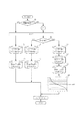
図14に処理フロー、図13に墨版補償のための初期化処理を示す。 FIG. 14 shows a processing flow, and FIG. 13 shows an initialization process for black plate compensation.
図14において、まず墨版補償のON/OFFが判断される(41)。 In FIG. 14, it is first determined whether or not the black plate compensation is ON / OFF (41).
墨版補償がOFFの場合には、ソース・プロファイル11のAToBxTagとデスティネーション・プロファイル12のBToAxTagを利用して、一般的なCMYK値からCMYK値への変換が行なわれる。ここで、K単色が入力されたとしても、出力は墨版生成の特性によって決定されたCMYK値(K単色以外)となる。
When the black plate compensation is OFF, conversion from a general CMYK value to a CMYK value is performed using AToBxTag of the source profile 11 and BToAxTag of the
一方、墨版補償がONの場合には、墨版補償のための初期化処理31が実行される。
On the other hand, when the black plate compensation is ON, an
以下、墨版補償のための初期化処理31の流れについて説明する(図13参照)。
Hereinafter, the flow of the
先ず、デスティネーション側のCMYKプロファイル12からAtoBxTagを読み込む(32)。AToBxTagにはデスティネーション側デバイスのCMYK値からPCSへの色変換(例えば、CMYK値からLab値)がLUT等で記述されている。
First, AtoBxTag is read from the CMYK
次に、AToBxTagの色変換の入力として、K単色(0,0,0,K)を擬似的に入力(例えば、K=0〜255)することにより、K単色(K=0〜255)に対するLab値を得ることができる。ここで、必要となるのはL*値(明度情報)だけなので、a*,b*は無視する(33)。なお、PCSがXYZ値の場合にはLab値へ変換する。 Next, K single color (0, 0, 0, K) is pseudo-input (for example, K = 0 to 255) as an input for color conversion of AToBxTag, so that K single color (K = 0 to 255) is input. Lab values can be obtained. Here, since only the L * value (lightness information) is required, a * and b * are ignored (33). If PCS is an XYZ value, it is converted to a Lab value.
これにより、グラフ34に示されるようなK−L特性が得られる。
Thereby, the KL characteristic as shown in the
次に、K−L特性(グラフ34)の逆変換を行い、L−K特性(グラフ36)を得る(35)。ここで、L−K特性は明度L*に相当するK単色の値を示す。 Next, the KL characteristic (graph 34) is inversely converted to obtain the LK characteristic (graph 36) (35). Here, the LK characteristic indicates a K monochrome value corresponding to the lightness L *.
以上の墨版補償のための初期化処理31が終了すると、各CMYK値の入力に対して、K単色か否かが判断される(42)。
When the above-described
入力のCMYK値がC!=0、またはM!=0、またはY!=0の場合(CMYのいずれかが0以外の値を有する場合)、入力のCMYK値はK単色以外と判断され、ソース・プロファイル11のAToBxTagとデスティネーション・プロファイル12のBToAxTagを利用して、一般的なCMYK値からCMYK値への変換が行なわれる。
The input CMYK value is C! = 0 or M! = 0 or Y! When = 0 (when any of CMY has a value other than 0), the input CMYK value is determined to be other than K single color, and AToBxTag of the source profile 11 and BToAxTag of the
一方、入力のCMYK値がC=M=Y=0の場合には、入力のCMYK値がK単色と判断される。 On the other hand, when the input CMYK value is C = M = Y = 0, the input CMYK value is determined to be K monochrome.
K単色に対しては、ソース・プロファイル11のAToBxTagと、墨版補償のための初期化処理31で得られたL−K特性が適用される。つまり、AToBxTagによってソース側K単色に対するLab値(または、XYZ値)が得られ、L−K特性によってデスティネーション側K単色が得られることになる(PCSがXYZ値の場合にはLab値へ変換する)。
従来の墨版処理では、初期化処理31によって得られたL−K特性においてデスティネーション・プロファイル12のBToAxTagのような色空間圧縮が考慮されていないため、L−K特性を使用するK単色用処理とBToAxTagを使用するK単色以外用処理との間でマッチング結果の明度でズレを生じる場合がある。
In the conventional black plate process, color space compression like BToAxTag of the
本願請求項1記載の発明は、入力色データを黒色成分を含む複数の色成分で示される出力データに変換する色処理方法であって、デスティネーションプロファイルに応じたデバイス依存のデータからデバイス非依存のデータに変換する第1の変換データから、明るさ成分値を黒色成分値に変換する明るさ成分−黒色成分変換データを生成し、入力色データが無彩色を示す色データであるか否かを判定し、前記入力色データが無彩色を示す色データであると判定された場合は、明るさ成分−黒色成分変換データを用いて、前記入力色データを前記黒色成分以外の色成分が0である 出力色ーデータに変換する色処理方法であり、前記変換は、前記入力色データが無彩色を示す色データであると判定された場合は、ソースプロファイルに応じたデバイス依存のデータからデバイス非依存のデータに変換する第2の変換データを用いて、前記入力色データをデバイス非依存のデータに変換し、前記デスティネーションプロファイルに応じたデバイス非依存のデータからデバイス依存のデータに変換する第3の変換データを用いて、前記変換されたデバイス非依存のデータをデスティネーションデバイス依存のデータに変換し、前記第1の変換データを用いて、前記変換されたデスティネーションデバイス依存のデータをデバイス非依存のデータに変換し、前記明るさ成分−黒色成分変換データを用いて、前記第1の変換データを用いて変換されたデスティネーションデバイス非依存のデータの明るさ成分の明度から前記出力色データの黒色成分の値を求め、前記入力色データが無彩色を示す色データでないと判定された場合は、前記第2の変換データおよび前記第3の変換データを用いて、入力色データを黒色成分を含む複数の色成分で示される出力データに変換することを特徴とする。
The invention described in
本願請求項2記載の発明は、入力色データを黒色成分を含む複数の色成分で示される出力データに変換する色処理方法であって、デスティネーションプロファイルに応じたデバイス依存のデータからデバイス非依存のデータに変換する第1の変換データから、明るさ成分値を黒色成分値に変換する明るさ成分−黒色成分変換データを生成し、入力色データが無彩色を示す色データであるか否かを判定し、前記入力色データが無彩色を示す色データであると判定された場合は、明るさ成分−黒色成分変換データを用いて、前記入力色データを前記黒色成分以外の色成分が0である出力色ーデータに変換する色処理方法であり、前記変換は、前記入力色データが無彩色を示す色データであると判定された場合は、ソースプロファイルに応じたデバイス依存のデータからデバイス非依存のデータに変換する第2の変換データを用いて、入力色データをデバイス非依存のデータに変換し、デスティネーションデバイスの色再現範囲に応じた色空間圧縮処理を、前記変換されたデバイス非依存データに対して行い、前記明るさ成分−黒色成分変換データを用いて、前記前記色空間圧縮されたデータの明度から前記出力色データの黒色成分の値を求め、前記入力色データが無彩色を示す色データでないと判定された場合は、前記第2の変換データ、前記色空間圧縮処理、およびデバイス非依存データをデスティネーションデバイス依存のデータに変換する第3の変換データを用いて、前記入力色データを黒色成分を含む複数の色成分で示される出力データに変換することを特徴とする色処理方法。
The invention described in
本発明によれば、出力デバイスの色再現範囲に基づき、無彩色の入力色を黒単色で再現することができる。 According to the present invention, an achromatic input color can be reproduced as a single black color based on the color reproduction range of the output device.
(実施例1)
以下、色空間圧縮処理を考慮した墨版補償について説明する。
Example 1
Hereinafter, the black plate compensation considering the color space compression processing will be described.
<色空間圧縮処理を考慮したCMYK値からCMYK値への色変換における墨版補償>
図1を用いて色空間圧縮処理を考慮したCMYK値からCMYK値への色変換における墨版補償について説明する。なお、初期化処理については図13と同一である。また、図1において、図14と同一の処理を行うところについては同一の符号を付けるとともに説明を割愛する。
<Black compensation in color conversion from CMYK values to CMYK values considering color space compression processing>
The black plate compensation in color conversion from CMYK values to CMYK values in consideration of color space compression processing will be described with reference to FIG. The initialization process is the same as in FIG. Further, in FIG. 1, the same processing as in FIG. 14 is denoted by the same reference numerals and description thereof is omitted.
図14の処理では、初期化処理31によって得られたL−K特性においてデスティネーション・プロファイル12のBToAxTagのような色空間圧縮が考慮されていないため、L−K特性を使用するK単色用処理とBToAxTagを使用するK単色以外用処理との間でマッチング結果の明度でズレを生じる場合がある。
In the process of FIG. 14, since the color space compression like BToAxTag of the
この点を改善するために、図1に示されるように、墨版補償がONであり、かつ入力色データがK単色である場合は(すなわち、入力色が無彩色の場合)、ソースプロフィル11のAtoBxTagを用いて、入力色データをLab値に変換する。次に、デスティネーション・プロファイル12のBToAxTagとAToBxTagによる処理を行う。
In order to improve this point, as shown in FIG. 1, when the black plate compensation is ON and the input color data is K single color (that is, the input color is an achromatic color), the source profile 11 The input color data is converted into Lab values using AtoBxTag. Next, processing by the
デスティネーション・プロファイル12のAtoBxTagを用いて求められたLab値のL値に対して、初期化31で求められたL−K特性(グラフ36)を用いてK値を算出する。
For the L value of the Lab value obtained using AtoBxTag of the
デスティネーション・プロファイル12のBtoAxTagは、デスティネーションデバイスの色再現範囲に基づく色空間圧縮処理が考慮されている。したがって、本実施例によれば、色空間圧縮後の明度に対してL−K特性を適用することができる。よって、L−K特性を使用するK単色用処理とBToAxTagを使用するK単色以外用処理との間でマッチング結果の明度を合わせることができる。
The BtoAxTag of the
なお、デスティネーション・プロファイル12のBToAxTagとAToBxTagによる処理は、デスティネーション・プロファイル12にgamutTagが含まれていればgamutTagによる処理を優先することもできる。
It should be noted that the processing by BmutAxTag and AToBxTag of the
<色空間圧縮処理を考慮したRGB値からCMYK値への色変換における墨版補償>
ソース・プロファイルがモニタ用プロファイルの場合には、デバイス依存色からPCSへ変換するための、3x3マトリクスとガンマ特性が格納されている。
<Black compensation in color conversion from RGB values to CMYK values in consideration of color space compression processing>
When the source profile is a monitor profile, a 3 × 3 matrix and gamma characteristics for conversion from device-dependent colors to PCS are stored.
図2に、RGB値からCMYK値への色変換における墨版補償における処理フローを示す。なお、図1と同様の処理については、同一の符号を付け説明を割愛する。 FIG. 2 shows a processing flow in black plate compensation in color conversion from RGB values to CMYK values. In addition, about the process similar to FIG. 1, the same code | symbol is attached | subjected and description is omitted.
処理内容はCMYK値からCMYK値への色変換とほぼ同じであるが、K単色(無彩色)か否かを判断するのではなく、R=G=Bか否かが判断される(52)。 The processing contents are almost the same as the color conversion from the CMYK value to the CMYK value, but it is not determined whether or not the color is a single K color (achromatic color), but is determined whether or not R = G = B (52). .
また、ソース・プロファイル11には3x3マトリクスとガンマ特性が格納されており、ガンマ特性によりデバイスRGBからリニアRGBへ変換され、3x3マトリクスによりリニアRGBからXYZ値へ変換される。XYZからLabへの変換は公知の変換方法に基づき変換される。なお、図1とでは、格納されている変換データが異なるが、カラーマッチングにおけるソースプロファイルを用いた処理としては同一の意味であるので、同一の符号を付けている。 The source profile 11 stores a 3 × 3 matrix and a gamma characteristic, and the device RGB is converted to linear RGB by the gamma characteristic, and the linear RGB is converted to XYZ value by the 3 × 3 matrix. Conversion from XYZ to Lab is performed based on a known conversion method. Although the conversion data stored in FIG. 1 is different from that in FIG. 1, the processing using the source profile in color matching has the same meaning, and thus the same reference numeral is given.
<色空間圧縮処理を考慮したGRAY値からCMYK値への色変換における墨版補償>
ソース・プロファイルがGRAY用プロファイルの場合には、デバイス依存色からPCSへ変換するための、1D LUT等が格納されている。
<Black compensation in color conversion from GRAY value to CMYK value considering color space compression processing>
When the source profile is a GRAY profile, a 1D LUT or the like for converting device-dependent colors to PCS is stored.
図3にGRAY値からCMYK値への色変換における墨版補償における処理フローを示す。なお、図1と同様の処理については、同一の符号を付け説明を割愛する。 FIG. 3 shows a processing flow in the black plate compensation in the color conversion from the GRAY value to the CMYK value. In addition, about the process similar to FIG. 1, the same code | symbol is attached | subjected and description is omitted.
処理内容はCMYK値からCMYK値への色変換とほぼ同じであるが、K単色か否かを判断するのではなく、墨版補償ONの場合には自動的にK単色出力とする。 The processing contents are almost the same as the color conversion from the CMYK value to the CMYK value. However, it is not determined whether the color is K single color, but is automatically set to K single color output when the black plate compensation is ON.
ソース・プロファイル11へは1D LUTが格納されており、1D LUTによりデバイスGRAYから輝度値へ変換され、白色点のXYZ値を積算することにより輝度値からXYZ値へ変換される。 A 1D LUT is stored in the source profile 11. The 1D LUT converts the device GRAY to a luminance value, and converts the luminance value into the XYZ value by integrating the XYZ values of the white point.
以上説明したように、本実施例によれば、墨版補償がONであり、入力色データが黒単色である場合に、出力デバイス(デスティネーションデバイス)の色再現範囲を考慮して黒単色の出力データに変換することができる。よって、L−K特性を使用するK単色用処理とBToAxTagを使用するK単色以外用処理との間でマッチング結果の明度を合わせることができる。 As described above, according to the present embodiment, when the black plate compensation is ON and the input color data is a single black color, the black single color is considered in consideration of the color reproduction range of the output device (destination device). Can be converted to output data. Therefore, the brightness of the matching result can be matched between the K single color process using the LK characteristic and the non-K single color process using BToAxTag.
(実施例2)
色知覚モデルは、観察条件VC1(W1を含む)下でのXYZ値を観察条件VC2(W2を含む)下のXYZ値に変換するために、例えばCIE CAM97s、CAM02のような人間の色知覚空間QMH(またはJCH)を利用して変換する方法である。ここで、QMHのQはbrightness、Mはcolourfulness、Hはhuequadratureまたはhueangleを表し、JCHのJはlightness、Cはchroma、Hはhuequadratureまたはhueangleを表す。この変換方法をLabの均等色空間へ適用すると、Von Kries変換と同様に、W1下でのLab値とW2下でのLab値は一致しない。例えば、W1(Xw1,Yw1,Zw1)下でのサンプルのXYZ値を(X1,Y1,Z1)、W2(Xw2,Yw2,Zw2)下でのサンプルのXYZ値を(X2,Y2,Z2)とするとき、色知覚モデルによれば次の変換が行われる:
(X1,Y1,Z1)→[CIE CAM97s順変換]→(Q,M,H)または(J,C,H)→[CIE CAM97s逆変換]→(X2,Y2,Z2)色知覚モデルを利用することによって、異なる観察条件下でのカラーマッチングを実現した例を図4に示す。
(Example 2)
The color perception model is a human color perception space such as CIE CAM97s, CAM02, for example, for converting XYZ values under the viewing condition VC1 (including W1) into XYZ values under the viewing condition VC2 (including W2). This is a conversion method using QMH (or JCH). Here, Q of QMH represents brightness, M represents colorfullness, H represents huequadture or hueangle, JCH of JCH represents lightness, C represents chroma, and H represents huequature or hueangle. When this conversion method is applied to the Lab uniform color space, the Lab value under W1 and the Lab value under W2 do not match as in the Von Kries conversion. For example, the XYZ value of the sample under W1 (Xw1, Yw1, Zw1) is (X1, Y1, Z1), and the XYZ value of the sample under W2 (Xw2, Yw2, Zw2) is (X2, Y2, Z2). When doing so, according to the color perception model, the following transformations are performed:
(X1, Y1, Z1) → [CIE CAM97s forward conversion] → (Q, M, H) or (J, C, H) → [CIE CAM97s inverse conversion] → (X2, Y2, Z2) color perception model is used FIG. 4 shows an example in which color matching under different observation conditions is realized.
<観察条件を考慮したCMYK値/RGB値/GRAY値からCMYK値への色変換における墨版補償>
観察条件を考慮した場合、基本的な処理フローは図14と同じであるが、墨版補償のための初期化処理31、及びソース・プロファイル11やデスティネーション・プロファイル12に対する処理において観察条件を考慮する必要がある。
<C Black Compensation in Color Conversion from CMYK Value / RGB Value / GRAY Value to CMYK Value Considering Observation Conditions>
When the observation conditions are considered, the basic processing flow is the same as in FIG. 14, but the observation conditions are considered in the
墨版補償においては、予め基準となる観察条件(例えば、D50でオフィスの観察条件)を設定しておき、初期化処理31のK−L特性導出34の際に観察条件を考慮して、プロファイル内に設定してある観察条件から基準観察条件下のL値となるように色知覚モデルを適用する。
In the black plate compensation, a reference observation condition (for example, an office observation condition at D50) is set in advance, and the profile is considered in consideration of the observation condition when the KL
実際にK単色の入力色データに対して処理を行なう場合は、ソース・プロファイル11のAtoBxTag11によって求められたソース・プロファイル11の観察条件下のL値を、K−L特性導出34の際に設定した基準観察条件下のL値に、色知覚モデルを用いて変換する。そして、基準観察条件下のL値に対して、初期化処理31によって導出された基準観察条件下のL−K特性を適用することによってK単色を求める。
When actually processing the input color data of K single color, the L value under the observation condition of the source profile 11 obtained by the AtoBxTag 11 of the source profile 11 is set when the KL
墨版補償OFFの場合やK単色以外の入力に対しては、図4と同様の処理を適用することによって観察条件を考慮することができる。 The observation conditions can be considered by applying the same processing as in FIG. 4 to the case where the black plate compensation is OFF or the input other than the K single color.
また、CMYK値の場合と、RGB値/GRAY値の場合における処理の違いは、実施例1と同じである。よって、CMYK値における処理手順を、RGB値/GRAY値の場合における処理手順に適用することによりCMYK値と同様に観察条件を考慮した墨版補償を実現することができる。 Further, the difference in processing between the case of CMYK values and the case of RGB values / GRAY values is the same as in the first embodiment. Therefore, by applying the processing procedure for the CMYK value to the processing procedure for the RGB value / GRAY value, it is possible to realize black plate compensation in consideration of the observation conditions as in the case of the CMYK value.
(実施例3)
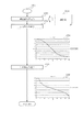
図5に人間の色知覚空間上での色空間圧縮を用いたカラーマッチングの概念図を示す。
(Example 3)
FIG. 5 shows a conceptual diagram of color matching using color space compression on a human color perception space.
まず、入力側デバイスモデル1101及び出力側デバイスモデル1106を、測色値1111または測色値1114を用いて生成する。デバイスモデルには順方向変換(ICCプロファイルのAToB1Tagの処理に相当)と逆方向変換(ICCプロファイルのBToA1Tagの処理に相当)が存在する。デバイス・キャラクタライゼーションとは、測色値に基づき、順方向変換(デバイス依存のデータからデバイス非依存のデータへの変換)を行うための変換データおよび逆方向変換(デバイス非依存のデータからデバイス依存のデータへの変換)を行うための変換データを生成する処理である。
First, the input
順方向変換データの生成は、デバイス色と測色値の対応関係を記述した測色値ファイル(1111又は1114)を読み込み、デバイス色からXYZ値への変換を行う多次元LUTもしくは変換式を生成する。逆方向変換データの生成は、順方向変換の結果を利用して、順方向多次元LUTの逆引きや回帰分析法による多項式パラメータの最適化等によってXYZ値からデバイス色への変換を行う多次元LUTもしくは変換式を生成する。 The forward conversion data is generated by reading a colorimetric value file (1111 or 1114) that describes the correspondence between device colors and colorimetric values, and generating a multidimensional LUT or conversion formula that converts device colors to XYZ values. To do. The reverse conversion data is generated by converting the XYZ values into device colors by using the result of the forward conversion and performing reverse conversion of the forward multidimensional LUT or optimizing the polynomial parameters by the regression analysis method. LUT or conversion formula is generated.
ここで、測色値やデバイス非依存の色空間はXYZに限定される必要はなく、Lab,Luv等の色空間であっても構わない。 Here, the color space that does not depend on the colorimetric value or the device need not be limited to XYZ, and may be a color space such as Lab or Luv.
次に、人間の色知覚空間上での入力側デバイスの色再現範囲1107(又は1108)と出力側デバイスの色再現範囲1109(又は1110)を求める。Relativeモードの場合には人間の色知覚空間としてJChが選択され、Absoluteモードの場合にはQMhが選択される。 Next, the color reproduction range 1107 (or 1108) of the input side device and the color reproduction range 1109 (or 1110) of the output side device in the human color perception space are obtained. In the case of the relative mode, JCh is selected as the human color perception space, and in the case of the absolute mode, QMh is selected.
入力側デバイスの色再現範囲1107(又は1108)は、測色値ファイル1111の測色値やデバイスモデル1101の順方向変換の結果から得られる入力側デバイス全体のXYZ値に対して色知覚モデルの順方向変換を適用し、得られたJCh(又はQMh)値の3次元凸包(Convex Hull)の作成等を行なうことによって求めることができる。色再現範囲は、得られたJCh(又はQMh)値を包含する3次元立体である。
The color gamut 1107 (or 1108) of the input side device is a color perception model for the XYZ values of the entire input side device obtained from the colorimetric values of the
出力側デバイスの色再現範囲1109(又は1110)も測色値ファイル1114の測色値やデバイスモデル1106の順方向変換の結果から得られる出力側デバイス全体のXYZ値に対して色知覚モデルの順方向変換を適用し、得られたJCh(又はQMh)値の3次元凸包(Convex Hull)の作成等を行なうことによって求めることができる。
The color reproduction range 1109 (or 1110) of the output-side device is also the order of the color perception model with respect to the XYZ values of the entire output-side device obtained from the colorimetric values of the
ここで、入力側の色知覚モデルには入力側観察条件1112、出力側の色知覚モデルには出力側観察条件1113をそれぞれ設定する。色知覚モデルとしてはCIECAM02、CIECAM97s等に限定される必要はなく、人間の色知覚パラメータJ,C,Q,M,h,Hを予測できる色知覚モデルであれば別の色知覚モデルであっても構わない。
Here, the input side viewing condition 1112 is set for the input side color perception model, and the output
このように生成された入力側および出力側のデバイスモデルおよび色再現範囲に基づき、カラーマッチングを行う。 Based on the input-side and output-side device models and the color reproduction range thus generated, color matching is performed.
人間の色知覚空間JCh上での色空間圧縮を考慮した、入力側デバイス色から出力側デバイス色への色変換は、以下の処理によって行なうことができる。 Color conversion from the input device color to the output device color in consideration of color space compression on the human color perception space JCh can be performed by the following processing.
まず入力色に対して入力側デバイスモデル1101の順方向変換を適用してXYZ値を求める。次に入力側観察条件1112に基づく色知覚モデル1102の順方向変換を適用してJCh値を求める。次に、入力側デバイスの色再現範囲1107と出力側デバイスの色再現範囲1109とに基づきら色空間圧縮1103を行う。色空間圧縮後のJCh値を出力側観察条件1113に基づく色知覚モデル1105の逆方向変換を適用してXYZ値を求める。そして、出力側デバイスモデル1106の逆方向変換を適用して出力色を求める。
First, the XYZ value is obtained by applying the forward conversion of the
人間の色知覚空間QMh上での色空間圧縮を考慮した、入力側デバイス色から出力側デバイス色への色変換も同様に、入力側デバイスの色再現範囲1108、出力側デバイスの色再現範囲1110、及び色空間圧縮1104等を用いて行うことができる。
Similarly, the color conversion from the input device color to the output device color in consideration of the color space compression on the human color perception space QMh, similarly, the color reproduction range 1108 of the input device and the
図4に示すカラーマッチングによれば、カラーマッチングの対象となる入力側デバイスおよび出力側デバイスの色再現範囲の組み合わせに対して最適な色空間圧縮を行うことができる。 According to the color matching shown in FIG. 4, optimal color space compression can be performed for a combination of color reproduction ranges of an input side device and an output side device to be color matched.
<人間の色知覚空間上での色空間圧縮を考慮したCMYK値/RGB値/GRAY値からCMYK値への色変換における墨版補償>
図5に示した人間の色知覚空間上での色空間圧縮を用いたカラーマッチングにおいて、墨版補償を実現する処理手順を説明する。
<Black Plate Compensation in Color Conversion from CMYK Value / RGB Value / GRAY Value to CMYK Value Considering Color Space Compression in Human Color Perception Space>
A processing procedure for realizing black plate compensation in color matching using color space compression in the human color perception space shown in FIG. 5 will be described.
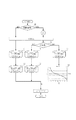
図6は本実施例における墨版補償のための初期化処理を示す。図7はCMYK入力、図8はRGB入力、図9はGRAY入力の場合の処理フローをそれぞれ示している。 FIG. 6 shows an initialization process for black plate compensation in this embodiment. FIG. 7 shows the processing flow for CMYK input, FIG. 8 for RGB input, and FIG. 9 for GRAY input.
図7、8、9におけるソース・プロファイル1101は、図5における入力側デバイスモデル(入力側順方向変換データ)1101に対応する。デスティネーション・プロファイル1106は、出力側デバイスモデル(出力側逆変換データ)1106に対応する。図5と図7、8,9では、同一の符号のものは表記方法が異なっていたとしても同一の処理を示している。
まず、墨版補償のON/OFFが判断される(1301)。
The
First, ON / OFF of the black plate compensation is determined (1301).
墨版補償がOFFの場合には、図5の概念図に示される処理が行なわれる。 When the black plate compensation is OFF, the process shown in the conceptual diagram of FIG. 5 is performed.
一方、墨版補償がONの場合には、墨版補償のための初期化処理1201が実行される。
On the other hand, when the black plate compensation is ON, an
図6に墨版補償のための初期化処理を示す。 FIG. 6 shows an initialization process for black plate compensation.
まず、デスティネーション側デバイスの測色値ファイル1114を読み込み(1202)、測色値に線形補間等を適用してK単色に対する明度L*(又は輝度Y)特性を算出し、K―L特性(グラフ1204)を導出する(1203)。次に、K−L特性の逆変換となるL−K特性(グラフ1206)を導出する(1205)。
First, the
以上の墨版補償のための初期化処理1201が終了すると、入力色に対してK単色(CMYK入力時)、R=G=B(RGB入力時)か否かが判断される(1302)。
When the
入力色がK単色以外、R=G=B以外の場合には、墨版補償OFFと同様の処理を行い、ソース側デバイスの色再現範囲1107(又は1108)からをデスティネーション側デバイスの色再現範囲1109(又は1110)への色空間圧縮が行なわれる。図10(a)に、ソース側デバイスの色再現範囲1601、デスティネーション側デバイスの色再現範囲1602を示す。
When the input color is other than K single color and other than R = G = B, the same processing as the black plate compensation OFF is performed, and the color reproduction of the destination device is performed from the color reproduction range 1107 (or 1108) of the source device. Color space compression to the range 1109 (or 1110) is performed. FIG. 10A shows a
一方、入力色がK単色(CMYK入力時)、R=G=B(RGB入力時)、グレー(GRAY入力時)の場合には、墨版を補償するための処理を行う。 On the other hand, when the input color is K single color (when CMYK is input), R = G = B (when RGB is input), and gray (when GRAY is input), processing for compensating the black plate is performed.
ソース側デバイスの色再現範囲1107(又は1108)としてK単色、R=G=B、グレーの各入力色全域(例えば、8ビット入力の場合にはK=0〜255、R=G=B=0〜255、GRAY=0〜255)に対する色再現範囲(以下、無彩色再現範囲)1603、デスティネーション側デバイスの色再現範囲1109(又は1110)としてK単色の出力色全域(8ビット出力の場合にはK=0〜255)に対する色再現範囲(以下、K単色再現範囲)1604を求める(図16(a)参照)。 As the color reproduction range 1107 (or 1108) of the source side device, the entire input colors of K, R = G = B, and gray (for example, K = 0 to 255 for 8-bit input, R = G = B = 0 to 255, GRAY = 0 to 255) color reproduction range (hereinafter referred to as achromatic color reproduction range) 1603, destination side device color reproduction range 1109 (or 1110), K single color output color whole area (in case of 8-bit output) For K = 0 to 255), a color reproduction range (hereinafter referred to as K single color reproduction range) 1604 is obtained (see FIG. 16A).
人間の色知覚空間上での色空間圧縮1103(又は1104)では、入出力の色再現範囲の明度(又は輝度)を考慮しながら、無彩色再現範囲1603がK単色再現範囲1604に収まるように写像(色空間圧縮1103又は1104)が行なわれる。
In the color space compression 1103 (or 1104) on the human color perception space, the achromatic
この際、入力色がK単色以外、R=G=B以外の場合の色空間圧縮(以下、有彩色空間圧縮)とK単色、R=G=Bの場合の色空間圧縮(以下、無彩色空間圧縮)では明度(又は輝度)範囲が異なるだけでなく、圧縮方式も異なる。よって、有彩色空間圧縮と無彩色空間圧縮の出力結果では明度(又は輝度)にズレを生じる場合がある。例えば、有彩色空間圧縮の色空間圧縮がPerceptualである場合には、非線形な明度圧縮が行なわれている可能性があるため、無彩色空間圧縮が線形な明度圧縮である場合には、入力色として明度が等しい色であっても出力色として明度が異なった色となる。よって、無彩色空間圧縮において、有彩色空間圧縮と明度(又は輝度)差が少なく、ある程度の階調性を保った色空間圧縮を実現するためには、例えば、入力色の明度(又は輝度)が、K単色再現範囲1603の(α+β)%以内に相当する場合には、有彩色空間圧縮によって得られた明度(又は輝度)をL−K(又はY−K)特性によって出力し、(α+β)%以外に相当する場合には、無彩色再現範囲の入力色がK単色再現範囲に収まるような写像によって得られた明度(又は輝度)をL−K(又はY−K)特性によって出力すればよい。ここで、α%及びβ%はK単色再現範囲1603全体に対して50%の点からの割合を示しており、無彩色再現範囲の最大明度をJmax1、最小明度をJmin1、K単色再現範囲の最大明度をJmax2、最小明度をJmin2とすれば、α%及びβ%は例えば、以下のように決定される:
In this case, color space compression when the input color is other than K single color and R = G = B (hereinafter referred to as chromatic color space compression) and color space compression when K is single color and R = G = B (hereinafter referred to as achromatic color). Spatial compression) not only has different brightness (or luminance) ranges, but also different compression methods. Therefore, there may be a deviation in brightness (or luminance) in the output results of chromatic color space compression and achromatic color space compression. For example, when the color space compression of the chromatic color space compression is Perceptual, there is a possibility that non-linear lightness compression is performed. Therefore, when the achromatic color space compression is linear lightness compression, the input color As a result, even if the colors have the same brightness, the output colors have different brightness. Therefore, in achromatic color space compression, in order to realize color space compression with little difference in brightness (or luminance) from chromatic color space compression and maintaining a certain degree of gradation, for example, lightness (or luminance) of an input color. Is equivalent to within (α + β)% of the K single

図16(b)は有彩色空間圧縮がColorimetricであって、K単色再現範囲1604のα%以外の部分に相当する無彩色再現範囲1603の入力色が線形に色空間圧縮されている例を示したものである。ここで、K単色再現範囲1604のα%以外の部分に相当する色空間圧縮は線形である必要はなく、有彩色空間圧縮(α%以内の部分)と勾配が連続的に接続される非線形な特性であっても構わない。
FIG. 16B shows an example in which the chromatic color space compression is Colorimetric and the input color of the achromatic
このような色空間圧縮を行い(1103)、CAM−1を行う(1105)ことにより得られたL値に対して、L−K特性1206を用いて変換しK値を求める。 The L value obtained by performing such color space compression (1103) and CAM- 1 (1105) is converted using the LK characteristic 1206 to obtain the K value.
本実施例の処理によれば、入力側K単色、R=G=B、GRAYに対する色再現範囲と出力側K単色、R=G=B、GRAYに対する色再現範囲を考慮して色空間圧縮を行う。よって、高精度な墨版処理を実現することができる。 According to the processing of this embodiment, color space compression is performed in consideration of the color reproduction range for the input side K single color, R = G = B, GRAY and the color reproduction range for the output side K single color, R = G = B, GRAY. Do. Therefore, highly accurate black plate processing can be realized.
(変形例)
墨版補償を適用するか否かの設定は、カラーリストに対するカラーマッチング関数(MatchColors)、ラスタ画像に対するカラーマッチング関数(MatchPixmap)において独立に設定することができる。
(Modification)
Whether to apply the black plate compensation can be set independently in the color matching function (MatchColors) for the color list and the color matching function (MatchPixmap) for the raster image.
図11に示すように、カラーマッチングを行なう際に、墨版補償を適用するか否かはユーザ・インターフェイスを介して、各オブジェクトの種類ごとに選択しても構わない(図7)。各補正はチェックボックスをONにすることによって墨版補償がONとなり、GRAY入力の場合はGRAY値からCMYKへのカラーマッチング、RGB入力の場合はRGB値からCMYK値へのカラーマッチング、CMYK入力の場合はCMYK値からCMYK値へのカラーマッチングにおいてのみ有効となる。 As shown in FIG. 11, when color matching is performed, whether to apply black plate compensation may be selected for each object type via the user interface (FIG. 7). For each correction, the black plate compensation is turned on by turning on the check box. In the case of GRAY input, color matching from GRAY value to CMYK, in the case of RGB input, color matching from RGB value to CMYK value, CMYK input The case is effective only in color matching from CMYK values to CMYK values.
前述した実施例の機能を実現する様に各種のデバイスを動作させる様に該各種デバイスと接続された装置あるいはシステム内のコンピュータに、前記実施例の機能を実現するためのソフトウエアのプログラムコードを供給し、そのシステムあるいは装置のコンピュータ(CPUあるいはMPU)を格納されたプログラムに従って前記各種デバイスを動作させることによって実施したものも本発明の範疇に含まれる。 A program code of software for realizing the functions of the above-described embodiment is applied to an apparatus or a computer in the system connected to the various devices so as to operate the various devices so as to realize the functions of the above-described embodiments. What is implemented by operating the various devices in accordance with a program stored in a computer (CPU or MPU) of the system or apparatus supplied is also included in the scope of the present invention.
この場合、前記ソフトウエアのプログラムコード自体が前述した実施例の機能を実現することになり、そのプログラムコード自体、及びそのプログラムコードをコンピュータに供給するための手段、例えばかかるプログラムコードを格納した記憶媒体は本発明を構成する。 In this case, the program code of the software itself realizes the functions of the above-described embodiments, and the program code itself and means for supplying the program code to the computer, for example, a memory storing the program code The medium constitutes the present invention.
かかるプログラムコードを格納する記憶媒体としては例えばフロッピー(登録商標)ディスク、ハードディスク、光ディスク、光磁気ディスク、CD−ROM、磁気テープ、不揮発性のメモリカード、ROM等を用いることが出来る。 As a storage medium for storing the program code, for example, a floppy (registered trademark) disk, a hard disk, an optical disk, a magneto-optical disk, a CD-ROM, a magnetic tape, a nonvolatile memory card, a ROM, or the like can be used.
またコンピュータが供給されたプログラムコードを実行することにより、前述の実施形態の機能が実現されるだけではなく、そのプログラムコードがコンピュータにおいて稼働しているOS(オペレーティングシステム)、あるいは他のアプリケーションソフト等と共同して前述の実施例の機能が実現される場合にもかかるプログラムコードは本発明の実施形態に含まれることは言うまでもない。 Further, by executing the program code supplied by the computer, not only the functions of the above-described embodiments are realized, but also the OS (operating system) in which the program code is running on the computer, or other application software Needless to say, the program code is also included in the embodiment of the present invention even when the functions of the above-described embodiments are realized in cooperation with the embodiment.
更に供給されたプログラムコードが、コンピュータの機能拡張ボードやコンピュータに接続された機能拡張ユニットに備わるメモリに格納された後そのプログラムコードの指示に基づいてその機能拡張ボードや機能格納ユニットに備わるCPU等が実際の処理の一部または全部を行い、その処理によって前述した実施形態の機能が実現される場合も本発明に含まれることは言うまでもない。 Further, the supplied program code is stored in the memory provided in the function expansion board of the computer or the function expansion unit connected to the computer, and then the CPU provided in the function expansion board or function storage unit based on the instruction of the program code However, it is needless to say that the present invention also includes a case where the function of the above-described embodiment is realized by performing part or all of the actual processing.
Claims (7)
デスティネーションプロファイルに応じたデバイス依存のデータからデバイス非依存のデータに変換する第1の変換データから、明るさ成分値を黒色成分値に変換する明るさ成分−黒色成分変換データを生成し、
入力色データが無彩色を示す色データであるか否かを判定し、
前記入力色データが無彩色を示す色データであると判定された場合は、明るさ成分−黒色成分変換データを用いて、前記入力色データを前記黒色成分以外の色成分が0である出力色ーデータに変換する色処理方法であり、
前記変換は、
前記入力色データが無彩色を示す色データであると判定された場合は、
ソースプロファイルに応じたデバイス依存のデータからデバイス非依存のデータに変換する第2の変換データを用いて、前記入力色データをデバイス非依存のデータに変換し、
前記デスティネーションプロファイルに応じたデバイス非依存のデータからデバイス依存のデータに変換する第3の変換データを用いて、前記変換されたデバイス非依存のデータをデスティネーションデバイス依存のデータに変換し、
前記第1の変換データを用いて、前記変換されたデスティネーションデバイス依存のデータをデバイス非依存のデータに変換し、
前記明るさ成分−黒色成分変換データを用いて、前記第1の変換データを用いて変換されたデスティネーションデバイス非依存のデータの明るさ成分の明度から前記出力色データの黒色成分の値を求め、
前記入力色データが無彩色を示す色データでないと判定された場合は、
前記第2の変換データおよび前記第3の変換データを用いて、入力色データを黒色成分を含む複数の色成分で示される出力データに変換することを特徴とする色処理方法。 A color processing method for converting input color data into output data represented by a plurality of color components including a black component,
Generating brightness component-black component conversion data for converting the brightness component value into the black component value from the first conversion data for converting the device-dependent data according to the destination profile to the device-independent data;
Determine whether the input color data is color data indicating an achromatic color,
When it is determined that the input color data is a color data indicating an achromatic color, the input color data is output color having a color component other than the black component is 0 using brightness component-black component conversion data. -Color processing method to convert to data,
The transformation is
When it is determined that the input color data is color data indicating an achromatic color,
Converting the input color data into device-independent data using second conversion data for converting device-dependent data according to a source profile into device-independent data;
Using the third conversion data for converting the device-independent data corresponding to the destination profile into the device-dependent data, and converting the converted device-independent data into the destination device-dependent data;
Using the first converted data, the converted destination device dependent data is converted into device independent data,
Using the brightness component-black component conversion data, the value of the black component of the output color data is obtained from the brightness of the brightness component of the destination device-independent data converted using the first conversion data. ,
When it is determined that the input color data is not color data indicating an achromatic color,
A color processing method comprising: converting input color data into output data represented by a plurality of color components including a black component using the second conversion data and the third conversion data.
デスティネーションプロファイルに応じたデバイス依存のデータからデバイス非依存のデータに変換する第1の変換データから、明るさ成分値を黒色成分値に変換する明るさ成分−黒色成分変換データを生成し、
入力色データが無彩色を示す色データであるか否かを判定し、
前記入力色データが無彩色を示す色データであると判定された場合は、明るさ成分−黒色成分変換データを用いて、前記入力色データを前記黒色成分以外の色成分が0である出力色ーデータに変換する色処理方法であり、
前記変換は、
前記入力色データが無彩色を示す色データであると判定された場合は、
ソースプロファイルに応じたデバイス依存のデータからデバイス非依存のデータに変換する第2の変換データを用いて、入力色データをデバイス非依存のデータに変換し、
デスティネーションデバイスの色再現範囲に応じた色空間圧縮処理を、前記変換されたデバイス非依存データに対して行い、
前記明るさ成分−黒色成分変換データを用いて、前記前記色空間圧縮されたデータの明度から前記出力色データの黒色成分の値を求め、
前記入力色データが無彩色を示す色データでないと判定された場合は、
前記第2の変換データ、前記色空間圧縮処理、およびデバイス非依存データをデスティネーションデバイス依存のデータに変換する第3の変換データを用いて、前記入力色データを黒色成分を含む複数の色成分で示される出力データに変換することを特徴とする色処理方法。 A color processing method for converting input color data into output data represented by a plurality of color components including a black component,
Generating brightness component-black component conversion data for converting the brightness component value into the black component value from the first conversion data for converting the device-dependent data according to the destination profile to the device-independent data;
Determine whether the input color data is color data indicating an achromatic color,
When it is determined that the input color data is a color data indicating an achromatic color, the input color data is output color having a color component other than the black component is 0 using brightness component-black component conversion data. -Color processing method to convert to data,
The transformation is
When it is determined that the input color data is color data indicating an achromatic color,
Using the second conversion data that converts device-dependent data according to the source profile to device-independent data, the input color data is converted to device-independent data,
A color space compression process corresponding to the color reproduction range of the destination device is performed on the converted device-independent data,
Using the brightness component-black component conversion data , obtain the value of the black component of the output color data from the brightness of the color space compressed data,
When it is determined that the input color data is not color data indicating an achromatic color,
A plurality of color components including a black component using the second conversion data, the color space compression processing, and third conversion data for converting device-independent data into destination device-dependent data. A color processing method characterized by converting to output data indicated by
前記判定は、前記入力色データの黒色成分以外の色成分値が0であるか否かを判定することを特徴とする請求項1記載の色処理方法。 The input color data is represented by a plurality of color components including a black component,
The color processing method according to claim 1, wherein the determination includes determining whether a color component value other than a black component of the input color data is zero .
前記判定は、赤色成分値、青色成分値、緑色成分値が等しいか否かを判定することを特徴とする請求項1記載の色処理方法。 The input color data is indicated by red, blue and green components,
It said determining, a red component value, a blue component value, a color processing method according to claim 1, wherein the green component value is determined equal poetry not.
デスティネーションプロファイルに応じたデバイス依存のデータからデバイス非依存のデータに変換する第1の変換データから、明るさ成分値を黒色成分値に変換する明るさ成分−黒色成分変換データを生成する生成手段と、
入力色データが無彩色を示す色データであるか否かを判定する判定手段と、
前記入力色データが無彩色を示す色データであると判定された場合は、明るさ成分−黒色成分変換データを用いて、前記入力色データを前記黒色成分以外の色成分が0である出力色ーデータに変換する変換手段とを有し、
前記変換手段は、
前記入力色データが無彩色を示す色データであると判定された場合は、
ソースプロファイルに応じたデバイス依存のデータからデバイス非依存のデータに変換する第2の変換データを用いて、前記入力色データをデバイス非依存のデータに変換し、
前記デスティネーションプロファイルに応じたデバイス非依存のデータからデバイス依存のデータに変換する第3の変換データを用いて、前記変換されたデバイス非依存のデータをデスティネーションデバイス依存のデータに変換し、
前記第1の変換データを用いて、前記変換されたデスティネーションデバイス依存のデータをデバイス非依存のデータに変換し、
前記明るさ成分−黒色成分変換データを用いて、前記第1の変換データを用いて変換されたデスティネーションデバイス非依存のデータの明るさ成分から前記出力色データの黒色成分の値を求め、
前記入力色データが無彩色を示す色データでないと判定された場合は、
前記第2の変換データおよび前記第3の変換データを用いて、入力色データを黒色成分を含む複数の色成分で示される出力データに変換することを特徴とする色処理装置。 A color processing device that converts input color data into output data represented by a plurality of color components including a black component,
Generation means for generating brightness component-black component conversion data for converting a brightness component value into a black component value from first conversion data that converts device-dependent data according to the destination profile into device-independent data When,
Determining means for determining whether or not the input color data is color data indicating an achromatic color;
When it is determined that the input color data is a color data indicating an achromatic color, the input color data is output color having a color component other than the black component is 0 using brightness component-black component conversion data. -Conversion means for converting to data,
The converting means includes
When it is determined that the input color data is color data indicating an achromatic color,
Converting the input color data into device-independent data using second conversion data for converting device-dependent data according to a source profile into device-independent data;
Using the third conversion data for converting the device-independent data corresponding to the destination profile into the device-dependent data, and converting the converted device-independent data into the destination device-dependent data;
Using the first converted data, the converted destination device dependent data is converted to device independent data,
Using the brightness component-black component conversion data , obtain the value of the black component of the output color data from the brightness component of the destination device independent data converted using the first conversion data ,
When it is determined that the input color data is not color data indicating an achromatic color,
A color processing apparatus that converts input color data into output data represented by a plurality of color components including a black component, using the second conversion data and the third conversion data.
デスティネーションプロファイルに応じたデバイス依存のデータからデバイス非依存のデータに変換する第1の変換データから、明るさ成分値を黒色成分値に変換する明るさ成分−黒色成分変換データを生成する生成手段と、
入力色データが無彩色を示す色データであるか否かを判定する判定手段と、
前記入力色データが無彩色を示す色データであると判定された場合は、明るさ成分−黒色成分変換データを用いて、前記入力色データを前記黒色成分以外の色成分が0である出力色ーデータに変換する変換手段とを有し、
前記変換手段は、
前記入力色データが無彩色を示す色データであると判定された場合は、
ソースプロファイルに応じたデバイス依存のデータからデバイス非依存のデータに変換する第2の変換データを用いて、入力色データをデバイス非依存のデータに変換し、
デスティネーションデバイスの色再現範囲に応じた色空間圧縮処理を、前記変換されたデバイス非依存データに対して行い、
前記明るさ成分−黒色成分変換データを用いて、前記前記色空間圧縮されたデータの明度から前記出力色データの黒色成分の値を求め、
前記入力色データが無彩色を示す色データでないと判定された場合は、
前記第2の変換データ、前記色空間圧縮処理、およびデバイス非依存データをデスティネーションデバイス依存のデータに変換する第3の変換データを用いて、前記入力色データを黒色成分を含む複数の色成分で示される出力データに変換することを特徴とする色処理装置。 A color processing device that converts input color data into output data represented by a plurality of color components including a black component,
Generation means for generating brightness component-black component conversion data for converting a brightness component value into a black component value from first conversion data that converts device-dependent data according to the destination profile into device-independent data When,
Determining means for determining whether or not the input color data is color data indicating an achromatic color;
When it is determined that the input color data is a color data indicating an achromatic color, the input color data is output color having a color component other than the black component is 0 using brightness component-black component conversion data. -Conversion means for converting to data,
The converting means includes
When it is determined that the input color data is color data indicating an achromatic color,
Using the second conversion data that converts device-dependent data according to the source profile to device-independent data, the input color data is converted to device-independent data,
A color space compression process corresponding to the color reproduction range of the destination device is performed on the converted device-independent data,
Using the brightness component-black component conversion data , obtain the value of the black component of the output color data from the brightness of the color space compressed data,
When it is determined that the input color data is not color data indicating an achromatic color,
A plurality of color components including a black component using the second conversion data, the color space compression processing, and third conversion data for converting device-independent data into destination device-dependent data. A color processing apparatus characterized by converting into output data indicated by
Priority Applications (1)
| Application Number | Priority Date | Filing Date | Title |
|---|---|---|---|
| JP2005053443A JP4411228B2 (en) | 2005-02-28 | 2005-02-28 | Color processing method and apparatus |
Applications Claiming Priority (1)
| Application Number | Priority Date | Filing Date | Title |
|---|---|---|---|
| JP2005053443A JP4411228B2 (en) | 2005-02-28 | 2005-02-28 | Color processing method and apparatus |
Publications (3)
| Publication Number | Publication Date |
|---|---|
| JP2006238336A JP2006238336A (en) | 2006-09-07 |
| JP2006238336A5 JP2006238336A5 (en) | 2008-04-10 |
| JP4411228B2 true JP4411228B2 (en) | 2010-02-10 |
Family
ID=37045457
Family Applications (1)
| Application Number | Title | Priority Date | Filing Date |
|---|---|---|---|
| JP2005053443A Expired - Fee Related JP4411228B2 (en) | 2005-02-28 | 2005-02-28 | Color processing method and apparatus |
Country Status (1)
| Country | Link |
|---|---|
| JP (1) | JP4411228B2 (en) |
Families Citing this family (1)
| Publication number | Priority date | Publication date | Assignee | Title |
|---|---|---|---|---|
| US7706022B2 (en) * | 2006-06-12 | 2010-04-27 | Kabushiki Kaisha Toshiba | Image forming apparatus and image forming method |
-
2005
- 2005-02-28 JP JP2005053443A patent/JP4411228B2/en not_active Expired - Fee Related
Also Published As
| Publication number | Publication date |
|---|---|
| JP2006238336A (en) | 2006-09-07 |
Similar Documents
| Publication | Publication Date | Title |
|---|---|---|
| KR100902700B1 (en) | Color processing method and color processing apparatus | |
| US7616361B2 (en) | Color processing apparatus and its method | |
| CN101252635B (en) | Image processing apparatus and image processing method | |
| JP2009521840A (en) | Limited color palette in color space | |
| US7312891B2 (en) | Image processing method and apparatus | |
| US7230737B1 (en) | Image processing method and apparatus | |
| WO2003003715A1 (en) | Image processing device, image processing method, program, and recording medium | |
| KR100921037B1 (en) | Image signal processing method and image signal processing apparatus | |
| JP3984852B2 (en) | Color processing apparatus and method | |
| JP3420560B2 (en) | Image processing method and recording medium | |
| KR20050109663A (en) | Method and apparatus for creating profile | |
| JP3870143B2 (en) | Information processing method | |
| JP4910557B2 (en) | Color conversion apparatus, color conversion method, color conversion program, color conversion coefficient creation apparatus, color conversion coefficient creation method, and color conversion coefficient creation program | |
| JP4411228B2 (en) | Color processing method and apparatus | |
| JP2006340107A (en) | Image processing method, profile generating method, and image processing apparatus | |
| JP4533291B2 (en) | Color processing method and apparatus | |
| JP2007174126A (en) | Image processing apparatus and method | |
| JP2011205467A (en) | Color processing apparatus, and program | |
| JP2007243957A (en) | System, method and program for extracting gray information from color image data | |
| JP5112234B2 (en) | Image processing apparatus, image processing method, program, and recording medium | |
| JP4472594B2 (en) | Image data color conversion apparatus, color conversion method, and color conversion program | |
| JP3667171B2 (en) | Image processing method, apparatus, and recording medium | |
| JP3535778B2 (en) | Image processing method, apparatus and recording medium | |
| JP2002262115A (en) | Image processor, color conversion definition generating device, image processing method, color conversion definition generating method, and storage medium | |
| JP2009284261A (en) | Color processing device, method and program |
Legal Events
| Date | Code | Title | Description |
|---|---|---|---|
| A521 | Request for written amendment filed |
Free format text: JAPANESE INTERMEDIATE CODE: A523 Effective date: 20080226 |
|
| A621 | Written request for application examination |
Free format text: JAPANESE INTERMEDIATE CODE: A621 Effective date: 20080226 |
|
| A977 | Report on retrieval |
Free format text: JAPANESE INTERMEDIATE CODE: A971007 Effective date: 20090528 |
|
| A131 | Notification of reasons for refusal |
Free format text: JAPANESE INTERMEDIATE CODE: A131 Effective date: 20090602 |
|
| A521 | Request for written amendment filed |
Free format text: JAPANESE INTERMEDIATE CODE: A523 Effective date: 20090731 |
|
| TRDD | Decision of grant or rejection written | ||
| A01 | Written decision to grant a patent or to grant a registration (utility model) |
Free format text: JAPANESE INTERMEDIATE CODE: A01 Effective date: 20091110 |
|
| A01 | Written decision to grant a patent or to grant a registration (utility model) |
Free format text: JAPANESE INTERMEDIATE CODE: A01 |
|
| A61 | First payment of annual fees (during grant procedure) |
Free format text: JAPANESE INTERMEDIATE CODE: A61 Effective date: 20091116 |
|
| R150 | Certificate of patent or registration of utility model |
Ref document number: 4411228 Country of ref document: JP Free format text: JAPANESE INTERMEDIATE CODE: R150 Free format text: JAPANESE INTERMEDIATE CODE: R150 |
|
| FPAY | Renewal fee payment (event date is renewal date of database) |
Free format text: PAYMENT UNTIL: 20121120 Year of fee payment: 3 |
|
| FPAY | Renewal fee payment (event date is renewal date of database) |
Free format text: PAYMENT UNTIL: 20131120 Year of fee payment: 4 |
|
| LAPS | Cancellation because of no payment of annual fees |