JP4409155B2 - Ultrasonic inspection and electrical impedance scanner - Google Patents
Ultrasonic inspection and electrical impedance scanner Download PDFInfo
- Publication number
- JP4409155B2 JP4409155B2 JP2002213389A JP2002213389A JP4409155B2 JP 4409155 B2 JP4409155 B2 JP 4409155B2 JP 2002213389 A JP2002213389 A JP 2002213389A JP 2002213389 A JP2002213389 A JP 2002213389A JP 4409155 B2 JP4409155 B2 JP 4409155B2
- Authority
- JP
- Japan
- Prior art keywords
- electrical impedance
- ultrasonic
- scanner
- electrode matrix
- electrode
- Prior art date
- Legal status (The legal status is an assumption and is not a legal conclusion. Google has not performed a legal analysis and makes no representation as to the accuracy of the status listed.)
- Expired - Fee Related
Links
Images


Classifications
-
- A—HUMAN NECESSITIES
- A61—MEDICAL OR VETERINARY SCIENCE; HYGIENE
- A61B—DIAGNOSIS; SURGERY; IDENTIFICATION
- A61B5/00—Measuring for diagnostic purposes; Identification of persons
- A61B5/43—Detecting, measuring or recording for evaluating the reproductive systems
- A61B5/4306—Detecting, measuring or recording for evaluating the reproductive systems for evaluating the female reproductive systems, e.g. gynaecological evaluations
- A61B5/4312—Breast evaluation or disorder diagnosis
-
- A—HUMAN NECESSITIES
- A61—MEDICAL OR VETERINARY SCIENCE; HYGIENE
- A61B—DIAGNOSIS; SURGERY; IDENTIFICATION
- A61B5/00—Measuring for diagnostic purposes; Identification of persons
- A61B5/05—Detecting, measuring or recording for diagnosis by means of electric currents or magnetic fields; Measuring using microwaves or radio waves
- A61B5/053—Measuring electrical impedance or conductance of a portion of the body
- A61B5/0536—Impedance imaging, e.g. by tomography
-
- A—HUMAN NECESSITIES
- A61—MEDICAL OR VETERINARY SCIENCE; HYGIENE
- A61B—DIAGNOSIS; SURGERY; IDENTIFICATION
- A61B5/00—Measuring for diagnostic purposes; Identification of persons
- A61B5/41—Detecting, measuring or recording for evaluating the immune or lymphatic systems
- A61B5/414—Evaluating particular organs or parts of the immune or lymphatic systems
- A61B5/415—Evaluating particular organs or parts of the immune or lymphatic systems the glands, e.g. tonsils, adenoids or thymus
-
- A—HUMAN NECESSITIES
- A61—MEDICAL OR VETERINARY SCIENCE; HYGIENE
- A61B—DIAGNOSIS; SURGERY; IDENTIFICATION
- A61B5/00—Measuring for diagnostic purposes; Identification of persons
- A61B5/41—Detecting, measuring or recording for evaluating the immune or lymphatic systems
- A61B5/414—Evaluating particular organs or parts of the immune or lymphatic systems
- A61B5/418—Evaluating particular organs or parts of the immune or lymphatic systems lymph vessels, ducts or nodes
-
- A—HUMAN NECESSITIES
- A61—MEDICAL OR VETERINARY SCIENCE; HYGIENE
- A61B—DIAGNOSIS; SURGERY; IDENTIFICATION
- A61B8/00—Diagnosis using ultrasonic, sonic or infrasonic waves
- A61B8/08—Clinical applications
- A61B8/0825—Clinical applications for diagnosis of the breast, e.g. mammography
-
- Y—GENERAL TAGGING OF NEW TECHNOLOGICAL DEVELOPMENTS; GENERAL TAGGING OF CROSS-SECTIONAL TECHNOLOGIES SPANNING OVER SEVERAL SECTIONS OF THE IPC; TECHNICAL SUBJECTS COVERED BY FORMER USPC CROSS-REFERENCE ART COLLECTIONS [XRACs] AND DIGESTS
- Y10—TECHNICAL SUBJECTS COVERED BY FORMER USPC
- Y10S—TECHNICAL SUBJECTS COVERED BY FORMER USPC CROSS-REFERENCE ART COLLECTIONS [XRACs] AND DIGESTS
- Y10S128/00—Surgery
- Y10S128/916—Ultrasound 3-D imaging
Landscapes
- Health & Medical Sciences (AREA)
- Life Sciences & Earth Sciences (AREA)
- Surgery (AREA)
- Animal Behavior & Ethology (AREA)
- Veterinary Medicine (AREA)
- Biophysics (AREA)
- Pathology (AREA)
- Engineering & Computer Science (AREA)
- Biomedical Technology (AREA)
- Heart & Thoracic Surgery (AREA)
- Medical Informatics (AREA)
- General Health & Medical Sciences (AREA)
- Physics & Mathematics (AREA)
- Public Health (AREA)
- Molecular Biology (AREA)
- Nuclear Medicine, Radiotherapy & Molecular Imaging (AREA)
- Immunology (AREA)
- Vascular Medicine (AREA)
- Radiology & Medical Imaging (AREA)
- Gynecology & Obstetrics (AREA)
- Reproductive Health (AREA)
- Endocrinology (AREA)
- Measurement And Recording Of Electrical Phenomena And Electrical Characteristics Of The Living Body (AREA)
- Ultra Sonic Daignosis Equipment (AREA)
Description
【0001】
【発明の属する技術分野】
本発明は、センサを備え、その接触面に被検者の身体の一部位置に配置した対向電極から出る体内電流及び/又は体内電位の表面分布を検出する電極マトリクスを配置した電気インピーダンス・スキャナに関する。
【0002】
【従来の技術】
この種のインピーダンス・スキャナは、ドイツ特許出願公開第10102204号明細書から公知である。このスキャナは、悪性の腫瘍が健全な周囲組織とは異なるインピーダンス特性を持つことから、対向電極を経て弱い交流電圧(5V以下)を身体に印加したとき或いは弱い交流電流(4mA以下)を身体内に通したときに腫瘍の範囲で電界が変化し、それに応じて電極マトリクスを備えたセンサ下の皮膚表面で電流密度と電位分布が変化するという知見に基づいている。
【0003】
例えば米国特許第5787889号明細書に記載の超音波装置では、このようなインピーダンス測定の検査結果を一層詳しく表示するために、前もって或いはそれに続いて、多くの場合、まず嚢腫を取除き、生検の障害の位置を決めるのに役立つ超音波検査を行う。正常或いは悪性の障害を区別するために超音波検査自体はあまり特定されていない。
【0004】
異なる検査を順次実行すると時間がかかるだけでなく、検知した各々の結果の関連、即ち発見した各障害の場所の比較に更に大きな労力を要する欠点がある。
【0005】
【発明が解決しようとする課題】
従って本発明の課題は、当初に挙げた種類のインピーダンス・スキャナを、単純な方法でかつ測定結果相互の単純な関係で超音波検査をも行うことができるように構成することにある。
【0006】
【課題を解決するための手段】
この課題を解決するために、本発明によれば、センサの接触面にモニタを含む超音波検査装置に接続されて、超音波を送受信する付加的な超音波変換器が組み込まれる。その場合、両検査システムの結果、即ち電気インピーダンス測定及び超音波検査の結果を同時に1つのモニタ上に表示するのがよく、そのために両検査システムの電子機器を1つの装置に統合するとよい。
【0007】
その場合、超音波変換器は電極マトリクスの近傍に配置するか、又は両検査システムの画像相関関係を一層改善すべく、センサの電極マトリクス欠如部に、例えば網目の粗い電極分布の選択に応じて配置する。
【0008】
【発明の実施の形態】
本発明のその他の利点、特徴及び細部を、実施例の以下の説明並びに図面の参照により明らかにする。
【0009】
図1は被検者2の胸部1を、これにセンサ3を当て、移動させることで検査する状況を模式的に示す。センサ3は、モニタ6を備えた電気インピーダンス・スキャナの電子機器5にケーブル4を介して接続されている。電子機器5から、第二のケーブル7が被検者2の、例えば手に保持された対向電極8に延びている。図1の上側部分は、対向電極8から被検者の身体を通って電極マトリクスを持つセンサ3迄流れる電流が、健康な周辺組織に対し異なる導電率を持つ腫瘍10によって如何に変化し、部分的に集中するかを拡大して示す。そしてその結果、この表面電流/表面電位の分布から、直接又は間接的に等価回路によりコンダクタンス及びキャパシタンスの分布に換算することで、センサ3の電極マトリクスを介してモニタ6の画面に表示させ、組織内の病的変化を突き止められる。
【0010】
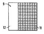
本発明によれば、センサ3の接触面9には電極マトリクスの電極だけでなく、付加的に超音波変換器も組み込まれ、該変換器のうち少なくとも1つは超音波を発信し、もう1つは超音波を受信する機能を持ち、これら変換器は種々異なる形態で配置される。図2は、該変換器の一例を斜視図で示す。図3〜8において、暗く陰影を付けた部分は電気インピーダンスを測定する電極領域であり、それ以外の部分は超音波測定のための超音波変換器が配置される空間を示す。このような組み合わせ測定法に対しては、その場合、超音波の組織への伝達と、電極と組織との良導電性の接触とを同じ手段、即ちゲル剤で確保するとよい。
【0011】
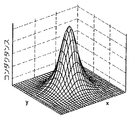
図9〜11はシミュレーション計算の結果を示し、これから超音波変換器を収納する空間を作るべく電極を間引いても、位置の解読能が僅かしか低下しないことが分かる。図10はシミュレーションしたコンダクタンス分布を、図9の全交点に細かく配置した電極マトリクスを持つ電気インピーダンスシステムで如何に測定したかを示す。図11は、電極を1/4だけ配置した、従って電極間に超音波変換器用のスペースが存在する場合のコンダクタンスの同様な分布を示す。シミュレーションした組織非均一性の信号は、図11と10で殆ど同一である。
【0012】
超音波変換器12は、電気インピーダンス測定用の電極と同様に、ケーブル4を介し両検査システムの電子機器を統合した電子機器5に接続されている。両検査の結果は同一モニタ6で表示され、このため画像融合時に両データレコードの登録の問題が著しく容易になる。これはまた、生検を行う際に、その病変部の位置決めを簡単化し、これにより感度、特異度共に上がる。
【0013】
1つの検査、即ち所見のための超音波検査と良性か悪性かを判別するインピーダンス測定において、作業流れの非常な改善ができる。同時にこの兼用検査装置は、その使用が容易でかつ良好であるばかりか、各1台の超音波装置と電気インピーダンス装置との合計より廉価でもある。勿論、各々唯一の診断だけを行い、他の診断は押し釦の操作により追加するようにしてもよい。本発明による電気インピーダンス測定と超音波検査の兼用装置のその他の適用領域としては甲状腺、リンパ節、血管、前立腺等の検査が挙げられる。
【図面の簡単な説明】
【図1】本発明のインピーダンス・スキャナによる胸部検査を模式的に示す。
【図2】電極マトリクス近傍に配置される超音波変換器を持つセンサを斜視図で示す。
【図3】図2によるセンサの接触面の平面を示す。
【図4】電極マトリクスと超音波変換器を備えたセンサ接触面の一例を示す。
【図5】電極マトリクスと超音波変換器を備えたセンサ接触面の他の例を示す。
【図6】電極マトリクスと超音波変換器を備えたセンサ接触面の他の例を示す。
【図7】電極マトリクスと超音波変換器を備えたセンサ接触面の他の例を示す。
【図8】電極マトリクスと超音波変換器を備えたセンサ接触面の他の例を示す。
【図9】電極マトリクスの網目を示す。
【図10】細かい電極分布で腫瘍の電気インピーダンスを測定した電流分布を示す。
【図11】粗い電極分布で腫瘍の電気インピーダンスを測定した電流分布を示す。
【符号の説明】
1 胸部
2 被検者
3 センサ
4 ケーブル
5 電子機器
6 モニタ
7 第二のケーブル
8 対向電極
9 接触面
10 腫瘍
11 電極マトリクス
12 超音波変換器[0001]
BACKGROUND OF THE INVENTION
The present invention comprises a sensor, electrical impedance scanner arranged an electrode matrix for detecting a surface distribution of the body current and / or body potential exits from the opposite electrode disposed on a part position of the subject's body on the contact surface About.
[0002]
[Prior art]
An impedance scanner of this kind is known from German Offenlegungsschrift 10 102 204. Since this malignant tumor has impedance characteristics different from those of healthy surrounding tissues, when a weak alternating voltage (5 V or less) is applied to the body through the counter electrode, or a weak alternating current (4 mA or less) is applied to the body. This is based on the finding that the electric field changes in the range of the tumor when passing through and the current density and potential distribution change accordingly on the skin surface under the sensor with the electrode matrix.
[0003]
For example, in the ultrasonic apparatus described in US Pat. No. 5,787,889, in order to display the results of such impedance measurement in more detail, the cyst is often first removed and biopsied, often in advance or subsequently. Perform an ultrasound examination to help locate the disorder. Ultrasonography itself is not very well specified to distinguish between normal and malignant disorders.
[0004]
The sequential execution of the different tests is not only time consuming, but also has the disadvantage of requiring more labor to relate each detected result, ie to compare the location of each detected fault.
[0005]
[Problems to be solved by the invention]
Accordingly, an object of the present invention is to configure an impedance scanner of the type mentioned at the beginning so that an ultrasonic inspection can be performed by a simple method and a simple relationship between measurement results.
[0006]
[Means for Solving the Problems]
In order to solve this problem, according to the present invention, an additional ultrasonic transducer that is connected to an ultrasonic inspection apparatus including a monitor on the contact surface of the sensor and transmits and receives ultrasonic waves is incorporated. In that case, the results of both inspection systems, i.e., the results of electrical impedance measurement and ultrasonic inspection, may be displayed on one monitor at the same time, so that the electronic equipment of both inspection systems may be integrated into one apparatus.
[0007]
In that case, the ultrasonic transducer is placed in the vicinity of the electrode matrix, or in order to further improve the image correlation of both inspection systems, in the absence of the electrode matrix of the sensor, for example according to the selection of the coarse electrode distribution Deploy.
[0008]
DETAILED DESCRIPTION OF THE INVENTION
Other advantages, features and details of the invention will become apparent from the following description of embodiments and reference to the drawings.
[0009]
FIG. 1 schematically shows a situation in which the chest 1 of a
[0010]
According to the invention, not only the electrodes of the electrode matrix but also an ultrasonic transducer is incorporated in the
[0011]
FIGS. 9 to 11 show the results of the simulation calculation, and it can be seen that even if the electrodes are thinned out to make a space for accommodating the ultrasonic transducer, the position deciphering ability is slightly lowered. FIG. 10 shows how the simulated conductance distribution was measured with an electrical impedance system having an electrode matrix finely arranged at all intersections of FIG. FIG. 11 shows a similar distribution of conductance when the electrodes are arranged by a quarter, so that there is space for the ultrasonic transducer between the electrodes. The simulated tissue non-uniformity signals are almost identical in FIGS.
[0012]
The
[0013]
The work flow can be greatly improved in one test, that is, an ultrasonic test for finding and impedance measurement for discriminating between benign and malignant. At the same time, this combined inspection device is easy and good to use, and is also cheaper than the total of one ultrasonic device and one electrical impedance device. Of course, only one diagnosis may be performed, and the other diagnosis may be added by operating a push button. Other application areas of the combined apparatus for electrical impedance measurement and ultrasonic examination according to the present invention include examination of thyroid gland, lymph node, blood vessel, prostate and the like.
[Brief description of the drawings]
FIG. 1 schematically illustrates a chest examination with an impedance scanner of the present invention.
FIG. 2 is a perspective view showing a sensor having an ultrasonic transducer disposed in the vicinity of an electrode matrix.
3 shows a plane of the contact surface of the sensor according to FIG.
FIG. 4 shows an example of a sensor contact surface including an electrode matrix and an ultrasonic transducer.
FIG. 5 shows another example of a sensor contact surface including an electrode matrix and an ultrasonic transducer.
FIG. 6 shows another example of a sensor contact surface including an electrode matrix and an ultrasonic transducer.
FIG. 7 shows another example of a sensor contact surface including an electrode matrix and an ultrasonic transducer.
FIG. 8 shows another example of a sensor contact surface including an electrode matrix and an ultrasonic transducer.
FIG. 9 shows a mesh of an electrode matrix.
FIG. 10 shows a current distribution obtained by measuring the electrical impedance of a tumor with a fine electrode distribution.
FIG. 11 shows a current distribution obtained by measuring the electrical impedance of a tumor with a rough electrode distribution.
[Explanation of symbols]
DESCRIPTION OF SYMBOLS 1
Claims (5)
Applications Claiming Priority (2)
| Application Number | Priority Date | Filing Date | Title |
|---|---|---|---|
| DE10136529A DE10136529C1 (en) | 2001-07-26 | 2001-07-26 | Electrical impedance and ultrasound scanner for detecting surface distribution of body currents/voltage has a probe with an electrode matrix on its contact surface |
| DE10136529.2 | 2001-07-26 |
Publications (2)
| Publication Number | Publication Date |
|---|---|
| JP2003093365A JP2003093365A (en) | 2003-04-02 |
| JP4409155B2 true JP4409155B2 (en) | 2010-02-03 |
Family
ID=7693241
Family Applications (1)
| Application Number | Title | Priority Date | Filing Date |
|---|---|---|---|
| JP2002213389A Expired - Fee Related JP4409155B2 (en) | 2001-07-26 | 2002-07-23 | Ultrasonic inspection and electrical impedance scanner |
Country Status (4)
| Country | Link |
|---|---|
| US (1) | US6952606B2 (en) |
| JP (1) | JP4409155B2 (en) |
| DE (1) | DE10136529C1 (en) |
| IL (1) | IL150529A (en) |
Families Citing this family (21)
| Publication number | Priority date | Publication date | Assignee | Title |
|---|---|---|---|---|
| JP2004528935A (en) * | 2001-06-13 | 2004-09-24 | シーケーエム ダイアグノスティックス,インコーポレーテッド | Non-invasive detection method and detection device for tissue |
| AU2003219492A1 (en) * | 2002-04-04 | 2003-10-20 | Transscan Medical Ltd. | Breast classification based on impedance measurements |
| JP2004305435A (en) * | 2003-04-07 | 2004-11-04 | Aloka Co Ltd | Ultrasonic diagnostic apparatus |
| JP2005270375A (en) * | 2004-03-25 | 2005-10-06 | Ge Medical Systems Global Technology Co Llc | Ultrasonic probe and attachment |
| US7865236B2 (en) * | 2004-10-20 | 2011-01-04 | Nervonix, Inc. | Active electrode, bio-impedance based, tissue discrimination system and methods of use |
| US20060085048A1 (en) * | 2004-10-20 | 2006-04-20 | Nervonix, Inc. | Algorithms for an active electrode, bioimpedance-based tissue discrimination system |
| US20070258896A1 (en) * | 2006-05-02 | 2007-11-08 | Mirabel Medical Systems Ltd. | Contrast Agents In Medical Imaging |
| FR2906612B1 (en) * | 2006-09-28 | 2009-03-06 | Centre Nat Rech Scient | METHOD AND DEVICE FOR TOMOGRAPHY BY ELECTRIC IMPEDANCE. |
| DE102007002755A1 (en) * | 2007-01-18 | 2008-07-24 | Aesculap Ag & Co. Kg | Method and device for the non-invasive examination of a body with ultrasound radiation |
| US8886291B2 (en) * | 2008-01-09 | 2014-11-11 | The Trustees Of Dartmouth College | Systems and methods for combined ultrasound and electrical impedance imaging |
| AT506293B1 (en) * | 2008-07-16 | 2009-08-15 | Univ Innsbruck | METHOD OF ILLUSTRATING AN OBJECT AND DEVICE FOR CARRYING OUT THE METHOD |
| DE102008039844A1 (en) * | 2008-08-27 | 2010-03-04 | Fresenius Medical Care Deutschland Gmbh | Probe with at least two electrodes for impedance measurement, arrangement and method for this purpose |
| WO2011022068A1 (en) * | 2009-08-21 | 2011-02-24 | Rutkove Seward B | A hand-held device for electrical impedance myography |
| GB0920388D0 (en) * | 2009-11-20 | 2010-01-06 | Wzvi Ltd | Electrical impedance detection and ultrasound scanning of body tissue |
| GB201020729D0 (en) * | 2010-12-07 | 2011-01-19 | Univ Sussex The | Electrical impedance detection and ultrasound scanning of body tissue |
| US9693752B2 (en) * | 2011-06-21 | 2017-07-04 | Rescon Ltd | Non-resistive contact electrosonic sensor systems |
| WO2013124735A1 (en) | 2012-02-22 | 2013-08-29 | Rescon Ltd | Non-resistive contact electrical systems and methods for visualizing the structure and function of objects or systems |
| US20140125358A1 (en) | 2012-07-13 | 2014-05-08 | Rescon Ltd | Reducing movement and electrostatic interference in a non-resistive contact sensor assembly |
| US9277887B2 (en) | 2013-02-01 | 2016-03-08 | Rescon Ltd | Signal stabilization in a dielectric sensor assembly |
| US9239347B2 (en) | 2012-08-31 | 2016-01-19 | Rescon Ltd | Signal stabilization in a non-resistive contact sensor assembly |
| FR3008806B1 (en) * | 2013-07-22 | 2017-07-07 | Centre Nat De La Rech Scient - Cnrs - | METHOD AND DEVICE FOR ACOUSTOELECTRIC IMAGING |
Family Cites Families (7)
| Publication number | Priority date | Publication date | Assignee | Title |
|---|---|---|---|---|
| US6678552B2 (en) * | 1994-10-24 | 2004-01-13 | Transscan Medical Ltd. | Tissue characterization based on impedance images and on impedance measurements |
| US6560480B1 (en) * | 1994-10-24 | 2003-05-06 | Transscan Medical Ltd. | Localization of anomalies in tissue and guidance of invasive tools based on impedance imaging |
| US5787889A (en) * | 1996-12-18 | 1998-08-04 | University Of Washington | Ultrasound imaging with real time 3D image reconstruction and visualization |
| US5935066A (en) * | 1997-02-27 | 1999-08-10 | Vanderbilt University | System and method for measuring of lung vascular injury by ultrasonic velocity and blood impedance |
| IL150623A0 (en) * | 2000-01-18 | 2003-02-12 | Siemens Ag | Measurement system for examining a section of tissue on a patient and the use of a measurement system of this type |
| US6725087B1 (en) * | 2000-09-19 | 2004-04-20 | Telectroscan, Inc. | Method and apparatus for remote imaging of biological tissue by electrical impedance tomography through a communications network |
| US6807444B2 (en) * | 2001-11-05 | 2004-10-19 | Hosheng Tu | Apparatus and methods for monitoring tissue impedance |
-
2001
- 2001-07-26 DE DE10136529A patent/DE10136529C1/en not_active Expired - Fee Related
-
2002
- 2002-07-02 IL IL150529A patent/IL150529A/en not_active IP Right Cessation
- 2002-07-23 JP JP2002213389A patent/JP4409155B2/en not_active Expired - Fee Related
- 2002-07-26 US US10/202,871 patent/US6952606B2/en not_active Expired - Lifetime
Also Published As
| Publication number | Publication date |
|---|---|
| IL150529A0 (en) | 2003-02-12 |
| DE10136529C1 (en) | 2002-12-12 |
| US20030028092A1 (en) | 2003-02-06 |
| US6952606B2 (en) | 2005-10-04 |
| JP2003093365A (en) | 2003-04-02 |
| IL150529A (en) | 2007-03-08 |
Similar Documents
| Publication | Publication Date | Title |
|---|---|---|
| JP4409155B2 (en) | Ultrasonic inspection and electrical impedance scanner | |
| US8417328B2 (en) | Electrical systems for detection and characterization of abnormal tissue and cells | |
| US8886291B2 (en) | Systems and methods for combined ultrasound and electrical impedance imaging | |
| US7302292B2 (en) | Breast cancer screening | |
| US7409243B2 (en) | Breast cancer detection | |
| US10898100B2 (en) | Electrical impedance myography | |
| EP0955890B1 (en) | Device for imaging the prostata | |
| EP1289414B1 (en) | Combined impedance imaging and mammography | |
| JPH10512462A (en) | Impedance imaging device and multi-element probe | |
| US9066671B2 (en) | System and method for early breast cancer detection using electrical property enhanced tomography | |
| Wan et al. | Sensitivity study of an ultrasound coupled transrectal electrical impedance tomography system for prostate imaging | |
| KR100688355B1 (en) | Apparatus and method for detecting lesions in the body | |
| EP3651641A1 (en) | System for measuring the electrical impedance in human tissues | |
| JPH0824259A (en) | Needle ultrasonic probe | |
| KR19990041734A (en) | Ultrasound 3D Imaging and Breast Cancer Screening Method | |
| EA012006B1 (en) | Electroimpedance computer mammograph | |
| Malich et al. | Electrical impedance scanning-A new diagnostic tool in cancer detection: Current status and recent developments | |
| RU97108159A (en) | IMPEDANCE VISUALIZATION DEVICE AND MULTI-ELEMENT PROBE | |
| WO2007081231A2 (en) | A probe for searching neoplastic tissues and a technique for localization of neoplastic lesions |
Legal Events
| Date | Code | Title | Description |
|---|---|---|---|
| A621 | Written request for application examination |
Free format text: JAPANESE INTERMEDIATE CODE: A621 Effective date: 20050713 |
|
| A131 | Notification of reasons for refusal |
Free format text: JAPANESE INTERMEDIATE CODE: A131 Effective date: 20080821 |
|
| A521 | Request for written amendment filed |
Free format text: JAPANESE INTERMEDIATE CODE: A523 Effective date: 20081113 |
|
| A131 | Notification of reasons for refusal |
Free format text: JAPANESE INTERMEDIATE CODE: A131 Effective date: 20090602 |
|
| A521 | Request for written amendment filed |
Free format text: JAPANESE INTERMEDIATE CODE: A523 Effective date: 20090901 |
|
| RD03 | Notification of appointment of power of attorney |
Free format text: JAPANESE INTERMEDIATE CODE: A7423 Effective date: 20090901 |
|
| TRDD | Decision of grant or rejection written | ||
| A01 | Written decision to grant a patent or to grant a registration (utility model) |
Free format text: JAPANESE INTERMEDIATE CODE: A01 Effective date: 20091013 |
|
| A01 | Written decision to grant a patent or to grant a registration (utility model) |
Free format text: JAPANESE INTERMEDIATE CODE: A01 |
|
| A61 | First payment of annual fees (during grant procedure) |
Free format text: JAPANESE INTERMEDIATE CODE: A61 Effective date: 20091111 |
|
| R150 | Certificate of patent or registration of utility model |
Ref document number: 4409155 Country of ref document: JP Free format text: JAPANESE INTERMEDIATE CODE: R150 Free format text: JAPANESE INTERMEDIATE CODE: R150 |
|
| FPAY | Renewal fee payment (event date is renewal date of database) |
Free format text: PAYMENT UNTIL: 20121120 Year of fee payment: 3 |
|
| FPAY | Renewal fee payment (event date is renewal date of database) |
Free format text: PAYMENT UNTIL: 20121120 Year of fee payment: 3 |
|
| FPAY | Renewal fee payment (event date is renewal date of database) |
Free format text: PAYMENT UNTIL: 20131120 Year of fee payment: 4 |
|
| R250 | Receipt of annual fees |
Free format text: JAPANESE INTERMEDIATE CODE: R250 |
|
| R250 | Receipt of annual fees |
Free format text: JAPANESE INTERMEDIATE CODE: R250 |
|
| R250 | Receipt of annual fees |
Free format text: JAPANESE INTERMEDIATE CODE: R250 |
|
| R250 | Receipt of annual fees |
Free format text: JAPANESE INTERMEDIATE CODE: R250 |
|
| R250 | Receipt of annual fees |
Free format text: JAPANESE INTERMEDIATE CODE: R250 |
|
| R250 | Receipt of annual fees |
Free format text: JAPANESE INTERMEDIATE CODE: R250 |
|
| R250 | Receipt of annual fees |
Free format text: JAPANESE INTERMEDIATE CODE: R250 |
|
| R250 | Receipt of annual fees |
Free format text: JAPANESE INTERMEDIATE CODE: R250 |
|
| LAPS | Cancellation because of no payment of annual fees |