JP4408564B2 - Device for holding timber pieces - Google Patents
Device for holding timber pieces Download PDFInfo
- Publication number
- JP4408564B2 JP4408564B2 JP2000545686A JP2000545686A JP4408564B2 JP 4408564 B2 JP4408564 B2 JP 4408564B2 JP 2000545686 A JP2000545686 A JP 2000545686A JP 2000545686 A JP2000545686 A JP 2000545686A JP 4408564 B2 JP4408564 B2 JP 4408564B2
- Authority
- JP
- Japan
- Prior art keywords
- pendulum
- frame
- spike
- timber
- pin
- Prior art date
- Legal status (The legal status is an assumption and is not a legal conclusion. Google has not performed a legal analysis and makes no representation as to the accuracy of the status listed.)
- Expired - Fee Related
Links
Images

Classifications
-
- B—PERFORMING OPERATIONS; TRANSPORTING
- B27—WORKING OR PRESERVING WOOD OR SIMILAR MATERIAL; NAILING OR STAPLING MACHINES IN GENERAL
- B27B—SAWS FOR WOOD OR SIMILAR MATERIAL; COMPONENTS OR ACCESSORIES THEREFOR
- B27B17/00—Chain saws; Equipment therefor
- B27B17/0041—Saw benches or saw bucks
- B27B17/0075—Saw benches or saw bucks the workpiece being held in a cantilever manner
Landscapes
- Life Sciences & Earth Sciences (AREA)
- Engineering & Computer Science (AREA)
- Mechanical Engineering (AREA)
- Wood Science & Technology (AREA)
- Forests & Forestry (AREA)
- Chemical And Physical Treatments For Wood And The Like (AREA)
- Manipulator (AREA)
- Manufacture Of Wood Veneers (AREA)
- Gripping Jigs, Holding Jigs, And Positioning Jigs (AREA)
- Ladders (AREA)
Abstract
Description
【0001】
(技術分野)
本発明は、適切な切断装置で切断するときに材木片を保持するための装置に関する。この切断装置は通常、のこぎり、例えばチェーンソーから成る。
【0002】
傷害の危険性をできるだけ少なくして適切な作業高さでチェーンソーにより切断するために、丸太、曲がった枝、ノンリターンパレット、および類似物など、様々な種類の材木を保持できることが望ましい。一般的に切断は、材木が地面に横たわるか、または目的に適さない他の装置内に置かれた状態で行われ、これは人的傷害や工具破損の大きな危険性を伴う。したがって、様々な長さ、厚さ、および形状の材木を簡単かつ安全な方法で保持するための装置がおおいに必要である。
【0003】
(従来技術)
米国特許4,718,652から、上記請求項1の前文による装置はすでに知られている。この既知の装置では、振り子は、その枢動性にもかかわらず、実際には、幾つかの予め定められた枢動位置のうち、振り子の構造によって、かつ次いで主として振り子のスパイクの配置によって決定される1つを取る。これは、既知の装置によって保持された材木片の向きがかなり変化することを暗示する。別の言葉で表現すると、実際には材木片の傾きが、木材片の直径によって、かつ振り子のスパイクのうちどれが現在材木片と係合しているかによって異なってくる。上記米国特許によると、スパイクはつまり、振り子の枢軸に対して本質的に直角に伸長して、一列に配置される。
【0004】
(発明の開示)
本発明の目的は、装置の使用者が便利に木材片をその中に挿入して、これらの材木片に所望する位置または向きを取らせることができるという意味で、木材片を受容し保持する装置の能力が改善されるように、請求項1の前文に記載する具体化(Shaping)をさらに発展させることである。
【0005】
提示した目的は、本発明によれば、装置を上記請求項1の特徴に従って設計することで達成される。フレームの下部の上向きのスパイクに対して相対的に無段変動位置を取るように配置されたスパイクを持つ振り子の結果、装置の使用者は、材木片の直径または形状に関係なく、装置における材木片の希望の位置および向き、例えば材木片の水平位置を常に得ることができる。
【0006】
本発明の好適な実施形態によれば、自由に枢動する振り子は、振り子の枢軸とそのスパイクとの間のその長さに関し、調整することができる。例えば、一そろいの特定の厚さの材木片のために、この長さを減少することができる。
【0007】
別の好適な実施形態によれば、振り子は、より厚い材木片のために、水平面より上に持ち上げることによって上向きに可動であり、それによってそれが固定ショルダから離脱され、その後振り子のより下の穴に再装着するために側方に動かすことができる。
【0008】
材木片の取扱いに関して最大限の平易さを達成するために、フレームは、材木片を開口側から側方に挿入することを可能にするよう、片側に向かって開口状態に形成することが好ましい。そのような側方の挿入中に、振り子は手動的に、または材木片からの作用により遠ざけることができ、または次いで、例えば上述の固定ショルダ上に振り子を載せることによって、振り子を起立状態にすることができる。
【0009】
さらに、振り子は基本的に、スパイクが設けられた基部と、各々に振り子の枢着を構成するだぼまたはピンを受容するための穴が設けられた脚部とを備えたU字形であることが好ましい。
【0010】
本発明のさらなる実施形態によると、振り子およびフレーム上部の両方のスパイクは、基本的に振り子の枢軸に沿った方向に一列に配置する。
【0011】
本発明による装置のさらなる特徴およびそれに関連する利点は、独立請求項および以下の説明から明らかになるであろう。
【0012】
添付の図面に関連して、例として挙げる本発明の実施形態のより厳密な説明を以下に続ける。
【0013】
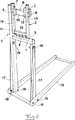
図1の線図において、1は一般的に9で表わされるフレームの下部を表わし、2は振り子自体を表わし、3はフレームの下部1に配置されたスパイクを表わす。振り子2に配置されたスパイクは4で表わし、5は固定ショルダを表わす。振り子の穴は6で表わし、7はだぼまたはピンを表わす。これらは、振り子の穴6に受容されるように構成される。8は、フレーム9の上部を表わす。
【0014】
スパイク4付きの振り子2は、フレームの下部のスパイク3に対して相対的に無段変動位置を取るように構成される。振り子2は自由に枢動するので、その自重によって、振り子の回転範囲内でそのスパイク4により材木片に係合してそれを保持する。
【0015】
振り子2は、より厚い材木片のために、水平面より上に持ち上げることによって上向きに可動であり、それによって振り子は固定ショルダ5から離脱され、その後振り子のより下の穴6に再装着するために側方に動かすことができる。その結果として、振り子は、それぞれこれらと係合したり離脱するように、だぼまたはピン7に沿って側方に可動である。固定ショルダ5は、だぼまたはピン7上に振り子を維持するように構成されるが、すでに上述した通り、振り子が固定ショルダ5を通過できるように上に持ち上げられたとき、振り子はだぼまたはピン7との係合を離脱させることができる。
【0016】
振り子のスパイク4とフレーム下部1のスパイク3の合同作用の結果、様々な材木片を材木片自体の重さによって、張り出し状態に保持することができる。
【0017】
材木片の一端を正面からフレーム内に挿入することができ、それにより振り子は、材木の厚さに自由に順応させるために後方に押される。材木片が希望の高さについてから釈放したとき、振り子の下側のスパイク4が材木片の上側に貫入している場合、張り出し重さのために、フレームの下部1のスパイク3は材木片が滑り離れることを防止する。上記ですでに指摘した通り、振り子を異なる間隔で作動させるため、振り子の高さはフレームの上部8のその固定点を変更することができる。
【0018】
装置に保持された材木片は、最後の切刃まで自由に切断することができる。
【0019】
フレーム9は、材木片を開口側から側方に挿入することを可能にするために、片側の方向に開口した形状である。使用者はそれにより、最も便利な方法で装置に材木片を配置する最大限の自由を得る。
【0020】
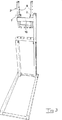
図2−5は、図1を利用して説明した装置の原理を以下の実現できるかの例を示す。図2−5では、対応する構成部品については、できるだけ図1と同じ参照符号を使用するが、特定の細部については、さらなる参照符号が追加された。図2と3を比較すると、異なる穴を備えた振り子2が、フレームの上部8に設けられただぼまたはピン7と係合することが明白である。ここでフレーム上部8という表現の範囲内に含まれるのは、フレーム9の基本的に垂直なサイドビーム11に取り付けられた基本的に水平なビーム10だけでなく、ビーム11の最上部も含まれる。より厳密には、ピン7の1つはビーム11の上部に取り付けられ、ピン7の残りはビーム部12に取り付けられ、次にビーム部12が水平ビーム11に取り付けられる。したがって、その瞬間ピンが係合する振り子の穴6と合同作用するピン7は、振り子の枢着を構成する。振り子は、ピンと振り子の穴との間でそれぞれ係合したり離脱するように、ピンに沿って可動である。振り子の特定の位置にある前述の固定ショルダ5は、そのような運動の制限体として働く。さらに厳密には、振り子がその通常の自由枢動機能モードのときに、固定ショルダ5は、振り子がピン7から外に押し出されるのを防止する。しかし、振り子2は、図4に示す位置に起立させることができ、そこで振り子は起立状態で固定ショルダ5上で静止させることができ、または振り子がピン7との係合を離脱し、かつ振り子がこれらのピンから外れるように、さらに側方に動かすことができる。
【0021】
振り子は基本的に、スパイク4を設けた基部13と、ピン7を受容するための1組の穴6を各々に設けた脚部14とを備えたU字形である。
【0022】
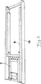
フレームの片側に設けたビーム11は、片面にスパイク3が設けられたフレーム下部1を通過して伸長するが、この伸長部は、フレーム下部1の他端に対応物が無いので、図4に特に明瞭に示す開口がそこに残される。この側部開口は、木材片を装置の片側から振り子とフレーム下部1のスパイク3との間の位置に挿入することを可能にする。したがって、材木片を長さ方向に動かすことでしか装置内に挿入することができないという意味の制限が無い。
【0023】
フレーム9は、下層で支持するように意図された一般的に15で表わすベースフレームに枢動可能に接続される。そのような枢動性を可能にするこの接続は、16で表わされる。フレーム9は、それがベースフレームから起立した図2−4に示す位置から、それがベースフレーム15に向かって折り畳まれた図5に示す位置までの間で、ベースフレーム15に対して枢動可能である。フレーム9をその起立位置に固定するために、釈放可能な手段17を設ける。これらの手段は、図2−4に示すように、ベースフレーム15に対する点18とフレーム9に対する点19との間で作動するかんぬきの性質を有する。
【0024】
フレーム9はその振り子2と一緒に、図5から分かるように、基本的にベースフレーム内の位置に折り畳むことができ、その結果、装置は最小限の所用空間で容易に輸送し、保管することができる。
【0025】
かんぬき17はベースフレーム15に枢結し、フレーム9およびかんぬき17の両方をベースフレーム15内の折り畳むことができるように、図に示すように例えば蝶ナットを利用して、フレーム9に対してその固定点19で釈放可能であることが好ましい。
【0026】
図1にある通り、それぞれフレーム下部1および振り子2のスパイク3および4は、基本的に相互に平行な、かつ、さらに基本的に振り子2の枢軸に沿って伸長する、一列に配置される。これは、スパイク3、4の列が、装置内に配置された材木片の長さ方向に基本的に交差することを暗示する。スパイクのそのような配置により、装置内で材木片を常時、基本的に水平位置に効果的に保持することができる。
【0027】
上述の実施形態は、発明の着想を例示するのに役立つだけである。ひとたびこれが提示されると、言うまでも無く当業者は、上記請求の範囲で意図する保護の範囲から逸脱することなく、細部の調整を実行し、等価の解決法を提示することができる。
【図面の簡単な説明】
【図1】 一本の材木が装置に保持されている状態にある、後方から斜めに見た本発明による装置の実施形態を原則的に純粋に示す斜視図。
【図2】 本発明のより詳細な実施形態の主として図1と同一方向からの材木を除いた斜視図。
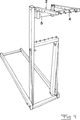
【図3】 別の方向から見た、振り子が起立した状態の図2による装置の斜視図。
【図4】 振り子を上方に枢動して固定ショルダ上で静止するように転位させた状態の図2による装置を示す別の角度からの斜視図。
【図5】 折り畳まれた状態にある、図2による装置の斜視図。[0001]
(Technical field)
The present invention relates to a device for holding a piece of timber when cutting with a suitable cutting device. This cutting device usually consists of a saw, for example a chainsaw.
[0002]
It is desirable to be able to hold various types of timber, such as logs, bent branches, non-return pallets, and the like, in order to reduce the risk of injury as much as possible and cut with a chainsaw at an appropriate working height. Cutting is generally done with the timber lying on the ground or placed in other equipment that is not suitable for the purpose, which carries a great risk of personal injury and tool breakage. Therefore, there is a great need for a device for holding timbers of various lengths, thicknesses and shapes in a simple and safe manner.
[0003]
(Conventional technology)
From U.S. Pat. No. 4,718,652, a device according to the preamble of claim 1 is already known. In this known device, the pendulum is actually determined, among its several pivotal positions, by the structure of the pendulum and then mainly by the placement of the pendulum spikes, despite its pivotability. Take one to be. This implies that the orientation of the timber pieces held by the known device changes considerably. In other words, the tilt of the timber actually depends on the diameter of the timber and which of the pendulum spikes is currently engaged with the timber. According to said US patent, the spikes are thus arranged in a row, extending essentially perpendicular to the pivot axis of the pendulum.
[0004]
(Disclosure of the Invention)
It is an object of the present invention to receive and hold a piece of wood in the sense that the user of the device can conveniently insert the piece of wood into it and have these timber pieces take the desired position or orientation. It is to further develop the shaping described in the preamble of claim 1 so that the capabilities of the device are improved.
[0005]
The object presented is achieved according to the invention by designing the device according to the features of claim 1 above. As a result of the pendulum with the spikes arranged to take a stepless relative position relative to the upward spikes at the bottom of the frame, the user of the device will be able to It is always possible to obtain the desired position and orientation of the pieces, for example the horizontal position of the timber pieces.
[0006]
According to a preferred embodiment of the present invention, the freely pivoting pendulum can be adjusted with respect to its length between the pendulum pivot and its spike. For example, this length can be reduced for a set of specific pieces of timber.
[0007]
According to another preferred embodiment, the pendulum is movable upward by lifting it above the horizontal plane due to the thicker piece of wood, so that it is detached from the fixed shoulder and then below the pendulum. Can be moved laterally to refit the hole.
[0008]
In order to achieve maximum simplicity with respect to the handling of the timber pieces, the frame is preferably formed in an open state towards one side so as to allow the timber pieces to be inserted laterally from the open side. During such lateral insertion, the pendulum can be moved away manually or by action from a piece of timber, or then the pendulum is brought upright, for example by placing the pendulum on a fixed shoulder as described above be able to.
[0009]
In addition, the pendulum is essentially U-shaped with a base provided with spikes and a leg provided with a hole for receiving a dowel or pin each comprising a pivot attachment of the pendulum. Is preferred.
[0010]
According to a further embodiment of the invention, the spikes on both the pendulum and the upper part of the frame are arranged in a row essentially in a direction along the pivot axis of the pendulum.
[0011]
Further features of the device according to the invention and the advantages associated therewith will become apparent from the independent claims and the following description.
[0012]
A more rigorous description of embodiments of the present invention, given by way of example, continues below with reference to the accompanying drawings.
[0013]
In the diagram of FIG. 1, 1 represents the lower part of the frame, generally denoted by 9, 2 represents the pendulum itself, and 3 represents the spike located in the lower part 1 of the frame. A spike placed on the
[0014]
The
[0015]
The
[0016]
As a result of the combined action of the
[0017]
One end of the timber piece can be inserted into the frame from the front, whereby the pendulum is pushed backward to freely adjust to the thickness of the timber. When the timber piece is released from the desired height, if the
[0018]
The piece of timber held in the device can be cut freely until the last cutting edge.
[0019]
The
[0020]
FIG. 2-5 shows an example of whether the principle of the apparatus described with reference to FIG. 1 can be realized as follows. In FIGS. 2-5, the same reference numerals as in FIG. 1 are used for corresponding components as much as possible, but additional reference numerals have been added for specific details. Comparing FIGS. 2 and 3, it is clear that the
[0021]
The pendulum is basically U-shaped with a base 13 provided with
[0022]
The
[0023]
The
[0024]
The
[0025]
The
[0026]
As shown in FIG. 1, the
[0027]
The above-described embodiments only serve to illustrate the inventive idea. Once this has been presented, it will be appreciated that those skilled in the art can make minor adjustments and provide equivalent solutions without departing from the intended scope of protection in the claims.
[Brief description of the drawings]
FIG. 1 is a perspective view, in principle, purely showing an embodiment of the device according to the invention, seen obliquely from the rear, with a piece of timber being held by the device.
FIG. 2 is a perspective view of a more detailed embodiment of the present invention, excluding timbers mainly from the same direction as FIG.
3 is a perspective view of the device according to FIG. 2 with the pendulum upright, as seen from another direction.
4 is a perspective view from another angle showing the device according to FIG. 2 with the pendulum pivoted upwards and displaced to rest on a stationary shoulder. FIG.
FIG. 5 is a perspective view of the device according to FIG. 2 in a folded state.
Claims (11)
Applications Claiming Priority (3)
| Application Number | Priority Date | Filing Date | Title |
|---|---|---|---|
| SE9801297A SE517581C2 (en) | 1998-04-15 | 1998-04-15 | Device for cutting wood |
| SE9801297-4 | 1998-04-15 | ||
| PCT/SE1999/000601 WO1999055504A1 (en) | 1998-04-15 | 1999-04-15 | A device for holding pieces of wood |
Publications (2)
| Publication Number | Publication Date |
|---|---|
| JP2002512902A JP2002512902A (en) | 2002-05-08 |
| JP4408564B2 true JP4408564B2 (en) | 2010-02-03 |
Family
ID=20410954
Family Applications (1)
| Application Number | Title | Priority Date | Filing Date |
|---|---|---|---|
| JP2000545686A Expired - Fee Related JP4408564B2 (en) | 1998-04-15 | 1999-04-15 | Device for holding timber pieces |
Country Status (10)
| Country | Link |
|---|---|
| US (1) | US6322064B1 (en) |
| EP (1) | EP1085966B1 (en) |
| JP (1) | JP4408564B2 (en) |
| AT (1) | ATE310616T1 (en) |
| AU (1) | AU4177399A (en) |
| DE (1) | DE69928526T2 (en) |
| PL (1) | PL189974B1 (en) |
| RU (1) | RU2258603C2 (en) |
| SE (1) | SE517581C2 (en) |
| WO (1) | WO1999055504A1 (en) |
Families Citing this family (10)
| Publication number | Priority date | Publication date | Assignee | Title |
|---|---|---|---|---|
| AUPQ322799A0 (en) * | 1999-10-01 | 1999-10-28 | Ray, Stafford James | Workholding jaw |
| US20090321603A1 (en) * | 2007-08-10 | 2009-12-31 | Krauth Rodney A | Support structure for cuttable elements |
| US8616540B2 (en) * | 2008-11-17 | 2013-12-31 | Tie Boss Llc | Trailer hitch attachment |
| DK2504134T3 (en) * | 2009-11-25 | 2017-04-10 | Wood Eng Tech Ltd | Process for drying timber products |
| GB201018700D0 (en) | 2010-11-05 | 2010-12-22 | Forest Master Ltd | Log holder and log holder assembly |
| US9375834B2 (en) * | 2011-04-06 | 2016-06-28 | Glebe Fabrications Limited | Sawhorse |
| JP5575063B2 (en) * | 2011-06-22 | 2014-08-20 | アイダエンジニアリング株式会社 | Work holding device replacement support device |
| GB201209007D0 (en) * | 2012-05-22 | 2012-07-04 | Forest Master Ltd | Log holder |
| CA2800791C (en) * | 2012-12-24 | 2014-05-20 | Norwood Industries Inc. | Pivot ratcheting log dog |
| US12329074B1 (en) * | 2023-01-31 | 2025-06-17 | Chad Martin | Wood tensioning apparatus for vegetation management educational training |
Family Cites Families (11)
| Publication number | Priority date | Publication date | Assignee | Title |
|---|---|---|---|---|
| US654134A (en) * | 1900-05-17 | 1900-07-24 | Abner G Clark | Sawbuck. |
| US4121814A (en) * | 1978-01-30 | 1978-10-24 | Prior Herbert E | Sawbuck |
| US4241772A (en) * | 1978-08-23 | 1980-12-30 | Scherer Fred F | Sawbuck |
| GB2098922B (en) * | 1981-05-26 | 1985-03-20 | Vaizey Geoffrey Stuart | Device for holding logs for sawing |
| US4448891A (en) * | 1982-09-28 | 1984-05-15 | Exxon Research & Engineering Co. | Zeolite L catalyst for reforming |
| US4641822A (en) | 1985-04-19 | 1987-02-10 | Fenerty Stanley W | Wood holder |
| NO157968C (en) * | 1986-02-14 | 1988-06-22 | Leif Brataas | Saw Horses. |
| US4718652A (en) * | 1986-05-30 | 1988-01-12 | Liebenstein Lowell G | Sawbuck |
| GB8812549D0 (en) * | 1988-05-26 | 1988-06-29 | Campbell N J | Log holding trestle |
| US4993686A (en) * | 1988-11-21 | 1991-02-19 | Diaz Eusebio M | Transmission work station |
| US5632475A (en) * | 1995-03-02 | 1997-05-27 | Mccanse Engineering Incorporated | Work holding apparatus |
-
1998
- 1998-04-15 SE SE9801297A patent/SE517581C2/en unknown
-
1999
- 1999-04-15 WO PCT/SE1999/000601 patent/WO1999055504A1/en not_active Ceased
- 1999-04-15 DE DE69928526T patent/DE69928526T2/en not_active Expired - Lifetime
- 1999-04-15 US US09/673,219 patent/US6322064B1/en not_active Expired - Lifetime
- 1999-04-15 AU AU41773/99A patent/AU4177399A/en not_active Abandoned
- 1999-04-15 EP EP99925512A patent/EP1085966B1/en not_active Expired - Lifetime
- 1999-04-15 JP JP2000545686A patent/JP4408564B2/en not_active Expired - Fee Related
- 1999-04-15 RU RU2000128640/12A patent/RU2258603C2/en not_active IP Right Cessation
- 1999-04-15 AT AT99925512T patent/ATE310616T1/en active
- 1999-04-15 PL PL99343410A patent/PL189974B1/en unknown
Also Published As
| Publication number | Publication date |
|---|---|
| JP2002512902A (en) | 2002-05-08 |
| EP1085966B1 (en) | 2005-11-23 |
| AU4177399A (en) | 1999-11-16 |
| PL189974B1 (en) | 2005-10-31 |
| PL343410A1 (en) | 2001-08-13 |
| SE517581C2 (en) | 2002-06-25 |
| EP1085966A1 (en) | 2001-03-28 |
| WO1999055504A1 (en) | 1999-11-04 |
| DE69928526T2 (en) | 2006-08-10 |
| RU2258603C2 (en) | 2005-08-20 |
| US6322064B1 (en) | 2001-11-27 |
| ATE310616T1 (en) | 2005-12-15 |
| SE9801297D0 (en) | 1998-04-15 |
| DE69928526D1 (en) | 2005-12-29 |
| SE9801297L (en) | 1999-10-16 |
Similar Documents
| Publication | Publication Date | Title |
|---|---|---|
| JP4408564B2 (en) | Device for holding timber pieces | |
| US4159821A (en) | Collapsible dual-height workbench | |
| US4641822A (en) | Wood holder | |
| US20050217446A1 (en) | Support table for a table saw | |
| EP2332706A1 (en) | Log Rest | |
| US8517067B2 (en) | Foldable chain saw workbench | |
| JPS5912282B2 (en) | Height adjustment device for folding tables, chairs, seats, etc. | |
| US6453958B1 (en) | Log splitting device | |
| US4535980A (en) | Log holder for use in splitting logs | |
| CN112293203A (en) | Forestry fir felling directional dumping auxiliary device | |
| EP2694255B1 (en) | A sawhorse | |
| US2733895A (en) | trenkle | |
| US20140360332A1 (en) | Saw bench | |
| CA1278982C (en) | Sawbuck | |
| US3985204A (en) | Tree stand | |
| EP2852478B1 (en) | Log holder | |
| US6073528A (en) | Chain saw jig | |
| US4850409A (en) | Felling saw and method of operating | |
| CA2816606A1 (en) | Log holder and log holder assembly | |
| WO2009070680A1 (en) | Sheet positioning device for table saw | |
| CN118575722B (en) | Directional device of cutting of trees | |
| GB2063154A (en) | Saw Bench | |
| CA2349589C (en) | Log splitting device | |
| EP0273886A1 (en) | Felling bar with support bracket | |
| US1407651A (en) | Lumber-jack s |
Legal Events
| Date | Code | Title | Description |
|---|---|---|---|
| A621 | Written request for application examination |
Free format text: JAPANESE INTERMEDIATE CODE: A621 Effective date: 20060203 |
|
| A131 | Notification of reasons for refusal |
Free format text: JAPANESE INTERMEDIATE CODE: A131 Effective date: 20090331 |
|
| A601 | Written request for extension of time |
Free format text: JAPANESE INTERMEDIATE CODE: A601 Effective date: 20090630 |
|
| A602 | Written permission of extension of time |
Free format text: JAPANESE INTERMEDIATE CODE: A602 Effective date: 20090707 |
|
| A601 | Written request for extension of time |
Free format text: JAPANESE INTERMEDIATE CODE: A601 Effective date: 20090730 |
|
| A602 | Written permission of extension of time |
Free format text: JAPANESE INTERMEDIATE CODE: A602 Effective date: 20090806 |
|
| A601 | Written request for extension of time |
Free format text: JAPANESE INTERMEDIATE CODE: A601 Effective date: 20090827 |
|
| A602 | Written permission of extension of time |
Free format text: JAPANESE INTERMEDIATE CODE: A602 Effective date: 20090903 |
|
| A521 | Request for written amendment filed |
Free format text: JAPANESE INTERMEDIATE CODE: A523 Effective date: 20090914 |
|
| TRDD | Decision of grant or rejection written | ||
| A01 | Written decision to grant a patent or to grant a registration (utility model) |
Free format text: JAPANESE INTERMEDIATE CODE: A01 Effective date: 20091020 |
|
| A01 | Written decision to grant a patent or to grant a registration (utility model) |
Free format text: JAPANESE INTERMEDIATE CODE: A01 |
|
| A61 | First payment of annual fees (during grant procedure) |
Free format text: JAPANESE INTERMEDIATE CODE: A61 Effective date: 20091110 |
|
| R150 | Certificate of patent or registration of utility model |
Free format text: JAPANESE INTERMEDIATE CODE: R150 |
|
| FPAY | Renewal fee payment (event date is renewal date of database) |
Free format text: PAYMENT UNTIL: 20121120 Year of fee payment: 3 |
|
| FPAY | Renewal fee payment (event date is renewal date of database) |
Free format text: PAYMENT UNTIL: 20131120 Year of fee payment: 4 |
|
| R250 | Receipt of annual fees |
Free format text: JAPANESE INTERMEDIATE CODE: R250 |
|
| R250 | Receipt of annual fees |
Free format text: JAPANESE INTERMEDIATE CODE: R250 |
|
| LAPS | Cancellation because of no payment of annual fees |