JP4408175B2 - Paper separator - Google Patents
Paper separator Download PDFInfo
- Publication number
- JP4408175B2 JP4408175B2 JP2000259351A JP2000259351A JP4408175B2 JP 4408175 B2 JP4408175 B2 JP 4408175B2 JP 2000259351 A JP2000259351 A JP 2000259351A JP 2000259351 A JP2000259351 A JP 2000259351A JP 4408175 B2 JP4408175 B2 JP 4408175B2
- Authority
- JP
- Japan
- Prior art keywords
- separation
- separating
- fulcrum shaft
- conveyance roller
- pair
- Prior art date
- Legal status (The legal status is an assumption and is not a legal conclusion. Google has not performed a legal analysis and makes no representation as to the accuracy of the status listed.)
- Expired - Fee Related
Links
Images


Classifications
-
- B—PERFORMING OPERATIONS; TRANSPORTING
- B65—CONVEYING; PACKING; STORING; HANDLING THIN OR FILAMENTARY MATERIAL
- B65H—HANDLING THIN OR FILAMENTARY MATERIAL, e.g. SHEETS, WEBS, CABLES
- B65H3/00—Separating articles from piles
- B65H3/46—Supplementary devices or measures to assist separation or prevent double feed
- B65H3/52—Friction retainers acting on under or rear side of article being separated
- B65H3/5207—Non-driven retainers, e.g. movable retainers being moved by the motion of the article
- B65H3/5215—Non-driven retainers, e.g. movable retainers being moved by the motion of the article the retainers positioned under articles separated from the top of the pile
- B65H3/5223—Retainers of the pad-type, e.g. friction pads
-
- B—PERFORMING OPERATIONS; TRANSPORTING
- B65—CONVEYING; PACKING; STORING; HANDLING THIN OR FILAMENTARY MATERIAL
- B65H—HANDLING THIN OR FILAMENTARY MATERIAL, e.g. SHEETS, WEBS, CABLES
- B65H2301/00—Handling processes for sheets or webs
- B65H2301/40—Type of handling process
- B65H2301/42—Piling, depiling, handling piles
- B65H2301/423—Depiling; Separating articles from a pile
- B65H2301/4232—Depiling; Separating articles from a pile of horizontal or inclined articles, i.e. wherein articles support fully or in part the mass of other articles in the piles
- B65H2301/42324—Depiling; Separating articles from a pile of horizontal or inclined articles, i.e. wherein articles support fully or in part the mass of other articles in the piles from top of the pile
-
- B—PERFORMING OPERATIONS; TRANSPORTING
- B65—CONVEYING; PACKING; STORING; HANDLING THIN OR FILAMENTARY MATERIAL
- B65H—HANDLING THIN OR FILAMENTARY MATERIAL, e.g. SHEETS, WEBS, CABLES
- B65H2402/00—Constructional details of the handling apparatus
- B65H2402/30—Supports; Subassemblies; Mountings thereof
- B65H2402/31—Pivoting support means
-
- B—PERFORMING OPERATIONS; TRANSPORTING
- B65—CONVEYING; PACKING; STORING; HANDLING THIN OR FILAMENTARY MATERIAL
- B65H—HANDLING THIN OR FILAMENTARY MATERIAL, e.g. SHEETS, WEBS, CABLES
- B65H2402/00—Constructional details of the handling apparatus
- B65H2402/50—Machine elements
- B65H2402/54—Springs, e.g. helical or leaf springs
Description
【0001】
【発明の属する技術分野】
本発明は画像形成装置に設けられる用紙分離装置に関する。
【0002】
【従来の技術】
ファクシミリ、プリンタあるいは複写機などの画像形成装置では、例えば積層したカット紙からなる記録紙を一枚ずつ分離して画像形成機構へ向けて搬送する用紙分離装置が設けられており、この用紙分離装置では摩擦分離方式が多く採用されている。
【0003】
この方式の用紙分離装置は、支点軸用軸受部を有する装置本体と、この装置本体に回転自在に設けられ、カセットに積層された記録紙を引き込んで搬送する分離搬送ローラと、この分離搬送ローラと平行に配置され、両方の端部に軸線方向に沿って突出するとともに装置本体の支点軸用軸受部に配置される支点軸を有し、この支点軸を支点として分離搬送ローラに接近、離間する方向に揺動可能に設けられ、且つ分離搬送ローラに接触して分離搬送ローラに引き込まれた記録紙を分離する分離部材と、装置本体に設けられ、分離部材に対し分離搬送ローラに向けて力を加えて分離部材を分離搬送ローラに押圧接触させる分離ばねと、を具備し、分離搬送ローラの搬送方向への回転により積層されている記録紙を上層から分離搬送ローラと分離部材との接触部に向けて引き込みながら、回転する分離搬送ローラと分離部材との摩擦により記録紙を一枚ずつ分離して送り出し搬送するものである。
【0004】
この用紙分離装置では、分離搬送ローラと分離部材との間を記録紙が通過する時に、分離部材が支点軸を中心として分離搬送ローラから離れる向きに僅かに揺動し、記録紙が通過した後に分離ばねに押された分離部材が支点軸を中心として分離搬送ローラに接近する向きに僅かに揺動して、分離部材が分離搬送ローラの外周面に衝突する。
このため、用紙分離装置では記録紙を分離する毎に、分離部材による振動、衝突が発生し、この振動、衝突に伴い不快な騒音が発生している。
【0005】
そこで、用紙分離装置では、記録紙分離に伴う騒音の発生を抑えて静粛な記録紙分離を行うために、従来からいくつかの対策が講じられてきた。特開平7−133033号公報および特開平9−249321号公報に示される用紙分離装置も騒音の発生を抑えようとするもので、分離部材を分離搬送ローラに押圧接触させる分離ばねとは別個に、弾性部材により分離部材に対して支点軸の半径方向に沿う弾性力を加えて、支点軸を装置本体の軸受部の内周面に押圧接触させることにより、記録紙分離時における分離部材の振動を抑えて騒音の発生を抑えようとするものである。
【0006】
【発明が解決しようとする課題】
しかし、このような摩擦分離を行う用紙分離装置においては、記録紙分離時における分離部材による騒音の発生を抑えることを目的として、弾性部材により分離部材に対して支点軸半径方向に沿う力を加えて、支点軸を装置本体の軸受部に押し付け接触して保持しているために、支点軸が揺動する上でこの支点軸と軸受部との押し付け接触部における摩擦がその揺動を妨げる抵抗となって、分離部材が分離搬送ローラに接触して記録紙を分離する動作に支障を来している。
【0007】
すなわち、分離ばねの力により分離部材を支点軸を支点として分離搬送ローラに向けて揺動させる上で、支点軸と軸受部との押し付け部における摩擦が抵抗となって、分離部材が分離ローラの外周面に押圧接触する圧力(分離圧)が低下して記録紙の円滑な分離、搬送が行えなくなっている。
【0008】
そこで、弾性部材により分離部材の支点軸を装置本体の軸受部に押し付け接触する力を低下させると、記録紙分離時における分離部材の振動を良好に抑えることが困難となり、この結果騒音の発生を抑えることが困難になる。
【0009】
本発明の目的は、用紙の円滑な分離を維持しつつ、用紙分離時における騒音の発生を抑えることができる用紙分離装置を提供することにある。
【0010】
【課題を解決するための手段】
前記目的を達成するため、本発明の一つの形態に係る用紙分離装置は、
軸受部を有する装置本体と、この装置本体に回転自在に設けられ、カセットに積層された用紙を引き込んで搬送する分離搬送ローラと、前記軸受部に保持される一対の支点軸を有し、この支点軸を支点として前記分離搬送ローラに対し接近離間する方向に揺動可能に設けられるとともに、前記分離搬送ローラに接触して前記分離搬送ローラに引き込まれた用紙を分離する分離部材と、前記装置本体に設けられ、前記分離部材を前記分離搬送ローラに向けて押圧することで、前記分離部材を前記分離搬送ローラに接触させる分離ばねと、前記分離部材の前記支点軸に弾性変形可能に当接するように前記装置本体に固定され、前記支点軸の軸線方向に沿って前記分離部材の中央部に向かう弾性力を前記支点軸に付加することで、前記分離部材を揺動可能に押圧保持する一対の弾性保持部材と、を具備することを特徴としている。
【0011】
この発明の構成によれば、一対の弾性保持部材が用紙分離時における分離部材の揺動、衝突に伴う振動を吸収して騒音の発生を抑え、且つ分離部材の支点軸が装置本体の軸受部に半径方向に沿う力を持って押し付け接触することを回避して、分離部材が揺動する上での抵抗を大幅に取り除くことができる。よって、分離ばねの力を有効に生かして分離部材を分離搬送ローラに押圧接触させて、用紙の分離、搬送を行うことができる。
【0014】
【発明の実施の形態】
本発明における一実施の形態について図1ないし図3を参照して説明する。
この実施の形態は、画像形成装置において、カセットに積層して収容したカット紙からなる記録紙を最上層から順次分離して搬送する用紙分離装置に適用したものである。従って、この用紙分離装置は画像形成装置本体においてカセットに対して記録紙搬送方向下流側に装備されている。
【0015】
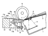
図1は、この実施の形態である用紙分離装置を示す分解斜視図、図2は、同実施の形態における用紙分離装置を模式的に示す断面図、図3は、同実施の形態における用紙分離装置を模式的に示す平面図である。
【0016】
図2において、1は上面部を開放した平たい箱型をなすカセットで、このカセット1の内部に配置された載置板2は、基端部(搬送方向上流側端部)がカセット1の底面部で枢支されて上下方向に揺動可能となっている。カセット1の内部には、圧縮コイルばねからなる押上げばね3が設けられ、この押上げばね3は載置板2を下側から支えて常時押上げている。
そして、用紙としての記録紙Pは、載置板2を一旦押し下げて下向きに揺動させた状態で載置板2の上に積層して載置し、その後に押上げばね3により載置板2を上向きに揺動させて、最上層の記録紙Pをカセット1に設けた図示しない押え爪により上側から押えている。このカセット1は、後述するように載置板2の先端部が分離搬送ローラ14に向かい合うようにして設けられる。
【0017】
本発明の用紙分離装置について説明する。
図中11はベース、12はガイド、13はホルダで、これらの各部品を合せて用紙分離装置の装置本体を構成している。ベース11は、カセット1に対して記録紙搬送方向下流側に配設されている。ガイド12は、記録紙搬送方向に対して直交する方向の長さ(幅)が、記録紙Pの同じ方向の長さに対応する大きさを有する細長いもので、ベース11における記録紙搬送方向上流側に搬送方向に対して直交する方向に沿って固定されている。ガイド12の長さ方向の中央部には、分離搬送ローラ14の外周面の下側部分に面する位置に開口部12aが形成され、この開口部12aにはホルダ13が配置固定されている。
【0018】
14は分離搬送ローラ、15は分離部材、16は分離ばね、17は一対の弾性保持部材17である。分離搬送ローラ14は、記録紙Pにおける搬送方向に対して直交する方向の長さ(幅)に対応する長さを有するもので、ガイド12の上側で搬送方向に対して直交する方向に沿って配置されている。なお、分離搬送ローラ14は、カセット1の搬送方向下流側端部の上側にもかかって配置される。分離搬送ローラ14は、長さ方向両端部が画像形成装置本体に設けた図示しない軸受により回転自在に保持され、同じく画像形成装置本体に設けた図示しない回転駆動機構により図示矢印で示す搬送方向へ向けて回転される。
【0019】
前述したホルダ13は、上面部が開放された横長の箱形をなすもので、ガイド12に形成された開口部12aに記録紙搬送方向に対して直交する方向に沿って配置され、ビス21によりベース11に取付けられている。このホルダ13は、記録紙搬送方向に対して直交する方向に位置する二つの端壁部を有し、これら両方の端壁部に支点軸用軸受部22が形成されている。図2に示すように、支点軸用軸受部22は、円形孔部22aと、この円形孔部22aの上端と端壁部の上縁とを結ぶ開放部22bとからなるもので、後述するように分離部材15の支点軸31を開放部22bを通して円形孔部22aに挿入、抜出しできるようになっている。また、ホルダ13の長さ方向中央部には、ばね保持部23が形成され、このばね保持部23には圧縮コイルばねからなる分離ばね16が立てた状態で保持されている。
【0020】
分離部材15は、ホルダ13の内部に記録紙搬送方向に対して直角な方向に沿って配置されるもので、分離搬送ローラ14の長さ方向中央部において、分離搬送ローラ14の外周面の下側部分に面する箇所に位置することになる。
分離部材15は、ホルダ13に収まる長さを有する横長の板部15aおよびこの板部15aの長さ方向両方の端壁部15bを有し、この両方の端壁部15bの外面には、夫々記録紙搬送方向に対して直角な方向に沿って外側へ延び出る支点軸31が形成されている。また、分離部材15の板部15aの上面部には弾性部材、例えばゴムシートからなるパッド32が当接されて貼り付けられている。そして、分離部材15はホルダ13の内部に配置されて、その両方の端壁部15bの支持軸31がホルダ13の端壁部に形成された軸受部22に夫々上下方向に揺動可能に保持され、パッド32が分離搬送ローラ14の外周面の下側部分に面する。
このため、分離部材15は、板部15aが分離搬送ローラ14の外周面の下側部分に対して接近、離間する方向に沿って揺動し、分離部材15が分離搬送ローラ14に接近する向きに揺動した時に、パッド32が分離搬送ローラ14の外周面の下側部分に接触し、分離部材15が分離搬送ローラ14から離間する向きに揺動した時に、パッド32が分離搬送ローラ14の外周面の下側部分から離間する。
【0021】
ここで、支点軸31は図2で示すように丸軸の両側部を切り落として、平行な一対の平行な面とこの一対の平行な面で挟まれる円弧面からなる長方形断面となっている。ホルダ13における軸受部22の円形孔部22aはその内周面が支点軸31の円弧面に接触する、あるいはその内周面が支点軸31の円弧面より外側に位置する大きさである。支点軸31を軸受部22に挿入する場合には、支点軸31の長方形断面が軸受部22の直径方向に沿うようにして軸受部22の外側から開放部22bを通過させて円形孔部22aに挿入して円形孔部22aの内部で支点軸31を回転させる。
【0022】
また、分離部材15がホルダ13に揺動可能に保持されると、分離部材15の下面にホルダ13に保持された分離ばね16の上端が当接する。これにより、分離部材15は常時分離ばね16に支えられて押し上げられて、支点軸31を支点として分離搬送ローラ14の外周面に向けて揺動し、パッド32が分離搬送ローラ14の外周面の下側部分に押圧接触する。
【0023】
一対の弾性保持部材17は、ガイド12における開口部12aの両端部に設けられて、分離部材15の両端部の支点軸31を夫々外側から軸線方向に沿って分離部材15の中央部に向けて力を加えて揺動可能に押圧保持するものである。
すなわち、一対の弾性保持部材17は金属板ばねからなるもので、取付け片部17aと保持片部17bとが並べて一体に形成され、さらにこの保持片部17bに並んで補強片部17cが一体に形成されている。この補強片部17cは、保持片部17bを補強するものである。保持片部17bは、取付け片部17aを支点として記録紙搬送方向とは直交する方向に沿って弾性変形が可能で、常時ガイド12および分離部材15の長さ方向中央部に向けて弾性力を作用するようになっている。
【0024】
一対の弾性保持部材17は、ガイド12における開口部12aの両方の端部において、ホルダ13における両方の端壁部の外側に位置して記録紙搬送方向に沿って配置され、且つ一対の弾性保持部材17の取付け片部17aは、ガイド12の上面に重ねて配置されて、例えば接着剤によりガイド12の上面に接着固定されている。
ホルダ13の両方の端壁部の軸受部22に挿通されて位置決めされた支点軸31は、記録紙搬送方向に対して直角な方向に沿って位置し、その端部がホルダ13の両方の端壁部の外側へ突出している。
図3に示すように、一対の弾性保持部材17の保持片部17bは、ガイド12の開口部12aの両方の端部において、ホルダ13の両方の端壁部の外側に位置するとともに、この端壁部の外側に突出している支点軸31の端面に当接する。これにより、一対の弾性保持部材17の保持片部17bは、各支点軸31を夫々外側から記録紙搬送方向に対して直角な方向(軸線方向)に沿って分離部材15の中央部に向けて弾性力を加えて押圧する。一対の弾性保持部材17の弾性力は、分離部材15の揺動を可能にする大きさである。
【0025】
従って、一対の弾性保持部材17は、支点軸31を支点として分離部材15を揺動可能に押圧保持する。この場合、一対の弾性保持部材17の保持片部17bは、各支点軸31を夫々外側から記録紙搬送方向に対して直角な方向(軸線方向)に沿って分離部材15の中央部に向けて力を加えているために、ホルダ13の各軸受部22の内周面が各支点軸31の外周面を受けて各支点軸31を揺動可能に保持することなく、換言すれば、各支点軸31に半径方向に沿う力を加えることなく、各支点軸31を保持(フローティング構造)することができる。
【0026】
そして、一対の弾性保持部材17が分離部材15の両端部の支点軸31を、夫々軸線方向に沿って分離部材15の中央部に向けて力を加えて押圧保持することにより、分離部材15に振動が発生しようとすると、一対の弾性保持部材17がその弾性を利用して振動を吸収する作用を行う構造となっている。
【0027】
このように構成された用紙分離装置では、分離搬送ローラ14の搬送方向への回転により積層されている記録紙Pを上層から分離搬送ローラ14と分離部材15のパッド32との接触部に向けて引き込み、回転する分離搬送ローラ14と分離部材のパッド32との摩擦により引き込んだ記録紙Pを一枚ずつ分離して送り出し搬送する。
【0028】
記録紙Pの分離を行う場合には、分離搬送ローラ14と分離部材15との間を記録紙Pが通過する時に、分離部材15が支点軸31を中心として分離搬送ローラ14に対して離間する向きに揺動し、記録紙Pが通過した後に分離ばね16に押された分離部材15が支点軸31を中心として分離搬送ローラ14に接近する向きに揺動してパッド32が分離搬送ローラ14の外周面に衝突する。
この揺動や衝突に伴い分離部材15に振動が発生しようとすると、分離部材15の両端部の支点軸31を保持する一対の弾性保持部材17がその弾性を利用して振動を吸収する。このため、一対の弾性保持部材17が用紙分離時における分離部材15の揺動、衝突に伴う振動を吸収して騒音の発生を抑えることができる。
【0029】
そして、ホルダ13の各軸受部22の内周面が各支点軸31の外周面を受けて各支点軸31を揺動可能に保持することなく、且つ分離部材15の支点軸31がホルダ13の軸受部22に半径方向に沿う力を持って押し付け接触することを回避しているので、分離部材15を揺動する上での抵抗を大幅に取り除き、分離ばね16の力を有効に生かしてパッド32を分離搬送ローラ14に押圧接触させて、記録紙Pの分離、搬送を行うことができる。
従って、記録紙Pの円滑な分離を維持しつつ、記録紙Pの分離時における分離部材15の騒音の発生を抑えることができる。
【0030】
さらに、この実施の形態では、一対の弾性保持部材17をガイド12の上面(記録紙搬送面)に取付けるので、ベース11にホルダ13およびガイド12を取付け、分離部材15および分離ばね16をホルダ13に組込んで用紙分離装置の基本部分を組立てた後に、一対の弾性保持部材17を取付けることができてその取付け作業が容易である。
【0032】
他の実施の形態について図4を参照して説明する。この図4は、前述した図1に対応するもので、図1と同じ部分は同じ符号を付して示している。
この実施の形態では、金属板ばねからなる一対の弾性保持部材41を連結部41aで一体に連結している。この一対の弾性保持部材41では、連結部41aをホルダ13と一緒にビス21でベース11に取付けている。
この実施の形態では、連結部41aで一体に連結した一対の弾性保持部材41を採用しているので、個別に製作して組立てる場合に比較して構成が簡素となり、製作、組立が容易であるという利点がある。
【0033】
さらに、本発明と関連性を有する参考例について図5を参照して説明する。この図5は前述した図1に対応するもので、図1と同じ部分は同じ符号を付して示している。図5では、一対の弾性保持部材として3種類のものを示している。
【0034】
図中42はスポンジなどの弾性材料により形成された筒体からなる一対の弾性保持部材で、これら一対の弾性保持部材42は支点軸31をホルダ13の両方の端壁部に形成された軸受部22に嵌合されて設けられ、支点軸31を挿通するとともに分離部材15の両方の端壁部15bを外側から軸線方向に沿って分離部材中央部に向けて力を加えて揺動可能に押圧保持している。
【0035】
図中43は金属や合成樹脂により形成されたワッシャ(座金)からなる一対の弾性保持部材で、この一対の弾性保持部材43は支点軸31をホルダ13の両方の端壁部に形成された軸受部22に嵌合されて設けられ、支点軸31を挿通するとともに分離部材15の両方の端壁部15bを外側から軸線方向に沿って分離部材中央部に向けて力を加えて揺動可能に押圧保持している。
【0036】
図中44は圧縮コイルばねからなる一対の弾性保持部材で、この一対の弾性保持部材44は支点軸31をホルダ13の両方の端壁部に形成された軸受部22に嵌合されて設けられ、支点軸31を挿通するとともに分離部材15の両方の端壁部15bを外側から軸線方向に沿って分離部材中央部に向けて力を加えて揺動可能に押圧保持している。
【0037】
このように分離部材15を保持する一対の弾性保持部材は、分離部材15の両端部を夫々外側から軸線方向に沿って前記分離部材中央部に向けて力を加えて揺動可能に押圧保持するもので、種々の形態を採用することができる。一対の弾性保持部材が押圧保持する分離部材の両端部とは、分離部材15の両方の端壁部15bと、この端壁部15bから突出する支点軸31の両方を含んでいる。
【0038】
なお、本発明は前述した実施の形態に限定されず、種々変形して実施することができる。例えば前述した実施の形態では、積層した記録紙を分離、搬送する装置に適用したが、積層した原稿を分離、搬送する装置に適用することも可能である。
【0039】
【発明の効果】
本発明によれば、用紙の円滑な分離を維持しつつ、用紙分離時における騒音の発生を抑えることができる。
【図面の簡単な説明】
【図1】 本発明の一実施の形態である用紙分離装置を示す分解斜視図。
【図2】 同実施の形態における用紙分離装置を模式的に示す断面図。
【図3】 同実施の形態における用紙分離装置を模式的に示す平面図。
【図4】 他の実施の形態である用紙分離装置を示す分解斜視図。
【図5】 本発明と関連性を有する参考例である用紙分離装置を示す分解斜視図。
【符号の説明】
1…カセット、11,12,13…装置本体(ベース、ガイド、ホルダ)、14…分離搬送ローラ、15…分離部材、16…分離ばね、17,41…弾性保持部材、22…軸受部、31…支点軸、P…用紙(記録紙)。[0001]
BACKGROUND OF THE INVENTION
The present invention relates to a sheet separating device provided in an image forming apparatus.
[0002]
[Prior art]
In an image forming apparatus such as a facsimile, a printer, or a copier, for example, a sheet separating apparatus that separates recording sheets made of stacked cut sheets one by one and conveys them to an image forming mechanism is provided. In many cases, the friction separation method is adopted.
[0003]
This type of sheet separating apparatus includes an apparatus main body having a fulcrum shaft bearing portion, a separation conveying roller that is rotatably provided in the apparatus main body and draws and conveys recording sheets stacked in a cassette, and the separation conveying roller. and arranged in parallel, the both ends has a pivot shaft disposed in the fulcrum shaft bearing portion of the apparatus main body with projecting along the axial direction, close to the separating and conveying roller the fulcrum shaft as a fulcrum, spaced direction swingably provided to, and a separating member for separating the recording sheet drawn into the separation conveyance roller in contact with the separating and conveying roller, provided in the apparatus main body, toward the separation conveyance roller against the separating member by applying a force anda separation spring for pressing contact with the separating and conveying roller separating member, the separation and the separation conveyance roller recording paper which is laminated by the rotation of the conveying direction of the separation conveyance roller from the upper layer While pulling toward the contact portion with the timber, by the friction between the separation conveyance roller and the separation member to rotate is to convey feed to separate the recording sheet one by one.
[0004]
In this paper separating apparatus, when the recording paper between the separation conveyance roller and the separation member is passed, after the separating member is slightly swung in the direction away from the separating and conveying roller about the pivot axis, the recording sheet has passed The separation member pushed by the separation spring slightly swings in the direction approaching the separation conveyance roller about the fulcrum shaft, and the separation member collides with the outer peripheral surface of the separation conveyance roller.
For this reason, every time the recording sheet is separated in the sheet separating apparatus, vibration and collision are generated by the separating member, and unpleasant noise is generated due to the vibration and collision.
[0005]
Therefore, in the paper separating apparatus, some countermeasures have been conventionally taken in order to perform quiet recording paper separation while suppressing generation of noise accompanying recording paper separation. The paper separating apparatus disclosed in Japanese Patent Application Laid-Open Nos. 7-133303 and 9-249321 is also intended to suppress the generation of noise. Separately from the separation spring that presses and contacts the separation member to the separation conveying roller, in addition an elastic force along the radial direction of the fulcrum shaft by the elastic member against the separating member, by causing pressing contact with the fulcrum shaft on the inner peripheral surface of the bearing portion of the apparatus main body, the vibrations of the separating member at the time of recording paper separating It is intended to suppress the generation of noise.
[0006]
[Problems to be solved by the invention]
However, in such a paper separating apparatus that performs frictional separation, a force along the radial direction of the fulcrum shaft is applied to the separating member by an elastic member for the purpose of suppressing noise generation by the separating member during recording paper separation. Since the fulcrum shaft is held in pressure contact with the bearing portion of the apparatus body, the fulcrum shaft swings and the friction at the pressing contact portion between the fulcrum shaft and the bearing portion prevents the oscillation. Thus, the separating member comes into contact with the separating and conveying roller and hinders the operation of separating the recording paper.
[0007]
That is, when the separation member is swung toward the separation conveyance roller with the fulcrum shaft as a fulcrum by the force of the separation spring, the friction at the pressing portion between the fulcrum shaft and the bearing portion becomes a resistance, and the separation member becomes the separation roller The pressure (separation pressure) that makes pressing contact with the outer peripheral surface is reduced, making it impossible to smoothly separate and transport the recording paper.
[0008]
Therefore, if the force that presses and contacts the fulcrum shaft of the separation member against the bearing portion of the apparatus main body is reduced by the elastic member, it becomes difficult to satisfactorily suppress the vibration of the separation member during recording paper separation, resulting in the generation of noise. It becomes difficult to suppress.
[0009]
An object of the present invention, while maintaining a smooth separation of paper is to provide a sheet separating apparatus capable of suppressing the generation of noise definitive during sheet separation.
[0010]
[Means for Solving the Problems]
In order to achieve the above object, a sheet separating apparatus according to one aspect of the present invention includes:
An apparatus main body having a bearing portion, a separation conveyance roller that is rotatably provided in the apparatus main body and draws and conveys sheets stacked in a cassette; and a pair of fulcrum shafts held by the bearing portion, A separation member that swings in a direction approaching and separating from the separation conveyance roller with a fulcrum shaft as a fulcrum, and that separates the paper drawn into the separation conveyance roller by contacting the separation conveyance roller; and the apparatus A separation spring provided on the main body and pressing the separation member toward the separation and conveyance roller to contact the separation member with the separation and conveyance roller, and abut against the fulcrum shaft of the separation member so as to be elastically deformable is fixed to the apparatus main body so as, by adding the elastic force toward the central portion of the separating member in the axial direction of the fulcrum shaft on the fulcrum shaft, the separating member rocking Is characterized by capable comprises a pair of elastic holding member for pressing and holding, the.
[0011]
According to the configuration of the present invention, the pair of elastic holding members absorbs the vibration of the separation member during the paper separation and the vibration accompanying the collision to suppress the generation of noise, and the fulcrum shaft of the separation member is the bearing portion of the apparatus main body. Thus, it is possible to avoid the pressing contact with the force along the radial direction and to largely eliminate the resistance to the swinging of the separating member. Therefore, the separation member can be pressed and brought into contact with the separation conveyance roller by effectively utilizing the force of the separation spring, and the paper can be separated and conveyed.
[0014]
DETAILED DESCRIPTION OF THE INVENTION
An embodiment of the present invention will be described with reference to FIGS.
In this embodiment, the image forming apparatus is applied to a sheet separating apparatus that sequentially separates and conveys recording sheets made of cut sheets stacked and accommodated in a cassette from the uppermost layer. Accordingly, the sheet separating device is provided on the downstream side in the recording sheet conveying direction with respect to the cassette in the image forming apparatus main body.
[0015]
Figure 1 is an exploded perspective view showing a sheet separating device in the form of this embodiment, FIG. 2 is a cross-sectional view schematically showing a sheet separation device according to the embodiment, FIG. 3, the sheet separation in the same embodiment It is a top view which shows an apparatus typically .
[0016]
In FIG. 2, reference numeral 1 denotes a flat box-shaped cassette whose upper surface is open. The
Then, the recording paper P as a sheet, mounting
[0017]
The sheet separating apparatus of the present invention will be described.
In the figure, 11 is a base, 12 is a guide, and 13 is a holder. These components are combined to constitute the main body of the sheet separating apparatus. The
[0018]
[0019]
The above-described
[0020]
Separating
Separating
Therefore, the separating
[0021]
Here, as shown in FIG. 2, the
[0022]
When the
[0023]
The pair of
That is, the pair of
[0024]
The pair of
As shown in FIG. 3, the holding
[0025]
Accordingly, the pair of
[0026]
The pair of
[0027]
In the sheet separating apparatus configured as described above, the recording sheets P stacked by the rotation of the separating and conveying
[0028]
When the separation of recording sheet P, when between the separating and conveying
When vibration is generated in the
[0029]
The inner peripheral surface of each bearing
Accordingly, it is possible to suppress the generation of noise of the separating
[0030]
Further, in this embodiment, since the pair of
[0032]
Another embodiment will be described with reference to FIG. This 4, which corresponds to FIG. 1 described above, the same parts as in FIG. 1 are denoted by the same reference numerals.
In this embodiment, a pair of
In this embodiment, since the pair of
[0033]
Further, a reference example related to the present invention will be described with reference to FIG. FIG. 5 corresponds to FIG. 1 described above, and the same parts as those in FIG. 1 are denoted by the same reference numerals. FIG. 5 shows three types of elastic holding members.
[0034]
In the figure,
[0035]
In the figure,
[0036]
In the figure,
[0037]
In this way, the pair of elastic holding members that hold the separating
[0038]
In addition, this invention is not limited to embodiment mentioned above, It can implement by changing variously. For example, in the above-described embodiment, the present invention is applied to an apparatus that separates and conveys stacked recording sheets. However, it can also be applied to an apparatus that separates and conveys stacked originals.
[0039]
【The invention's effect】
According to the present invention, generation of noise during sheet separation can be suppressed while maintaining smooth sheet separation.
[Brief description of the drawings]
FIG. 1 is an exploded perspective view showing a sheet separating apparatus according to an embodiment of the present invention.
FIG. 2 is a cross-sectional view schematically showing the sheet separating apparatus in the embodiment.
FIG. 3 is a plan view schematically showing the sheet separating apparatus according to the embodiment.
FIG. 4 is an exploded perspective view showing a paper separating apparatus according to another embodiment.
FIG. 5 is an exploded perspective view showing a paper separating apparatus which is a reference example related to the present invention .
[Explanation of symbols]
DESCRIPTION OF SYMBOLS 1 ... Cassette, 11, 12, 13 ... Apparatus main body (base, guide, holder), 14 ... Separation conveyance roller, 15 ... Separation member, 16 ... Separation spring, 17 , 41 ... Elastic holding member, 22 ... Bearing part, 31 ... fulcrum shaft, P ... paper (recording paper).
Claims (5)
軸受部を有する装置本体と、
この装置本体に回転自在に設けられ、前記カセットに積層された用紙を引き込んで搬送する分離搬送ローラと、
前記軸受部に保持される一対の支点軸を有し、この支点軸を支点として前記分離搬送ローラに対し接近離間する方向に揺動可能に設けられるとともに、前記分離搬送ローラに接触して前記分離搬送ローラに引き込まれた用紙を分離する分離部材と、
前記装置本体に設けられ、前記分離部材を前記分離搬送ローラに向けて押圧することで、前記分離部材を前記分離搬送ローラに接触させる分離ばねと、
前記分離部材の前記支点軸に弾性変形可能に当接するように前記装置本体に固定され、前記支点軸の軸線方向に沿って前記分離部材の中央部に向かう弾性力を前記支点軸に付加することで、前記分離部材を揺動可能に押圧保持する一対の弾性保持部材と、を具備することを特徴とする用紙分離装置。In a paper separation device that separates and transports paper stacked in a cassette,
An apparatus body having a bearing portion;
A separation conveyance roller that is rotatably provided in the apparatus main body and draws and conveys the sheets stacked in the cassette;
It has a pair of fulcrum shafts held by the bearing portion, and is provided so as to be able to swing in the direction of approaching and separating from the separation conveyance roller with the fulcrum shaft as a fulcrum, and in contact with the separation conveyance roller, the separation A separating member for separating the paper drawn into the conveying roller;
A separation spring that is provided in the apparatus main body and presses the separation member toward the separation conveyance roller to bring the separation member into contact with the separation conveyance roller;
The elastic member is fixed to the apparatus main body so as to be elastically deformable against the fulcrum shaft of the separation member, and an elastic force is applied to the fulcrum shaft along the axial direction of the fulcrum shaft toward the central portion of the separation member. And a pair of elastic holding members that press and hold the separating member in a swingable manner.
用紙を引き込んで搬送する分離搬送ローラと、A separation conveying roller for drawing and conveying the paper;
前記軸受部に保持される一対の支点軸を有し、この支点軸を支点として前記分離搬送ローラに対し接近離間する方向に揺動可能に設けられるとともに、前記分離搬送ローラに接触して前記分離搬送ローラに引き込まれた用紙を分離する分離部材と、A pair of fulcrum shafts held by the bearing portion are provided so as to be swingable in a direction approaching and separating from the separation conveyance roller with the fulcrum shaft as a fulcrum, and in contact with the separation conveyance roller, the separation A separating member for separating the paper drawn into the conveying roller;
前記分離部材を前記分離搬送ローラに向けて押圧することで、前記分離部材を前記分離搬送ローラに接触させる分離ばねと、A separation spring that makes the separation member contact the separation conveyance roller by pressing the separation member toward the separation conveyance roller;
前記分離部材の支点軸の端面に夫々弾性変形可能に当接する板ばねからなり、前記支点軸の軸線方向に沿って前記分離部材の中央部に向かう弾性力を前記支点軸に加えることで、前記分離部材を揺動可能に押圧保持する一対の弾性保持部材と、を具備することを特徴とする用紙分離装置。It consists of a leaf spring that abuts on the end face of the fulcrum shaft of the separating member so as to be elastically deformable, and by applying an elastic force to the fulcrum shaft along the axial direction of the fulcrum shaft to the fulcrum shaft, A sheet separating apparatus comprising: a pair of elastic holding members that press and hold the separating member in a swingable manner.
Priority Applications (2)
| Application Number | Priority Date | Filing Date | Title |
|---|---|---|---|
| JP2000259351A JP4408175B2 (en) | 2000-08-29 | 2000-08-29 | Paper separator |
| US09/939,100 US6554272B2 (en) | 2000-08-29 | 2001-08-24 | Sheet separation unit and image forming apparatus |
Applications Claiming Priority (1)
| Application Number | Priority Date | Filing Date | Title |
|---|---|---|---|
| JP2000259351A JP4408175B2 (en) | 2000-08-29 | 2000-08-29 | Paper separator |
Publications (3)
| Publication Number | Publication Date |
|---|---|
| JP2002068505A JP2002068505A (en) | 2002-03-08 |
| JP2002068505A5 JP2002068505A5 (en) | 2007-09-06 |
| JP4408175B2 true JP4408175B2 (en) | 2010-02-03 |
Family
ID=18747537
Family Applications (1)
| Application Number | Title | Priority Date | Filing Date |
|---|---|---|---|
| JP2000259351A Expired - Fee Related JP4408175B2 (en) | 2000-08-29 | 2000-08-29 | Paper separator |
Country Status (2)
| Country | Link |
|---|---|
| US (1) | US6554272B2 (en) |
| JP (1) | JP4408175B2 (en) |
Families Citing this family (6)
| Publication number | Priority date | Publication date | Assignee | Title |
|---|---|---|---|---|
| EP1179498B1 (en) * | 2000-08-08 | 2006-10-11 | Ricoh Company, Ltd. | Sheet feeding method and device for image forming apparatus |
| EP1334933B8 (en) * | 2002-02-08 | 2006-06-14 | Ricoh Company, Ltd. | Method and apparatus for sheet feeding and image forming apparatus incorporating the same |
| KR100507337B1 (en) * | 2002-12-11 | 2005-08-09 | 엘지엔시스(주) | A media separating apparatus for media dispenser |
| JP4408842B2 (en) | 2005-06-30 | 2010-02-03 | 株式会社リコー | Sheet conveying apparatus, automatic document conveying apparatus, paper feeding apparatus, and image forming apparatus |
| JP5298070B2 (en) * | 2009-12-22 | 2013-09-25 | 京セラドキュメントソリューションズ株式会社 | Paper feeding structure and image forming apparatus incorporating the paper feeding structure |
| JP5979389B2 (en) * | 2014-03-20 | 2016-08-24 | コニカミノルタ株式会社 | Image forming apparatus |
Family Cites Families (5)
| Publication number | Priority date | Publication date | Assignee | Title |
|---|---|---|---|---|
| JPH0780578B2 (en) * | 1988-09-28 | 1995-08-30 | 株式会社テック | Paper feeder for office equipment |
| JPH0767989B2 (en) * | 1988-09-28 | 1995-07-26 | 株式会社テック | Paper feeder for office equipment |
| JP3244891B2 (en) | 1993-11-09 | 2002-01-07 | キヤノン株式会社 | Sheet feeding apparatus and image forming apparatus |
| JPH09249321A (en) | 1996-03-13 | 1997-09-22 | Canon Inc | Sheet feed device and picture image forming device |
| JP3767061B2 (en) * | 1997-02-05 | 2006-04-19 | ブラザー工業株式会社 | Printing device |
-
2000
- 2000-08-29 JP JP2000259351A patent/JP4408175B2/en not_active Expired - Fee Related
-
2001
- 2001-08-24 US US09/939,100 patent/US6554272B2/en not_active Expired - Fee Related
Also Published As
| Publication number | Publication date |
|---|---|
| US6554272B2 (en) | 2003-04-29 |
| US20020060395A1 (en) | 2002-05-23 |
| JP2002068505A (en) | 2002-03-08 |
Similar Documents
| Publication | Publication Date | Title |
|---|---|---|
| JP3731260B2 (en) | Paper feeding device and image recording apparatus including the same | |
| JP4408175B2 (en) | Paper separator | |
| JP5395015B2 (en) | Sheet feeding device | |
| JP2571311Y2 (en) | Paper feeder | |
| JP6264032B2 (en) | Sheet separation device | |
| JP2533566B2 (en) | Sheet feeding device | |
| JP2002154694A (en) | Paper feeder | |
| JP2004018217A (en) | Paper inversion mechanism in laser printer and paper inversion mechanism in image formation device | |
| JP3238070B2 (en) | Printing device feeder | |
| JP3066119B2 (en) | Paper feeder of image forming device | |
| JPH02108945U (en) | ||
| JPH0661846U (en) | Paper separator | |
| JP6052373B2 (en) | Sheet feeding device | |
| JP5760329B2 (en) | Sheet feeding device | |
| JPH1179447A (en) | Paper feeder | |
| JP2007297198A (en) | Conveying device, image forming device, and method of separating conveying rollers | |
| JP3760651B2 (en) | Sheet transport device | |
| JP5846266B2 (en) | Sheet feeding device | |
| JPH041555Y2 (en) | ||
| JP3332068B2 (en) | Paper feed mechanism | |
| JPS6129294B2 (en) | ||
| JP3710407B2 (en) | Sheet feeding apparatus and image forming apparatus provided with the same | |
| JPH05201570A (en) | Paper feed device | |
| JP2000318851A (en) | Paper carrying device | |
| JPH05278883A (en) | Paper sheet separating device |
Legal Events
| Date | Code | Title | Description |
|---|---|---|---|
| A521 | Request for written amendment filed |
Free format text: JAPANESE INTERMEDIATE CODE: A523 Effective date: 20070720 |
|
| A621 | Written request for application examination |
Free format text: JAPANESE INTERMEDIATE CODE: A621 Effective date: 20070720 |
|
| A711 | Notification of change in applicant |
Free format text: JAPANESE INTERMEDIATE CODE: A711 Effective date: 20070720 |
|
| A977 | Report on retrieval |
Free format text: JAPANESE INTERMEDIATE CODE: A971007 Effective date: 20090529 |
|
| A131 | Notification of reasons for refusal |
Free format text: JAPANESE INTERMEDIATE CODE: A131 Effective date: 20090609 |
|
| A521 | Request for written amendment filed |
Free format text: JAPANESE INTERMEDIATE CODE: A523 Effective date: 20090803 |
|
| TRDD | Decision of grant or rejection written | ||
| A01 | Written decision to grant a patent or to grant a registration (utility model) |
Free format text: JAPANESE INTERMEDIATE CODE: A01 Effective date: 20091104 |
|
| A01 | Written decision to grant a patent or to grant a registration (utility model) |
Free format text: JAPANESE INTERMEDIATE CODE: A01 |
|
| A61 | First payment of annual fees (during grant procedure) |
Free format text: JAPANESE INTERMEDIATE CODE: A61 Effective date: 20091106 |
|
| R150 | Certificate of patent or registration of utility model |
Free format text: JAPANESE INTERMEDIATE CODE: R150 |
|
| FPAY | Renewal fee payment (event date is renewal date of database) |
Free format text: PAYMENT UNTIL: 20121120 Year of fee payment: 3 |
|
| FPAY | Renewal fee payment (event date is renewal date of database) |
Free format text: PAYMENT UNTIL: 20131120 Year of fee payment: 4 |
|
| LAPS | Cancellation because of no payment of annual fees |