JP4406428B2 - Signal separation device, signal separation method, signal separation program, and recording medium - Google Patents
Signal separation device, signal separation method, signal separation program, and recording medium Download PDFInfo
- Publication number
- JP4406428B2 JP4406428B2 JP2006520556A JP2006520556A JP4406428B2 JP 4406428 B2 JP4406428 B2 JP 4406428B2 JP 2006520556 A JP2006520556 A JP 2006520556A JP 2006520556 A JP2006520556 A JP 2006520556A JP 4406428 B2 JP4406428 B2 JP 4406428B2
- Authority
- JP
- Japan
- Prior art keywords
- signal
- vector
- frequency
- unit
- normalization
- Prior art date
- Legal status (The legal status is an assumption and is not a legal conclusion. Google has not performed a legal analysis and makes no representation as to the accuracy of the status listed.)
- Active
Links
Images


Classifications
-
- G—PHYSICS
- G10—MUSICAL INSTRUMENTS; ACOUSTICS
- G10L—SPEECH ANALYSIS OR SYNTHESIS; SPEECH RECOGNITION; SPEECH OR VOICE PROCESSING; SPEECH OR AUDIO CODING OR DECODING
- G10L21/00—Processing of the speech or voice signal to produce another audible or non-audible signal, e.g. visual or tactile, in order to modify its quality or its intelligibility
- G10L21/02—Speech enhancement, e.g. noise reduction or echo cancellation
- G10L21/0272—Voice signal separating
-
- G—PHYSICS
- G06—COMPUTING; CALCULATING OR COUNTING
- G06F—ELECTRIC DIGITAL DATA PROCESSING
- G06F18/00—Pattern recognition
- G06F18/20—Analysing
- G06F18/21—Design or setup of recognition systems or techniques; Extraction of features in feature space; Blind source separation
- G06F18/213—Feature extraction, e.g. by transforming the feature space; Summarisation; Mappings, e.g. subspace methods
- G06F18/2134—Feature extraction, e.g. by transforming the feature space; Summarisation; Mappings, e.g. subspace methods based on separation criteria, e.g. independent component analysis
- G06F18/21347—Feature extraction, e.g. by transforming the feature space; Summarisation; Mappings, e.g. subspace methods based on separation criteria, e.g. independent component analysis using domain transformations
-
- G—PHYSICS
- G10—MUSICAL INSTRUMENTS; ACOUSTICS
- G10L—SPEECH ANALYSIS OR SYNTHESIS; SPEECH RECOGNITION; SPEECH OR VOICE PROCESSING; SPEECH OR AUDIO CODING OR DECODING
- G10L15/00—Speech recognition
- G10L15/20—Speech recognition techniques specially adapted for robustness in adverse environments, e.g. in noise, of stress induced speech
-
- G—PHYSICS
- G10—MUSICAL INSTRUMENTS; ACOUSTICS
- G10L—SPEECH ANALYSIS OR SYNTHESIS; SPEECH RECOGNITION; SPEECH OR VOICE PROCESSING; SPEECH OR AUDIO CODING OR DECODING
- G10L21/00—Processing of the speech or voice signal to produce another audible or non-audible signal, e.g. visual or tactile, in order to modify its quality or its intelligibility
- G10L21/02—Speech enhancement, e.g. noise reduction or echo cancellation
- G10L21/0208—Noise filtering
- G10L21/0216—Noise filtering characterised by the method used for estimating noise
- G10L2021/02161—Number of inputs available containing the signal or the noise to be suppressed
- G10L2021/02165—Two microphones, one receiving mainly the noise signal and the other one mainly the speech signal
Landscapes
- Engineering & Computer Science (AREA)
- Physics & Mathematics (AREA)
- Theoretical Computer Science (AREA)
- Data Mining & Analysis (AREA)
- Computer Vision & Pattern Recognition (AREA)
- Life Sciences & Earth Sciences (AREA)
- Bioinformatics & Cheminformatics (AREA)
- Audiology, Speech & Language Pathology (AREA)
- Acoustics & Sound (AREA)
- Multimedia (AREA)
- Health & Medical Sciences (AREA)
- Signal Processing (AREA)
- Quality & Reliability (AREA)
- Artificial Intelligence (AREA)
- Human Computer Interaction (AREA)
- Bioinformatics & Computational Biology (AREA)
- Evolutionary Biology (AREA)
- Evolutionary Computation (AREA)
- General Engineering & Computer Science (AREA)
- General Physics & Mathematics (AREA)
- Computational Linguistics (AREA)
- Circuit For Audible Band Transducer (AREA)
- Measurement And Recording Of Electrical Phenomena And Electrical Characteristics Of The Living Body (AREA)
- Indication And Recording Devices For Special Purposes And Tariff Metering Devices (AREA)
Description
本発明は、信号処理の技術分野に属し、特に複数の源信号が空間内で混合された混合信号から源信号を抽出する技術に関する。 The present invention belongs to the technical field of signal processing, and particularly relates to a technique for extracting a source signal from a mixed signal obtained by mixing a plurality of source signals in a space.
複数のセンサを用いることによりある信号を抽出してその他の信号を抑圧する従来の技術として、ビームフォーマ(beamformer)(ビームフォーミング(beamforming)とも呼ぶ)が広く知られている(例えば、非特許文献1参照)。しかし、ビームフォーマでは、目的信号の方向に関する情報を必要とするため、そのような情報が得られない(または推定できない)状況では利用しにくいという欠点がある。
また、より新しい別の技術としては、ブラインド信号分離(BSS:Blind Signal Separation)が挙げられる(例えば、非特許文献2参照)。これは、上記ビームフォーマが必要とした情報を必要としないという点で優れており、様々な状況での利用が期待されている。以下、このブラインド信号分離による信号分離について説明する。As a conventional technique for extracting a signal by using a plurality of sensors and suppressing other signals, a beamformer (also referred to as beamforming) is widely known (for example, non-patent literature). 1). However, since the beam former requires information on the direction of the target signal, there is a drawback that it is difficult to use in a situation where such information cannot be obtained (or cannot be estimated).
Another newer technique is blind signal separation (BSS: Blind Signal Separation) (see Non-Patent
[ブラインド信号分離]
まず、ブラインド信号分離の定式化を行う。すべての信号はあるサンプリング周波数fsでサンプリングされ、離散的に表現されるものとする。また、N個の信号が混合されてM個のセンサで観測されたとする。以下では、信号の発生源からセンサまでの距離により信号が減衰・遅延し、また壁などにより信号が反射して伝送路の歪みが発生しうる状況を扱う。このような状況で混合される信号は、信号源kからセンサq(qはセンサの番号を示す〔q=1,…,M〕。また、kは信号源の番号を示す〔k=1,…,N〕。)へのインパルス応答hqk(r)による畳み込み混合[Blind signal separation]
First, the blind signal separation is formulated. All signals are sampled at a sampling frequency f s and expressed discretely. Further, it is assumed that N signals are mixed and observed by M sensors. The following deals with a situation in which the signal is attenuated / delayed depending on the distance from the signal generation source to the sensor, and the signal may be reflected by a wall or the like to cause distortion of the transmission path. The signal mixed in such a situation is transmitted from the signal source k to the sensor q (q is a sensor number [q = 1,..., M]. K is a signal source number [k = 1, ..., N].) Convolutional mixing with impulse response h qk (r)

一般的なインパルス応答hqk(r)は、適当な時間経過後にパルス的な強い応答を持ち、時間と共に減衰していく。ブラインド信号分離の目的は、源信号s1(t),…,sN(t)やインパルス応答h11(r),…,h1N(r),…,hM1(r),…,hMN(r)を知らずに、観測信号(以下「混合信号」と呼ぶ)x1(t),…,xM(t)のみから、源信号s1(t),…,sN(t)にそれぞれ対応する分離信号y1(t),…,yN(t)を求めることにある。
General impulse response h qk (r) has a pulsed strong response after an appropriate period of time, decays with time. The purpose of blind signal separation is the source signal s 1 (t), ..., s N (t) and impulse response h 11 (r), ..., h 1N (r), ..., h M1 (r), ..., h Without knowing MN (r), only source signals s 1 (t), ..., s N (t) are obtained from the observed signals (hereinafter referred to as "mixed signals") x 1 (t), ..., x M (t) the corresponding separated signals y 1 (t), ..., is to seek y N (t).
[周波数領域]
次に、従来のブラインド信号分離の手順について説明する。
ここでは周波数領域において分離の操作を行う。そのためにセンサqでの混合信号xq(t)にL点の短時間離散フーリエ変換(STFT:Short-Time Fourier Transform)を適用し、周波数ごとの時間系列[Frequency domain]
Next, a conventional blind signal separation procedure will be described.
Here, the separation operation is performed in the frequency domain. For this purpose, an L-point short-time Fourier transform (STFT) is applied to the mixed signal x q (t) at the sensor q, and a time series for each frequency.
周波数領域で処理を行うと、式(1)で示される時間領域での畳み込み混合が、
When processing is performed in the frequency domain, convolutional mixing in the time domain represented by Equation (1) is
[独立成分分析による信号分離]
ブラインド信号分離手法の1つとして、独立成分分析(ICA:Independent Component Analysis) による信号分離がある。このICAによる手法では、混合信号ベクトルX(f,τ)のみから、N行M列の分離行列W(f)及び分離信号ベクトル
Y(f,τ)=W(f)X(f,τ) …(5)
を算出する。ここで、分離行列W(f)は、分離信号ベクトルY(f,τ)=[Y1(f,τ),...,YN(f,τ)]Tの各要素(分離信号)Y1(f,τ),...,YN(f,τ)が互いに独立になるように算出される。そのためのアルゴリズムには、非特許文献4に記載されているものなどがある。
[Signal separation by independent component analysis]
One of the blind signal separation methods is signal separation by independent component analysis (ICA). In this ICA method, the separation matrix W (f) and the separation signal vector of N rows and M columns are obtained from only the mixed signal vector X (f, τ).
Y (f, τ) = W (f) X (f, τ) (5)
Is calculated. Here, the separation matrix W (f) is the separation signal vector Y (f, τ) = [Y 1 (f, τ), ..., Y N (f, τ)] T elements (separation signals) Y 1 (f, τ),..., Y N (f, τ) are calculated so as to be independent from each other. There are algorithms described in Non-Patent
ICAでは信号の独立性に着目して分離を行うため、得られる分離信号Y1(f,τ),...,YN(f,τ)には、順序の任意性がある。信号の順序が入れ替わってもそれらの独立性は保たれるからである。この順序の任意性の問題は、パーミュテーション(permutation)の問題と呼ばれ、周波数領域での信号分離において非常に重要な問題である。そして、このパーミュテーションの問題は、同じ源信号Sk(f,τ)に対応する分離信号Yp(f,τ)の添字pが、すべての周波数fで同じになるように解決されなければならない。
このパーミュテーション問題を解決する従来手法として、例えば非特許文献5に示されるものがある。この手法では、選択された2つのセンサ(センサペア)の位置を基準として信号源の位置に関する情報(方向と距離比)を推定する。そして、複数のセンサペアでの推定値を統合することで、より詳細な位置情報が得られる。そして、これらの位置情報としての推定値をクラスタリングし、同じクラスタに属する推定値は同じ信号源に対応するものとみなしてパーミュテーション問題を解決する。Since the separation is performed by focusing on signal independence in ICA, the obtained separated signals Y 1 (f, τ),..., Y N (f, τ) have an arbitrary order. This is because their independence is maintained even if the order of the signals is changed. The problem of arbitraryness of order is called a permutation problem, and is a very important problem in signal separation in the frequency domain. This permutation problem must be solved so that the subscript p of the separated signal Y p (f, τ) corresponding to the same source signal S k (f, τ) is the same at all frequencies f. I must.
As a conventional method for solving this permutation problem, for example, there is one disclosed in
[時間周波数マスクによる信号分離]
また、他のブラインド信号分離手法として、時間周波数マスクによる方法がある。この手法は、信号源の数Nとセンサ数MがM<Nの関係にある場合でも有効な信号分離抽出手法である。
この手法では信号のスパース性を仮定する。スパースとは、信号が殆どの離散時間τにおいて0であることを指す。信号のスパース性は、例えば、周波数領域での音声信号で確認される。信号のスパース性と相互独立性を仮定することで、複数の信号が同時に存在していても、各時間周波数ポイント(f,τ)では互いに重なって観測される確率が低いことを仮定できる。よって、各時間周波数ポイント(f,τ)の各センサにおける混合信号は、その時間周波数ポイント(f,τ)でアクティブな1つの信号sp(f,τ)のみから成ると仮定できる。よって、混合信号ベクトルを適当な特徴量によりクラスタリングし、各クラスタCkのメンバの時間周波数(f,τ)に対応する混合信号X(f,τ)を抽出する時間周波数マスクMk(f,τ)を推定し、
Yk(f,τ)=Mk(f,τ)XQ'(f,τ)
により、各信号を分離抽出する。ここで、XQ'(f,τ)は混合信号のうちの1つであり、Q’∈{1,…,M}である。[Signal separation by time frequency mask]
As another blind signal separation method, there is a method using a time-frequency mask. This method is an effective signal separation and extraction method even when the number N of signal sources and the number M of sensors are in a relationship of M <N.
This method assumes signal sparsity. Sparse refers to the signal being zero at most discrete times τ. The sparsity of the signal is confirmed by an audio signal in the frequency domain, for example. By assuming the sparseness and mutual independence of signals, it can be assumed that even if a plurality of signals exist simultaneously, the probability that they are observed overlapping each other at each time frequency point (f, τ) is low. Thus, mixed signal at each sensor of each time-frequency point (f, tau) may be assumed that time-frequency point (f, tau) in the active one signal s p (f, τ) and consist only. Therefore, the mixed frequency vector M k (f, τ) for clustering the mixed signal vector with an appropriate feature quantity and extracting the mixed signal X (f, τ) corresponding to the time frequency (f, τ) of each cluster C k member. τ),
Y k (f, τ) = M k (f, τ) X Q ' (f, τ)
Thus, each signal is separated and extracted. Here, X Q ′ (f, τ) is one of the mixed signals, and Q′ε {1,..., M}.
クラスタリングに用いる特徴量としては、例えば、2つのセンサ(センサqと基準センサQ〔なお、Qを基準値と呼び、基準値Qに対応するセンサを基準センサQと表記する。〕)における混合信号の位相差 As the feature quantity used for clustering, for example, a mixed signal in two sensors (sensor q and reference sensor Q (Q is referred to as a reference value, and a sensor corresponding to the reference value Q is referred to as a reference sensor Q)). Phase difference
から計算される信号の推定到来方向(Direction of Arrival : DOA)
Direction of arrival (DOA) of the signal calculated from
を例示できる(例えば、非特許文献3参照)。なお、dはセンサqと基準センサQとの距離であり、cは信号速度である。また、クラスタリングには、k-means法(例えば、非特許文献6参照)等を用いることができる。また、時間周波数マスクMk(f,τ)としては、例えばそれぞれのクラスタCkに属するメンバの平均値θ1 〜 ,θ2 〜,…,θN 〜を求め、
(For example, refer nonpatent literature 3). Here, d is the distance between the sensor q and the reference sensor Q, and c is the signal speed. In addition, k-means method (for example, see Non-Patent Document 6) or the like can be used for clustering. Further, as the time frequency mask M k (f, τ), for example, average values θ 1 to , θ 2 to ,..., Θ N to members belonging to the respective clusters C k are obtained,
その他、クラスタリングの特徴量として、2つのセンサ(センサqと基準センサQ)における混合信号の位相差(式(8))や両者のゲイン比
In addition, as a clustering feature amount, the phase difference (formula (8)) of the mixed signals in the two sensors (sensor q and reference sensor Q) and the gain ratio between the two signals
しかし、上述した従来の技術では、複数のセンサによる観測信号から得られた情報を容易かつ効率的に利用して信号分離処理を行うことができないという問題点があった。
例えば、独立成分分析による信号分離の場合、正確にパーミュテーション問題を解決するためには繁雑な操作が必要となるという問題がある。すなわち、従来のパーミュテーション問題の解決手法では、センサペア毎に方向と距離比とが推定される。従って、正確にパーミュテーション問題を解決するためには複数のセンサペアでの推定値を統合する必要があった。また、この推定値には誤差が含まれているが、より誤差が少ないと思われるセンサペアを優先的に用いたり、誤差をうまく吸収できるように統合方法を工夫したりする必要があった。さらに、この従来手法では、信号源の位置に関する情報を推定する必要性から、センサの位置情報をあらかじめ取得しておかなければならないという問題点もあった。これはセンサを不規則に配置する場合に不利である。また、たとえセンサを規則的に配置するとしても、配置情報を厳密に知ることは困難であり、より正確なパーミュテーション問題の解決のためにはキャリブレーションなどの操作を必要とする。However, the above-described conventional technique has a problem in that signal separation processing cannot be performed easily and efficiently using information obtained from observation signals from a plurality of sensors.
For example, in the case of signal separation by independent component analysis, there is a problem that complicated operations are required to accurately solve the permutation problem. That is, in the conventional technique for solving the permutation problem, the direction and the distance ratio are estimated for each sensor pair. Therefore, in order to solve the permutation problem accurately, it is necessary to integrate the estimated values of a plurality of sensor pairs. Further, although this estimated value includes an error, it is necessary to preferentially use a sensor pair that seems to have a smaller error, or to devise an integration method so that the error can be absorbed well. Furthermore, this conventional method has a problem that the position information of the sensor has to be acquired in advance because of the need to estimate the information regarding the position of the signal source. This is disadvantageous when the sensors are arranged irregularly. Further, even if the sensors are regularly arranged, it is difficult to know the arrangement information precisely, and an operation such as calibration is required to solve a more accurate permutation problem.
また、従来の時間周波数マスクによる信号分離手法の場合、センサが2個の場合のための手法しか提案されておらず、センサが3個以上ある場合であっても、そのうち特定の2つのセンサq,Qのみの情報しか用いずに特徴量を計算していた。これは次元の低下を意味し、全てのセンサを用いる場合に比べて情報量が欠落する。そのため、全てのセンサの情報を効率的に使えず性能に限度があった。また、全てのセンサの情報を有効利用するには、例えば、非特許文献5にならって、複数のセンサペアで求めた特徴量を統合することも可能であろうが、この統合のためには、特徴量抽出のための更なる処理が必要であり、より統合誤差が少ないと思われるセンサペアを優先的に用いるなど、統合の際に工夫する必要があると思われる。さらに、この手法でも、センサの厳密な配置情報をあらかじめ知っておかなければならないという問題点がある。これは、センサを自由に配置する場合に不利である。また、たとえ規則的に配置するとしても、配置情報を厳密に知ることは困難であり、より正確な信号抽出のためにはキャリブレーションなどの操作を必要とする。
In the case of the conventional signal separation method using the time-frequency mask, only a method for the case of two sensors has been proposed. Even when there are three or more sensors, two specific sensors q , The feature amount is calculated using only information of Q. This means a reduction in dimension, and the amount of information is lost as compared to the case where all sensors are used. For this reason, the information of all the sensors cannot be used efficiently, and the performance is limited. Further, in order to effectively use the information of all sensors, for example, it is possible to integrate feature amounts obtained by a plurality of sensor pairs in accordance with
さらに、ブラインド信号分離の処理の基本は、センサで観測された混合信号を分離して、複数の分離信号を出力することである。しかし、すべての分離信号が重要なわけではなく、一部の分離信号のみに目的とする目的信号が含まれていることもある。そのような場合、目的信号が含まれている分離信号を選択する必要があるが、従来のブラインド信号分離では、どの分離信号に目的信号が含まれているかという情報までは提供されない。従って、何らかの別の手段によって、どの分離信号に目的信号が含まれているかを判定しなければならない。 Furthermore, the basic of the blind signal separation process is to separate the mixed signal observed by the sensor and output a plurality of separated signals. However, not all the separated signals are important, and only a part of the separated signals may include a target signal of interest. In such a case, it is necessary to select a separated signal that includes the target signal, but conventional blind signal separation does not provide information on which separated signal includes the target signal. Therefore, it is necessary to determine which separated signal includes the target signal by some other means.
本発明はこのような点に鑑みてなされたものであり、複数のセンサによる観測信号から得られた情報を容易かつ効率的に利用して信号分離処理を行うことが可能な技術を提供することを目的とする。 The present invention has been made in view of these points, and provides a technique capable of performing signal separation processing by using information obtained from observation signals from a plurality of sensors easily and efficiently. With the goal.
本発明では、上記課題を解決するために、まず、周波数領域変換部が、複数のセンサで観測された混合信号を、周波数領域の混合信号に変換する。次に、正規化部が、当該周波数領域の混合信号を用いて生成された複素ベクトルを正規化し、当該複素ベクトルの周波数依存性を排除した正規化ベクトルを生成する。次に、クラスタリング部が、当該正規化ベクトルをクラスタリングし、クラスタを生成する。そして、このクラスタを用いて信号分離処理を行う。
ここで、当該クラスタの生成には、混合信号を観測する各センサの厳密な位置情報を、入力情報として直接用いることは必要としない。また、各クラスタは、各信号源の位置に依存する情報に基づき形成される。これらより、本発明では、各センサの厳密な位置情報を用いることなく、信号分離処理が可能となる。In the present invention, in order to solve the above-described problem, first, the frequency domain conversion unit converts the mixed signals observed by a plurality of sensors into mixed signals in the frequency domain. Next, a normalization part normalizes the complex vector produced | generated using the mixed signal of the said frequency domain, and produces | generates the normalization vector which excluded the frequency dependence of the said complex vector. Next, the clustering unit clusters the normalized vectors to generate a cluster. Then, signal separation processing is performed using this cluster.
Here, in order to generate the cluster, it is not necessary to directly use the exact position information of each sensor that observes the mixed signal as input information. Each cluster is formed based on information depending on the position of each signal source. Accordingly, in the present invention, signal separation processing can be performed without using strict position information of each sensor.
また、本発明において好ましくは、正規化部は、複素ベクトルが具備する特定の1つの要素を基準として当該複素ベクトルの各要素の偏角を正規化する第1正規化部と、第1正規化部で正規化された各要素の偏角を周波数に比例した値で除算する第2正規化部とを有する。
これらの正規化後の複素ベクトルは、信号源の位置に依存したクラスタを形成する。これにより、各センサの厳密な位置情報を用いることなく、信号分離処理を行うことが可能となる。In the present invention, it is preferable that the normalization unit includes a first normalization unit that normalizes a declination of each element of the complex vector with reference to one specific element included in the complex vector, and a first normalization unit A second normalization unit that divides the declination of each element normalized by the unit by a value proportional to the frequency.
These normalized complex vectors form a cluster depending on the position of the signal source. This makes it possible to perform signal separation processing without using strict position information of each sensor.
また、本発明において好ましくは、正規化部は、第2正規化部で正規化された各要素からなるベクトルのノルムを所定の値に正規化する第3正規化部をさらに有する。
これらの正規化後の複素ベクトルは、信号源の位置に依存したクラスタを形成する。また、第2正規化された各要素からなるベクトルのノルムを正規化することにより、クラスタリングの処理が簡略化される。
また、好ましい第1の本発明では、まず、周波数領域変換部が、複数のセンサで観測された混合信号を、周波数領域の混合信号に変換する。次に、分離行列算出部が、周波数領域の混合信号を用いて、周波数毎に分離行列を算出し、逆行列算出部が、分離行列の一般化逆行列を算出する。次に、基底ベクトル正規化部が、一般化逆行列を構成する基底ベクトルの正規化を行い、正規化基底ベクトルを算出する。次に、クラスタリング部が、正規化基底ベクトルをクラスタリングし、クラスタを生成する。その後、順列算出部が、クラスタの中心ベクトルと正規化基底ベクトルとを用い、分離行列の要素を並び替えるための順列を算出する。なお、基底ベクトルは、複素ベクトルに含まれる概念である。In the present invention, it is preferable that the normalization unit further includes a third normalization unit that normalizes a norm of a vector composed of each element normalized by the second normalization unit to a predetermined value.
These normalized complex vectors form a cluster depending on the position of the signal source. Further, by normalizing the norm of the vector composed of the second normalized elements, the clustering process is simplified.
In a preferred first aspect of the present invention, first, the frequency domain converter converts the mixed signals observed by a plurality of sensors into mixed signals in the frequency domain. Next, the separation matrix calculation unit calculates a separation matrix for each frequency using the frequency domain mixed signal, and the inverse matrix calculation unit calculates a generalized inverse matrix of the separation matrix. Next, the basis vector normalization unit normalizes the basis vectors constituting the generalized inverse matrix to calculate a normalized basis vector. Next, the clustering unit clusters the normalized basis vectors to generate a cluster. Thereafter, the permutation calculating unit calculates a permutation for rearranging the elements of the separation matrix using the cluster center vector and the normalized basis vector. Note that the basis vector is a concept included in the complex vector.
この第1の本発明では、基底ベクトルを正規化してクラスタリングし、パーミュテーション問題解決のための順列を算出する。そのため、このクラスタリングに際し、センサの位置情報をあらかじめ取得しておく必要がない。さらに、この好ましい本発明では、正規化基底ベクトルのすべての要素を対象としてクラスタリングを行い、その結果からパーミュテーション問題解決のための順列を算出する。そのため、従来のように推定結果を統合するための操作を必要としない。
また、当該第1の本発明において、より好ましくは、基底ベクトル正規化部は、基底ベクトルの周波数依存性を排除する正規化を行う。そして、より好ましくは、当該基底ベクトルの周波数依存性を排除する正規化は、基底ベクトルが具備する特定の1つの要素を基準として当該基底ベクトルの各要素の偏角を正規化し、さらに、各要素の偏角を周波数に比例した値で除算する正規化である。このような正規化により、信号源の位置に依存したクラスタの形成が可能となる。In the first aspect of the present invention, the basis vectors are normalized and clustered to calculate a permutation for solving the permutation problem. Therefore, it is not necessary to acquire sensor position information in advance for this clustering. Furthermore, in the present invention, clustering is performed for all elements of the normalized basis vector, and a permutation for solving the permutation problem is calculated from the result. Therefore, an operation for integrating estimation results as in the conventional case is not required.
In the first aspect of the present invention, more preferably, the basis vector normalization unit performs normalization that eliminates the frequency dependence of the basis vector. More preferably, the normalization that eliminates the frequency dependence of the basis vector normalizes the declination of each element of the basis vector with reference to one specific element included in the basis vector, and further each element Is a normalization in which the declination of is divided by a value proportional to the frequency. Such normalization makes it possible to form clusters depending on the position of the signal source.
また、当該第1の本発明において、より好ましくは、基底ベクトルの周波数依存性を排除する正規化は、基底ベクトルAp(f)(p=1,...,N、Nは信号源の数)の各要素Aqp(f)(q=1,...,M、Mは混合信号を観測するセンサの数)に対し、In the first aspect of the present invention, more preferably, the normalization for eliminating the frequency dependence of the basis vectors is the basis vectors A p (f) (p = 1,..., N, N are the signal sources) For each element A qp (f) (q = 1,..., M, M is the number of sensors observing the mixed signal),
また、上述の式(10)の実数dは、要素AQp(f)に対応する基準センサQと他のセンサとの最大距離dmaxであることが望ましい。クラスタリングの精度が一般的に向上するからである。この詳細は後述する。
また、第1の本発明において好ましくは、基底ベクトルを周波数に依存しない周波数正規化ベクトルに正規化し、この周波数正規化ベクトルをノルムが規定値をとる正規化基底ベクトルに正規化する。以上の二段階の正規化によって生成された正規化基底ベクトルは、周波数に依存せず、信号源の位置のみに依存する。なお、ノルムの正規化により、クラスタリングの処理が簡略化できる。In addition, the real number d in the above equation (10) is preferably the maximum distance d max between the reference sensor Q corresponding to the element A Qp (f) and another sensor. This is because the accuracy of clustering is generally improved. Details of this will be described later.
Preferably, in the first aspect of the present invention, the basis vector is normalized to a frequency normalized vector that does not depend on the frequency, and the frequency normalized vector is normalized to a normalized basis vector whose norm takes a specified value. The normalized basis vector generated by the above two-step normalization does not depend on the frequency but depends only on the position of the signal source. The clustering process can be simplified by normalizing the norm.
さらにまた、第1の本発明において好ましくは、分離信号のエンベロープ(分離信号の絶対値の包絡線)とクラスタの中心ベクトルと正規化基底ベクトルとを用いて順列を算出する。これにより、より精度よくパーミュテーション問題を解決することができる。
また、好ましい第2の本発明では、周波数領域変換部が、複数のセンサで観測された混合信号を周波数領域の混合信号に変換し、信号分離部が、周波数領域の混合信号を用い、周波数毎に分離行列と分離信号とを算出する。そして、目的信号選択部が、複数の分離信号から、目的信号を含むものを選択信号として選択する。その手順は、分離行列の一般化逆行列の列である基底ベクトルを正規化し、その正規化された基底ベクトルをクラスタリングし、そのクラスタの分散を指標として選択信号を決定するものである。なお、分離行列が正方行列の場合、「一般化逆行列」は逆行列に相当する。すなわち、ここでの一般化逆行列は、通常の逆行列をも含む概念である。In the first aspect of the present invention, preferably, the permutation is calculated using the envelope of the separated signal (envelope of the absolute value of the separated signal), the center vector of the cluster, and the normalized basis vector. Thereby, the permutation problem can be solved with higher accuracy.
In a preferred second aspect of the invention, the frequency domain conversion unit converts the mixed signal observed by a plurality of sensors into a frequency domain mixed signal, and the signal separation unit uses the frequency domain mixed signal for each frequency. A separation matrix and a separation signal are calculated. Then, the target signal selection unit selects a signal including the target signal from the plurality of separated signals as a selection signal. The procedure is to normalize the basis vectors that are columns of the generalized inverse matrix of the separation matrix, cluster the normalized basis vectors, and determine the selection signal using the variance of the clusters as an index. When the separation matrix is a square matrix, the “generalized inverse matrix” corresponds to an inverse matrix. That is, the generalized inverse matrix here is a concept including a normal inverse matrix.
クラスタの分散を指標とすることで、センサに近い信号を目的信号として位置付け、そのような目的信号を含む分離信号を選択信号として選び出すことができる。その理由を以下に述べる。ここで、基底ベクトルの正規化は、複数の信号源から発せられた信号の畳み込み混合を所定のモデル(例えば、近距離場モデル)に近似した場合に、正規化された基底ベクトルが信号源の位置のみに依存したクラスタを形成するように行われる。しかし、実環境では、このようなモデルに反映されない様々な因子が存在する。例えば、近距離場モデルでは、信号が壁などに反射することによって生じる伝送歪みが反映されない。このような実環境とモデルとの乖離は、信号源からセンサまでの距離が大きいほど大きくなり、センサに近い信号ほど小さくなる。従って、センサに近い信号ほど実環境に近い条件で正規化ができ、実環境とモデルとの乖離に起因するクラスタの分散を小さくできる。好ましい第2の本発明では、この関係に着目し、クラスタの分散を指標として、センサに近い信号である目的信号を含む選択信号を抽出する。以上の操作により、目的信号を抽出し、他の妨害信号をある程度抑圧することができる。 By using cluster dispersion as an index, a signal close to the sensor can be positioned as a target signal, and a separation signal including such a target signal can be selected as a selection signal. The reason is described below. Here, normalization of the basis vectors is performed when the convolution mixture of signals emitted from a plurality of signal sources is approximated to a predetermined model (for example, a near-field model), and the normalized basis vectors are obtained from the signal source. This is done to form clusters that depend only on the position. However, in the real environment, there are various factors that are not reflected in such a model. For example, in the near field model, transmission distortion caused by reflection of a signal on a wall or the like is not reflected. The difference between the actual environment and the model increases as the distance from the signal source to the sensor increases, and decreases as the signal is closer to the sensor. Therefore, the signal closer to the sensor can be normalized under conditions closer to the real environment, and the cluster variance caused by the difference between the real environment and the model can be reduced. In the second preferred embodiment of the present invention, attention is paid to this relationship, and a selection signal including a target signal that is a signal close to the sensor is extracted using the variance of the cluster as an index. By the above operation, the target signal can be extracted and other interference signals can be suppressed to some extent.
しかし、分離行列及び分離信号の算出を独立成分分析(ICA:Independent Component Analysis)で行う場合、以上の処理によって完全に抑制できる妨害信号の数はセンサの数から1を引いた数までである。すなわち、妨害信号の数がそれ以上の場合は抑圧しきれない残留成分が残る。そのため、本発明において好ましくは、更に、マスク生成部が、周波数領域の混合信号と基底ベクトルとを用いて時間周波数マスクを生成し、マスキング部が、この時間周波数マスクを、選択された選択信号に適用する。これにより、信号源の数がセンサ数より多い場合でも、選択信号に残留した妨害信号をより良く抑圧することができる。 However, when the separation matrix and the separation signal are calculated by independent component analysis (ICA), the number of interference signals that can be completely suppressed by the above processing is up to the number of sensors minus one. That is, when the number of interference signals is more than that, residual components that cannot be suppressed remain. Therefore, preferably in the present invention, the mask generation unit further generates a time frequency mask using the mixed signal and the basis vector in the frequency domain, and the masking unit converts the time frequency mask into the selected selection signal. Apply. Thereby, even when the number of signal sources is larger than the number of sensors, the interference signal remaining in the selection signal can be suppressed better.
更に、第2の本発明において好ましくは、マスク生成部は、周波数領域の混合信号を用いて白色化行列を生成し、白色化行列を用い、周波数領域の混合信号を要素とする混合信号ベクトルを変換した白色化混合信号ベクトルと、基底ベクトルを変換した白色化基底ベクトルとを算出し、白色化混合信号ベクトルと白色化基底ベクトルとがなす角度を時間周波数毎に算出し、この角度を要素とする関数を用いて時間周波数マスクを生成する。この時間周波数マスクを選択信号に適用することにより、選択信号に残留した妨害信号を更に抑圧できる。 Furthermore, in the second aspect of the present invention, preferably, the mask generation unit generates a whitening matrix using the frequency domain mixed signal, and uses the whitening matrix to generate a mixed signal vector having the frequency domain mixed signal as an element. The converted whitened mixed signal vector and the whitened basis vector obtained by converting the basis vector are calculated, and the angle formed by the whitened mixed signal vector and the whitened basis vector is calculated for each time frequency. A time frequency mask is generated using a function to By applying this time frequency mask to the selection signal, the interference signal remaining in the selection signal can be further suppressed.
また更に、第2の本発明において好ましくは、白色化行列が、周波数をfとし、離散時間をτとし、混合信号ベクトルをX(f,τ)とし、ベクトル*を時間平均したベクトルを<*>τとし、ベクトル*の複素共役転置ベクトル(各要素の複素共役を採り転置したベクトル)を*Hとし、R(f)=<X(f,τ)・X(f,τ)H>τとした場合におけるV(f)=R(f)−1/2である。そして、Z(f,τ)=V(f)・X(f,τ)の演算により、白色化混合信号ベクトルZ(f,τ)を算出し、基底ベクトルをA(f)とした場合におけるB(f)=V(f)・A(f)の演算により、白色化基底ベクトルB(f)を算出する。また、ベクトル*の絶対値を|*|とし、ベクトル*のノルムを‖*‖とした場合におけるθ(f,τ)=cos−1(|BH(f)・Z(f,τ)|/‖B(f)‖・‖Z(f,τ)‖)の演算により、角度θ(f,τ)を算出し、α,g,θTを実数とした場合におけるロジスティック関数M(θ(f,τ))=α/(1+eg・(θ(f,τ)−θT))を時間周波数マスクとして算出する。この時間周波数マスクを、抽出した選択信号に適用することにより、選択信号に残留した妨害信号を更に抑圧できる。Still further, in the second aspect of the present invention, it is preferable that the whitening matrix has a frequency f, a discrete time τ, a mixed signal vector X (f, τ), and a vector * which is a time average of a vector ** > τ, and the complex conjugate transposed vector of vector * (vector obtained by transposing the complex conjugate of each element) is set as * H, and R (f) = <X (f, τ) · X (f, τ) H > τ In this case, V (f) = R (f) −1/2 . Then, by calculating Z (f, τ) = V (f) · X (f, τ), the whitened mixed signal vector Z (f, τ) is calculated, and the basis vector is A (f). The whitening basis vector B (f) is calculated by the calculation of B (f) = V (f) · A (f). Also, θ (f, τ) = cos −1 (| B H (f) · Z (f, τ) | when the absolute value of the vector * is | * | and the norm of the vector * is ‖ * ‖. / ‖B (f) ‖ ・ ‖Z (f, τ) ‖) is calculated by calculating the angle θ (f, τ), and α, g, θ T is a real number and the logistic function M (θ ( f, τ)) = α / (1 + eg · (θ (f, τ) −θT) ) is calculated as a time frequency mask. By applying this time frequency mask to the extracted selection signal, the interference signal remaining in the selection signal can be further suppressed.
また、第2の本発明において好ましくは、目的信号選択部は、基底ベクトルの周波数依存性を排除する正規化を行う。第2の本発明において、より好ましくは、基底ベクトルの周波数依存性を排除する正規化は、基底ベクトルが具備する特定の1つの要素を基準として当該基底ベクトルの各要素の偏角を正規化し、さらに、各要素の偏角を周波数に比例した値で除算する正規化である。またさらに、第2の本発明において、好ましくは、基底ベクトルの周波数依存性を排除する正規化は、基底ベクトルAp(f)(pは自然数)の各要素Aqp(f)(q=1,...,M、Mは混合信号を観測するセンサの数)に対し、 In the second aspect of the present invention, it is preferable that the target signal selection unit performs normalization that eliminates the frequency dependence of the basis vectors. In the second aspect of the present invention, more preferably, normalization, normalization of the argument of each element of the basis vectors a particular one element comprising the base vectors referenced to eliminate the frequency dependent basis vectors Further, normalization is performed by dividing the declination of each element by a value proportional to the frequency. Furthermore, in the second aspect of the present invention, preferably, the normalization that excludes the frequency dependence of the basis vector is performed by using each element A qp (f) (q = 1) of the basis vector A p (f) (p is a natural number). , ..., M, M is the number of sensors that observe mixed signals)
またさらに、上述の式(11)の実数dは、基準センサQと他のセンサとの最大距離dmaxであることが望ましい。クラスタリングの精度が一般的に向上するからである。この詳細は後述する。
また、第2の本発明において好ましくは、目的信号選択部は、分散が最小となるクラスタを選択し、選択されたクラスタに対応する分離信号を目的信号が含まれるものとして選択する。これにより、モデルからの乖離が最も少ない信号(例えば、センサに最も近い信号)を目的信号として抽出することができる。Furthermore, it is desirable that the real number d in the above equation (11) is the maximum distance d max between the reference sensor Q and another sensor. This is because the accuracy of clustering is generally improved. Details of this will be described later.
In the second aspect of the present invention, it is preferable that the target signal selection unit selects a cluster having the smallest variance and selects a separation signal corresponding to the selected cluster as the target signal is included. Thereby, the signal with the smallest deviation from the model (for example, the signal closest to the sensor) can be extracted as the target signal.
また、好ましい第3の本発明では、まず、周波数領域変換部が、複数のセンサで観測された混合信号を周波数領域の混合信号に変換する。次に、ベクトル正規化部が、周波数領域の混合信号から構成される混合信号ベクトルの正規化を行い、正規化ベクトルを算出する。そして、クラスタリング部が、正規化ベクトルをクラスタリングし、クラスタを生成する。その後、分離信号生成部が、k番目のクラスタに属する正規化ベクトルの時間周波数に対応する混合信号ベクトルから所定番目の要素を抽出し、これをk番目の要素とした分離信号ベクトルを生成する。 In a preferred third aspect of the present invention, first, the frequency domain converter converts the mixed signals observed by a plurality of sensors into mixed signals in the frequency domain. Next, a vector normalization part normalizes the mixed signal vector comprised from the mixed signal of a frequency domain, and calculates a normalization vector. Then, the clustering unit clusters the normalized vectors to generate a cluster. Thereafter, the separated signal generation unit extracts a predetermined element from the mixed signal vector corresponding to the time frequency of the normalized vector belonging to the kth cluster, and generates a separated signal vector using this as the kth element.
ここで、第3の本発明では、全てのセンサで観測された混合信号を正規化してクラスタリングを行い、各クラスタの情報を用いて分離信号ベクトルを生成している。これは、全てのセンサの情報を同時に用いて分離信号を抽出していることを意味する。また、この処理では、センサの厳密な配置情報を必要としない。以上より、第3の本発明では、センサの厳密な配置情報を必要とすることなく、全ての観測信号から得られた情報を容易かつ効率的に利用して信号分離を行うことができる。
また、第3の本発明において、好ましくは、ベクトル正規化部は、周波数領域の混合信号から構成される混合信号ベクトルの周波数依存性を排除する正規化を行う。また、さらに好ましくは、混合信号ベクトルの周波数依存性を排除する正規化は、混合信号ベクトルが具備する特定の1つの要素を基準として当該基底ベクトルの各要素の偏角を正規化し、さらに、各要素の偏角を周波数に比例した値で除算する正規化である。またさらに好ましくは、混合信号ベクトルの周波数依存性を排除する正規化は、混合信号ベクトルの各要素Xq(f,τ) (q=1,...,M、Mは混合信号を観測するセンサの数)に対し、Here, in the third aspect of the present invention, mixed signals observed by all sensors are normalized to perform clustering, and a separated signal vector is generated using information of each cluster. This means that the separation signal is extracted using the information of all the sensors simultaneously. Also, this process does not require strict sensor placement information. As described above, in the third aspect of the present invention, signal separation can be performed easily and efficiently using information obtained from all the observation signals without requiring strict arrangement information of the sensors.
In the third aspect of the present invention, it is preferable that the vector normalization unit performs normalization that excludes frequency dependence of a mixed signal vector composed of mixed signals in the frequency domain. More preferably, the normalization that eliminates the frequency dependence of the mixed signal vector normalizes the declination of each element of the base vector with reference to one specific element included in the mixed signal vector, and Normalization by dividing the declination of an element by a value proportional to the frequency. More preferably, the normalization for eliminating the frequency dependence of the mixed signal vector is such that each element X q (f, τ) (q = 1,..., M, M of the mixed signal vector observes the mixed signal. Number of sensors)
また、上述の式(12)の実数dは、要素XQ(f,τ)に対応するセンサと他のセンサとの最大距離dmaxであることが望ましい。クラスタリングの精度が一般的に向上するからである。この詳細は後述する。
また、第3の本発明において、好ましくは、ベクトル正規化部は、混合信号ベクトルの周波数依存性を排除する正規化と、ノルムを規定値にする正規化とを行う。これにより、クラスタリングの処理が簡略化される。Moreover, it is desirable that the real number d in the above equation (12) is the maximum distance d max between the sensor corresponding to the element X Q (f, τ) and another sensor. This is because the accuracy of clustering is generally improved. Details of this will be described later.
In the third aspect of the present invention, preferably, the vector normalization unit performs normalization that eliminates the frequency dependence of the mixed signal vector and normalization that sets the norm to a specified value. Thereby, the clustering process is simplified.
以上のように、本発明では、複数のセンサによる観測信号から得られた情報を容易かつ効率的に利用して信号分離処理を行うことができる。
例えば、第1の発明では、厳密なセンサ配置に係る情報の事前取得や煩雑な操作を必要とせずに正確にパーミュテーション問題を解決できる。また、第2の発明では、目的信号の方向に関する情報を知ることなく、複数の信号源から発せられた信号が混合された混合信号から目的信号を抽出することができる(たとえN>Mであったとしても)。また、第3の発明では、センサの厳密な配置情報を必要とすることなく、全ての観測信号から得られた情報を容易かつ効率的に利用して信号分離を行うことができる(たとえN>Mであったとしても)。As described above, in the present invention, signal separation processing can be performed by using information obtained from observation signals from a plurality of sensors easily and efficiently.
For example, in the first invention, the permutation problem can be solved accurately without the need for prior acquisition of information related to strict sensor placement and complicated operations. In the second invention, the target signal can be extracted from the mixed signal obtained by mixing the signals emitted from the plurality of signal sources without knowing the information on the direction of the target signal (even if N> M). Even if). In the third invention, signal separation can be performed easily and efficiently using information obtained from all the observation signals without requiring strict arrangement information of the sensors (even if N> Even if M).
1,10,200,1001,1200,1300,2001 信号分離装置 1,10,200,1001,1200,1300,2001 Signal separation device
以下、本発明の実施の形態を図面を参照して説明する。
〔原理〕
まず、本発明の原理について説明する。
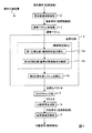
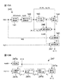
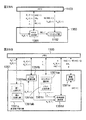
図1は、本発明の原理を備えた信号分離装置1の機能構成を例示したブロック図である。なお、後述のように、信号分離装置1は、例えば、公知のノイマン型のコンピュータに所定のプログラムを実行させることにより構成される。
信号分離装置1は、複数の信号源から発せられた源信号の混合からなる混合信号を当該源信号に分離する装置である。図1に例示するように、信号分離装置1は、周波数領域変換部2と、複素ベクトル生成部3と、正規化部4と、クラスタリング部5とを有している。ここで、正規化部4は、複素ベクトルが具備する特定の1つの要素を基準として当該複素ベクトルの各要素の偏角を正規化する第1正規化部4aと、第1正規化部4aで正規化された各要素の偏角を周波数に比例した値で除算する第2正規化部4bと、第2正規化部4bで正規化された各要素からなるベクトルのノルムを所定の値に正規化する第3正規化部4cとを有する。なお、第1正規化部4a及び第2正規化部4bにより、複素ベクトルの周波数依存性が排除される(周波数正規化)。Hereinafter, embodiments of the present invention will be described with reference to the drawings.
〔principle〕
First, the principle of the present invention will be described.
FIG. 1 is a block diagram illustrating a functional configuration of a
The
信号分離装置1によって信号分離処理を行う場合、まず、複数のセンサで観測された混合信号(時間領域の信号)が周波数領域変換部2に入力される。周波数領域変換部2は、短時間離散フーリエ変換等によって、複数のセンサで観測された混合信号(時間領域の信号)を、周波数領域の混合信号に変換する。次に、複素ベクトル生成部3が、当該周波数領域の混合信号を用い、複素数の要素からなる複素ベクトルを生成する。次に、正規化部4が、当該複素ベクトルを正規化し、当該複素ベクトルの周波数依存性を排除した正規化ベクトルを生成する。
When signal separation processing is performed by the
図1の例の正規化では、まず、第1正規化部4aが、時間周波数毎に、当該複素ベクトルが具備する特定の1つの要素を基準として当該複素ベクトルの各要素の偏角を正規化する。これにより、複素ベクトルの各要素の偏角は、源信号の位相や振幅に依存せず、各センサに対する信号源の相対位置や周波数のみに依存することになる(詳細は後述)。次に、第2正規化部4bが、第1正規化部4aで正規化された各要素の偏角を周波数に比例した値で除算する。これにより、各複素ベクトルの各要素の周波数依存性が排除され、複素ベクトルは、各センサに対する各信号源の相対位置のみに依存したものに正規化される。さらに、第3正規化部4cが、第2正規化部4bで正規化された各要素からなるベクトルのノルムを所定の値に正規化する。
In the normalization of the example of FIG. 1, first, the
次に、クラスタリング部5が、このような正規化が行われた正規化ベクトルのクラスタリングを行い、クラスタを生成する。これらのクラスタは、各センサに対する各信号源の相対位置のみに依存したものになる。分離信号生成部6は、これらのクラスタを利用して各種の信号分離処理を行い、周波数領域の分離信号を生成する。最後に、時間領域変換部が、周波数領域の分離信号を時間領域の分離信号に変換する。
上述のように、これらのクラスタを生成するために、各センサの厳密な位置情報を事前に取得しておく必要はない。また、これらのクラスタの生成には、全てのセンサでの観測信号の情報が用いられている。すなわち、本発明では、複数のセンサによる観測信号から得られた情報を容易かつ効率的に利用して信号分離処理を行うことができる。Next, the
As described above, in order to generate these clusters, it is not necessary to acquire accurate position information of each sensor in advance. In addition, information of observation signals from all sensors is used to generate these clusters. That is, in the present invention, signal separation processing can be performed using information obtained from observation signals from a plurality of sensors easily and efficiently.
なお、ノルムを正規化しなくても、クラスタリングの方法を工夫することにより、各センサに対する各信号源の相対位置のみに依存したクラスタを生成することは可能である。しかし、クラスタリングの処理を簡略化するため、第3正規化部4cによるノルムの正規化を行うことが望ましい。
以下、本発明の各実施の形態を詳細に説明する。
〔第1の実施の形態(「第1の本発明」の例)〕
まず、本発明における第1の実施の形態について説明する。Even if the norm is not normalized, it is possible to generate a cluster depending only on the relative position of each signal source with respect to each sensor by devising the clustering method. However, in order to simplify the clustering process, it is desirable to perform norm normalization by the
Hereinafter, each embodiment of the present invention will be described in detail.
First Embodiment (Example of “First Invention”)]
First, a first embodiment of the present invention will be described.
本形態は、上述の原理により、厳密なセンサ配置に係る情報の事前取得や煩雑な操作を必要とせずに正確にパーミュテーション問題を解決する形態である。なお、本形態では、後述する「基底ベクトル」が上述の「複素ベクトル」に相当する。
<ハードウェア構成>
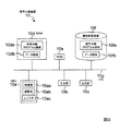
図2は、第1の実施の形態における信号分離装置10のハードウェア構成を例示したブロック図である。
図2に例示するように、この例の信号分離装置10は、CPU(Central Processing Unit)10a、入力部10b、出力部10c、補助記憶装置10f、RAM(Random Access Memory)10d、ROM(Read Only Memory)10e及びバス10gを有している。In this embodiment, the permutation problem is accurately solved without the need for prior acquisition of information related to strict sensor arrangement and complicated operations based on the above-described principle. In this embodiment, a “basis vector” described later corresponds to the “complex vector” described above.
<Hardware configuration>
FIG. 2 is a block diagram illustrating a hardware configuration of the
As illustrated in FIG. 2, a
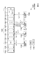
この例のCPU10aは、制御部10aa、演算部10ab及びレジスタ10ac有し、レジスタ10acに読み込まれた各種プログラムに従って様々な演算処理を実行する。また、この例の入力部10bは、データが入力される入力ポート、キーボード、マウス等であり、出力部10cは、データを出力する出力ポート、ディスプレイ等である。補助記憶装置10fは、例えば、ハードディスク、MO(Magneto-Optical disc)、半導体メモリ等であり、本形態の信号分離処理を実行するための信号分離プログラムを格納した信号分離プログラム領域10fa及びセンサで観測された時間領域の混合信号等の各種データが格納されるデータ領域10fbを有している。また、RAM10dは、例えば、SRAM (Static Random Access Memory)、DRAM (Dynamic Random Access Memory)等であり、信号分離プログラムが書き込まれる信号分離プログラム領域10da及び各種データが書き込まれるデータ領域10dbを有している。また、この例のバス10gは、CPU10a、入力部10b、出力部10c、補助記憶装置10f、RAM10d及びROM10eを通信可能に接続している。
The
<ハードウェアとソフトウェアとの協働>
この例のCPU10aは、読み込まれたOS(Operating System)プログラムに従い、補助記憶装置10fの信号分離プログラム領域10faに格納されている信号分離プログラムを、RAM10dの信号分離プログラム領域10daに書き込む。同様にCPU10aは、補助記憶装置10fのデータ領域10fbに格納されている時間領域の混合信号等の各種データをRAM10dのデータ領域10dbに書き込む。さらに、CPU10aは、この信号分離プログラムや各種データが書き込まれたRAM10d上のアドレスをレジスタ10acに格納する。そして、CPU10aの制御部10aaは、レジスタ10acに格納されたこれらのアドレスを順次読み出し、読み出したアドレスが示すRAM10d上の領域からプログラムやデータを読み出し、そのプログラムが示す演算を演算部10abに順次実行させ、その演算結果をレジスタ10acに格納していく。<Cooperation between hardware and software>
The
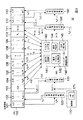
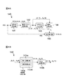
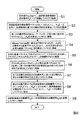
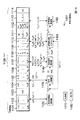
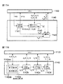
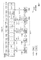
図3は、このようにCPU10aに信号分離プログラムが読み込まれることにより構成される信号分離装置10のブロック図の例示である。また、図4Aは、図3におけるパーミュテーション問題解決部140の詳細を例示したブロック図であり、図4Bは、図4Aの基底ベクトル正規化部142の詳細を例示したブロック図である。
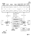
図3に例示するように、信号分離装置10は、メモリ100、周波数領域変換部120、分離行列算出部130、パーミュテーション問題解決部140、分離信号生成部150、時間領域変換部160及び制御部170を有している。また、この例のパーミュテーション問題解決部140は、逆行列算出部141(「複素ベクトル生成部」に対応)、基底ベクトル正規化部142(「正規化部」に対応)、クラスタリング部143、順列算出部144及び並び替え部145を有しており、基底ベクトル正規化部142は、周波数正規化部142a及びノルム正規化部142bを有している。また、周波数正規化部142aは、第1正規化部142aaと第2正規化部142abとを有している。さらに、制御部170は一時メモリ171を有している。FIG. 3 is an example of a block diagram of the
As illustrated in FIG. 3, the
ここでメモリ100及び一時メモリ171は、レジスタ10ac、補助記憶装置10fのデータ領域10fb或いはRAM10dのデータ領域10db等に相当する。また、周波数領域変換部120、分離行列算出部130、パーミュテーション問題解決部140、分離信号生成部150、時間領域変換部160及び制御部170は、CPU10aにOSプログラムや信号分離プログラムが読み込まれることにより構成されるものである。
なお、図3及び図4における破線の矢印は理論上の情報の流れを示し、実線の矢印は実際のデータの流れを示す。また、これらの図において制御部170に出入りするデータの流れに対応する矢印は省略してあり、図4における実際のデータの流れに対応する矢印も省略してある。Here, the
3 and FIG. 4, the broken-line arrows indicate the theoretical information flow, and the solid-line arrows indicate the actual data flow. Also, in these figures, arrows corresponding to the flow of data entering and leaving the
<処理>
次に、本形態の信号分離装置10の処理について説明する。なお、以下では、N個の源信号が混合され、M個のセンサで観測された状況を取り扱う。また、前処理において、各センサで観測された時間領域の混合信号xq(t)(q=1,...,M)がメモリ100の記憶領域101に格納され、信号の伝達速度c、M以下の自然数から選択された基準値Q(M個のセンサから選択された1つの基準センサの添字番号)及び実数dの各パラメータが記憶領域107に格納されているものとする。<Processing>
Next, processing of the
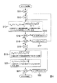
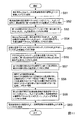
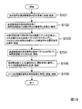
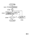
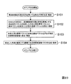
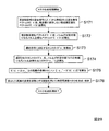
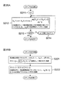
図5は、第1の実施の形態における信号分離装置10の処理の全体を説明するためのフローチャートである。以下、この図に沿って、本形態における信号分離装置10の処理を説明していく。
[周波数領域変換部120の処理]
まず、周波数領域変換部120において、メモリ100の記憶領域101から時間領域の混合信号xq(t)を読み出し、これらを短時間離散フーリエ変換等によって周波数毎の時系列の信号(「周波数領域の混合信号」と呼ぶ)Xq(f,τ)(q=1,...,M)に変換し、メモリ100の記憶領域102に格納する(ステップS1)。FIG. 5 is a flowchart for explaining the entire processing of the
[Processing of Frequency Domain Transformer 120]
First, the frequency
[分離行列算出部130の処理]
次に、分離行列算出部130において、メモリ100の記憶領域102から周波数領域の混合信号Xq(f,τ)を読み出す。周波数領域の混合信号Xq(f,τ)を読み出した分離行列算出部130は、これらからなる混合信号ベクトルX(f,τ)=[X1(f,τ),...,XM(f,τ)]Tを用い、独立成分分析(ICA)によって、周波数毎に第1の分離行列W(f)と分離信号ベクトルY(f,τ)=[Y1(f,τ),...,YN(f,τ)]Tとを算出する。そして、算出された第1の分離行列W(f)はメモリ100の記憶領域103に格納される(ステップS2)。[Processing of Separation Matrix Calculation Unit 130]
Next, the separation
ここで、分離行列算出部130において算出された第1の分離行列W(f)には、順序の任意性が含まれている。よって、以下のようにパーミュテーション問題解決部140において、第1の分離行列W(f)を順序の任意性を解決した第2の分離行列W’(f)に変更する。
[パーミュテーション問題解決部140の処理]
まず、逆行列算出部141において、メモリ100の記憶領域103から第1の分離行列W(f)を読み出し、そのムーア・ペンローズ(Moore-Penrose)型一般化逆行列W+(f)=[A1(f),...,AN(f)](M=Nの場合は逆行列W-1(f)に一致)を計算し、これを構成する基底ベクトルAp(f)=[A1p(f),...,AMp(f)]T (p=1,...,N)をメモリ100の記憶領域104に格納する(ステップS3)。
Here, the first separation matrix W (f) calculated by the separation
[Process of Permutation Problem Solving Unit 140]
First, the inverse
次に、基底ベクトル正規化部142において、メモリ100の記憶領域104から基底ベクトルAp(f)(p=1,...,N、f=0,fs/L,…,fs(L-1)/L)を読み出し、これらを正規化した正規化基底ベクトルAp''(f)を算出し、メモリ100の記憶領域106に格納する(ステップS4)。なお、基底ベクトル正規化部142は、全ての基底ベクトルAp(f)(p=1,...,N、f=0,fs/L,…,fs(L-1)/L)を正規化し、それらを周波数に依存せず、信号源の位置のみに依存する正規化基底ベクトルAp''(f)に正規化する。その結果、それらをクラスタリングした際に、各クラスタが各信号源に対応するようになる。この正規化を適切に行わないとクラスタが形成されない。また、本形態における正規化は周波数正規化とノルム正規化との二段階からなる。周波数正規化は、周波数正規化部142a(図4B)において、基底ベクトルを周波数に依存しない周波数正規化ベクトルに正規化するものである。ノルム正規化は、ノルム正規化部142bにおいて、周波数正規化ベクトルをノルムが規定値(この例では1)をとる正規化基底ベクトルに正規化するものである。これらの正規化処理の詳細については後述する。Next, in the basis
次に、クラスタリング部143において、メモリ100の記憶領域106から正規化基底ベクトルAp''(f)を読み出し、これらの正規化基底ベクトルAp''(f)をクラスタリングしてN個のクラスタCk(k=1,...,N)を生成し、各クラスタCkとそれらのセントロイド(中心ベクトル)ηkを特定する情報をメモリ100の記憶領域108,109に格納する(ステップS5)。このクラスタリングは、例えば、各クラスタCkの要素(正規化基底ベクトルAv''(f))と各クラスタCkのセントロイドηkとの間の二乗和Ukの総和UThen, the
次に、順列算出部144において、メモリ100の記憶領域106から正規化基底ベクトルAp''(f)を、記憶領域109から各クラスタCkのセントロイドηkをそれぞれ読み出す。そして、順列算出部144は、これらを用い、第1の分離行列W(f)の要素を並び替えるための順列Πf({1,2,…,N}から{1,2,…,N}への全単射な関数)を周波数f毎に算出し、メモリ100の記憶領域110に格納する(ステップS6)。なお、この順列Πfは、
Next, the
によって決定される。ここで式(13)におけるargminΠ・は、・を最小値化するΠを意味する。なお、式(13)に従って順列Πfを決定する手順としては、例えば、採り得るすべての順列Π(N!通り)に対して
Determined by. Here, argmin Π · in Equation (13) means Π that minimizes . As a procedure for determining the permutation Π f according to the equation (13), for example, for all possible permutations Π (N! Streets)
[順列Πf決定の具体例1]
信号源の数Nが3であり、ある周波数fにおける正規化基底ベクトルA1''(f),A2''(f),A3''(f)と各セントロイドη1,η2,η3との距離の自乗が、以下の表に示されるものであったとする。
[Specific example 1 of determining permutation Π f ]
The number N of signal sources is 3, normalized basis vectors A 1 ″ (f), A 2 ″ (f), A 3 ″ (f) at a certain frequency f, and the centroids η 1 , η 2. , Η 3 is the square of the distance as shown in the table below.
Πf:[1,2,3]→[2,3,1]
となる。なぜなら、
‖η1- Aπ(1)''(f)‖2=‖η1- A2''(f)‖2=0.1
‖η2- Aπ(2)''(f)‖2=‖η2- A3''(f)‖2=0.2
‖η3- Aπ(3)''(f)‖2=‖η3- A1''(f)‖2=0.15
という組合せが、
Π f : [1,2,3] → [2,3,1]
It becomes. Because
‖Η 1 -A π (1) '' (f) ‖ 2 = ‖η 1 -A 2 '' (f) ‖ 2 = 0.1
‖Η 2 -A π (2) '' (f) ‖ 2 = ‖η 2 -A 3 '' (f) ‖ 2 = 0.2
‖Η 3 -A π (3) '' (f) ‖ 2 = ‖η 3 -A 1 '' (f) ‖ 2 = 0.15
The combination of
しかし、この手順はNが大きくなると現実的ではない。そのため、その近似法として、順番に‖ηk-AΠ(k)''(f)‖2を最小値化するAΠ(k)''(f)を重複がないように選択していき、この選択されたAΠ(k)''(f)を正規化基底ベクトルAk''(f)に移す順列を順列Πfとする手順等を用いてもよい。以下、上述の[順列Πf決定の具体例1]と同じ条件に対し、この近似法を適用して順列Πfを決定する手順を示す。
However, this procedure is not practical as N increases. Therefore, as its approximation, sequentially ‖η k -A Π (k) ' ' (f) ‖ 2 A [pi to the minimum value of the (k) '' (f) will be chosen to no overlap of the Alternatively, a procedure such as a permutation をf for transferring the selected A Π (k) '' (f) to the normalized basis vector A k '' (f) may be used. A procedure for determining the permutation f f by applying this approximation method to the same conditions as those in [Specific example 1 of determining permutation f f ] will be described below.
[順列Πf決定の具体例2]
まず、上記の表1の場合、距離の自乗の最小値は0.1(正規化基底ベクトルA2''(f)と各セントロイドη1との距離の自乗)であるため、Π(1)=2を決定する。そして、正規化基底ベクトルA2''(f)と各セントロイドη1とに関連する行と列とを消すと以下のようになる。[Specific example 2 of determining permutation Π f ]
First, in the case of Table 1 above, since the minimum value of the square of the distance is 0.1 (the square of the distance between the normalized basis vector A 2 ″ (f) and each centroid η 1 ), Π (1 ) = 2. Then, erasing the row and column associated with the normalized basis vector A 2 ″ (f) and each centroid η 1 is as follows.
次に、並び替え部145において、メモリ100の記憶領域103から第1の分離行列W(f)を、記憶領域110から順列Πfを読み出す。そして、並び替え部145は、この第1の分離行列W(f)の行を順列Πfに従って並び替えた第2の分離行列W’(f)を生成してメモリ100の記憶領域111に格納する(ステップS7)。なお、第1の分離行列W(f)の行を順列Πfに従って並び替えるとは、上述のムーア・ペンローズ型一般化逆行列W+(f)における要素AΠ(k)''(f)からAk''(f)への並び替えに対応する並び替えを、第1の分離行列W(f)に対して行うことを意味する。すなわち、第1の分離行列W(f)の順列Πf(k)行目が第2の分離行列W’(f)のk行目になるように並び替える。上述の[順列Πf決定の具体例1,2]の場合、第1の分離行列W(f)の2,3,1行目が、それぞれ第2の分離行列W’(f)の1,2,3行目になる。
Next, the
[分離信号生成部150の処理]
その後、分離信号生成部150において、メモリ100の記憶領域102から周波数領域の混合信号Xq(f,τ)を、記憶領域111から第2の分離行列W’(f)を読み出す。そして、分離信号生成部150は、周波数領域の混合信号Xq(f,τ)からなる混合信号ベクトルX(f,τ)=[X1(f,τ),...,XM(f,τ)]Tと第2の分離行列W’(f)とを用い、分離信号ベクトル
Y(f,τ)=W’(f)・X(f,τ)
を算出し、これらの各要素である周波数領域の信号(「周波数領域の混合信号」と呼ぶ)Yp(f,τ)をメモリ100の記憶領域112に格納する(ステップS8)。[Processing of Separated Signal Generation Unit 150]
Thereafter, the separated signal generation unit 150 reads the mixed signal X q (f, τ) in the frequency domain from the
Y (f, τ) = W '(f) · X (f, τ)
, And a frequency domain signal (referred to as a “frequency domain mixed signal”) Y p (f, τ), which is each of these elements, is stored in the
[時間領域変換部160の処理]
最後に時間領域変換部160において、メモリ100の記憶領域112から周波数領域の分離信号Yp(f,τ)を読み出し、これを添え字p毎に(Yp(f,τ)毎に)短時間逆フーリエ変換等によって時間領域の分離信号yp(t)に変換し、これらの時間領域の分離信号yp(t)をメモリ100の記憶領域113に格納する(ステップS9)。
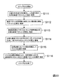
[正規化処理の詳細(ステップS4の詳細)]
次に、前述した基底ベクトル正規化部142における正規化処理の詳細(ステップS4の詳細)について説明する。[Processing of Time Domain Conversion Unit 160]
Finally, in the time
[Details of Normalization Processing (Details of Step S4)]
Next, details of the normalization processing in the above-described basis vector normalization unit 142 (details of step S4) will be described.
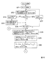
図6は、この正規化処理の詳細を説明するためのフローチャートである。
まず、制御部170(図3)においてパラメータpに1を代入し、これを一時メモリ171に格納する(ステップS11)。また、制御部170においてパラメータqに1を代入し、これを一時メモリ171に格納する(ステップS12)。次に、周波数正規化部142a(図4)において、メモリ100の記憶領域107から前述のパラメータd,c,Qを読み出し、一時メモリ171からパラメータp,qを読み出し、基底ベクトルAp(f)の要素Aqp(f)に対し、FIG. 6 is a flowchart for explaining the details of the normalization process.
First, 1 is substituted for the parameter p in the control unit 170 (FIG. 3), and this is stored in the temporary memory 171 (step S11). In addition, the
より詳細には、まず、周波数正規化部142aの第1正規化部142aaが、基底ベクトルAp(f)の特定の1つの要素AQp(f)を基準として当該基底ベクトルAp(f)の各要素Aqp(f)の偏角を、以下の演算によって正規化する。
More specifically, first, the first normalizing section 142aa of the
![]()
![]()
ここでp=Nでなければ、制御部170において、p+1の演算結果を新たなパラメータpの値とし、これを一時メモリ171に格納し(ステップS17)、処理をステップS12へ戻す。一方、p=Nであれば、制御部170においてパラメータpに1を代入し、これを一時メモリ171に格納し(ステップS18)、ノルム正規化部142bにおける処理を開始する。まず、ノルム正規化部142bにおいて、メモリ100の記憶領域105から周波数正規化ベクトルAp’(f)の各要素Aqp’(f)を読み出し、If p = N is not satisfied, the
次に、ノルム正規化部142bにおいて、一時メモリ171から周波数正規化ベクトルAp’(f)及びそのノルム‖Ap’(f)‖を読み出し、
Ap'' (f)=Ap’(f)/‖Ap’(f)‖ …(18)
の演算を行って正規化基底ベクトルAp'' (f)を求め、これをメモリ100の記憶領域106に格納する(ステップS20)。
Next, the
A p ″ (f) = A p ′ (f) / ‖A p ′ (f) ‖ (18)
The normalized basis vector A p ″ (f) is obtained by performing the above operation, and is stored in the
その後、制御部170において、一時メモリ171に格納されたパラメータpがp=Nを満たすか否かを判断する(ステップS21)。ここでp=Nでなければ、制御部170は、p+1の演算結果を新たなパラメータpの値とし、これを一時メモリ171に格納し(ステップS22)、ステップS19の処理に戻す。一方、p=Nであれば、制御部170は、ステップS4の処理を終了させる。
このように生成された正規化基底ベクトルAp''(f)は、周波数に依存せず、信号源の位置のみに依存するベクトルとなる。その結果、この正規化基底ベクトルAp''(f)はクラスタを形成することになる。以下にこの理由を説明する。Thereafter, the
The normalized basis vector A p ″ (f) generated in this way is a vector that does not depend on the frequency but depends only on the position of the signal source. As a result, this normalized basis vector A p ″ (f) forms a cluster. The reason for this will be described below.
[正規化基底ベクトルAp''(f)がクラスタを形成する理由]
基底ベクトルAp(f)の各要素Aqp(f)は、源信号pに対応する信号源kからセンサqヘの周波数応答Hqkに比例した(ある複素数スカラが掛かった)ものになっている。これらの複素数スカラは離散時間に応じて変化するが、源信号pとセンサqとに対応する複素数スカラと、源信号pとセンサQとに対応する複素数スカラとの相対値は、離散時間が変化しても一定である(周波数fが同じであれば)。すなわち、周波数fが同じであれば、源信号pとセンサqとに対応する複素数スカラの偏角と、源信号pとセンサQとに対応する複素数スカラの偏角との相対値は一定である。
[Reason why normalized basis vector A p ″ (f) forms a cluster]
Each element A qp (f) of the basis vector A p (f) is proportional to the frequency response H qk from the signal source k to the sensor q corresponding to the source signal p (a complex scalar is applied). Yes. These complex scalars change according to the discrete time, but the relative values of the complex scalars corresponding to the source signal p and the sensor q and the complex scalars corresponding to the source signal p and the sensor Q change in discrete time. Even if it is constant (if the frequency f is the same). That is, if the frequency f is the same, the relative value of the argument of the complex scalar corresponding to the source signal p and the sensor q and the argument of the complex scalar corresponding to the source signal p and the sensor Q are constant. .
前述のように、周波数正規化部142aの第1正規化部142aaは、基底ベクトルAp(f)の特定の1つの要素AQp(f)を基準として当該基底ベクトルAp(f)の各要素Aqp(f)の偏角を正規化する。これにより、上述の複素数スカラの位相に起因する不確定性を取り除き、源信号pとセンサqとに対応する基底ベクトルAp(f)の要素Aqp(f)の偏角を、源信号pと基準センサQ(基準値Qに対応)とに対応する基底ベクトルAp(f)の要素AQp(f)の偏角に対する相対値として表現する。なお、この場合、要素AQp(f)の偏角に対応する当該相対値は0と表現される。信号源kからセンサqヘの周波数応答を、反射や残響の無い直接波モデルで近似して考える。すると、上記の第1正規化部142aaにより正規化された偏角は、信号源kからセンサへの波の到達時間差と周波数fの双方に比例したものになる。ここでの到達時間差とは、信号源kからの波がセンサqに到達するまでの時間と、当該波が基準センサQに到達するまでの時間との時間差である。As described above, the first normalizing section 142aa of the
また、前述のように、第2正規化部142abは、第1正規化部142aaで正規化された各要素Aqp''' (f)の偏角を周波数fに比例した値で除算する。これにより、各要素Aqp''' (f)を、それらの偏角の周波数依存性を排除した各要素Aqp'(f)に正規化する。これにより、正規化された各要素Aqp'(f)は、直接波モデルに従えば、信号源kからセンサへの波の到達時間差のみに依存するものとなる。ここで、信号源kからセンサへの波の到達時間差は、信号源k,センサq,基準センサQの相対位置にのみ依存する。そのため、信号源k,センサq,基準センサQが同じであれば、周波数fが異なっても各要素Aqp'(f)の偏角は同一となる。従って、周波数正規化ベクトルAp' (f)は、周波数fには依存せず、信号源kの位置のみに依存する。Further, as described above, the second normalization unit 142ab divides the declination of each element A qp ″ (f) normalized by the first normalization unit 142aa by a value proportional to the frequency f. As a result, each element A qp ′ ″ (f) is normalized to each element A qp ′ (f) excluding the frequency dependence of the declination angle. Thereby, each normalized element A qp ′ (f) depends only on the arrival time difference of the wave from the signal source k to the sensor according to the direct wave model. Here, the difference in arrival time of waves from the signal source k to the sensor depends only on the relative positions of the signal source k, the sensor q, and the reference sensor Q. Therefore, if the signal source k, the sensor q, and the reference sensor Q are the same, the declination angle of each element A qp ′ (f) is the same even if the frequency f is different. Therefore, the frequency normalization vector A p ′ (f) does not depend on the frequency f, but only on the position of the signal source k.
そのため、周波数正規化ベクトルAp' (f)のノルムを正規化した正規化基底ベクトルAp''(f)のクラスタリングによって、同じ信号源毎に対応するクラスタが形成される。なお、実際の環境では、反射や残響などの影響により、直接波モデルは厳密には満たされないが、後述の実験結果に示すとおり十分に良い近似となっている。
次に、正規化基底ベクトルAp''(f)がクラスタを形成する理由を、モデルを用いて説明する。前述した式(1)に示されるインパルス応答hqk(r)を直接波(近距離場)混合モデルを用いて近似し、周波数領域で表すとTherefore, a cluster corresponding to the same signal source is formed by clustering of the normalized basis vector A p ″ (f) obtained by normalizing the norm of the frequency normalized vector A p ′ (f). In an actual environment, the direct wave model is not exactly satisfied due to the influence of reflection, reverberation, etc., but it is a sufficiently good approximation as shown in the experimental results described later.
Next, the reason why the normalized basis vector A p ″ (f) forms a cluster will be described using a model. Approximating the impulse response h qk (r) shown in the above equation (1) using a direct wave (near field) mixing model and expressing it in the frequency domain
また、独立成分分析(ICA)における順序の任意性とスケーリングの任意性とを考慮すると、基底ベクトルAp(f)と式(4)における信号源kから各センサへの周波数応答をまとめたベクトルHk(f)との間には、以下の関係が成り立つ。
In addition, considering the arbitrary order and the arbitrary scaling in independent component analysis (ICA), the vector that summarizes the frequency response from the signal source k to each sensor in the basis vector A p (f) and Equation (4). The following relationship holds with H k (f).
Ap(f)=εp・Hk(f), Aqp(f)=εp・Hqk(f) …(20)
ここで、εpはスケーリングの任意性を表現する複素スカラ値であり、添え字kとpが異なる可能性が順序の任意性を表現している。ここで、式(16)(18)(19)(20)より、
A p (f) = ε p · H k (f), A qp (f) = ε p · H qk (f) (20)
Here, ε p is a complex scalar value expressing the arbitraryness of scaling, and the possibility that the subscripts k and p are different expresses the arbitraryness of the order. Here, from the equations (16), (18), (19), and (20),
同様なことは、信号の減衰を考慮していない近距離場混合モデルでモデル化した場合にも言える。すなわち、前述した式(1)に示される畳み込み混合モデルを、減衰を無視した近距離場混合モデルで近似し、周波数領域で表すと
The same can be said for the case of modeling with a near-field mixed model that does not consider signal attenuation. That is, when the convolutional mixing model shown in the above equation (1) is approximated by a near-field mixing model that ignores attenuation, and expressed in the frequency domain,
![]()
![]()
さらに、近距離場混合モデルだけではなく、遠距離場混合モデルでも同様なことがいえる。すなわち、前述した式(1)に示される畳み込み混合モデルを遠距離場混合モデルで近似し、周波数領域で表すと
Furthermore, the same can be said for not only the near-field mixed model but also the far-field mixed model. In other words, when the convolutional mixing model shown in the above equation (1) is approximated by a far-field mixing model and expressed in the frequency domain,
![]()
![]()
となる。この場合も、正規化基底ベクトルAp''(f)の各要素Aqp''(f)は、周波数fからは独立であり、信号源kとセンサqの位置のみに依存している。
また、式(21)からパラメータdの値は、d>dmax/2であることが望ましく(dmaxは要素AQp(f)に対応する基準センサQと他のセンサとの最大距離を意味する。)、より好ましくはd≧dmaxであることが望ましく、さらにより好ましくはd=dmaxであることが望ましいことが分かる。以下、この理由について説明する。
It becomes. Also in this case, each element A qp ″ (f) of the normalized basis vector A p ″ (f) is independent of the frequency f and depends only on the positions of the signal source k and the sensor q.
Further, the value of the parameter d from equation (21), d> is preferably a d max / 2 (d max mean the maximum distance between the reference sensor Q and other sensors that correspond to elements A Qp (f) It is understood that d ≧ d max is more preferable, and d = d max is even more preferable. Hereinafter, this reason will be described.
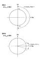
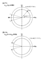
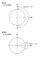
図7及び図8は、パラメータd毎の正規化基底ベクトルの要素Aqp''(f)とその偏角arg[Aqp''(f)]との関係を説明するための複素平面図である。なお、これらにおける横軸は実軸を縦軸は虚軸を示している。
図7Aはdmax/2≧dの場合における複素平面図である。ここで上述のdmaxの定義より、任意のq及びkに対しdqk-dQkの絶対値はdmax以下となる。よってdmax/2≧dの場合、(π/2)・(dqk-dQk)/d≦-π,(π/2)・(dqk-dQk)/d≧πと成り得る。その結果、式(21)で表されるAqp''(f)の偏角arg[Aqp''(f)]は、2πを超えるα1≦arg[Aqp''(f)]≦α2(α1≦-π、α2≧π)の範囲に分布する可能性がある。そのため、異なる正規化基底ベクトルの要素Aqp''(f)の偏角が一致する可能性があり、前述したクラスタリングにおいて、異なる正規化基底ベクトルAp''(f)を同じクラスタにクラスタリングしてしまう可能性がある。よって、d>dmax/2であることが望ましい。しかし、この偏角の重複範囲に対応する正規化基底ベクトルAp''(f)のサンプルが存在しないならばdmax/2≧dとしても問題はない。FIG. 7 and FIG. 8 are complex plan views for explaining the relationship between the element A qp ″ (f) of the normalized basis vector for each parameter d and the argument arg [A qp ″ (f)]. is there. In these figures, the horizontal axis represents the real axis and the vertical axis represents the imaginary axis.
FIG. 7A is a complex plan view when d max / 2 ≧ d. Here, from the above definition of d max , the absolute value of d qk -d Qk is less than or equal to d max for any q and k. Therefore, when d max / 2 ≧ d, (π / 2) · (d qk −d Qk ) / d ≦ −π and (π / 2) · (d qk −d Qk ) / d ≧ π can be obtained. As a result, equation (21) A qp 'represented by' deflection angle (f) arg [A qp ' ' (f)] is greater than 2π α 1 ≦ arg [A qp '' (f)] ≦ There is a possibility of distribution in the range of α 2 (α 1 ≦ −π, α 2 ≧ π). Therefore, there is a possibility that the declination angles of elements A qp ″ (f) of different normalized basis vectors match. In the clustering described above, different normalized basis vectors A p ″ (f) are clustered into the same cluster. There is a possibility that. Therefore, it is desirable that d> d max / 2. However, if there is no sample of the normalized basis vector A p ″ (f) corresponding to this overlapping range of declination, there is no problem even if d max / 2 ≧ d.
図7Bはdmax/2<d<dmaxの場合における複素平面図である。この場合、-π<(π/2)・(dqk-dQk)/d<-π/2,π/2<(π/2)・(dqk-dQk)/d<πと成り得る。その結果、式(21)で表されるAqp''(f)の偏角arg[Aqp''(f)]は、β1≦arg[Aqp''(f)]≦β2(-π<β1<-π/2、π/2<β2<π)の範囲に分布する可能性がある。そのため、-π<arg[Aqp''(f)]<-π/2及びπ/2<arg[Aqp''(f)]<πの範囲において、異なる周波数正規化ベクトル要素間の偏角の差の増加に伴い、これらの周波数正規化ベクトル要素間の距離が単調増加しないこともありうる。これは、前述したクラスタリングの精度を低下させる可能性がある。よってd≧dmaxであることがより望ましい。FIG. 7B is a complex plan view in the case of d max / 2 <d <d max . In this case, −π <(π / 2) · (d qk −d Qk ) / d <−π / 2, π / 2 <(π / 2) · (d qk −d Qk ) / d <π obtain. As a result, equation (21) A qp 'represented by' deflection angle (f) arg [A qp ' ' (f)] is, β 1 ≦ arg [A qp '' (f)] ≦ β 2 ( There is a possibility of distribution in the range of −π <β 1 <−π / 2, π / 2 <β 2 <π). Therefore, in the range of −π <arg [A qp ″ (f)] <− π / 2 and π / 2 <arg [A qp ″ (f)] <π, the deviation between different frequency normalized vector elements is As the angle difference increases, the distance between these frequency normalized vector elements may not increase monotonically. This may reduce the accuracy of the clustering described above. Therefore, it is more desirable that d ≧ d max .
図8Aはd=dmaxの場合における複素平面図であり、図8Bはd>dmaxの場合における複素平面図である。ここでd>dmaxの場合、-π/2<(π/2)・(dqk-dQk)/d<0,0<(π/2)・(dqk-dQk)/d<π/2と成り得る。その結果、式(21)で表されるAqp''(f)の偏角arg[Aqp''(f)]は、図8Bに示すように、γ1≦arg[Aqp''(f)]≦γ2(-π/2<γ1<0、0<γ2<π/2)の範囲に分布する。そして、dが大きくなればなるほどその分布範囲は狭くなっていき、狭い範囲にクラスタが密集していく。これは、前述したクラスタリングの精度を低下させる。FIG. 8A is a complex plan view in the case of d = d max , and FIG. 8B is a complex plan view in the case of d> d max . Here, when d> d max , −π / 2 <(π / 2) · (d qk −d Qk ) / d <0, 0 <(π / 2) · (d qk −d Qk ) / d < It can be π / 2. As a result, equation (21) A qp 'represented by' deflection angle (f) arg [A qp ' ' (f)] , as shown in FIG. 8B, γ 1 ≦ arg [A qp '' ( f)] ≦ γ 2 (−π / 2 <γ 1 <0, 0 <γ 2 <π / 2). As d increases, the distribution range becomes narrower, and clusters are concentrated in a narrow range. This reduces the accuracy of the clustering described above.
これに対し、d=dmaxである場合、-π/2≦(π/2)・(dqk-dQk)/d<0,0<(π/2)・(dqk-dQk)/d≦π/2と成り得る。その結果、式(21)で表されるAqp''(f)の偏角arg[Aqp''(f)]は図8Aに示すように-π/2≦arg[Aqp''(f)]≦π/2の範囲に分布する。この場合、周波数正規化ベクトルの要素間における偏角の差の増加に対して、それらの距離も単調増加するという関係を維持しつつ、できるだけ広い範囲にクラスタを分散させることができる。その結果、一般的にクラスタリングの精度を向上させることができる。
〔第2の実施の形態(「第1の本発明」の例)〕
次に本発明における第2の実施の形態について説明する。On the other hand, when d = d max , −π / 2 ≦ (π / 2) · (d qk −d Qk ) / d <0, 0 <(π / 2) · (d qk −d Qk ) / d ≦ π / 2. As a result, equation (21) A qp 'represented by' deflection angle (f) arg [A qp ' ' (f)] is - [pi] / 2 ≦ arg as shown in Figure 8A [A qp '' ( f)] is distributed in the range of ≦ π / 2. In this case, it is possible to disperse the clusters over as wide a range as possible while maintaining the relationship that the distance increases monotonously with respect to the increase in the difference in declination between the elements of the frequency normalization vector. As a result, generally the accuracy of clustering can be improved.
[Second Embodiment (Example of "First Invention")]
Next, a second embodiment of the present invention will be described.
第1の実施の形態では、基底ベクトルから得られる情報によりパーミュテーション問題を解決したが、本形態では、これに特開2004−145172号公報や「H. Sawada, R. Mukai, S. Araki, S. Makino, "A Robust and Precise Method for Solving the Permutation Problem of Frequency-Domain Blind Source Separation," IEEE Trans. Speech and Audio processing, vol. 12, no. 5, pp. 530-538, Sep. 2004.(以下「参考文献」と呼ぶ)」で示されているような分離信号のエンベロープの情報を統合することで、より精度よくパーミュテーション問題を解決する。なお、これらの文献では、基底ベクトルの代わりに信号源の方向に関する情報が利用されている。 In the first embodiment, the permutation problem is solved by the information obtained from the basis vectors. However, in this embodiment, Japanese Patent Application Laid-Open No. 2004-145172 and “H. Sawada, R. Mukai, S. Araki” , S. Makino, "A Robust and Precise Method for Solving the Permutation Problem of Frequency-Domain Blind Source Separation," IEEE Trans. Speech and Audio processing, vol. 12, no. 5, pp. 530-538, Sep. 2004 (Hereinafter referred to as “references”) ”, the permutation problem can be solved more accurately by integrating the envelope information of the separated signal. In these documents, information on the direction of the signal source is used instead of the basis vector.
以下では、第1の実施の形態との相違点を中心に説明を行い、これと共通する事項については説明を省略する。
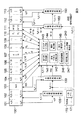
<構成>
図9は、第2の実施の形態における信号分離装置200のブロック図の例示である。なお、本形態の信号分離装置200もCPU10a(図2)に信号分離プログラムが読み込まれることにより構成されるものである。また、図10Aは、図9におけるパーミュテーション問題解決部240の詳細を例示したブロック図であり、図10Bは、図10Aの順列修正部247の詳細を例示したブロック図である。なお、図9及び図10において第1の実施の形態と共通する部分については第1の実施の形態と同じ符号を付した。また、図9及び図10における破線の矢印は理論上の情報の流れを示し、実線の矢印は実際のデータの流れを示す。また、これらの図において制御部170に出入りするデータの流れに対応する矢印は省略してあり、図10における実際のデータの流れに対応する矢印も省略してある。Below, it demonstrates centering around difference with 1st Embodiment, and abbreviate | omits description about the matter which is common to this.
<Configuration>
FIG. 9 is an example of a block diagram of a
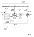
本形態の第1の実施の形態のとの相違点は、主にパーミュテーション問題解決部240の構成である。すなわち、本形態のパーミュテーション問題解決部240は、第1の実施の形態のパーミュテーション問題解決部140に、順列評価部246と順列修正部247とを付加したものとなっている(図9,図10A)。なお、順列評価部246は、周波数毎に順列の信頼度を評価するものであり、順列修正部247は、順列の信頼度が低いと評価された周波数に対し、分離信号のエンベロープを用いて新たな順列を算出するものである。また、順列修正部247は、判定部247aと分離信号生成部247bとエンベロープ算出部247cと順列再算出部247dと再並び替え部247eを有している(図10B)。また、本形態では、順列算出部144と順列修正部247とによって請求項4の「順列算出部」を構成している。
The difference of the present embodiment from the first embodiment is mainly the configuration of the permutation
<処理>
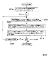
図11は、第2の実施の形態における信号分離装置200の処理の全体を説明するためのフローチャートである。以下、この図に沿って、本形態における信号分離装置200の処理を説明していく。
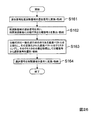
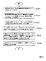
ステップS51からS57の処理は、第1の実施の形態におけるステップS1からS7までと同じであるため説明を省略する。本形態では、このステップS57の処理の後に、順列評価部246において、周波数毎に順列Πfの信頼度を評価し、順列Πfの信頼度が低いと評価された周波数に対し、分離信号のエンベロープを用いて順列Πf’を算出し、この周波数のみについて第2の分離行列W’(f)の行を順列Πf’に従って並び替えて第3の分離行列W''(f)を生成し、メモリ100の記憶領域110に格納する(ステップS58)。なお、この処理の詳細については後述する。<Processing>
FIG. 11 is a flowchart for explaining the entire processing of the
Since the process of step S51 to S57 is the same as that of step S1 to S7 in 1st Embodiment, description is abbreviate | omitted. In this embodiment, after the processing of step S57, the
その後、分離信号生成部150において、メモリ100の記憶領域102から周波数領域の混合信号Xq(f,τ)を、記憶領域111から第3の分離行列W''(f)を読み出す。そして、分離信号生成部150は、周波数領域の混合信号Xq(f,τ)からなる混合信号ベクトルX(f,τ)=[X1(f,τ),...,XM(f,τ)]Tと第3の分離行列W''(f)とを用い、分離信号ベクトル
Y(f,τ)=W''(f)・X(f,τ)
を算出し、周波数領域の分離信号Yp(f,τ)をメモリ100の記憶領域112に格納する(ステップS59)。Thereafter, the separation signal generation unit 150 reads the mixed signal X q (f, τ) in the frequency domain from the
Y (f, τ) = W '' (f) ・ X (f, τ)
And the frequency domain separation signal Y p (f, τ) is stored in the
最後に時間領域変換部160において、メモリ100の記憶領域112から周波数領域の分離信号Yp(f,τ)を読み出し、これを添え字p毎に時間領域の分離信号yp(t)に変換し、これらの時間領域の分離信号yp(t)をメモリ100の記憶領域113に格納する(ステップS60)。
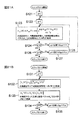
[ステップS58の処理の詳細」
図12及び図13は、図11におけるステップS58の例を説明するためのフローチャートである。以下、このフローチャートに沿ってステップS58の詳細を説明していく。Finally, the time
[Details of processing in step S58]
12 and 13 are flowcharts for explaining an example of step S58 in FIG. Details of step S58 will be described below along this flowchart.
まず、制御部170においてパラメータfに0を代入し、集合Fを空集合とし、これらを示す情報を一時メモリ171に格納する(ステップS71)。次に、順列評価部246において、メモリ100の記憶領域110に格納された順列Πfの信頼度を周波数毎に評価し、その評価結果trust(f)を一時メモリ171に格納する(ステップS72)。ここで、順列Πfの信頼性が高いとは、例えば、正規化基底ベクトルAp''(f)が、それぞれに対応するセントロイドηkに十分近いということである。また、正規化基底ベクトルAp''(f)が、それぞれに対応するセントロイドηkに十分近いかどうかは、例えば、正規化基底ベクトルAp''(f)とセントロイドηkとの距離がクラスタCkの分散Uk/|Ck|より小さいかどうか、すなわち、
Uk/|Ck|>‖ηk-AΠ(k)''(f)‖2 …(26)
により判定できる。よって、このステップでは、例えばまず、順列評価部246において、メモリ100の記憶領域105から正規化基底ベクトルAp''(f)を、記憶領域109からセントロイドηkを、記憶領域110から順列Πfをそれぞれ読み出す。そして、順列評価部246は、周波数f毎に、式(26)を満たすか否かを判断し、満たす場合にはtrust(f)=1を、満たさない場合にはtrust(f)=0を出力し、一時メモリ171に格納する。First, the
U k / | C k |> ‖η k -A Π (k) '' (f) ‖ 2 … (26)
Can be determined. Therefore, in this step, for example, first, in the
次に、順列修正部247の判定部247aが、一時メモリ171から周波数f毎に評価結果trust(f)を読み出し、trust(f)=1であるか否かを判断する(ステップS73)。ここで、trust(f)=0である場合、そのままステップS76の処理に進む。一方、trust(f)=1である場合、制御部170において、集合Fと{f}の和集合を新たな集合Fとして一時メモリ171に格納し(ステップS74)、再並び替え部247eにおいて、この周波数fにおける第2の分離行列W'(f)を第3の分離行列W''(f)としてメモリ100の記憶領域111に格納し(ステップS75)、ステップS76に進む。
Next, the
ステップS76では、制御部170において、一時メモリ171に格納されたパラメータfの値がf=(L-1)fs/Lを満たすか否かを判断し(ステップS76)、これを満たさなければf+fs/Lの演算結果を新たなパラメータfの値として(ステップS77)一時メモリ171に格納し、ステップS72に戻る。
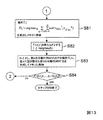
一方、f=(L-1)fs/Lを満たす場合、分離信号生成部247bにおいて、集合Fに属しない周波数fを1つ選択する。そして、分離信号生成部247bは、この周波数fとその近傍であって集合Fに属する全ての周波数g(g∈F,|g-f|≦δ,δは定数)とに対し、メモリ100の記憶領域102から周波数領域の混合信号X(f,τ)=[X1(f,τ),…,XM(f,τ)]T, X(g,τ)=[X1(g,τ),…,XM(g,τ)]Tを読み出し、記憶領域111から第2の分離行列W’(f),W’(g)を読み出し、
Y(f,τ)=W’(f)・X(f,τ)
Y(g,τ)=W’(g)・X(g,τ)
によって分離信号Y(f,τ)=[Y1(f,τ),…,YN(f,τ)]T, Y(g,τ)=[Y1(g,τ),…,YN(g,τ)]Tを算出して一時メモリ171に格納する(ステップS78)。In step S76, the
On the other hand, when f = (L−1) f s / L is satisfied, the separated
Y (f, τ) = W '(f) · X (f, τ)
Y (g, τ) = W '(g) · X (g, τ)
, Y (f, τ) = [Y 1 (f, τ),..., Y N (f, τ)] T , Y (g, τ) = [Y 1 (g, τ),. N (g, τ)] T is calculated and stored in the temporary memory 171 (step S78).
次に、エンベロープ算出部247cにおいて、一時メモリ171から全ての周波数領域の分離信号Yp(f,τ), Yp(g,τ)を読み出し、これらのエンベロープ
vp f(τ)=|Yp(f,τ)|
vp g(τ)=|Yp(g,τ)|
を算出して一時メモリ171に格納する(ステップS79)。
そして、順列再算出部247dにおいて、周波数の差δ以下の近傍における相関corの和の最大値Next, in the
v p f (τ) = | Y p (f, τ) |
v p g (τ) = | Y p (g, τ) |
Is calculated and stored in the temporary memory 171 (step S79).
Then, in the
![]()
cor(Φ,Ψ)=(<Φ,Ψ>-<Φ>・<Ψ>)/(σΦ・σΨ)
ただし、<ζ>はζの時間平均であり、σΦはΦの標準偏差である。 ![]()
cor (Φ, Ψ) = (<Φ, Ψ>-<Φ> ・ <Ψ>) / (σ Φ・ σ Ψ )
Where <ζ> is the time average of ζ and σΦ is the standard deviation of Φ .
また、順列再算出部247dにおいて、この相関corの和を最大値化する順列
In the
次に、制御部170において集合Fと{ζ}(ζ=argmaxfRf)との和集合を新たな集合Fとして一時メモリ171に格納する(ステップS82)。そして、再並び替え部247eにおいて、f=ζとし、第2の分離行列W’(f)の行を順列Πf’に従って並び替えた第3の分離行列W''(f)を生成し、これをメモリ100の記憶領域111に格納する(ステップS83)。
Next, the
次に、制御部170において、一時メモリ171に格納された集合Fが全ての離散化された周波数f=0,fs/L,…,fs(L-1)/Lの要素を有するか否かを判断する(ステップS84)。ここで、集合Fが全ての離散化された周波数f=0,fs/L,…,fs(L-1)/Lの要素を有しないのであれば、制御部170は、処理をステップS78に戻す。一方、集合Fが全ての離散化された周波数f=0,fs/L,…,fs(L-1)/Lの要素を有するのであれば、制御部170は、ステップS58の処理を終了させる。
なお、以上の方法を用いず、前述した特開2004−145172号公報や「参考文献」に記載されたその他の方法を用い、ステップS58の処理を実行してもよい。Next, in the
In addition, you may perform the process of step S58 not using the above method but using the other method described in Unexamined-Japanese-Patent No. 2004-145172 and the "reference literature" mentioned above.
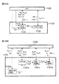
<実験結果>
次に、上述した第1の実施の形態及び第2の実施の形態による音源分離実験結果を示す。
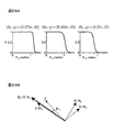
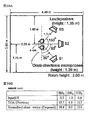
[実験結果1]
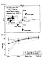
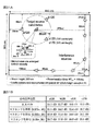
1つ目の実験は不規則なセンサ配置によるものである。実験条件は図14Aに示す通りである。ここでは4つの無指向性マイクを不規則に配置したものを用いたが、これらの配置情報としては、マイク間隔の上限が4cmであるということだけを信号分離装置に与えた。音源の数は3つであり、3秒間の英語の音声をスピーカから流した。結果を図14BにSIR(signal-to-interference ratio)によって示す。大きいSIRほど分離性能が良いことを示す。ここではパーミュテーション問題を解決する4種類の手法に関して結果を比較した。Envは分離信号のエンベロープ|Yp(f,τ)|の情報のみを用いたもの、Basisは正規化基底ベクトルAp''(f)のクラスタリングによるもの(第1の実施の形態の手法)、Basis+Envはそれら2種類の情報を統合してより精度良く問題を解決したもの(第2の実施の形態の手法)、Optimalは源信号skとインパルス応答hqk(r)を知って得た最適な順列によるものである。<Experimental result>
Next, the sound source separation experiment results according to the first embodiment and the second embodiment described above will be shown.
[Experimental result 1]
The first experiment is due to irregular sensor placement. Experimental conditions are as shown in FIG. 14A. Here, four omnidirectional microphones arranged irregularly were used. However, as the arrangement information, only that the upper limit of the microphone interval is 4 cm is given to the signal separation device. The number of sound sources was three, and English sound for 3 seconds was played from the speaker. The results are shown in FIG. 14B by SIR (signal-to-interference ratio). Larger SIR indicates better separation performance. Here, the results were compared for four methods for solving the permutation problem. Env uses only the information of the separated signal envelope | Y p (f, τ) |, and Basis uses clustering of normalized basis vectors A p ″ (f) (the method of the first embodiment). , Basis + Env is a solution that solves the problem more accurately by integrating these two types of information (the method of the second embodiment), Optimal knows the source signal s k and the impulse response h qk (r) This is due to the optimal permutation obtained.
結果を考察すると、Envだけでは性能にばらつきがあるが、第1の実施の形態のBasisはそれだけで十分な分離性能を得ている。また、双方を統合した第2の実施の形態のBasis+Envの結果はほぼOptimalに近い。このように不規則なセンサ配置を用いた場合でも、本発明により、周波数領域でのブラインド信号分離が高性能で達成された。
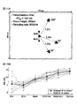
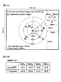
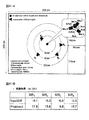
[実験結果2]
2つ目の実験は規則的なセンサ配置によるものである。実験条件は図15Aに示す通りである。3つの無指向性マイクを直線状に4cm間隔で配置した。音源の数は同様に3つであり、3秒問の英語の音声をスピーカから流した。結果を図15Bに示す。この実験では、従来技術として示した信号源の位置に関する推定値をクラスタリングする方法も比較対象とし、6種類の手法に関して結果を比較した。DOAは信号の到来方向(DOA:direction-of-arrival)の推定値のみでパーミュテーション問題を解決したもの、DOA+Envはさらに分離信号のエンベロープ情報を統合したものある。Considering the results, performance varies with Env alone, but Basis of the first embodiment obtains sufficient separation performance by itself. Further, the result of Basis + Env in the second embodiment in which both are integrated is almost close to Optimal. Even when such an irregular sensor arrangement is used, blind signal separation in the frequency domain is achieved with high performance according to the present invention.
[Experimental result 2]
The second experiment is due to regular sensor placement. The experimental conditions are as shown in FIG. 15A. Three omnidirectional microphones were linearly arranged at 4 cm intervals. Similarly, the number of sound sources was three, and English sound of 3 seconds was played from the speaker. The results are shown in FIG. 15B. In this experiment, the method of clustering the estimated values related to the position of the signal source shown as the prior art was also compared, and the results of the six types of methods were compared. DOA solves the permutation problem using only the estimated direction-of-arrival (DOA), and DOA + Env further integrates the envelope information of the separated signal.
従来技術であるDOA及びDOA+Envと、本発明であるBasis及びBasis+Envの結果を比較すると、従来手法が適用可能である規則的なセンサ配置に対しても、総じて本発明により結果が改善されていることがわかる。なお、演算量に関しては、従来技術とほぼ同等であった。
<第1,2の実施の形態の特徴>
以上より、上述した第1,2の実施の形態の特徴をまとめると以下のようになる。
(1)センサの配置情報を厳密に知る必要がなく、ある基準センサから他のセンサヘの距離の上限のみを知ればよいため、不規則なセンサ配置を採用でき、さらに位置をキャリブレーションする必要が無い。(2)基底ベクトルから得られる情報をすべて用いてクラスタリングを行うためパーミュテーション問題をより正確に解決することができ、信号分離の性能が向上する。Comparing the results of the prior art DOA and DOA + Env with the present invention Basis and Basis + Env, the results of the present invention are generally improved even for regular sensor arrangements to which the conventional method can be applied. I understand that. Note that the amount of calculation was almost the same as that of the prior art.
<Characteristics of the first and second embodiments>
From the above, the characteristics of the first and second embodiments described above are summarized as follows.
(1) Since it is not necessary to know the sensor placement information strictly, it is only necessary to know the upper limit of the distance from one reference sensor to another sensor, so irregular sensor placement can be adopted and the position needs to be calibrated. No. (2) Since the clustering is performed using all the information obtained from the basis vectors, the permutation problem can be solved more accurately, and the signal separation performance is improved.
なお、本発明は上述の実施の形態に限定されるものではない。例えば、上述した各実施の形態では、一般化行列としてムーア・ペンローズ型一般化逆行列を用いたが他の一般化行列を利用する形態でもよい。
また、第1の実施の形態では、周波数正規化部142aの第1正規化部142aaが、基底ベクトルAp(f)の特定の1つの要素AQp(f)を基準とし、式(15)によって当該基底ベクトルAp(f)の各要素Aqp(f)の偏角を正規化することとした。しかし、例えば、以下のような式に従って、第1正規化部142aaが、基底ベクトルAp(f)の特定の1つの要素AQp(f)を基準として、当該基底ベクトルAp(f)の各要素Aqp(f)の偏角を正規化する構成であってもよい。The present invention is not limited to the embodiment described above. For example, in each of the above-described embodiments, the Moore-Penrose type generalized inverse matrix is used as the generalized matrix, but another generalized matrix may be used.
In the first embodiment, the first normalization unit 142aa of the
また、周波数正規化部142aが式(14)の代わりに、
In addition, the
また、上述の実施の形態では、ノルム正規化部142bにおいてノルムが1になるような正規化を行ったが、ノルムが1以外の規定値となるように正規化を行ってもよい。さらに、ノルム正規化部142bを設けず、ノルム正規化を行わない構成であってもよい。この場合、クラスタリング部143は、周波数正規化ベクトルAp’(f)のクラスタリングを行うことになる。しかし、周波数正規化ベクトルAp’(f)は、ノルムが統一されていない。そこで、この場合のクラスタリング基準は、ベクトルがノルムを含めて似ているかどうかではなく、ベクトルの方向のみが似ているかどうかになる。これは、類似度を用いた評価になる。類似度の1つとしてコサイン距離
cosθ=|Ap’H(f)・ηk|/(‖Ap’(f)‖・‖ηk‖)
を例示できる。ここでθは、周波数正規化ベクトルAp’(f)と、セントロイドηkのベクトルとがなす角度である。コサイン距離を用いる場合、クラスタリング部143は、コサイン距離の総和
In the above-described embodiment, normalization is performed so that the norm is 1 in the
cosθ = | A p ' H (f) · η k | / (‖A p ' (f) ‖ ・ ‖η k ‖)
Can be illustrated. Here, θ is an angle formed by the frequency normalization vector A p ′ (f) and the vector of the centroid η k . When using the cosine distance, the
さらに、上記の第2の実施の形態では、周波数毎に順列の信頼度を評価し、順列の信頼度が低いと評価された周波数に対し、分離信号のエンベロープを用いて新たな順列を算出することとした。しかし、分離信号のエンベロープとクラスタの中心ベクトルと正規化基底ベクトルとを一度に統合して順列を算出することとしてもよい。
Furthermore, in the second embodiment, the permutation reliability is evaluated for each frequency, and a new permutation is calculated using the envelope of the separation signal for the frequency evaluated as having low permutation reliability. It was decided. However, the permutation may be calculated by integrating the envelope of the separated signal, the center vector of the cluster, and the normalized basis vector at a time.
また、まず分離信号のエンベロープを用いて順列を算出し、その順列の信頼度を周波数毎に評価し、信頼度が低いと評価された周波数に対して、第1の実施の形態の手法を適用して新たな順列を算出することとしてもよい。
さらに、上記の第2の実施の形態では、第2の分離行列W’(f)を用いて分離信号のエンベロープを算出したが、第1の分離行列W(f)或いはその行を並び替えた分離行列を用いてエンベロープを算出する構成としてもよい。
また、パラメータdは、全てのセンサqに対して同一であってもよいし、各センサqに対応して複数の値を設定しておいてもい。例えば、基準センサとセンサqとの距離を、それぞれのセンサqに対応するパラメータdの値としてもよい。First, a permutation is calculated using the envelope of the separated signal, the reliability of the permutation is evaluated for each frequency, and the method of the first embodiment is applied to the frequency evaluated as having low reliability. Then, a new permutation may be calculated.
Furthermore, in the second embodiment, the envelope of the separation signal is calculated using the second separation matrix W ′ (f). However, the first separation matrix W (f) or its row is rearranged. It is good also as a structure which calculates an envelope using a separation matrix.
The parameter d may be the same for all the sensors q, or a plurality of values may be set for each sensor q. For example, the distance between the reference sensor and the sensor q may be the value of the parameter d corresponding to each sensor q.
〔第3の実施の形態(「第2の本発明」の例)〕
次に、本発明における第3の実施の形態について説明する。
本形態は、前述の原理を用い、目的信号の方向に関する情報を知ることなく、複数の信号源から発せられた信号が混合された混合信号から目的信号を抽出する形態である。
<構成>
本形態の信号分離装置も、第1の実施の形態と同様、公知のノイマン型のコンピュータに信号分離プログラムが読み込まれることにより構成される。図16は、第3の実施の形態における信号分離装置1001の構成を例示したブロック図である。[Third Embodiment (Example of "Second Invention")]
Next, a third embodiment of the present invention will be described.
In this embodiment, the target signal is extracted from a mixed signal obtained by mixing signals emitted from a plurality of signal sources without knowing information on the direction of the target signal, using the principle described above.
<Configuration>
Similarly to the first embodiment, the signal separation device of this embodiment is configured by reading a signal separation program into a known Neumann computer. FIG. 16 is a block diagram illustrating a configuration of a
この図に例示するように、信号分離装置1001は、記憶領域1101〜1114を有するメモリ1100、周波数領域変換部1120、信号分離部1130、目的信号選択部1140、時間周波数マスキング部1150(「分離信号生成部」に相当)、時間領域変換部1160、制御部1170及び一時メモリ1180を有する。ここでメモリ1100及び一時メモリ1180は、例えば、レジスタ10ac、補助記憶装置10fのデータ領域10fb或いはRAM10dのデータ領域10db(図2)の少なくとも一部に相当するが、特にこれに限定されない。また、周波数領域変換部1120、信号分離部1130、目的信号選択部1140、時間周波数マスキング部1150、時間領域変換部1160、制御部1170及び一時メモリ1180は、例えば、CPU10a(図2)にOSプログラムや信号分離プログラムが読み込まれることにより構成されるものである。
As illustrated in this figure, the
図17Aは、図16における目的信号選択部1140の詳細構成を例示したブロック図であり、図17Bは、図17Aにおける基底ベクトルクラスタリング部1142の詳細構成を例示したブロック図である。
これらの図に例示するように、目的信号選択部1140は、逆行列算出部1141(「複素ベクトル生成部」に対応)、基底ベクトルクラスタリング部1142及び選択部1143を有している。また、基底ベクトルクラスタリング部1142は、周波数正規化部1142a(「正規化部」を構成)、ノルム正規化部1142b(「正規化部」を構成)、クラスタリング部1142c及び分散判定部1142dを有している。また、周波数正規化部1142aは、第1正規化部1142aa及び第2正規化部1142abを有している。17A is a block diagram illustrating a detailed configuration of the target
As illustrated in these drawings, the target
図18Aは、図16における時間周波数マスキング部1150の詳細構成を例示したブロック図であり、図18Bは、図18Aにおけるマスク生成部1151の詳細を例示したブロック図である。
これらの図に例示するように、時間周波数マスキング部1150は、マスク生成部1151及びマスキング部1152を有している。また、マスク生成部1151は、白色化行列生成部1151a、白色化部1151b、角度計算部1151c及び関数演算部1151dを有している。18A is a block diagram illustrating the detailed configuration of the time-
As illustrated in these drawings, the time-
なお、図16〜図18における実線の矢印は実際のデータの流れを示し、破線の矢印は理論上の情報の流れを示すが、制御部1170及び一時メモリ1180に出入りするデータの流れは省略してある。また、信号分離装置1001は制御部1170の制御のもと各処理を実行する。また、特に示さない限り、制御部1170は、必要なデータを一時メモリ1180に読み書きしながら各処理を実行していく。
<処理>
次に、本形態における信号分離装置1001の処理について説明する。Note that the solid arrows in FIGS. 16 to 18 show the actual data flow, and the broken arrows show the theoretical information flow, but the data flow to and from the
<Processing>
Next, processing of the
空間内にN個の信号源k(k∈{1,2,...,N})が存在し、それらの信号sk(t)(tはサンプリング時刻)が混合され、M個のセンサq(q∈{1,2,...,M})で混合信号xqとして観測されるとする。本形態では、混合信号x1(t),...,xM(t)のみから、何れかの信号源から発せられた目的信号を抽出してその他の妨害信号を抑圧した信号y(t)を算出する。なお、信号源の数Nはセンサの数Mよりも多くても少なくてもよく、また同数であってもよい。さらに、信号源の数Nを事前に知る必要もなく、また信号源の数が数えられないような状況であっても構わない。There are N signal sources k (k∈ {1, 2,..., N}) in the space, and their signals s k (t) (t is the sampling time) are mixed, and M sensors It is assumed that the mixed signal x q is observed at q (q∈ {1, 2,..., M}). In this embodiment, the mixed signal x 1 (t), ..., x M (t) only, either to extract the target signal emitted from the signal source other interfering signals suppression signal y (t ) Is calculated. The number N of signal sources may be larger or smaller than the number M of sensors, or may be the same number. Furthermore, it is not necessary to know the number N of signal sources in advance, and the situation where the number of signal sources cannot be counted may be possible.
[処理の全体]
図19は、第3の実施の形態における信号分離処理の全体を説明するためのフローチャートである。以下、この図を用いて本形態における信号分離処理の全体を説明する。
まず、前処理において、M個のセンサで観測された時間領域の混合信号xq(t)(q∈{1,...,M})をメモリ1100の記憶領域1101に格納しておく。信号分離処理が開始されると、まず、周波数領域変換部1120において、メモリ1100の記憶領域1101から時間領域の混合信号xq(t)を読み出す。そして、周波数領域変換部1120は、これらを短時間フーリエ変換などにより周波数領域の混合信号Xq(f,τ)に変換し、メモリ1100の記憶領域1102に格納する(ステップS101)。[Overall processing]
FIG. 19 is a flowchart for explaining the entire signal separation processing in the third embodiment. Hereinafter, the entire signal separation processing in this embodiment will be described with reference to FIG.
First, in the preprocessing, the time domain mixed signal x q (t) (qε {1,..., M}) observed by the M sensors is stored in the
次に、信号分離部1130において、メモリ1100の記憶領域1102から周波数領域の混合信号Xq(f,τ)を読み出す。この例の信号分離部1130は、読み出した混合信号Xq(f,τ)を要素とする混合信号ベクトルX(f,τ)=[X1(f,τ),…,XM(f,τ)]Tに、独立成分分析(ICA)を適用し、周波数f毎にM行M列の分離行列W(f)=[W1(f),...,WM(f)]H(*Hは行列*の複素共役転置行列)と分離信号ベクトル
Y(f,τ)=W(f)・X(f,τ) …(30)
とを算出する(ステップS102)。なお、算出された分離行列W(f)はメモリ1100の記憶領域1103に格納される。また、分離信号ベクトルY(f,τ)=[Y1(f,τ),…,YM(f,τ)]Tを構成する分離信号Yp(f,τ)(p∈{1,..,M})は、記憶領域1107に格納される。ステップS102の詳細については後述する。Next, the
Y (f, τ) = W (f) · X (f, τ) (30)
Are calculated (step S102). The calculated separation matrix W (f) is stored in the
次に、目的信号選択部1140において、メモリ1100の記憶領域1103から分離行列W(f)を読み出し、その一般化逆行列の列である基底ベクトルを正規化し、その正規化された基底ベクトルをクラスタリングする。そして、目的信号選択部1140は、そのクラスタの分散を指標として、メモリ1100の記憶領域1107の分離信号から目的信号を含む選択信号YI(f)(f,τ)とそれに対応する基底ベクトルAI(f)(f)とを周波数f毎に選択し、メモリ1100の記憶領域1111に格納する(ステップS103)。なお、本形態では、センサに近く、そのためセンサで観測されるパワーがその他の源信号と比べて支配的であり、さらに情報として有用である信号を目的信号として抽出する。このステップS103の詳細については後述する。Next, the target
次に、時間周波数マスキング部1150において、メモリ1100の記憶領域1102から周波数領域の混合信号Xq(f,τ)を読み出し、記憶領域1104から選択信号YI(f)(f,τ)に対応する基底ベクトルAI(f)(f)を読み出し、これらを用いて時間周波数マスクM(f,τ)を生成して記憶領域1112に格納する(ステップS104)。なお、ステップS104の処理(時間周波数マスキング部1150の処理)の詳細については後述する。
次に、時間周波数マスキング部1150において、メモリ1100の記憶領域1107から目的信号選択部1140で選択された選択信号YI(f)(f,τ)を読み出し、記憶領域1112から時間周波数マスクM(f,τ)を読み出す。そして、時間周波数マスキング部1150は、この時間周波数マスクM(f,τ)を選択信号YI(f)(f,τ)に適用し、選択信号YI(f)(f,τ)に残存する妨害信号成分をより一層抑圧したマスク処理選択信号YI(f)'(f,τ)を生成し、メモリ1100の記憶領域1113に格納する(ステップS105)。なお、このステップS105の処理の詳細(時間周波数マスキング部1150の処理)については後述する。Next, the time
Next, in the time
最後に、時間領域変換部1160において、メモリ1100の記憶領域1113から、周波数領域における選択された分離信号YI(f)'(f,τ)を読み出し、それに短時間逆フーリエ変換などを施して時間領域の分離信号y(t)を生成し、メモリ1100の記憶領域1114に格納する(ステップS106)。
[ステップS102の処理(信号分離部1130の処理)の詳細]
前述のように、この例の信号分離部1130は、独立成分分析(ICA)によって、混合信号ベクトルX(f,τ)=[X1(f,τ),…,XM(f,τ)]TからM行M列の分離行列W(f)=[W1(f),...,WM(f)]Hと分離信号ベクトルY(f,τ)=[Y1(f,τ),…,YM(f,τ)]Tとを算出する(ステップS102)。独立成分分析(ICA)は、分離信号ベクトルY(f,τ)=[Y1(f,τ),…,YM(f,τ)]Tの各要素が互いに独立になるように分離行列W(f)を算出する手法であり、そのアルゴリズムとしては、非特許文献4に記載されているものなど様々なものが紹介されている。なお、独立成分分析(ICA)は、パワーが小さく、ガウス性が高い妨害信号よりも、パワーが大きく、非ガウス性が高い本形態の目的信号をより有利に分離抽出できる手法である。Finally, in the time
[Details of Step S102 (Process of Signal Separation Unit 1130)]
As described above, the
[ステップS103の処理(目的信号選択部1140の処理)の詳細]
独立成分分析(ICA)では、信号の独立性に着目してそれらの分離を行うため、得られる分離信号Yp(f,τ)には順序の任意性がある。その順序が入れ替わっても独立性が保たれるからである。従って、目的信号に対応する分離信号を周波数毎に選択しなければならない。目的信号選択部1140では、以下に示す処理により、この選択を行う。
図20は、第3の実施の形態における目的信号選択部1140の処理の詳細を説明するためのフローチャートである。以下では、この図を用い、目的信号選択部1140の処理の詳細を説明する。[Details of Step S103 (Process of Target Signal Selection Unit 1140)]
In the independent component analysis (ICA), separation is performed focusing on signal independence, so that the obtained separated signal Y p (f, τ) has an arbitrary order. This is because independence is maintained even if the order is changed. Therefore, a separation signal corresponding to the target signal must be selected for each frequency. The target
FIG. 20 is a flowchart for explaining details of the processing of the target
まず、逆行列算出部1141において、周波数毎にメモリ1100の記憶領域1103からM行M列の分離行列W(f)を読み出し、それらの逆行列
W(f)-1=[A1(f),...,AM(f)](ただし、その列Ap(f)=[A1p(f),...,AMp(f)]T)…(31)
を算出する。
ここで、式(30)の両辺に式(31)を掛け合わせることにより、周波数領域の混合信号X(f,τ)の分解First, the inverse
W (f) -1 = [A 1 (f), ..., A M (f)] (where A p (f) = [A 1p (f), ..., A Mp (f )] T ) ... (31)
Is calculated.
Here, the frequency domain mixed signal X (f, τ) is decomposed by multiplying both sides of the equation (30) by the equation (31).
![]()
次に、基底ベクトルクラスタリング部1142において、全ての基底ベクトルAp(f)(p=1,...,M、f=0,fs/L,…,fs(L-1)/L)を正規化する。この正規化は、複数の信号源から発せられた信号の畳み込み混合を所定のモデル(例えば、近距離場モデル)に近似した場合に、正規化された基底ベクトルAp(f)が信号源の位置のみに依存したクラスタを形成するように行われる。この例では、第1の実施の形態と同様な周波数正規化とノルム正規化とを行う。 ![]()
Next, in the basis
周波数正規化は、基底ベクトルクラスタリング部1142の周波数正規化部1142a(図17B)において行われる。すなわち、周波数正規化部1142aにおいて、メモリ1100の記憶領域1104の基底ベクトルAp(f)(p=1,...,M、f=0,fs/L,…,fs(L-1)/L)を読み出し、これらを周波数に依存しない周波数正規化ベクトルAp'(f)に正規化してメモリ1100の記憶領域1105に格納する(ステップS112)。なお、この正規化は基底ベクトルAp(f)の要素Aqp(f)毎に行われる(詳細は後述)。ノルム正規化は、基底ベクトルクラスタリング部1142のノルム正規化部1142b(図17B)において行われる。すなわち、ノルム正規化部1142bにおいて、メモリ1100の記憶領域1105から周波数正規化ベクトルAp'(f)を読み出し、これらをノルムが規定値(この例では1)をとる正規化基底ベクトルAp''(f)に正規化してメモリ1100の記憶領域1106に格納する(ステップS113)。なお、この正規化は周波数正規化ベクトルAp'(f)毎に行われる(詳細は後述)。Frequency normalization is performed in the
基底ベクトルの正規化が終了すると、次にクラスタリング部1142c(図17B)において、正規化基底ベクトルAp''(f)によって形成されるM個のクラスタCi(i∈{1,...,M})を同定する。この例の場合、クラスタリング部1142cにおいて、メモリ1100の記憶領域1106から正規化基底ベクトルAp''(f)を読み出し、これらをクラスタリングしてM個のクラスタCi(i=1,...,M)を生成し、各クラスタCiを特定する情報(例えば、各クラスタに属する正規化基底ベクトルAp''(f)を示す情報)と各クラスタCiのセントロイド(中心ベクトル)ηiとをそれぞれメモリ1100の記憶領域1109,1110に格納する(ステップS114)。なお、このクラスタリングは、例えば、各クラスタCiの要素(正規化基底ベクトルAv''(f))と各クラスタCiのセントロイドηiとの間の二乗和Uiの総和UWhen the normalization of the basis vectors is completed, M clusters C i (i∈ {1,..., M) formed by the normalized basis vectors A p ″ (f) are next generated in the
M個のクラスタCiが得られると、次に分散判定部1142d(図17B)において、目的信号に対応するクラスタを選択し、選択したクラスタを示す選択情報I(f)をメモリ1100の記憶領域1111に格納する(ステップS115)。なお本形態では、クラスタの分散Ui/|Ci|を指標に、目的信号を含む分離信号が選択される。すなわち、本形態における基底ベクトルの正規化は、複数の信号源から発せられた信号の畳み込み混合を所定のモデルに近似した場合に、正規化された基底ベクトルが信号源の位置のみに依存したクラスタを形成するように行われる。しかし、実環境では、このようなモデルに反映されない様々な因子が存在し、このような実環境とモデルとの乖離は、信号源からセンサまでの距離が大きいほど大きくなる。例えば、近距離場モデルでは、信号が壁などに反射することによる反射波成分が考慮されておらず、直接波成分に対する反射波成分の割合は、信号源がセンサから離れるに従って大きくなる。そのため、信号がセンサから離れるに従ってモデルが成り立ちにくくなる。その結果、センサに近い信号ほど実環境に近い条件で正規化ができ、実環境とモデルとの乖離に起因するクラスタの分散を小さくできる。本形態ではセンサに近い信号を目的信号とするため、分散の小さいクラスタを目的信号に対応するクラスタとして選択すればよいことになる。なお、この選択手順(ステップS115)の詳細については後述する。
When M clusters C i are obtained, the
各周波数fに対する選択情報I(f)が算出されると、次に、各周波数fにおける選択信号YI(f)(f,τ)とそれに対応する基底ベクトルAI(f)(f)とを選択する。すなわち、まず、選択部1143において、メモリ1100の記憶領域1111から選択情報I(f)を読み出す。そして、選択部1143は、この選択情報I(f)に対応する分離信号を選択信号YI(f)(f,τ)として記憶領域1107から読み出し、それに対応する基底ベクトルAI(f)(f)を記憶領域1104から読み出し、これらを記憶領域1111に格納する(ステップS116)。When the selection information I for each frequency f (f) is calculated, then, the selection signal Y I (f) (f, τ) at each frequency f and the basis vector A I corresponding thereto (f) (f) Select. That is, first, the selection unit 1143 reads selection information I (f) from the
次に、ステップS112,113(図20)の正規化の詳細を示す。
[ステップS112(周波数正規化)の詳細]
図21Aは、ステップS112の周波数正規化の詳細を説明するためのフローチャートである。
まず、制御部1170(図16)においてパラメータpに1を代入し、これを一時メモリ1180に格納する(ステップS121)。また、制御部1170においてパラメータqに1を代入し、これを一時メモリ1180に格納する(ステップS122)。次に、周波数正規化部1142a(図17B)において、メモリ1100の記憶領域1108から前述のパラメータd,c,Qを読み出し、記憶領域1104から基底ベクトルAp(f)の要素Aqp(f)を読み出し、一時メモリ1180からパラメータp,qを読み出す。そして、この周波数正規化部1142aは、基底ベクトルAp(f)の要素Aqp(f)に対し、Next, details of normalization in steps S112 and 113 (FIG. 20) will be described.
[Details of Step S112 (Frequency Normalization)]
FIG. 21A is a flowchart for explaining details of the frequency normalization in step S112.
First, 1 is substituted for the parameter p in the control unit 1170 (FIG. 16), and this is stored in the temporary memory 1180 (step S121). Further, the
次に、制御部1170において、一時メモリ1180に格納されたパラメータqがq=Mを満たすか否かを判断する(ステップS124)。ここでq=Mでなければ、制御部1170は、q+1の演算結果を新たなパラメータqの値とし、これを一時メモリ1180に格納し(ステップS125)、処理をステップS123へ戻す。一方、q=Mであれば、制御部1170は、さらにp=Mを満たすか否かを判断する(ステップS126)。
Next, the
ここでp=Mでなければ、制御部1170は、p+1の演算結果を新たなパラメータpの値とし、これを一時メモリ1180に格納し(ステップS127)、処理をステップS122へ戻す。一方、p=Mであれば、制御部1170は、ステップS112の処理を終了させる(ステップS112(周波数正規化)の詳細の説明終わり)。
[ステップS113(ノルム正規化)の詳細]
図21Bは、ステップS113のノルム正規化の詳細を説明するためのフローチャートである。If p = M is not satisfied, the
[Details of Step S113 (norm normalization)]
FIG. 21B is a flowchart for explaining details of norm normalization in step S113.
まず、制御部1170において、パラメータpに1を代入し、これを一時メモリ1180に格納する(ステップS131)。次に、ノルム正規化部1142bにおいて、メモリ1100の記憶領域1105から周波数正規化ベクトルAp’(f)の各要素Aqp’(f)を読み出し、First, the
次に、ノルム正規化部1142bにおいて、一時メモリ1180から周波数正規化ベクトルAp’(f)及びそのノルム‖Ap’(f)‖を読み出し、
Ap'' (f)=Ap’(f)/‖Ap’(f)‖ …(39)
の演算を行って正規化基底ベクトルAp'' (f)を求め、これをメモリ1100の記憶領域1106に格納する(ステップS133)。その後、制御部1170において、一時メモリ1180に格納されたパラメータpがp=Mを満たすか否かを判断する(ステップS134)。ここでp=Mでなければ、制御部1170は、p+1の演算結果を新たなパラメータpの値とし、これを一時メモリ1180に格納し(ステップS135)、ステップS132の処理に戻す。一方、p=Mであれば、制御部1170は、ステップS113の処理を終了させる。なお、正規化基底ベクトルAp'' (f)がクラスタを形成する理由は、第1の実施の形態で示した通りである(ステップS113(ノルム正規化)の詳細の説明終わり)。
Next, the
A p ″ (f) = A p ′ (f) / ‖A p ′ (f) ‖ (39)
The normalized basis vector A p ″ (f) is obtained by performing the above calculation, and is stored in the
このように生成された正規化基底ベクトルAp''(f)は、第1の実施の形態で示した通り、周波数に依存せず、信号源の位置のみに依存するベクトルとなる。
[選択信号の選択手順(ステップS115)の詳細]
次に、前述した選択信号の選択手順(ステップS115)の詳細を例示する。
クラスタの選択手順1:
第1の例は、最も分散が小さいクラスタを目的信号に対応するクラスタとして選択するものである。図22は、この第1の例を説明するためのフローチャートである。The normalized basis vector A p ″ (f) generated in this way is a vector that does not depend on the frequency but depends only on the position of the signal source, as described in the first embodiment.
[Details of Selection Signal Selection Procedure (Step S115)]
Next, details of the selection signal selection procedure (step S115) described above will be exemplified.
Cluster selection procedure 1:
In the first example, the cluster having the smallest variance is selected as the cluster corresponding to the target signal. FIG. 22 is a flowchart for explaining the first example.
この場合、まず分散判定部1142d(図17B)おいて、メモリ1100の記憶領域1109からクラスタCi(i∈{1,...,M})を特定する情報を読み出し、さらに記憶領域1106,1110から、それぞれ正規化基底ベクトルAp''(f)∈Ci及びセントロイドηiを読み出す。そして、分散判定部1142dは、各iについて、式(33)のようにUiを求め、Ciに属する要素(正規化基底ベクトルAv'' (f))の数をカウントすることにより|Ci|を求め、クラスタCiの分散Ui/|Ci|を算出して一時メモリ1180に格納する。そして、分散判定部1142dは、この一時メモリ1180に格納された分散Ui/|Ci|から最小なものを選択し、それに対応するクラスタを示す情報をクラスタ選択情報
ι=argmini Ui/|Ci| …(40)
として一時メモリ1180に格納する(ステップS141)。なお、式(40)におけるargmini*は、*を最小にするiを意味する。In this case, first, in the
Is stored in the temporary memory 1180 (step S141). Note that argmin i * in equation (40) means i that minimizes *.
次に、制御部1170(図16)において、パラメータfに0を代入し、これを一時メモリ1180に格納する(ステップS142)。
次に、分散判定部1142dは、一時メモリ1180からクラスタ選択情報ιを読み出し、メモリ1100の記憶領域1110からクラスタ選択情報ιに対応するセントロイドηιを読み出す。また、分散判定部1142dは、メモリ1100の記憶領域1106から正規化基底ベクトルAp'' (f)(p∈{1,...,M})を読み出す。そして、分散判定部1142dは、周波数f毎に選択情報
I(f)=argminp‖Ap''(f)−ηι‖2 …(41)
を算出し、記憶領域1111に格納する(ステップS143)。Next, the control unit 1170 (FIG. 16) assigns 0 to the parameter f and stores it in the temporary memory 1180 (step S142).
Next, the
I (f) = argmin p ‖A p '' (f) -η ι || 2 ... (41)
Is calculated and stored in the storage area 1111 (step S143).
次に、制御部1170において、一時メモリ1180からパラメータfを読み出し、f=(L-1)・fs/Lであるか否かを判断する(ステップS144)。ここでf=(L-1)・fs/Lでなければ、制御部1170は、このパラメータfにfs/Lを加算した値を新たなfとして一時メモリ1180に格納し(ステップS145)、処理をステップS143に戻す。一方、f=(L-1)・fs/Lであれば、制御部1170は、ステップS115の処理を終了させる。
クラスタの選択手順2:
第2の例は、予め定められたしきい値よりも分散が小さいクラスタを目的信号に対応するクラスタとして選択するものである。なお、このしきい値は、例えば実験結果又は経験に基づき定められる値であり、事前にメモリ1100に格納しておくものである。Next, the
Cluster selection procedure 2:
In the second example, a cluster whose variance is smaller than a predetermined threshold value is selected as a cluster corresponding to the target signal. The threshold is a value determined based on, for example, experimental results or experience, and is stored in the
この場合、ステップS141(図22)の処理の代わりに、分散判定部1142dにおいて、まず各クラスタの分散Ui/|Ci|を公知の並び替えアルゴリズムによって昇順或いは降順に並び替える。そして、分散判定部1142dは、メモリ1100に格納されたしきい値を読み取り、分散Ui/|Ci|がしきい値よりも小さくなるクラスタを選択し、選択したクラスタに対応する添字iの集合をクラスタ選択情報ιとして一時メモリ1180に格納する。それ以外は、クラスタの選択手順1と同様である。
クラスタの選択手順3:
第3の例は、最も分散の小さいクラスタだけではなく、最も分散が小さいクラスタから所定番目に分散が小さいクラスタまで(例えば、最も分散の小さいクラスタから3番目に分散が小さいクラスタまで)を目的信号に対応するクラスタとして選択するものである。In this case, instead of the processing of step S141 (FIG. 22), the
Cluster selection procedure 3:
The third example is not only a cluster having the smallest variance but also a target signal from a cluster having the smallest variance to a cluster having the third smallest variance (for example, from a cluster having the smallest variance to a cluster having the third smallest variance). Is selected as a cluster corresponding to.
この場合、ステップS141(図22)の処理の代わりに、分散判定部1142dにおいて、まず各クラスタの分散Ui/|Ci|を、公知の並び替えアルゴリズムによって昇順或いは降順に並び替える。そして、分散判定部1142dは、最も分散Ui/|Ci|が小さいクラスタから所定番目に分散Ui/|Ci|が小さいクラスタまでを選択する。この選択後、分散判定部1142dは、選択したクラスタに対応する添字iの集合をクラスタ選択情報ιとして一時メモリ1180に格納する。それ以外は、クラスタの選択手順1と同様である。
なお、クラスタの選択手順1の代わりに分散の小ささが2番目以降のいずれかのクラスタを選択することとしてもよく、上述したクラスタの選択手順の一部を組み合わせた手順を適用してもよい(ステップS115の説明終わり/ステップS103の処理(目的信号選択部1140の処理)の詳細の説明終わり)。In this case, instead of the processing of step S141 (FIG. 22), the
It should be noted that instead of the
[時間周波数マスキング部1150の処理(ステップS104,S105)の詳細]
次に、時間周波数マスキング部1150の処理について説明する。前述のように、時間周波数マスキング部1150は、目的信号選択部1140で選択された選択信号YI(f)(f,τ)に残存する妨害信号成分をさらに抑圧するものである。以下ではまず、なぜ選択信号YI(f)(f,τ)に妨害信号が残存するのかについて説明する。
前述した式(30)を選択信号のみに関して書くと、
YI(f)(f,τ)=WI(f) H(f)・X(f,τ) …(42)
となる。また、これに式(4)を代入して周波数fを省略して書くと、[Details of Processing of Time Frequency Masking Unit 1150 (Steps S104, S105)]
Next, processing of the time
When the above equation (30) is written only for the selection signal,
Y I (f) (f, τ) = W I (f) H (f) · X (f, τ) (42)
It becomes. Also, if the equation (4) is substituted into this and the frequency f is omitted,
時間周波数マスキング部1150の目的は、この選択信号YI(f,τ)に含まれる不必要な残留成分を抑圧し、選択信号YI(f,τ)よりも妨害信号の残留成分が少ないマスク処理選択信号YI'(f,τ)を生成することである。そのために、時間周波数マスキング部1150は、まずマスク生成部1151(図18)において、妨害信号の残留成分を有する時間周波数スロットに対して小さな値を採り、妨害信号の残留成分が少ない時間周波数スロットに対して大きな値を採る時間周波数マスク0≦M(f,τ)≦1を生成する。そして、マスキング部1152において、
YI(f)'(f,τ)=M(f,τ)・YI(f)(f,τ) …(44)
に従ってマスキング処理を行い、マスク処理選択信号YI(f)'(f,τ)を出力する。以下、この詳細について説明する。
The purpose of the time-
Y I (f) '(f, τ) = M (f, τ) · Y I (f) (f, τ) (44)
It performs masking processing in accordance with, and outputs the masked selection signal Y I (f) '(f , τ). The details will be described below.
[ステップS104(マスク生成部1151)の処理の詳細]
図23は、図19におけるステップS104の詳細を説明するためのフローチャートである。以下、この図を用い、ステップS104(マスク生成部1151)の処理の詳細を説明する。
この例のマスク生成部1151は、周波数領域の混合信号ベクトルX(f,τ)を白色化する空間(白色化空間)において、混合信号ベクトルX(f,τ)と選択信号に対応する基底ベクトルAI(f)(f)とのなす角度θI(f)(f,τ)を求め、その角度θI(f)(f,τ)に基づき、時間周波数マスクを生成する。なお、白色化とは、混合信号ベクトルX(f,τ)を線形に変形し、その共分散行列が単位行列と等しくなるようにすることである。[Details of Step S104 (Mask Generation Unit 1151) Processing]
FIG. 23 is a flowchart for explaining details of step S104 in FIG. Hereinafter, the details of the processing in step S104 (mask generation unit 1151) will be described with reference to FIG.
In this example, the
そのためにまず、白色化行列生成部1151aにおいて、周波数領域の混合信号Xq(f,τ)を用い、混合信号ベクトルX(f,τ)を白色化空間に移す白色化行列V(f)を生成する(ステップS151)。この例の場合、白色化行列生成部1151aは、メモリ1100の記憶領域1102から混合信号Xq(f,τ)を読み出し、R(f)=<X(f,τ)・X(f,τ)H>τとした場合におけるV(f)=R(f)−1/2を白色化行列V(f)として算出し、これを記憶領域1112に格納する。なお、<*>τはベクトル*を時間平均したベクトルを意味し、*Hは*の複素共役転置を意味し、R−1/2は、R-1/2・R・(R-1/2)H=I(Iは単位行列)を満たす行列を意味する。また、白色化行列V(f)を算出する代表的な方法として、R(f)を固有値分解R(f)=E(f)・D(f)・E(f)H(E(f)はユニタリ行列、D(f)は対角行列)し、V(f)=D(f)-1/2・E(f)Hの演算を行う方法を例示できる。なお、D(f)-1/2は、対角行列D(f)の各要素の(-1/2)乗した対角行列と等価となるため、対角行列D(f)の各要素の(-1/2)乗することによって算出できる。First Therefore, the whitening
次に、白色化部1151bにおいて、この白色化行列V(f)を用い、混合信号ベクトルX(f,τ)を白色化空間に写像した白色化混合信号ベクトルZ(f,τ)と、基底ベクトルAI(f)(f)を白色化空間に写像した白色化基底ベクトルBI(f)(f)とを算出する(ステップS152)。この例の場合、まず白色化部1151bにおいて、メモリ1100の記憶領域1102から混合信号Xq(f,τ)を、記憶領域1111から選択信号YI(f)(f,τ)に対応する基底ベクトルAI(f)(f)を、記憶領域1112から白色化行列V(f)をそれぞれ読み出す。そして、白色化部1151bは、Z(f,τ)=V(f)・X(f,τ)の演算により白色化混合信号ベクトルZ(f,τ)を算出し、BI(f)(f)=V(f)・AI(f)(f)の演算により白色化基底ベクトルBI(f)(f)を算出し、これらをメモリ1100の記憶領域1112に格納する。Next, in the
次に、角度計算部1151cにおいて、白色化混合信号ベクトルZ(f,τ)と白色化基底ベクトルBI(f)(f)とがなす角度θI(f)(f,τ)を時間周波数毎に算出する(ステップS153)。この例の場合、まず角度計算部1151cにおいて、メモリ1100の記憶領域1112から白色化混合信号ベクトルZ(f,τ)と白色化基底ベクトルBI(f)(f)とを読み出す。そして、角度計算部1151cは、
θI(f)(f,τ)=cos−1(|BI(f) H(f)・Z(f,τ)|/‖BI(f)(f)‖・‖Z(f,τ)‖) …(45)
の演算により、各時間周波数スロットに対して角度θI(f)(f,τ)を算出し、記憶領域1112に格納する。なお、式(45)における|*|はベクトル*の絶対値を意味し、‖*‖はベクトル*のノルムを意味する。Next, in the
θ I (f) (f, τ) = cos −1 (| B I (f) H (f) · Z (f, τ) | / ‖B I (f) (f) ‖ · ‖Z (f, τ) ‖)… (45)
As a result, the angle θ I (f) (f, τ) is calculated for each time frequency slot and stored in the
次に、関数演算部1151dにおいて、角度θI(f)(f,τ)を要素とする関数である時間周波数マスクM(f,τ)を生成する(ステップS154)。この例の場合、関数演算部1151dにおいて、まず、メモリ1100の記憶領域1108から実数パラメータθT,gを、記憶領域1112から角度θI(f)(f,τ)を、それぞれ読み出す。そして、関数演算部1151dは、ロジスティック関数
M(θ(f,τ))=1/(1+eg・(θ(f,τ)−θT)) …(46)
を時間周波数マスクM(f,τ)として算出する(θTはθ T を意味する)。なお、実数パラメータθT,gは、それぞれ時間周波数マスクM(f,τ)の転移点と傾き度を指定するパラメータであり、前処理によって記憶領域1108に格納しておいたものである。図24Aに、二種類の実数パラメータθT,gに対し、式(46)に従って算出された時間周波数マスクM(f,τ)を例示する。この図に例示すように、実数パラメータθTが小さいほど、時間周波数マスクM(f,τ)が大きな値(この例では1)をとる領域が狭くなる。これは実数パラメータθTが小さいほど、マスク処理選択信号YI(f)'(f,τ)に残存する妨害信号成分が少なくなるが、その反面、マスク処理選択信号YI(f)'(f,τ)が不自然なものとなるといった傾向に現れる。例えば、音声信号を目的信号とする場合、実数パラメータθTを小さくするほどミュージカルノイズ(musical noise)が大きくなる。また、実数パラメータgが大きくなるほど時間周波数マスクM(f,τ)の波形(大きな値(この例では1)から小さな値(この例では0)への遷移)は急峻になる。ここで、できるだけマスク処理選択信号YI(f)'(f,τ)に残存する妨害信号成分を減らし、マスク処理選択信号YI(f)'(f,τ)を自然な信号とするためには実数パラメータgを小さくし、時間周波数マスクM(f,τ)の波形を滑らかなものとすることが望ましい。
Next, the function operation section 1151D, the angle θ I (f) (f, τ) times the frequency which is a function and an element mask M (f, tau) generates a (step S154). In the case of this example, in the
M (θ (f, τ)) = 1 / (1 + eg · (θ (f, τ) −θT) ) (46)
The time-frequency mask M (f, τ) is calculated as (.theta.T means theta T). The real number parameters θ T and g are parameters for designating the transition point and the inclination degree of the time frequency mask M (f, τ), respectively, and are stored in the
なお、これらの実数パラメータθT,gを周波数毎に設定しておく構成としてもよい。また、さらに実数パラメータαを導入し、ロジスティック関数
M(θ(f,τ))=α/(1+eg・(θ(f,τ)−θT)) …(47)
を時間周波数マスクM(f,τ)としてもよい。さらに、角度θI(f)(f,τ)が0に近い領域において大きな値を採り、角度θI(f)(f,τ)が大きな領域において小さな値を採る0≦M(θ(f,τ))≦1の関数であれば、他の関数を時間周波数マスクM(f,τ)として用いてもよい(ステップS104(マスク生成部1151)の処理の詳細の説明終わり)。In addition, it is good also as a structure which sets these real number parameter (theta) T , g for every frequency. In addition, a real parameter α is introduced, and the logistic function
M (θ (f, τ)) = α / (1 + eg · (θ (f, τ) −θT) ) (47)
May be a time frequency mask M (f, τ). Further, a large value is taken in a region where the angle θ I (f) (f, τ) is close to 0, and a small value is taken in a region where the angle θ I (f) (f, τ) is large. 0 ≦ M (θ (f , τ)) ≦ 1, the other function may be used as the time-frequency mask M (f, τ) (end of description of the details of the processing in step S104 (mask generation unit 1151)).
[ステップS105(マスキング部1152)の処理の詳細]
マスキング部1152は、メモリ1100の記憶領域1111から選択信号YI(f)(f,τ)を、記憶領域1112から時間周波数マスクM(f,τ)をそれぞれ読み出す。そして、マスキング部1152は、
YI(f)'(f,τ)=M(f,τ)・YI(f)(f,τ) …(48)
の演算によってマスク処理選択信号YI(f)'(f,τ)を求め、これをメモリ1100の記憶領域1113に格納する(ステップS105(マスキング部1152)の処理の詳細の説明終わり)。[Details of processing in step S105 (masking unit 1152)]
The
Y I (f) '(f, τ) = M (f, τ) · Y I (f) (f, τ) (48)
The mask process selection signal Y I (f) ′ (f, τ) is obtained by the above calculation and stored in the
[時間周波数マスキングの効果]
次に、上述した時間周波数マスクM(f,τ)によるマスキングの効果について説明する。
信号源のスパース性が高く、信号源Sk(f,τ)がゼロに近くなる可能性が高いなら、式(4)は、[Effect of time frequency masking]
Next, the effect of masking by the time frequency mask M (f, τ) described above will be described.
If the signal source is highly sparse and the signal source S k (f, τ) is likely to be close to zero, Equation (4) is
![]()
![]()
![]()
BI(f)(f)=V(f)・AI(f)(f) …(50)
である。以上より、目的信号が唯一アクティブ或いはそれに近い時間周波数位置(f,τ)では、白色化混合信号ベクトルZ(f,τ)と白色化基底ベクトルBI(f)(f)とがなす角度θI(f)(f,τ)は0に近くなることが分かる。そして、前述のように時間周波数マスクM(f,τ)は、角度θI(f)(f,τ)が0に近い領域において大きな値を採るのである。よって、時間周波数マスクM(f,τ)は、目的信号が唯一アクティブ或いはそれに近い時間周波数位置(f,τ)における選択信号YI(f)(f,τ)をマスク処理選択信号YI(f)'(f,τ)として抽出するものといえる(式(48)参照)。 ![]()
B I (f) (f) = V (f) · A I (f) (f) ... (50)
It is. From the above, at the time frequency position (f, τ) where the target signal is only active or close to it, the angle θ formed by the whitened mixed signal vector Z (f, τ) and the whitened basis vector B I (f) (f) It can be seen that I (f) (f, τ) is close to zero. As described above, the time frequency mask M (f, τ) takes a large value in a region where the angle θ I (f) (f, τ) is close to zero. Therefore, the time frequency mask M (f, τ) is obtained by converting the selection signal Y I (f) (f, τ) at the time frequency position (f, τ) where the target signal is only active or close thereto to the mask processing selection signal Y I ( f) It can be said that it is extracted as' (f, τ) (see equation (48)).
一方、仮にI(f)=1とおいた場合、目的信号が殆どアクティブでない時間周波数位置(f,τ)では、白色化混合信号ベクトルZ(f,τ)は、 On the other hand, if I (f) = 1, at the time frequency position (f, τ) where the target signal is hardly active, the whitened mixed signal vector Z (f, τ) is
![]()
![]()
以上より、時間周波数マスクM(f,τ)による時間周波数マスキング処理は、選択信号YI(f)(f,τ)に残存する妨害信号成分をより一層抑圧するものであることがわかる。
なお、この時間周波数マスキング処理は、音声や音楽などスパース性を持つ信号に対して特に有効である。スパース性が低い場合、目的信号がアクティブである時間周波数位置(f,τ)であっても他の妨害信号成分も多く含まれ、式(49)の近似が成り立たなくなり、角度θI(f)(f,τ)が0から離れてしまうからである。すなわちスパースでない場合、例えば、図24Bのように、ある時間周波数位置(f,τ)において目的信号(I(f)=1とする)に対応するベクトルV(f)・H1(f)の他に、妨害信号に対応するベクトルV(f)・H2(f),V(f)・H3(f)が共存することになる。この例の場合、白色化混合信号ベクトルZ(f,τ)は、Thus, time-frequency masking by the time-frequency mask M (f, tau), it is understood that to further suppress interfering signal components remaining in the selection signal Y I (f) (f, τ).
This time-frequency masking process is particularly effective for signals having sparsity such as voice and music. When the sparsity is low, even if the target signal is active at the time frequency position (f, τ), many other interference signal components are included, and the approximation of Expression (49) is not satisfied, and the angle θ I (f) This is because (f, τ) is away from 0. That is, when not sparse, for example, as shown in FIG. 24B, the vector V (f) · H 1 (f) corresponding to the target signal (I (f) = 1) at a certain time frequency position (f, τ) In addition, vectors V (f) · H 2 (f) and V (f) · H 3 (f) corresponding to the interference signal coexist. In this example, the whitened mixed signal vector Z (f, τ) is
![]()
また、この時間周波数マスキング処理は、目的信号のパワーが妨害信号のパワーに比べて十分に大きい場合に特に有効である。すなわち、目的信号のパワーが妨害信号のパワーに比べ十分に大きい場合、たとえスパース性が低く、目的信号がアクティブである時間周波数位置(f,τ)に他の妨害信号成分も含まれる状況であっても、式(49)の近似が比較的成り立ち、角度θI(f)(f,τ)が0に近づくからである。例えば、目的信号のパワーが妨害信号のパワーに比べ十分に大きい場合、式(52)における妨害信号の寄与度は低くなり、白色化混合信号ベクトルZ(f,τ)と白色化基底ベクトルBI(f)(f)とがなす角度θI(f)(f,τ)も0に近づく。これは、目的信号がアクティブである時間周波数位置(f,τ)の信号が、マスク処理選択信号YI(f)'(f,τ)から排除されてしまう可能性を低くできることを示している。また、マスク処理選択信号YI(f)'(f,τ)に尚も残存する妨害信号成分を相対的に低くできることを意味している(ステップS105(マスキング部1152)の処理の詳細の説明終わり)。 ![]()
This time-frequency masking process is particularly effective when the power of the target signal is sufficiently larger than the power of the interference signal. That is, when the power of the target signal is sufficiently larger than the power of the disturbing signal, the sparsity is low and other disturbing signal components are included in the time frequency position (f, τ) where the target signal is active. However, the approximation of the equation (49) is relatively valid, and the angle θ I (f) (f, τ) approaches zero. For example, when the power of the target signal is sufficiently larger than the power of the interference signal, the contribution of the interference signal in Equation (52) is low, and the whitened mixed signal vector Z (f, τ) and the whitened basis vector B I (F) The angle θ I (f) (f, τ) formed by (f) approaches zero. This is a signal in the time-frequency position target signal is active (f, tau) have shown to be able to reduce the possibility of being excluded from the mask processing selection signal Y I (f) '(f , τ) . This also means that the interference signal component still remaining in the mask processing selection signal Y I (f) '(f, τ) can be relatively lowered (detailed description of the processing in step S105 (masking unit 1152)). the end).
〔第4の実施の形態(「第2の本発明」の例)〕
次に、本発明における第4の実施の形態について説明する。
本形態は、第3の実施の形態の変形例であり、時間周波数マスクによる処理を行わない点のみが第3の実施の形態と相違する。以下では、第3の実施の形態との相違点を中心に説明し、第3の実施の形態と共通する事項については説明を省略する。
<構成>
図25は、第4の実施の形態における信号分離装置1200のブロック図の例示である。[Fourth Embodiment (Example of "Second Invention")]
Next, a fourth embodiment of the present invention will be described.
This embodiment is a modification of the third embodiment, and is different from the third embodiment only in that processing by a time-frequency mask is not performed. Below, it demonstrates centering around difference with 3rd Embodiment, and abbreviate | omits description about the matter which is common in 3rd Embodiment.
<Configuration>
FIG. 25 is an example of a block diagram of a
図25に例示するように、本形態の信号分離装置1200の信号分離装置1001との相違点は、メモリ1100に記憶領域1112,1113を有しない点、及び時間周波数マスキング部1150を有しない点である。
<処理>
次に、本形態における信号分離装置1200の処理について説明する。
図26は、第4の実施の形態における信号分離装置1200の処理を説明するためのフローチャートである。以下では、第3の実施の形態との相違点を中心に説明する。As illustrated in FIG. 25, the
<Processing>
Next, processing of the
FIG. 26 is a flowchart for explaining processing of the
まず、第3の実施の形態と同様に、周波数領域変換部1120において、メモリ1100の記憶領域1101から時間領域の混合信号xq(t)を読み出す。そして、周波数領域変換部1120は、これらを短時間フーリエ変換などにより周波数領域の混合信号Xq(f,τ)に変換し、メモリ1100の記憶領域1102に格納する(ステップS161)。
次に、信号分離部1130において、メモリ1100の記憶領域1102から周波数領域の混合信号Xq(f,τ)を読み出す。この例の信号分離部1130は、読み出した混合信号Xq(f,τ)を要素とする混合信号ベクトルX(f,τ)=[X1(f,τ),…,XM(f,τ)]Tに、独立成分分析(ICA)を適用し、周波数f毎にM行M列の分離行列W(f)=[W1(f),...,WM(f)]H(*Hは行列*の複素共役転置行列)と分離信号ベクトルY(f,τ)=W(f)・X(f,τ)とを算出する(ステップS162)。なお、算出された分離行列W(f)はメモリ1100の記憶領域1103に格納される。また、分離信号ベクトルY(f,τ)=[Y1(f,τ),…,YM(f,τ)]Tを構成する分離信号Yp(f,τ)(p∈{1,..,M})は記憶領域1107に格納される。First, as in the third embodiment, the frequency
Next, the
次に、目的信号選択部1140において、メモリ1100の記憶領域1103から分離行列W(f)を読み出し、その一般化逆行列の列である基底ベクトルを正規化し、その正規化された基底ベクトルをクラスタリングする。そして、目的信号選択部1140は、そのクラスタの分散を指標として、メモリ1100の記憶領域1107の分離信号から選択信号YI(f)(f,τ)を周波数f毎に選択し、メモリ1100の記憶領域1111に格納する(ステップS163)。
次に、時間領域変換部1160において、メモリ1100の記憶領域1111から選択された分離信号YI(f)(f,τ)を読み出し、それに短時間逆フーリエ変換などを施して時間領域の分離信号y(t)を生成し、メモリ1100の記憶領域1114に格納する(ステップS164)。Next, the target
Next, in the time
〔第5の実施の形態(「第2の本発明」の例)〕
次に、本発明における第5の実施の形態について説明する。
本形態は、第3の実施の形態の変形例であり、時間周波数マスクの生成方法のみが第3の実施の形態と相違する。以下では、第3の実施の形態との相違点を中心に説明し、第3の実施の形態と共通する事項については説明を省略する。
<構成>
図27は、第5の実施の形態における信号分離装置1300のブロック図の例示である。また、図28Aは、図27における時間周波数マスキング部1350の詳細構成を示すブロック図であり、図28Bは、図28Aのマスク生成部1351の詳細構成を示すブロック図である。なお、これらの図において第3の実施の形態と共通する部分については、第3の実施の形態の図と同じ符号を付した。[Fifth Embodiment (Example of "Second Invention")]
Next, a fifth embodiment of the present invention will be described.
This embodiment is a modification of the third embodiment, and only the method for generating a time-frequency mask is different from the third embodiment. Below, it demonstrates centering around difference with 3rd Embodiment, and abbreviate | omits description about the matter which is common in 3rd Embodiment.
<Configuration>
FIG. 27 is an example of a block diagram of a
図27に例示するように、本形態の信号分離装置1300の信号分離装置1001との相違点は、信号分離装置1300が、時間周波数マスキング部1150の代わりに時間周波数マスキング部1350を有する点、メモリ1100が記憶領域1108,1112の代わりに記憶領域1308,1312を有する点である。また、図28Aに示すように、時間周波数マスキング部1350は、マスク生成部1351及びマスキング部1152を有する。また、図28Bに示すように、マスク生成部1351は、周波数正規化部1351a、ノルム正規化部1351b、セントロイド抽出部1351c、自乗距離算出部1351d及び関数生成部1351eを有している。また、周波数正規化部1351aは、第1正規化部1351aa及び第2正規化部1351abを有しており、セントロイド抽出部1351cは、セントロイド選択部1351ca及びノルム正規化部1351cbを有している。
As illustrated in FIG. 27, the
<マスク生成処理>
本形態と第3の実施の形態との相違点は、時間周波数マスクの生成処理(ステップS104)のみである。以下では、本形態の時間周波数マスクの生成処理のみを説明する。
図29は、第5の実施の形態における時間周波数マスクの生成処理を説明するためのフローチャートである。また、図30Aは、図29におけるステップS171の詳細を説明するためのフローチャートである。また図30Bは、図29におけるステップS172の詳細を説明するためのフローチャートである。以下、これらの図を用い、本形態の時間周波数マスクの生成処理を説明する。<Mask generation process>
The difference between the present embodiment and the third embodiment is only the time-frequency mask generation process (step S104). Hereinafter, only the generation process of the time-frequency mask of this embodiment will be described.
FIG. 29 is a flowchart for explaining a time-frequency mask generation process according to the fifth embodiment. FIG. 30A is a flowchart for explaining details of step S171 in FIG. FIG. 30B is a flowchart for explaining details of step S172 in FIG. Hereinafter, the time-frequency mask generation process of this embodiment will be described with reference to these drawings.
まず、マスク生成部1351の周波数正規化部1351aが、メモリ1100の記憶領域1102に格納されている周波数領域の混合信号Xq(f,τ)から構成される混合信号ベクトルX(f,τ)を、周波数に依存しない周波数正規化ベクトルX’(f,τ)に正規化し(周波数正規化)、当該周波数正規化ベクトルX’(f,τ)の各要素Xq'(f,τ)をメモリ1100の記憶領域1312に格納する(ステップS171)。
[周波数正規化処理(ステップS171)の詳細]
以下に、この周波数正規化処理(ステップS171)の詳細を説明する。First, the
[Details of Frequency Normalization Processing (Step S171)]
Details of the frequency normalization process (step S171) will be described below.
まず、制御部1170(図27)においてパラメータqに1を代入し、これを一時メモリ1180に格納する(ステップS181)。次に、周波数正規化部1351a(図28B)において、メモリ1100の記憶領域1308から前述のパラメータd,c,Qを読み込み、記憶領域1102から各(f,τ)に対応する混合信号ベクトルX(f,τ)の要素Xq(f,τ)を読み込み、一時メモリ1180からパラメータqを読み込む。そして、周波数正規化部1351aは、First, 1 is substituted for the parameter q in the control unit 1170 (FIG. 27), and this is stored in the temporary memory 1180 (step S181). Next, in the
より詳細には、まず、周波数正規化部1351aの第1正規化部1351aaが、混合信号ベクトルX(f,τ)の特定の1つの要素Xq(f,τ)を基準として当該混合信号ベクトルX(f,τ)の各要素Xq(f,τ)の偏角を、以下の演算によって正規化する。
More specifically, first, the first normalization unit 1351aa of the
![]()
![]()
次に、マスク生成部1351のノルム正規化部1351bが、メモリ1100の記憶領域1312に格納されている各要素Xq'(f,τ)からなる周波数正規化ベクトルX’(f,τ)を、ノルムが所定の値(この例では1)になるノルム正規化ベクトルX’’(f,τ)に正規化し(ノルム正規化)、それら各要素Xq’’(f,τ)を記憶領域1312に格納する(ステップS172)。
[ノルム正規化処理(ステップS172)の詳細]
以下に、このノルム正規化処理(ステップS172)の詳細を説明する。Next, the
[Details of Norm Normalization Processing (Step S172)]
Details of the norm normalization process (step S172) will be described below.
まず、ノルム正規化部1351b(図28B)において、メモリ1100の記憶領域1312から、各(f,τ)に対応する周波数正規化ベクトルX'(f,τ)=[X1'(f,τ),...,XM'(f,τ)]Tを読み込む。そして、ノルム正規化部1351bは、First, in the
次に、ノルム正規化部1351bは、一時メモリ1180から各(f,τ)に対応する周波数正規化ベクトルX'(f,τ)及びノルム‖X'(f,τ)‖を読み出し、
X''(f,τ)=X'(f,τ)/‖X'(f,τ)‖
の演算を行ってノルム正規化ベクトルX''(f,τ)を求める(ステップS186)。
Next, the
X ″ (f, τ) = X ′ (f, τ) / ‖X ′ (f, τ) ‖
The norm normalization vector X ″ (f, τ) is obtained by performing the above calculation (step S186).
求められたノルム正規化ベクトルX''(f,τ)は、メモリ1100の記憶領域1312に格納される。これによりステップS172の処理が終了する(ノルム正規化処理(ステップS172)の詳細の説明終わり)。
次に、セントロイド抽出部1351cのセントロイド選択部1351caが、一時メモリ1180からクラスタ選択情報ιを読み込み(ステップS141参照)、このクラスタ選択情報ιに対応するセントロイドηιをメモリ1100の記憶領域1110から読み込む(ステップS173)。次に、ノルム正規化部1351cbが、セントロイド選択部1351caが読み込んだセントロイドηιのノルムを所定の値(ステップS172の所定の値〔この例では1〕)に正規化する。このノルム正規化後のセントロイドηιをノルム正規化セントロイドηι’と呼ぶ(ステップS174)。なお、ノルム正規化の手順は、ステップS185,S186と同様である。また、ノルム正規化セントロイドηι’は、メモリ1100の記憶領域1312に格納される。The obtained norm normalization vector X ″ (f, τ) is stored in the
Next, the centroid selection unit 1351ca of the
次に、自乗距離算出部1351dが、メモリ1100の記憶領域1312から、ノルム正規化ベクトルX''(f,τ)とノルム正規化セントロイドηι’とを読み込み、それらの距離の自乗
DS(f,τ)=‖ηι’-X''(f,τ)‖2
を算出し(ステップS175)、その距離の自乗DS(f,τ)をメモリ1100の記憶領域1312に格納する。
次に、関数生成部1351eが、メモリ1100の記憶領域1312から距離の自乗DS(f,τ)を読み込み、これを変数とする関数を用いて時間周波数マスクM(f,τ)を生成し、メモリ1100の記憶領域1312に格納する(ステップS176)。具体的には、関数生成部1351eは、例えば、メモリ1100の記憶領域1308から実数パラメータg,DTを読み込み、以下のロジスティック関数を時間周波数マスクM(DS(f,τ))として生成する。なお、DTは事前に記憶領域1308に格納しておいたものである。また、eはネピア数である。Next, the square
DS (f, τ) = ‖η ι '-X''(f, τ) ‖ 2
Is calculated (step S175), and the square of the distance DS (f, τ) is stored in the
Next, the
〔実験結果〕
第3,第4の実施の形態の効果を示すために、マイクロホンに近い主要音声を強調して抽出する実験を行った。この実験では、図31Aに示す実験条件でインパルス応答hqk(r)を測定した。ここでは、カクテルパーティの状況を再現するようにスピーカを配置した。また、全てのスピーカの音量はほぼ等しくなるようにし、特別なスピーカの音量のみが著しく大きくならないようにした。マイクロホンでの混合は、8kHzでサンプリングした6秒間の英語音声を、測定したインパルス応答と畳み込むことにより作成した。マイクロホン配置は、図31Aに示すように3次元的にしたが、信号分離装置を実装したシステム(装置)には、基準マイクロホン(Mic.2)とその他のマイクロホン間の最大距離(3.5cm)のみを情報として与え、詳細なマイクロホン配置は与えていない。各実験において、マイクロホンに近い4つのスピーカ位置(a120,b120,c120,c170)の中から1つを目的音源として選び、残りの3つのスピーカは無音状態にした。マイクロホンから離れた6個のスピーカは、各実験で常に妨害音として作動させた。抽出結果はInput SIR−Output SIRであるSIR(signal−to−interference ratio)の改善量によって評価した。この値が大きいほど、より良く目的音声を抽出し、他の妨害音をより抑圧できたことを意味する。これら2種類のSIRは、
〔Experimental result〕
In order to show the effects of the third and fourth embodiments, an experiment was conducted to emphasize and extract the main speech close to the microphone. In this experiment, the impulse response h qk (r) was measured under the experimental conditions shown in FIG. 31A. Here, speakers were arranged to reproduce the cocktail party situation. Also, the volume of all speakers was made almost equal, so that only the volume of special speakers was not significantly increased. Mixing with the microphone was made by convolving 6 seconds of English speech sampled at 8 kHz with the measured impulse response. The microphone arrangement is three-dimensional as shown in FIG. 31A. However, the system (equipment) in which the signal separation device is mounted has only the maximum distance (3.5 cm) between the reference microphone (Mic.2) and other microphones. Is given as information, and a detailed microphone arrangement is not given. In each experiment, one of the four speaker positions (a120, b120, c120, c170) close to the microphone was selected as the target sound source, and the remaining three speakers were silent. Six loudspeakers away from the microphone were always operated as disturbing sounds in each experiment. The extraction result was evaluated by the improvement amount of SIR (signal-to-interference ratio) which is Input SIR-Output SIR. The larger this value, the better the target speech can be extracted and the other interfering sounds can be suppressed more. These two types of SIR are
実験は、各目的音源位置に対して、7つの音声(目的音声1個と妨害音声6個)からなる組合せを16種類作成して行った。図31Bは、ICAのみの場合(第4の実施の形態)と、ICAと時間周波数マスキングの両方を組み合わせた場合(第3の実施の形態)とのSIRの平均改善量を示す表である。SIRの改善量は、目的音源の位置によって多少左右されるが、おおむね良好な結果を得ている。位置a120とb120とでの結果が良いのは、妨害音が異なった位置から到来するからである。位置c120とc170は、2次元的に見ると、同様の方向から多くの妨害音が到来するため困難な位置に思えるが、実際に位置c170での結果は大変良かった。これは、cl70の高さが妨害音と異なり、3次元状に配列されたマイクロホンによって、本システムが高さの違いを自動的に利用して抽出処理を行っているからである。また、図31Bの表によると、時間周波数マスキングにより性能が改善されることが分かる。時間周波数マスクを決定する式(46)に対して図31Aに示す3種類のパラメータを用いた。より小さいθTを用いることで、より大きいSIR改善量が達成されている。しかしながら、小さいθTによるいくつかの音は、不自然な音(musical noise)を伴った。実験の結果、多くの場合においてパラメータ(θT,g)=(0.333π,20)が、十分に妨害音の抑圧を行いながら、かつ自然な音を出力することを確認した。
The experiment was performed by creating 16 types of combinations of seven voices (one target voice and six disturbing voices) for each target sound source position. FIG. 31B is a table showing the average improvement in SIR when only ICA is used (fourth embodiment) and when both ICA and time-frequency masking are combined (third embodiment). The amount of improvement in SIR depends somewhat on the position of the target sound source, but generally good results have been obtained. The reason why the results at the positions a120 and b120 are good is that the disturbing sound comes from different positions. When viewed two-dimensionally, the positions c120 and c170 seem to be difficult because many disturbing sounds arrive from the same direction, but the result at the position c170 was actually very good. This is because the height of cl70 is different from the interference sound, and this system automatically uses the difference in height to perform extraction processing using microphones arranged in three dimensions. Further, according to the table of FIG. 31B, it can be seen that the performance is improved by the time frequency masking. Three types of parameters shown in FIG. 31A were used for Expression (46) for determining the time-frequency mask. By using a smaller theta T, greater than SIR improvement amount has been achieved. However, some sounds with small θ T were accompanied by musical noise. As a result of experiments, it was confirmed that in many cases the parameter (θ T , g) = (0.333π, 20) outputs a natural sound while sufficiently suppressing the interference sound.
〔変形例等〕
なお、本発明は上述の第3から第5の実施の形態に限定されるものではない。例えば、上述した各実施の形態では、信号分離部1130においてM行M列の分離行列W(f)を算出することとしたが、N行M列など正方行列以外の分離行列W(f)を算出する構成としてもよい。この場合、基底ベクトルは、分離行列W(f)の一般化逆行列W+(f)(例えばムーア・ペンローズ(Moore-Penrose)型一般化逆行列)の各列となる。
また、第3の実施の形態では、時間周波数マスクを用いて選択信号YI(f)(f,τ)から妨害信号成分をさらに抑制したマスク処理選択信号YI(f)'(f,τ)を生成することとしたが、他の方法によって妨害信号成分を抑制したマスク処理選択信号YI(f)'(f,τ)を生成することとしてもよい。例えば、信号源が2個だけである場合、抽出された分離信号Y1(f,τ),Y2(f,τ)の大きさを比較し、|Y1(f,τ)|>|Y2(f,τ)|ならばY1(f,τ)をマスク処理選択信号YI(f)'(f,τ)として抽出し、|Y1(f,τ)|<|Y2(f,τ)|ならばY2(f,τ)をマスク処理選択信号YI(f)'(f,τ)として抽出する時間周波数マスクを生成し、分離信号Y1(f,τ),Y2(f,τ)を要素とするベクトルに掛け合わせることとしてもよい。[Modifications, etc.]
The present invention is not limited to the third to fifth embodiments described above. For example, in each of the embodiments described above, the
In the third embodiment, the mask processing selection signal Y I (f) ′ (f, τ ) in which the interference signal component is further suppressed from the selection signal Y I (f) (f, τ) using the time-frequency mask. However, it is also possible to generate the mask processing selection signal Y I (f) ′ (f, τ) in which the interference signal component is suppressed by another method. For example, when there are only two signal sources, the magnitudes of the extracted separated signals Y 1 (f, τ) and Y 2 (f, τ) are compared, and | Y 1 (f, τ) |> | If Y 2 (f, τ) |, Y 1 (f, τ) is extracted as the mask processing selection signal Y I (f) '(f, τ), and | Y 1 (f, τ) | <| Y 2 If (f, τ) |, a time frequency mask for extracting Y 2 (f, τ) as a mask processing selection signal Y I (f) '(f, τ) is generated, and the separated signal Y 1 (f, τ) , Y 2 (f, τ) may be multiplied by a vector.
さらに、上述の第3の実施の形態では、信号分離部1130が独立成分分析(ICA)を用いて分離行列と分離信号とを算出することとしたが、時間周波数マスク(時間周波数毎のマスクを意味し、例えば、1か0の値をとるバイナリマスク)によって観測信号から分離信号を抽出し(例えば、「O. Yilmaz and S. Rickard, "Blind separation of speech mixtures via time-frequency masking," IEEE Trans. an SP, vol. 52, no. 7, pp. 1830-1847, 2004.」参照)、その算出結果から分離行列を生成することとしてもよい。
また、上述の第3の実施の形態では、周波数正規化部1142aの第1正規化部1142aaが、基底ベクトルAp(f)の特定の1つの要素AQp(f)を基準とし、式(35)の一部である式(15)によって当該基底ベクトルAp(f)の各要素Aqp(f)の偏角を正規化することとした。しかし、例えば、前述した式(27-1)〜(27-3)等に従って、第1正規化部1142aaが、基底ベクトルAp(f)の特定の1つの要素AQp(f)を基準として、当該基底ベクトルAp(f)の各要素Aqp(f)の偏角を正規化する構成であってもよい。Furthermore, in the above-described third embodiment, the
Further, in the above-described third embodiment, the first normalization unit 1142aa of the
また、周波数正規化部1142aが、式(35)の代わりに、前述した式(28-1)〜(28-4)等の演算によって周波数正規化を行うこととしてもよい。
また、上述の第3の実施の形態では、ノルム正規化部1142bにおいてノルムが1になるような正規化を行ったが、ノルムが1以外の規定値となるように正規化を行ってもよい。さらに、ノルム正規化部1142bを設けず、ノルム正規化を行わない構成であってもよい。この場合のクラスタリングは、前述した通り、ベクトルの方向の類似度を基準にして行う。Further, the
In the third embodiment described above, normalization is performed so that the norm is 1 in the
また、パラメータdは、全てのセンサqに対して同一であってもよいし、各センサqに対応して複数の値を設定しておいてもよい。例えば、基準センサとセンサqとの距離を、それぞれのセンサqに対応するパラメータdの値としてもよい。
〔第6の実施の形態(「第3の本発明」の例)〕
次に、本発明における第6の実施の形態について説明する。
本形態は、前述の原理を用い、センサの厳密な配置情報を必要とすることなく、全ての観測信号から得られた情報を容易かつ効率的に利用して信号分離を行う形態である。本形態では、後述する「混合信号ベクトル」が前述の「複素ベクトル」に相当する。The parameter d may be the same for all the sensors q, or a plurality of values may be set for each sensor q. For example, the distance between the reference sensor and the sensor q may be the value of the parameter d corresponding to each sensor q.
[Sixth embodiment (example of "third invention of the present invention]]"
Next, a sixth embodiment of the present invention will be described.
In this embodiment, signal separation is performed by using information obtained from all the observation signals easily and efficiently without using strict arrangement information of the sensor using the principle described above. In the present embodiment, a “mixed signal vector” described later corresponds to the “complex vector” described above.
<構成>
本形態の信号分離装置2001も、第1の実施の形態と同様、公知のノイマン型のコンピュータに信号分離プログラムが読み込まれることにより構成される。図32は、第6の実施の形態における信号分離装置2001の構成を例示したブロック図である。また、図33は、図32における信号分離部2120の詳細を例示したブロック図である。なお、これらの図における実線の矢印は実際のデータの流れを示し、破線の矢印は理論的な情報の流れを示す。また、これらの図において制御部2140に出入りするデータの流れに対応する矢印は省略してある。<Configuration>
Similarly to the first embodiment, the
図32,図33に例示するように、信号分離装置2001は、メモリ2100、周波数領域変換部2110(「複素ベクトル生成部」に相当する機能を含む)、信号分離部2120、時間領域変換部2130及び制御部2140を有している。また、この信号分離部2120は、周波数正規化部2121(「正規化部」を構成)、ノルム正規化部2122(「正規化部」を構成)、クラスタリング部2123及び分離信号生成部2124を有している。また、周波数正規化部2121は、第1正規化部2121a及び第2正規化部2121bを有している。また、制御部2140は一時メモリ2141を有している。
As illustrated in FIGS. 32 and 33, the
ここでメモリ2100及び一時メモリ2141は、レジスタ10ac、補助記憶装置10f及びRAM10d等に相当する。また、周波数領域変換部2110、信号分離部2120、時間領域変換部2130及び制御部2140は、CPU10aにOSプログラムや信号分離プログラムが読み込まれ、CPU10aがこれらを実行することにより構成されるものである。
<処理>
次に、本形態の信号分離装置2001の処理について説明する。なお、以下では、N個の源信号が混合され、M個のセンサで観測された状況を取り扱う。また、前処理において、各センサで観測された時間領域の混合信号xq(t)(q=1,...,M)がメモリ2100の記憶領域2101に格納され、信号の伝達速度c、M以下の自然数から選択された基準値Q,Q’(それぞれM個のセンサから選択された基準センサの添字番号)及び実数dの各パラメータが記憶領域2105に格納されているものとする。Here, the
<Processing>
Next, processing of the
図34は、本形態における信号分離装置2001の処理の全体を説明するためのフローチャートである。以下、この図に沿って、本形態における信号分離装置2001の処理を説明していく。
[処理の全体]
まず、周波数領域変換部2110において、メモリ2100の記憶領域2101から時間領域の混合信号xq(t)を読み出し、これらを短時間離散フーリエ変換等によって周波数毎の時系列信号(「周波数領域の混合信号」と呼ぶ)Xq(f,τ)(q=1,...,M、f=0,fs/L,…,fs(L-1)/L、fsはサンプリング周波数)に変換し、メモリ2100の記憶領域2102に格納する(ステップS201)。FIG. 34 is a flowchart for explaining the overall processing of the
[Overall processing]
First, the frequency
次に、信号分離部2120の周波数正規化部2121において、メモリ2100の記憶領域2102から周波数領域の混合信号Xq(f,τ)を読み出す。周波数領域の混合信号Xq(f,τ)を読み出した周波数正規化部2121は、これらからなる混合信号ベクトルX(f,τ)=[X1(f,τ),...,XM(f,τ)]Tを、周波数fに依存しない周波数正規化ベクトルX’(f,τ)に正規化する(ステップS202)。生成された各周波数正規化ベクトルX’(f,τ)はメモリ2100の記憶領域2103に格納される。なお、ステップS202の処理の詳細については後述する。Next, the
次に、信号分離部2120のノルム正規化部2122において、メモリ2100の記憶領域2103から各周波数正規化ベクトルX’(f,τ)を読み込み、これらをノルムが所定の値(例えば1)になるノルム正規化ベクトルX''(f,τ)に正規化する。そして、ノルム正規化部2122は、生成した各ノルム正規化ベクトルX''(f,τ)をメモリ2100の記憶領域2104に格納する(ステップS203)。なお、この詳細については後述する。
次に、信号分離部2120のクラスタリング部2123において、メモリ2100の記憶領域2104から各ノルム正規化ベクトルX''(f,τ)を読み込み、これらをクラスタリングし、クラスタを生成する。そして、クラスタリング部2123は、各クラスタを特定するクラスタ情報Ck(k(k=1,...,N)番目のクラスタのメンバX''(f,τ)を特定する情報)をメモリ2100の記憶領域2106に格納する(ステップS204)。なお、この詳細については後述する。Next, the
Next, the
次に、信号分離部2120の分離信号生成部2124において、メモリ2100の記憶領域2106,2105からクラスタ情報Ck及び基準値Q’を読み込む。そして、分離信号生成部2124は、クラスタ情報Ck及び基準値Q’を用い、k番目のクラスタに属するノルム正規化ベクトルX''(f,τ)に対応する混合信号ベクトルX(f,τ)からQ’番目の要素XQ’(f,τ)を記憶領域2102から抽出し、これをk番目の要素Yk(f,τ)とした分離信号ベクトルY(f,τ)を生成する。そして、分離信号生成部2124は、生成した分離信号ベクトルY(f,τ)をメモリ2100の記憶領域2107に格納する(ステップS205)。なお、この詳細については後述する。Then, the separated
最後に、時間領域変換部2130において、メモリ2100の記憶領域2107から分離信号ベクトルY(f,τ)を読み込み、その分離信号成分Yk(f,τ)を添字k毎に短時間逆フーリエ変換等により、時間領域の分離信号yk(t)に変換する。そして、時間領域変換部2130は、変換した時間領域の分離信号yk(t)をメモリ2100の記憶領域2108に格納する(ステップS206)。
次に、各処理の詳細について説明する。
[周波数正規化部2121・ノルム正規化部2122の処理の詳細]
周波数正規化部2121及びノルム正規化部2122は、全ての混合信号ベクトルX(f,τ)=[X1(f,τ),...,XM(f,τ)]T(f=0,fs/L,…,fs(L-1)/L)を正規化し、それらを周波数に依存せず、信号源の位置のみに依存するノルム正規化ベクトルX''(f,τ)に正規化する。これにより、それらをステップS204でクラスタリングした際に、各クラスタが各信号源のみに対応するようになる。この正規化を適切に行わないとクラスタが形成されない。前述した通り、本形態における正規化は、周波数正規化とノルム正規化とからなる。周波数正規化は、周波数正規化部2121において、混合信号ベクトルX(f,τ)を周波数に依存しない周波数正規化ベクトルX’(f,τ)に正規化するものである。ノルム正規化は、ノルム正規化部2122において、周波数正規化ベクトルX’(f,τ)をノルムが規定値(この例では1)をとるノルム正規化ベクトルX''(f,τ)に正規化するものである。以下にこれらの正規化の詳細を説明する。Finally, the time
Next, details of each process will be described.
[Details of processing of
The
[周波数正規化部2121における処理の詳細(ステップS202の処理の詳細)]
図35Aは、図34に示したステップS202の処理の詳細を説明するためのフローチャートである。以下、この図に沿ってステップS202の処理の詳細を説明する。
まず、制御部2140(図32)においてパラメータqに1を代入し、これを一時メモリ2141に格納する(ステップS211)。次に、周波数正規化部2121(図32,図33)において、メモリ2100の記憶領域2105から前述のパラメータd,c,Qを読み込み、記憶領域2102から各(f,τ)に対応する混合信号ベクトルX(f,τ)の要素Xq(f,τ)を読み込み、一時メモリ2141からパラメータqを読み込む。そして、周波数正規化部2121は、[Details of Processing in Frequency Normalization Unit 2121 (Details of Processing in Step S202)]
FIG. 35A is a flowchart for explaining details of the processing in step S202 shown in FIG. Hereinafter, the details of the process of step S202 will be described with reference to FIG.
First, 1 is substituted for the parameter q in the control unit 2140 (FIG. 32), and this is stored in the temporary memory 2141 (step S211). Next, in the frequency normalization unit 2121 (FIGS. 32 and 33), the aforementioned parameters d, c, and Q are read from the
より詳細には、まず、周波数正規化部2121の第1正規化部2121aが、混合信号ベクトルX(f,τ)の特定の1つの要素Xq(f,τ)を基準として当該混合信号ベクトルX(f,τ)の各要素Xq(f,τ)の偏角を、以下の演算によって正規化する。
More specifically, first, the
![]()
![]()
[ノルム正規化部2122における処理の詳細(ステップS203の詳細)]
図35Bは、図34に示したステップS203の処理の詳細を説明するためのフローチャートである。以下、この図に沿ってステップS203の処理の詳細を説明する。
ノルム正規化部2122(図32,図33)において、メモリ2100の記憶領域2103から、各(f,τ)に対応する周波数正規化ベクトルX'(f,τ)=[X1'(f,τ),...,XM'(f,τ)]Tを読み込む。そして、ノルム正規化部2122は、
[Details of Processing in Norm Normalization Unit 2122 (Details of Step S203)]
FIG. 35B is a flowchart for explaining details of the process in step S203 shown in FIG. Hereinafter, details of the processing of
In the norm normalization unit 2122 (FIG. 32, FIG. 33), the frequency normalization vector X ′ (f, τ) = [X 1 ′ (f, τ), ..., X M '(f, τ)] T is read. Then, the
次に、ノルム正規化部2122は、一時メモリ2141から各(f,τ)に対応する周波数正規化ベクトルX'(f,τ)及びノルム‖X'(f,τ)‖を読み出し、
X''(f,τ)=X'(f,τ)/‖X'(f,τ)‖ …(63)
の演算を行ってノルム正規化ベクトルX''(f,τ)を求める(ステップS222)。求められた各ノルム正規化ベクトルX''(f,τ)は、メモリ2100の記憶領域2104に格納される。これによりステップS203の処理が終了する。
Next, the
X ″ (f, τ) = X ′ (f, τ) / ‖X ′ (f, τ) ‖… (63)
The norm normalization vector X ″ (f, τ) is obtained by performing the above calculation (step S222). Each obtained norm normalization vector X ″ (f, τ) is stored in the
このように生成されたノルム正規化ベクトルX''(f,τ)は、周波数に依存せず、信号源の位置のみに依存するベクトルとなる。その結果、このノルム正規化ベクトルX''(f,τ)はクラスタを形成することになる。以下にこの理由を説明する。
[ノルム正規化ベクトルX''(f,τ)がクラスタを形成する理由]
本形態では源信号のスパース性を仮定しているので、混合信号ベクトルX(f,τ)の各要素Xq(f,τ)は、源信号pに対応する信号源kからセンサqヘの周波数応答Hqkに比例した(ある複素数スカラである源信号Sk(f,τ)が掛かった)ものになっている(Xq(f,τ)=Hqk(f,τ)・Sk(f,τ))。The norm normalization vector X ″ (f, τ) generated in this way is a vector that does not depend on the frequency but depends only on the position of the signal source. As a result, the norm normalization vector X ″ (f, τ) forms a cluster. The reason for this will be described below.
[Reason why norm normalization vector X ″ (f, τ) forms a cluster]
In this embodiment, since the sparseness of the source signal is assumed, each element X q (f, τ) of the mixed signal vector X (f, τ) is transmitted from the signal source k corresponding to the source signal p to the sensor q. It is proportional to the frequency response H qk ( multiplied by a source signal S k (f, τ) which is a complex scalar) (X q (f, τ) = H qk (f, τ) · S k (F, τ)).
これらの源信号Sk(f,τ)は離散時間に応じて(すなわち位相に応じて)変化するが、当然ながら、周波数fが同じであれば、センサqで観測される源信号Sk(f,τ)の偏角と、基準センサQで観測される源信号Sk(f,τ)の偏角との相対値は離散時間が変化しても一定である。
前述のように、周波数正規化部2121の第1正規化部2121aは、混合信号ベクトルX(f,τ)の特定の1つの要素XQ(f,τ)を基準として当該混合信号ベクトルX(f,τ)の各Xq(f,τ)の偏角を正規化する。These source signals S k (f, τ) change according to discrete time (that is, according to phase). Naturally, if the frequency f is the same, the source signal S k ( The relative value of the declination of f, τ) and the declination of the source signal S k (f, τ) observed by the reference sensor Q is constant even when the discrete time changes.
As described above, the
これにより、上述の源信号Sk(f,τ)の位相に起因する不確定性を取り除き、源信号pとセンサqとに対応する混合信号ベクトルX(f,τ)の各要素Xq(f,τ)の偏角を、源信号pと基準センサQ(基準値Qに対応)とに対応する混合信号ベクトルX(f,τ)の要素XQ(f,τ)の偏角に対する相対値として表現する。なお、この場合、要素XQ(f,τ)の偏角に対応する相対値は0と表現される。
信号源kからセンサqヘの周波数応答を、反射や残響の無い直接波モデルで近似して考える。すると、上記の第1正規化部2121aにより正規化された偏角は、信号源kからセンサへの波の到達時間差と周波数fの双方に比例したものになる。ここでの到達時間差とは、信号源kからの波がセンサqに到達するまで時間と、当該波が基準センサQに到達するまでの時間との時間差である。Thereby, the uncertainty due to the phase of the source signal S k (f, τ) described above is removed, and each element X q () of the mixed signal vector X (f, τ) corresponding to the source signal p and the sensor q is removed. The angle of deviation of f, τ) relative to the angle of deviation of element X Q (f, τ) of mixed signal vector X (f, τ) corresponding to source signal p and reference sensor Q (corresponding to reference value Q) Express as a value. In this case, the relative value corresponding to the argument of the element X Q (f, τ) is expressed as 0.
The frequency response from the signal source k to the sensor q is approximated by a direct wave model without reflection or reverberation. Then, the deviation angle normalized by the
また、前述のように、第2正規化部2121bは、第1正規化部2121aで正規化された各要素Xq'''(f,τ)の偏角を周波数fに比例した値で除算する。これにより、各要素Xq''' (f,τ)を、それらの偏角の周波数依存性を排除した各要素Xq'(f,τ)に正規化する。これにより、正規化された各要素Xq'(f,τ)は、直接波モデルに従えば、信号源kからセンサへの波の到達時間差のみに依存するものとなる。ここで、信号源kからセンサへの波の到達時間差は、信号源k,センサq,基準センサQの相対位置にのみ依存する。そのため、信号源k,センサq,基準センサQが同じであれば、周波数fが異なっても各要素Xq'(f,τ)の偏角は同一となる。従って、周波数正規化ベクトルX'(f,τ)は、周波数fには依存せず、信号源kの位置のみに依存する。そのため、周波数正規化ベクトルX'(f,τ)のノルムを正規化したノルム正規化ベクトルX''(f,τ)のクラスタリングによって、同じ信号源毎に対応するクラスタが形成される。なお、実際の環境では、反射や残響などの影響により、直接波モデルは厳密には満たされないが、後述の実験結果に示すとおり十分に良い近似となっている。In addition, as described above, the
次に、ノルム正規化ベクトルX''(f,τ)がクラスタを形成する理由を、モデルを用いて説明する。
前述した式(1)に示されるインパルス応答hqk(r)を直接波(近距離場)混合モデルを用いて近似し、周波数領域で表すと、Next, the reason why the norm normalized vector X ″ (f, τ) forms a cluster will be described using a model.
Approximating the impulse response h qk (r) shown in the above equation (1) using a direct wave (near field) mixing model and expressing it in the frequency domain,
また、信号のスパース性を仮定すると、各時間周波数(f,τ)において以下の関係が成り立つ。
Further, assuming the signal sparsity, the following relationship is established at each time frequency (f, τ).
Xq(f,τ)=Hqk(f,τ)・Sk(f,τ) …(65)
ここで、式(62)(63)(64)(65)より、X q (f, τ) = H qk (f, τ) · S k (f, τ) (65)
Here, from the equations (62) (63) (64) (65),
この式から分かるように、ノルム正規化ベクトルX''(f,τ)の各要素Xq'' (f,τ)は、周波数fからは独立であり、信号源kとセンサqの位置のみに依存する。従って、ノルム正規化ベクトルをクラスタリングすると、同じ信号源ごとに対応するクラスタが形成される。
As can be seen from this equation, each element X q ″ (f, τ) of the norm normalization vector X ″ (f, τ) is independent of the frequency f and only the positions of the signal source k and the sensor q. Depends on. Therefore, when the norm normalization vector is clustered, a cluster corresponding to each signal source is formed.
また、同様なことは、信号の減衰を考慮していない近距離場混合モデルや遠距離場混合モデルでモデル化した場合にも言える(1の実施の形態と同様)。
また、第1の実施の形態と同様、式(66)から、パラメータdの値は、d>dmax/2であることが望ましく(dmaxは要素XQ'' (f,τ)に対応する基準センサと他のセンサとの最大距離を意味する。)、より好ましくはd≧dmaxであることが望ましく、さらにより好ましくはd=dmaxであることが望ましいことが分かる。
図37及び図38は、パラメータd毎のノルム正規化ベクトルX''(f,τ)の要素Xq'' (f,τ)と、その偏角arg[Xq'' (f,τ)]との関係を説明するための複素平面図である。なお、これらにおける横軸は実軸を縦軸は虚軸を示している。The same applies to the case of modeling with a near-field mixing model or a far-field mixing model that does not consider signal attenuation (similar to the first embodiment).
Further, corresponding as in the first embodiment, from equation (66), the value of the parameter d, d> is preferably a d max / 2 (d max elements X Q '' (f, τ ) It is understood that d ≧ d max is more preferable, and d = d max is more preferable.
37 and 38 show the element X q ″ (f, τ) of the norm normalization vector X ″ (f, τ) for each parameter d and its argument arg [X q ″ (f, τ). It is a complex plan view for demonstrating the relationship with]. In these figures, the horizontal axis represents the real axis and the vertical axis represents the imaginary axis.
図37Aはdmax/2≧dの場合における複素平面図である。ここで上述のdmaxの定義より、任意のq及びkに対しdqk-dQkの絶対値はdmax以下となる。よってdmax/2≧dの場合、(π/2)・(dqk-dQk)/d≦-π,(π/2)・(dqk-dQk)/d≧πと成り得る。その結果、式(66)で表されるXq'' (f,τ)の偏角arg[Xq'' (f,τ)]は、2πを超えるα1≦arg[Xq'' (f,τ)]≦α2(α1≦-π、α2≧π)の範囲に分布する可能性がある。そのため、異なるノルム正規化ベクトルX''(f,τ)の要素Xq'' (f,τ)の偏角が一致する可能性があり、前述したクラスタリングにおいて、異なるノルム正規化ベクトルX''(f,τ)を同じクラスタにクラスタリングしてしまう可能性がある。よって、d>dmax/2であることが望ましい。しかし、この偏角の重複範囲に対応するノルム正規化ベクトルX''(f,τ)のサンプルが存在しないならばdmax/2≧dとしても問題はない。Figure 37A is a complex plane view in the case of d max / 2 ≧ d. Here, from the above definition of d max , the absolute value of d qk -d Qk is less than or equal to d max for any q and k. Therefore, when d max / 2 ≧ d, (π / 2) · (d qk −d Qk ) / d ≦ −π and (π / 2) · (d qk −d Qk ) / d ≧ π can be obtained. As a result, X q 'represented by the formula (66)' (f, τ ) argument of arg [X q '' (f , τ)] is greater than 2π α 1 ≦ arg [X q '' ( f, τ)] ≦ α 2 (α 1 ≦ −π, α 2 ≧ π). Therefore, there is a possibility that the argument of different norm normalized vector X '' (f, τ) elements X q of '' (f, τ) coincide, in the clustering described above, different norm normalized vector X '' There is a possibility of clustering (f, τ) into the same cluster. Therefore, it is desirable that d> d max / 2. However, if there is no sample of norm normalized vector X ″ (f, τ) corresponding to this overlapping range of declination, there is no problem even if d max / 2 ≧ d.
図37Bはdmax/2<d<dmaxの場合における複素平面図である。この場合、-π<(π/2)・(dqk-dQk)/d<-π/2,π/2<(π/2)・(dqk-dQk)/d<πと成り得る。その結果、式(66)で表されるXq'' (f,τ)の偏角arg[Xq'' (f,τ)]は、β1≦arg[Xq'' (f,τ)]≦β2(-π<β1<-π/2、π/2<β2<π)の範囲に分布する可能性がある。そのため、-π<arg[Xq'' (f,τ)]<-π/2及びπ/2<arg[Xq'' (f,τ)]<πの範囲において、異なるノルム正規化ベクトルX''(f,τ)の要素間における偏角の差の増加に伴い、これらの要素間の距離が単調増加しないこともありうる。これは、前述したクラスタリングの精度を低下させる可能性がある。よってd≧dmaxであることがより望ましい。FIG. 37B is a complex plan view in the case of d max / 2 <d <d max . In this case, −π <(π / 2) · (d qk −d Qk ) / d <−π / 2, π / 2 <(π / 2) · (d qk −d Qk ) / d <π obtain. As a result, equation (66) X q 'represented by the' argument of (f, τ) arg [X q '' (f, τ)] is, β 1 ≦ arg [X q '' (f, τ )] ≦ β 2 (−π <β 1 <−π / 2, π / 2 <β 2 <π). Therefore, different norm normalization vectors in the range of −π <arg [X q ″ (f, τ)] <− π / 2 and π / 2 <arg [X q ″ (f, τ)] <π As the difference in declination between elements of X ″ (f, τ) increases, the distance between these elements may not increase monotonously. This may reduce the accuracy of the clustering described above. Therefore, it is more desirable that d ≧ d max .
図38Aはd=dmaxの場合における複素平面図であり、図38Bはd>dmaxの場合における複素平面図である。ここでd>dmaxの場合、-π/2<(π/2)・(dqk-dQk)/d<0,0<(π/2)・(dqk-dQk)/d<π/2と成り得る。その結果、式(66)で表されるXq'' (f,τ)の偏角arg[Xq'' (f,τ)]は、図38Bに示すように、γ1≦arg[Xq'' (f,τ)]≦γ2(-π/2<γ1<0、0<γ2<π/2)の範囲に分布する。そして、dが大きくなればなるほどその分布範囲は狭くなっていき、狭い範囲にクラスタが密集していく。これは、前述したクラスタリングの精度を低下させる。FIG. 38A is a complex plan view in the case of d = d max , and FIG. 38B is a complex plan view in the case of d> d max . Here, when d> d max , −π / 2 <(π / 2) · (d qk −d Qk ) / d <0, 0 <(π / 2) · (d qk −d Qk ) / d < It can be π / 2. As a result, 'argument arg [X q of (f, τ)''( f, τ)] Equation (66) X q' represented by, as shown in FIG. 38B, γ 1 ≦ arg [X q ″ (f, τ)] ≦ γ 2 (−π / 2 <γ 1 <0, 0 <γ 2 <π / 2). As d increases, the distribution range becomes narrower, and clusters are concentrated in a narrow range. This reduces the accuracy of the clustering described above.
これに対し、d=dmaxである場合、-π/2≦(π/2)・(dqk-dQk)/d<0,0<(π/2)・(dqk-dQk)/d≦π/2と成り得る。その結果、式(66)で表されるXq'' (f,τ)の偏角arg[Xq'' (f,τ)]は図38Aに示すように-π/2≦arg[Xq'' (f,τ)]≦π/2の範囲に分布する。この場合、ノルム正規化ベクトルX''(f,τ)の要素間における偏角の差の増加に対して、それらの距離も単調増加するという関係を維持しつつ、できるだけ広い範囲にクラスタを分散させることができる。その結果、一般的にクラスタリングの精度を向上させることができる([周波数正規化部2121・ノルム正規化部2122の処理の詳細]の説明終わり)。On the other hand, when d = d max , −π / 2 ≦ (π / 2) · (d qk −d Qk ) / d <0, 0 <(π / 2) · (d qk −d Qk ) / d ≦ π / 2. As a result, 'argument arg of (f, τ) [X q ' formula (66) X q 'represented by' (f, tau)], as shown in FIG. 38A -π / 2 ≦ arg [X q ″ (f, τ)] ≦ π / 2. In this case, the cluster is distributed over as wide a range as possible while maintaining the relationship that the distance also increases monotonically as the difference in declination between elements of the norm normalization vector X ″ (f, τ) increases. Can be made. As a result, the accuracy of clustering can generally be improved (end of description of [Details of processing of
[クラスタリング部2123の処理の詳細(ステップS204の詳細)]
前述のようにクラスタリング部2123は、メモリ2100の記憶領域2104からノルム正規化ベクトルX''(f,τ)を読み込み、これらをクラスタリングしてM個のクラスタを生成する。このクラスタリングは、例えば、各クラスタのメンバ(X''(f,τ)∈Ck)と各クラスタのセントロイドηkとの間の二乗和Ukの総和U[Details of Processing of Clustering Unit 2123 (Details of Step S204)]
As described above, the
[分離信号生成部2124の処理の詳細(ステップS205の詳細)]
図36は、図34に示したステップS205の処理の詳細を説明するためのフローチャートである。以下、この図に沿ってステップS205の処理の詳細を説明する。
[Details of Processing of Separated Signal Generation Unit 2124 (Details of Step S205)]
FIG. 36 is a flowchart for explaining details of the processing in step S205 shown in FIG. Hereinafter, the details of the process of step S205 will be described with reference to FIG.
まず、制御部2140(図32)において、全てのパラメータk(k=1,...,N)及び時間周波数(f,τ)(定義された範囲における全てのfとτ)に対するYk(f,τ)の値を0に初期化し、これらをメモリ2100の記憶領域2107に格納する(ステップS230)。
次に、制御部2140においてパラメータkに1を代入し、これを一時メモリ2141に格納する(ステップS231)。次に、分離信号生成部2124(図32,図33)において、メモリ2100の記憶領域2106のクラスタ情報Ckを読み込み、これが示すk番目のクラスタのメンバ(ノルム正規化ベクトルX''(f,τ))を抽出し、これらを一時メモリ2141に格納する(ステップS232)。次に、分離信号生成部2124は、ステップS232で一時メモリ2141に格納された各ノルム正規化ベクトルX''(f,τ)を参照し、これらに対応する時間周波数(f,τ)の各混合信号ベクトルX(f,τ)をメモリ2100の記憶領域2102から読み込み、これらを一時メモリ2141に格納する(ステップS233)。次に、分離信号生成部2124は、メモリ2100の記憶領域2105から基準値Q’を読み込み、一時メモリ2141から、ステップS233で格納された混合信号ベクトルX(f,τ)のQ’番目の要素XQ’(f,τ)を抽出する(各時間周波数(f,τ)について)。そして、分離信号生成部2124は、抽出した要素XQ’(f,τ)を分離信号ベクトルY(f,τ)のk番目の要素Yk(f,τ)としてメモリ2100の記憶領域2107の値を更新する(ステップS234)。すなわち、この例の分離信号生成部2124は、First, in the control unit 2140 (FIG. 32), Y k (for all parameters k (k = 1,..., N)) and time frequency (f, τ) (all f and τ in the defined range). The value of f, τ) is initialized to 0 and stored in the
Next, the
次に、制御部2140において、一時メモリ2141に格納されたパラメータkがk=Nを満たすか否かを判断する(ステップS235)。ここでk=Nでなければ、制御部2140は、k+1の演算結果を新たなパラメータkの値とし、これを一時メモリ2141に格納し(ステップS236)、処理をステップS232へ戻す。一方、k=Nであれば、制御部2140はステップS205の処理を終了させる([分離信号生成部2124の処理の詳細]の説明終わり)。
Next, the
<実験結果>
次に、本形態による音源分離実験結果を示す。ここでは、本形態の効果を示すために二種類の信号分離の実験を行った。
1つ目の実験は、2つのセンサによる分離実験である。その実験条件は図39Aに示す通りである。信号源の数は3つであり、6秒間の英語の音声をスピーカから流した。また、この実験結果を図39Bの表に示す。この表では、SIR(signal-to-interference ratio)の向上量を示している。大きい数字ほど分離性能が良いことを示す。ここでは、分離前のセンサでの観測結果[InputSIR]と、DOAによるクラスタリングによる結果[DOA(Previous)]と、本形態(正規化によるクラスタリング)による結果[Normalized obser. vector(Proposed)]を示している。この結果より、2つのセンサの場合、本形態の方法によって、DOAのみによるクラスタリング結果と同等の性能で信号分離が可能であることが確認できた。<Experimental result>
Next, the result of the sound source separation experiment according to this embodiment is shown. Here, in order to show the effect of this embodiment, two types of signal separation experiments were conducted.
The first experiment is a separation experiment using two sensors. The experimental conditions are as shown in FIG. 39A. The number of signal sources was three, and English sound for 6 seconds was played from the speaker. The experimental results are shown in the table of FIG. 39B. This table shows the amount of improvement in SIR (signal-to-interference ratio). Larger numbers indicate better separation performance. Here, the observation result [InputSIR] of the sensor before separation, the result of clustering by DOA [DOA (Previous)], and the result of this form (clustering by normalization) [Normalized obser. Vector (Proposed)] are shown. ing. From this result, in the case of two sensors, it was confirmed that the signal separation was possible with the performance equivalent to the clustering result by DOA alone by the method of this embodiment.
2つ目の実験は、不規則なセンサ配置によるものである。実験条件は図40Aに示す通りである。この実験では、4つの無指向性マイク(センサ)を直線的ではない配置とした。また、これらの配置情報としては、マイク間隔の上限が4cmであるということだけを分離システムに与えた。信号源の数は4つであり、6秒問の英語の音声をスピーカから流した。このようなセンサや信号源の配置においてDOAを使おうとすると、それぞれのセンサペア毎にDOAを推定→センサペア毎にクラスタリング→全てのセンサペアについでのクラスタリング結果を統合、という繁雑な処理を行う必要がある。しかし、本形態の方法ではそのような繁雑な統合処理を行うことなく、図40Bの表に示すような高い分離性能を得ることができる。また、2つ目の実験を図41Aのような条件で行った場合も同様に図41Bの表に示すような高い分離性能を得ることができた。 The second experiment is due to an irregular sensor placement. Experimental conditions are as shown in FIG. 40A. In this experiment, four omnidirectional microphones (sensors) were arranged in a non-linear manner. In addition, as the arrangement information, only the upper limit of the microphone interval is 4 cm is given to the separation system. The number of signal sources was four, and 6 seconds of English sound was heard from the speakers. When using DOA in such sensor and signal source arrangements, it is necessary to perform a complicated process of estimating DOA for each sensor pair → clustering for each sensor pair → integrating the clustering results for all sensor pairs. . However, in the method of this embodiment, high separation performance as shown in the table of FIG. 40B can be obtained without performing such complicated integration processing. Further, when the second experiment was performed under the conditions shown in FIG. 41A, high separation performance as shown in the table of FIG. 41B could be obtained.
<第6の実施の形態の特徴>
以上より、上述した実施の形態の特徴をまとめると以下のようになる。
(1)混合信号ベクトルから得られる情報をすべて用いてクラスタリングを行うため、全てのセンサの情報を有効に活用でき、信号分離の性能が向上する。
(2)センサの配置情報を厳密に知る必要がないため、不規則なセンサ配置を採用でき、さらにセンサ位置をキャリブレーションする必要が無い。
<変形例等>
なお、本発明は、上述の第6の実施の形態に限定されるものではない。例えば、第6の実施の形態では、周波数正規化部2121の第1正規化部2121aが、混合信号ベクトルX(f,τ)の特定の1つの要素Xq(f,τ)を基準として当該混合信号ベクトルX(f,τ)の各要素Xq(f,τ)の偏角を、式(61)の演算によって正規化することとした。しかし、例えば、以下のような式に従って、周波数正規化部2121の第1正規化部2121aが、混合信号ベクトルX(f,τ)の特定の1つの要素Xq(f,τ)を基準として当該混合信号ベクトルX(f,τ)の各要素Xq(f,τ)の偏角を正規化する構成であってもよい。<Characteristics of Sixth Embodiment>
From the above, the characteristics of the above-described embodiment are summarized as follows.
(1) Since clustering is performed using all the information obtained from the mixed signal vector, the information of all sensors can be used effectively and the signal separation performance is improved.
(2) Since it is not necessary to strictly know the sensor arrangement information, irregular sensor arrangement can be adopted, and further, the sensor position need not be calibrated.
<Modifications>
Note that the present invention is not limited to the above-described sixth embodiment. For example, in the sixth embodiment, the
また、周波数正規化部2121が式(60)の代わりに、
Further, the
また、上述の第6の実施の形態では、ノルム正規化部2122においてノルムが1になるような正規化を行ったが、ノルムが1以外の規定値となるように正規化を行ってもよい。さらに、ノルム正規化部2122を設けず、ノルム正規化を行わない構成であってもよい。この場合、クラスタリング部2123は、周波数正規化ベクトルX'(f,τ)のクラスタリングを行うことになる。しかし、周波数正規化ベクトルX'(f,τ)は、ノルムが統一されていない。そこで、この場合のクラスタリング基準は、ベクトルがノルムを含めて似ているかどうかではなく、ベクトルの方向のみが似ているかどうかになる。これは、類似度を用いた評価になる。類似度の1つとしてコサイン距離
cosθ=|X'H(f,τ)・ηk|/(‖X'(f,τ)‖・‖ηk‖)
を例示できる。ここでθは、周波数正規化ベクトルX'(f,τ)と、セントロイドηkのベクトルとがなす角度である。コサイン距離を用いる場合、クラスタリング部2123は、コサイン距離の総和
In the sixth embodiment described above, normalization is performed so that the norm is 1 in the
cosθ = | X ' H (f, τ) · η k | / (‖X' (f, τ) ‖ · ‖η k ‖)
Can be illustrated. Here, θ is an angle formed by the frequency normalization vector X ′ (f, τ) and the centroid η k vector. When using the cosine distance, the
また、上述した基準値Q,Q’は互いに等しくてもよく、異なっていてもよい。
また、パラメータdは、全てのセンサqに対して同一であってもよいし、各センサqに対応して複数の値を設定しておいてもよい。例えば、基準センサとセンサqとの距離を、それぞれのセンサqに対応するパラメータdの値としてもよい。
Further, the reference values Q and Q ′ described above may be the same or different.
The parameter d may be the same for all the sensors q, or a plurality of values may be set for each sensor q. For example, the distance between the reference sensor and the sensor q may be the value of the parameter d corresponding to each sensor q.
また、分離信号生成部2124において、
In the separated
![]()
を作成し、
Yk(f,τ)=Mk(f,τ)XQ'(f,τ)
として分離信号ベクトルY(f,τ)のk番目の要素Yk(f,τ)を得ることとしてもよい。
さらに、上述の各実施の形態では、フーリエ変換及び逆フーリエ変換によって周波数領域と時間領域との間の変換を行うこととしたが、wavelet変換、DFTフィルタバンク、ポリフェイズフィルタバンクなどを用い、この変換を行うこととしてもよい(例えば、「R. E. Crochiere, L. R. Rabiner, "Multirate Digital Signal Processing." Eaglewood Cliffs, NJ: Prentice-Hall,1983 (ISBN 0-13-605162-6) )。また、上述の各種の処理は、記載に従って時系列に実行されるのみならず、処理を実行する装置の処理能力あるいは必要に応じて並列的にあるいは個別に実行されてもよい。その他、本発明の趣旨を逸脱しない範囲で適宜変更が可能であることはいうまでもない。
![]()
Create
Y k (f, τ) = M k (f, τ) X Q ' (f, τ)
As the separated signal vector Y (f, τ) of the k th element Y k (f, τ) may be obtained.
Further, in each of the above-described embodiments, the transform between the frequency domain and the time domain is performed by Fourier transform and inverse Fourier transform. However, using wavelet transform, DFT filter bank, polyphase filter bank, etc. may be performed for conversion (e.g., "RE Crochiere, LR Rabiner, Eaglewood Cliffs , NJ" Multirate Digital Signal Processing. ": Pr e ntice-Hall, 1983 (ISBN 0-13-605162-6)). Furthermore, The various processes described above are not only executed in time series in accordance with the description, but may also be executed in parallel or individually as required by the processing capability of the apparatus that executes the processes. Needless to say, changes can be made without departing from the scope of the invention.
また、上述の各実施の形態の構成をコンピュータによって実現する場合、各装置が有すべき機能の処理内容はプログラムによって記述される。そして、このプログラムをコンピュータで実行することにより、上記処理機能がコンピュータ上で実現される。
これらの処理内容を記述したプログラムは、コンピュータで読み取り可能な記録媒体に記録しておくことができる。コンピュータで読み取り可能な記録媒体としては、例えば、磁気記録装置、光ディスク、光磁気記録媒体、半導体メモリ等どのようなものでもよいが、具体的には、例えば、磁気記録装置として、ハードディスク装置、フレキシブルディスク、磁気テープ等を、光ディスクとして、DVD(Digital Versatile Disc)、DVD−RAM(Random Access Memory)、CD−ROM(Compact Disc Read Only Memory)、CD−R(Recordable)/RW(ReWritable)等を、光磁気記録媒体として、MO(Magneto-Optical disc)等を、半導体メモリとしてEEP−ROM(Electronically Erasable and Programmable-Read Only Memory)等を用いることができる。Further, when the configuration of each of the above-described embodiments is realized by a computer, the processing contents of the functions that each device should have are described by a program. The processing functions are realized on the computer by executing the program on the computer.
The program describing these processing contents can be recorded in a computer-readable recording medium. The computer-readable recording medium may be any medium such as a magnetic recording device, an optical disk, a magneto-optical recording medium, or a semiconductor memory. Specifically, for example, the magnetic recording device may be a hard disk device or a flexible Discs, magnetic tapes, etc. as optical disks, DVD (Digital Versatile Disc), DVD-RAM (Random Access Memory), CD-ROM (Compact Disc Read Only Memory), CD-R (Recordable) / RW (ReWritable), etc. As the magneto-optical recording medium, MO (Magneto-Optical disc) or the like can be used, and as the semiconductor memory, EEP-ROM (Electronically Erasable and Programmable-Read Only Memory) or the like can be used.
また、このプログラムの流通は、例えば、そのプログラムを記録したDVD、CD−ROM等の可搬型記録媒体を販売、譲渡、貸与等することによって行う。さらに、このプログラムをサーバコンピュータの記憶装置に格納しておき、ネットワークを介して、サーバコンピュータから他のコンピュータにそのプログラムを転送することにより、このプログラムを流通させる構成としてもよい。
また、上述した実施形態とは別の実行形態として、コンピュータが可搬型記録媒体から直接このプログラムを読み取り、そのプログラムに従った処理を実行することとしてもよく、さらに、このコンピュータにサーバコンピュータからプログラムが転送されるたびに、逐次、受け取ったプログラムに従った処理を実行することとしてもよい。また、サーバコンピュータから、このコンピュータへのプログラムの転送は行わず、その実行指示と結果取得のみによって処理機能を実現する、いわゆるASP(Application Service Provider)型のサービスによって、上述の処理を実行する構成としてもよい。なお、本形態におけるプログラムには、電子計算機による処理の用に供する情報であってプログラムに準ずるもの(コンピュータに対する直接の指令ではないがコンピュータの処理を規定する性質を有するデータ等)を含むものとする。The program is distributed by selling, transferring, or lending a portable recording medium such as a DVD or CD-ROM in which the program is recorded. Furthermore, the program may be distributed by storing the program in a storage device of the server computer and transferring the program from the server computer to another computer via a network.
As an execution form different from the above-described embodiment, the computer may read the program directly from the portable recording medium and execute processing according to the program. Each time is transferred, the processing according to the received program may be executed sequentially. Also, the program is not transferred from the server computer to the computer, and the above-described processing is executed by a so-called ASP (Application Service Provider) type service that realizes the processing function only by the execution instruction and result acquisition. It is good. Note that the program in this embodiment includes information that is used for processing by an electronic computer and that conforms to the program (data that is not a direct command to the computer but has a property that defines the processing of the computer).
また、この形態では、コンピュータ上で所定のプログラムを実行させることにより、本装置を構成することとしたが、これらの処理内容の少なくとも一部をハードウェア的に実現することとしてもよい。 In this embodiment, the present apparatus is configured by executing a predetermined program on a computer. However, at least a part of these processing contents may be realized by hardware.
本技術により、様々な妨害信号が発生する実環境において、目的の信号を精度良く取り出すことが可能となる。音信号に対する応用例としては、例えば、音声認識器のフロントエンドとして働く音声分離システムなどが挙げられる。話者とマイクが離れた位置にあり、マイクが話者の音声以外を集音してしまうような状況でも、そのようなシステムを使うことで、話者の音声のみを取り出して正しく音声を認識することができる。 According to the present technology, it is possible to accurately extract a target signal in an actual environment where various interference signals are generated. As an application example for a sound signal, for example, a speech separation system that works as a front end of a speech recognizer can be cited. Even in situations where the microphone is far away from the speaker and the microphone collects sound other than the speaker's voice, using such a system, only the speaker's voice is extracted and the voice is recognized correctly. can do.
Claims (29)
複数のセンサで観測された前記混合信号を、周波数領域の混合信号に変換する周波数領域変換部と、
前記周波数領域の混合信号を用いて、周波数毎に分離行列を算出する分離行列算出部と、
前記分離行列の一般化逆行列を算出する逆行列算出部と、
前記一般化逆行列を構成する基底ベクトルの正規化を行い、正規化基底ベクトルを算出する基底ベクトル正規化部と、
前記正規化基底ベクトルをクラスタリングし、クラスタを生成するクラスタリング部と、
前記クラスタの中心ベクトルと前記正規化基底ベクトルとを用い、前記分離行列の要素を並び替えるための順列を算出する順列算出部と、
前記順列に従って前記分離行列の行を並び替えた第2の分離行列を生成する並び替え部と、
前記第2の分離行列に、各センサで観測された前記混合信号から変換された前記周波数領域の混合信号を要素とする混合信号ベクトルを乗じ、周波数領域の各分離信号を要素とする分離信号ベクトルを生成する分離信号生成部と、
を有する信号分離装置。A mixed signal comprising a mixture of source signals emitted from a plurality of signal sources, a signal separator for separating the separated signal is the estimated signal of the source signal,
A frequency domain converter that converts the mixed signal observed by a plurality of sensors into a mixed signal in a frequency domain;
A separation matrix calculation unit that calculates a separation matrix for each frequency using the frequency domain mixed signal;
An inverse matrix calculation unit for calculating a generalized inverse matrix of the separation matrix;
Normalizing a basis vector constituting the generalized inverse matrix and calculating a normalized basis vector;
Clustering the normalized basis vectors to generate a cluster; and
A permutation calculating unit that calculates a permutation for rearranging the elements of the separation matrix using the center vector of the cluster and the normalized basis vector;
A rearrangement unit that generates a second separation matrix in which rows of the separation matrix are rearranged according to the permutation;
Multiplying the second separation matrix by a mixed signal vector having the frequency domain mixed signal converted from the mixed signal observed by each sensor as an element, and a separated signal vector having each frequency domain separated signal as an element A separated signal generator for generating
A signal separation device .
前記基底ベクトル正規化部は、
前記基底ベクトルの周波数依存性を排除する正規化を行うことを特徴とする信号分離装置。The signal separation device according to claim 1,
The basis vector normalization unit includes:
A signal separation device that performs normalization to eliminate frequency dependence of the basis vectors.
前記基底ベクトルの周波数依存性を排除する正規化は、
前記基底ベクトルが具備する特定の1つの要素を基準として当該基底ベクトルの各要素の偏角を正規化し、さらに、各要素の偏角を周波数に比例した値で除算する正規化であることを特徴とする信号分離装置。The signal separation device according to claim 2,
Normalization to eliminate the frequency dependence of the basis vectors is
Wherein a particular one element basis vectors comprises the argument of each element of the basis vector normalizing basis, further a normalized by dividing by the value proportional to the frequency of the deviation angle of each element A signal separation device .
前記基底ベクトルの周波数依存性を排除する正規化は、
前記基底ベクトルAp(f)(p=1,...,N、Nは前記信号源の数)の各要素Aqp(f)(q=1,...,M、Mは前記混合信号を観測するセンサの数)に対し、expをネピア数とし、arg[・]を偏角とし、fを周波数とし、jを虚数単位とし、cを信号の伝達速度とし、QをM以下の自然数から選択された基準値とし、dを実数とした場合における、
Normalization to eliminate the frequency dependence of the basis vectors is
The basis vectors A p (f) the elements A qp (f) (q = 1 for (p = 1, ..., N , N is the number of the signal source), ..., M, M is the mixing Number of sensors observing the signal), exp is the Napier number, arg [•] is the declination, f is the frequency, j is the imaginary unit, c is the signal transmission speed, and Q is less than or equal to M When a reference value selected from natural numbers is used and d is a real number,
前記dは、
前記要素AQp(f)に対応する基準センサと他のセンサとの最大距離dmaxであることを特徴とする信号分離装置。The signal separation device according to claim 4,
Said d is
The signal separation device , wherein the maximum distance is d max between the reference sensor corresponding to the element A Qp (f) and another sensor.
前記基底ベクトル正規化部は、
前記基底ベクトルの周波数依存性を排除する正規化と、ノルムを規定値にする正規化とを行うことを特徴とする信号分離装置。The signal separation device according to claim 1,
The basis vector normalization unit includes:
A signal separation device that performs normalization that eliminates the frequency dependence of the basis vector and normalization that uses a norm as a specified value.
複数のセンサで観測された前記混合信号を周波数領域の混合信号に変換する周波数領域変換部と、
前記周波数領域の混合信号を用いて、周波数毎に分離行列を算出する分離行列算出部と、
前記分離行列の一般化逆行列を算出する逆行列算出部と、
前記一般化逆行列を構成する基底ベクトルの正規化を行い、正規化基底ベクトルを算出する基底ベクトル正規化部と、
前記正規化基底ベクトルをクラスタリングし、クラスタを生成するクラスタリング部と、
前記周波数領域の混合信号と前記分離行列或いはその行を並び替えた分離行列とから求めた分離信号のエンベロープと、前記クラスタの中心ベクトルと、前記正規化基底ベクトルとを用い、前記分離行列の要素を並び替えるための順列を算出する順列算出部と、
前記順列に従って前記分離行列の行を並び替えた第2の分離行列を生成する並び替え部と、
周波数毎に前記順列の信頼度を評価し、前記順列の信頼度が低いと評価された周波数に対し、前記分離信号のエンベロープを用いて第2の順列を算出し、この周波数のみについて第2の分離行列の行を前記第2の順列に従って並び替えた第3の分離行列を生成する順列評価部と、
前記第3の分離行列に、各センサで観測された前記混合信号から変換された前記周波数領域の混合信号を要素とする混合信号ベクトルを乗じ、各信号源に対応する周波数領域の分離信号を要素とする分離信号ベクトルを生成する分離信号生成部と、
を有する信号分離装置。A signal separation device that separates a mixed signal composed of a mixture of source signals emitted from a plurality of signal sources into a separated signal that is an estimation signal of the source signal,
A frequency domain converter that converts the mixed signal observed by a plurality of sensors into a mixed signal in a frequency domain;
A separation matrix calculation unit that calculates a separation matrix for each frequency using the frequency domain mixed signal;
An inverse matrix calculation unit for calculating a generalized inverse matrix of the separation matrix;
Normalizing a basis vector constituting the generalized inverse matrix and calculating a normalized basis vector;
Clustering the normalized basis vectors to generate a cluster; and
An element of the separation matrix using an envelope of the separation signal obtained from the mixed signal in the frequency domain and the separation matrix or a separation matrix in which rows thereof are rearranged, a center vector of the cluster, and the normalized basis vector. A permutation calculation unit for calculating a permutation for rearranging
A rearrangement unit that generates a second separation matrix in which rows of the separation matrix are rearranged according to the permutation;
The reliability of the permutation is evaluated for each frequency, and a second permutation is calculated using the envelope of the separation signal for a frequency that is evaluated as having a low reliability of the permutation. A permutation evaluator for generating a third separation matrix in which rows of the separation matrix are rearranged according to the second permutation;
The third separation matrix is multiplied by a mixed signal vector having the frequency domain mixed signal converted from the mixed signal observed by each sensor as an element, and the frequency domain separated signal corresponding to each signal source is A separated signal generation unit for generating a separated signal vector,
A signal separation device .
複数のセンサで観測された前記混合信号を周波数領域の混合信号に変換する周波数領域変換部と、
前記周波数領域の混合信号を用い、周波数毎に、分離行列と、周波数領域の各分離信号を要素とする分離信号ベクトルと、を算出する信号分離部と、
前記各分離信号に対応する前記分離行列の一般化逆行列の列である基底ベクトルを生成する逆行列算出部と、
前記基底ベクトルを正規化し、正規化された基底ベクトルを生成する正規化部と、
前記正規化された基底ベクトルをクラスタリングしてクラスタを生成するクラスタリング部と、
前記各クラスタの分散を指標として1個以上のクラスタを選択する分散判定部と、
選択されたクラスタの中心ベクトルとの距離が最も近い正規化された基底ベクトルに対応する分離信号を、目的信号を含む選択信号として選択する選択部と、を有する信号分離装置。A signal separation device that separates a mixed signal composed of a mixture of source signals emitted from a plurality of signal sources into a separated signal that is an estimation signal of the source signal,
A frequency domain converter that converts the mixed signal observed by a plurality of sensors into a mixed signal in a frequency domain;
A mixed signal in the frequency domain, for each frequency, the separation matrix, a signal separation unit which calculates a separation signal vector to each separated signal in the frequency domain elements, the,
Wherein the inverse matrix calculation unit for generating a base vector is a column of the generalized inverse matrix of the separating matrix corresponding to the respective separated signals,
Normalizing the basis vector, and the normalized unit which generates basis vectors normalized,
A clustering unit for generating a cluster clustering the normalized basis vectors,
A variance determination unit that selects one or more clusters using the variance of each cluster as an index ;
The separated signals corresponding to the basis vectors distance is the nearest normalized with the center vector of the selected cluster, the signal separation device comprising a selection unit for selecting a selection signal containing the desired signal.
更に、前記周波数領域の混合信号と前記基底ベクトルとを用いて時間周波数マスクを生成するマスク生成部と、
前記時間周波数マスクを前記選択部で選択された前記選択信号に適用し、マスク処理選択信号を生成するマスキング部と、を有することを特徴とする信号分離装置。The signal separation device according to claim 8,
Further, a mask generation unit that generates a time-frequency mask using the mixed signal in the frequency domain and the basis vector;
The time frequency masking is applied to the selection signal selected by the selection unit, the signal separation device and having a masking unit for generating a mask processing selection signal.
前記マスク生成部は、
前記周波数領域の混合信号を用いて白色化行列を生成する白色化行列生成部と、
前記白色化行列を用い、前記周波数領域の混合信号を要素とする混合信号ベクトルを変換した白色化混合信号ベクトルと、前記基底ベクトルを変換した白色化基底ベクトルとを算出する白色化部と、
前記白色化混合信号ベクトルと前記白色化基底ベクトルとがなす角度を時間周波数毎に算出する角度計算部と、
前記角度を要素とする関数である前記時間周波数マスクを生成する関数演算部と、を有することを特徴とする信号分離装置。The signal separation device according to claim 9, wherein
The mask generation unit
A whitening matrix generation unit that generates a whitening matrix using the frequency domain mixed signal;
Using the whitening matrix, a whitening unit that calculates a whitened mixed signal vector obtained by converting a mixed signal vector having the frequency domain mixed signal as an element, and a whitened base vector obtained by converting the base vector; and
An angle calculator that calculates an angle formed by the whitened mixed signal vector and the whitened basis vector for each time frequency;
Signal separating apparatus characterized by having a function operating unit for generating the time-frequency mask is a function that the angle element.
前記白色化行列は、
周波数をfとし、離散時間をτとし、前記混合信号ベクトルをX(f,τ)とし、ベクトル*を時間平均したベクトルを<*>τとし、ベクトル*の複素共役転置ベクトルを*Hとし、R(f)=<X(f,τ)・X(f,τ)H>τとした場合におけるV(f)=R(f)− 1/2であり、
前記白色化部は、
Z(f,τ)=V(f)・X(f,τ)の演算により、前記白色化混合信号ベクトルZ(f,τ)を算出し、前記基底ベクトルをA(f)とした場合におけるB(f)=V(f)・A(f)の演算により、前記白色化基底ベクトルB(f)を算出し、
前記角度計算部は、
ベクトル*の絶対値を|*|とし、ベクトル*のノルムを‖*‖とした場合におけるθ(f,τ)=cos− 1(|B H(f)・Z(f,τ)|/‖B(f)‖・‖Z(f,τ)‖)の演算により、前記角度θ(f,τ)を算出し、
前記関数演算部は、
α,g,θTを実数とした場合におけるロジスティック関数M(θ(f,τ))=α/(1+eg ・(θ( f, τ)−θ T ))を前記時間周波数マスクとして算出することを特徴とする信号分離装置。The signal separation device according to claim 10,
The whitening matrix is
The frequency is f, the discrete time is τ, the mixed signal vector is X (f, τ), the vector * is a time averaged vector <**> τ , the complex conjugate transposed vector of the vector * is * H , R (f) = <X ( f, τ) · X (f, τ) H> V in case of the τ (f) = R (f ) - 1/2,
The whitening part is
The whitening mixed signal vector Z (f, τ) is calculated by the calculation of Z (f, τ) = V (f) · X (f, τ), and the base vector is A (f). By calculating B (f) = V (f) · A (f), the whitening basis vector B (f) is calculated,
The angle calculator is
Θ (f, τ) = cos − 1 (| B H (f) · Z (f, τ) | / ‖ where the absolute value of the vector * is | * | and the norm of the vector * is ‖ * ‖ The angle θ (f, τ) is calculated by calculating B (f) ‖ · ‖Z (f, τ) ‖),
The function calculation unit is
alpha, g, logistic function M (θ (f, τ) ) in case of the a theta T real = α / (1 + e g · (θ (f, τ) -θ T)) as the time-frequency mask A signal separation device characterized by calculating.
前記マスク生成部は、
前記周波数領域の混合信号を用いて生成された混合信号ベクトルX(f,τ)を、周波数に依存しない周波数正規化ベクトルX'(f,τ)に正規化する周波数正規化部と、
前記周波数正規化ベクトルX'(f,τ)を、ノルムが所定の値になるノルム正規化ベクトルX''(f,τ)に正規化する第1ノルム正規化部と、
前記選択信号に対応するセントロイドηιを抽出するセントロイド選択部と、
前記選択信号に対応するセントロイドηιを、そのノルムが前記所定の値になるノルム正規化セントロイドηι’に正規化する第2ノルム正規化部と、
前記周波数正規化ベクトルX'(f,τ)と前記ノルム正規化セントロイドηι’との距離の自乗DS(f,τ)を算出する自乗距離算出部と、
前記距離の自乗DS(f,τ)を要素とする関数を用いた前記時間周波数マスクを生成する関数生成部と、を有することを特徴とする信号分離装置。The signal separation device according to claim 9, wherein
The mask generation unit
A frequency normalization unit for normalizing the mixed signal vector X (f, τ) generated using the frequency domain mixed signal to a frequency-independent frequency normalization vector X ′ (f, τ);
A first norm normalization unit that normalizes the frequency normalization vector X ′ (f, τ) to a norm normalization vector X ″ (f, τ) having a predetermined norm;
A centroid selecting section for extracting the centroid eta iota corresponding to the selection signal,
A second norm normalization unit that normalizes a centroid η ι corresponding to the selection signal to a norm normalized centroid η ι ′ whose norm is the predetermined value;
A square distance calculation unit for calculating a square DS (f, τ) of a distance between the frequency normalized vector X ′ (f, τ) and the norm normalized centroid η ι ′;
Signal separating apparatus characterized by having a function generating unit that generates the time-frequency mask using the function to square DS (f, tau) elements of said distance.
前記正規化部は、
前記基底ベクトルの周波数依存性を排除する正規化を行うことを特徴とする信号分離装置。The signal separation device according to claim 8,
The normalization unit includes:
A signal separation device that performs normalization to eliminate frequency dependence of the basis vectors.
前記基底ベクトルの周波数依存性を排除する正規化は、
前記基底ベクトルが具備する特定の1つの要素を基準として当該基底ベクトルの各要素の偏角を正規化し、さらに、各要素の偏角を周波数に比例した値で除算する正規化であることを特徴とする信号分離装置。The signal separation device according to claim 13,
Normalization to eliminate the frequency dependence of the basis vectors is
Wherein a particular one element basis vectors comprises the argument of each element of the basis vector normalizing basis, further a normalized by dividing by the value proportional to the frequency of the deviation angle of each element A signal separation device .
前記基底ベクトルの周波数依存性を排除する正規化は、
前記基底ベクトルAp(f)(pは自然数)の各要素Aqp(f)(q=1,...,M、Mは前記混合信号を観測するセンサの数)に対し、expをネピア数とし、arg[・]を偏角とし、fを周波数とし、jを虚数単位とし、cを信号の伝達速度とし、QをM以下の自然数から選択された基準値とし、dを実数とした場合における、
Normalization to eliminate the frequency dependence of the basis vectors is
For each element A qp (f) of the basis vector A p (f) (p is a natural number) (q = 1,..., M is the number of sensors observing the mixed signal), exp is expressed as Napier. Arg [·] as an argument, f as a frequency, j as an imaginary unit, c as a signal transmission speed, Q as a reference value selected from natural numbers less than or equal to M, and d as a real number In case
前記実数dは、
前記基準値Qに対応する基準センサと他のセンサとの最大距離dmaxであることを特徴とする信号分離装置。The signal separation device according to claim 15,
The real number d is
A signal separation device characterized in that it is a maximum distance d max between a reference sensor corresponding to the reference value Q and another sensor.
前記正規化部は、
前記基底ベクトルの周波数依存性を排除する正規化と、ノルムを規定値にする正規化とを行うことを特徴とする信号分離装置。The signal separation device according to claim 8, wherein
The normalization unit,
A signal separation device that performs normalization that eliminates the frequency dependence of the basis vector and normalization that uses a norm as a specified value.
前記分散判定部は、
分散が最小となるクラスタを選択し、選択されたクラスタに対応する前記分離信号を前記選択信号として選択することを特徴とする信号分離装置。The signal separation device according to claim 8,
The variance determination unit
A signal separation device, wherein a cluster having a minimum variance is selected, and the separation signal corresponding to the selected cluster is selected as the selection signal .
複数のセンサで観測された前記混合信号を周波数領域の混合信号に変換する周波数領域変換部と、
前記周波数領域の混合信号から構成される混合信号ベクトルの正規化を行い、正規化ベクトルを算出するベクトル正規化部と、
前記正規化ベクトルをクラスタリングし、クラスタを生成するクラスタリング部と、
k番目の前記クラスタに属する前記正規化ベクトルの時間周波数に対応する前記混合信号ベクトルから所定番目の要素を抽出し、これをk番目の要素とした分離信号ベクトルを生成する分離信号生成部と、を有し、
前記分離信号生成部で生成された前記分離信号ベクトルの各要素が、周波数領域の各分離信号であることを特徴とする信号分離装置。A signal separation device that separates a mixed signal composed of a mixture of source signals emitted from a plurality of signal sources into a separated signal that is an estimation signal of the source signal,
A frequency domain converter that converts the mixed signal observed by a plurality of sensors into a mixed signal in a frequency domain;
Normalizing a mixed signal vector composed of the frequency domain mixed signal and calculating a normalized vector; and
A clustering unit that clusters the normalized vectors and generates a cluster;
a separation signal generation unit that extracts a predetermined element from the mixed signal vector corresponding to a time frequency of the normalized vector belonging to the kth cluster and generates a separation signal vector using the element as a kth element; I have a,
The signal separation device, wherein each element of the separated signal vector generated by the separated signal generation unit is each separated signal in the frequency domain .
前記ベクトル正規化部は、
前記周波数領域の混合信号から構成される混合信号ベクトルの周波数依存性を排除する正規化を行うことを特徴とする信号分離装置。The signal separation device according to claim 19,
The vector normalization unit includes:
A signal separating apparatus, wherein normalization is performed to eliminate frequency dependence of a mixed signal vector composed of the mixed signals in the frequency domain.
前記混合信号ベクトルの周波数依存性を排除する正規化は、
前記混合信号ベクトルが具備する特定の1つの要素を基準として当該基底ベクトルの各要素の偏角を正規化し、さらに、各要素の偏角を周波数に比例した値で除算する正規化であることを特徴とする信号分離装置。The signal separation device according to claim 20,
Normalization to eliminate the frequency dependence of the mixed signal vector is:
Said mixing signal vector is normalized argument of each element of the basis vector as a reference a particular one element comprising, furthermore, a normalization is divided by a value proportional to the frequency of the deviation angle of each element A characteristic signal separation device .
前記混合信号ベクトルの周波数依存性を排除する正規化は、
Mを前記センサの数とし、q=1,...,Mとし、前記混合信号ベクトルの各要素をXq(f,τ)とし、expをネピア数とし、arg[・]を偏角とし、jを虚数単位とし、cを信号の伝達速度とし、QをM以下の自然数から選択された値とし、dを実数とし、fを周波数とし、τを離散時間とした場合における、
Normalization to eliminate the frequency dependence of the mixed signal vector is:
M is the number of sensors, q = 1,..., M, each element of the mixed signal vector is X q (f, τ), exp is the Napier number, and arg [•] is the declination angle. , J is an imaginary unit, c is a signal transmission speed, Q is a value selected from natural numbers less than or equal to M, d is a real number, f is a frequency, and τ is a discrete time.
前記dは、
前記要素XQ(f,τ)に対応するセンサと他のセンサとの最大距離dmaxであることを特徴とする信号分離装置。The signal separation device according to claim 22,
Said d is
A signal separation device, characterized in that the maximum distance is d max between a sensor corresponding to the element X Q (f, τ) and another sensor.
前記ベクトル正規化部は、
前記混合信号ベクトルの周波数依存性を排除する正規化と、ノルムを規定値にする正規化とを行うことを特徴とする信号分離装置。The signal separation device according to claim 19,
The vector normalization unit includes:
A signal separation device that performs normalization that eliminates frequency dependence of the mixed signal vector and normalization that uses a norm as a specified value.
複数のセンサで観測された前記混合信号を周波数領域の混合信号に変換して出力する過程と、
入力された前記周波数領域の混合信号を用い、周波数毎に分離行列を算出して出力する過程と、
入力された前記分離行列の一般化逆行列を算出して出力する過程と、
入力された前記一般化逆行列を構成する基底ベクトルの正規化を行い、正規化基底ベクトルを算出して出力する過程と、
入力された前記正規化基底ベクトルをクラスタリングし、クラスタを生成して出力する過程と、
入力された前記クラスタの中心ベクトルと前記正規化基底ベクトルとを用い、前記分離行列の要素を並び替えるための順列を算出して出力する過程と、
前記順列に従って前記分離行列の行を並び替えた第2の分離行列を生成する過程と、
前記第2の分離行列に、各センサで観測された前記混合信号から変換された前記周波数領域の混合信号を要素とする混合信号ベクトルを乗じ、周波数領域の各分離信号を要素とする分離信号ベクトルを生成する過程と、
を有する信号分離方法。A signal separation method for separating a mixed signal composed of a mixture of source signals emitted from a plurality of signal sources into a separated signal that is an estimated signal of the source signal,
Converting the mixed signal observed by a plurality of sensors into a mixed signal in a frequency domain and outputting the mixed signal;
A process of calculating and outputting a separation matrix for each frequency using the input mixed signal in the frequency domain,
Calculating and outputting a generalized inverse matrix of the input separation matrix; and
Normalizing basis vectors constituting the input generalized inverse matrix, calculating and outputting normalized basis vectors; and
Clustering the input normalized basis vectors, generating and outputting clusters, and
Calculating and outputting a permutation for rearranging the elements of the separation matrix using the input center vector of the cluster and the normalized basis vector; and
Generating a second separation matrix in which rows of the separation matrix are rearranged according to the permutation;
Multiplying the second separation matrix by a mixed signal vector having the frequency domain mixed signal converted from the mixed signal observed by each sensor as an element, and a separated signal vector having each frequency domain separated signal as an element The process of generating
A signal separation method comprising:
複数のセンサで観測された前記混合信号を周波数領域の混合信号に変換して出力する過程と、
入力された前記周波数領域の混合信号を用い、周波数毎に、分離行列と、周波数領域の各分離信号を要素とする分離信号ベクトルと、を算出して出力する過程と、
入力された前記分離行列の一般化逆行列の列である基底ベクトルを生成する過程と、
前記基底ベクトルを正規化し、正規化された基底ベクトルを生成する過程と、
前記基底ベクトルを正規化し、正規化された基底ベクトルを生成する過程と、
前記正規化された基底ベクトルをクラスタリングしてクラスタを生成する過程と、
前記各クラスタの分散を指標として1個以上のクラスタを選択する過程と、
選択されたクラスタの中心ベクトルとの距離が最も近い正規化された基底ベクトルに対応する分離信号を、目的信号を含む選択信号として選択する過程と、
を有する信号分離方法。A signal separation method for separating a mixed signal composed of a mixture of source signals emitted from a plurality of signal sources into a separated signal that is an estimated signal of the source signal,
Converting the mixed signal observed by a plurality of sensors into a mixed signal in a frequency domain and outputting the mixed signal;
A mixed signal of the input the frequency regions, for each frequency, the separation matrix, a separated signal vector to each separated signal in the frequency domain elements, the step of calculating and outputting a,
Generating a basis vector that is a column of a generalized inverse matrix of the input separation matrix ;
A step of said basis vectors normalized to produce a base vector that is normalized,
A step of said basis vectors normalized to produce a base vector that is normalized,
Clustering the normalized basis vectors to generate a cluster;
Selecting one or more clusters using the variance of each cluster as an index ;
The separated signals corresponding to the basis vectors distance is the nearest normalized with the center vector of the selected cluster, the steps of: selecting as the selected signal containing the desired signal,
A signal separation method comprising:
複数のセンサで観測された前記混合信号を周波数領域の混合信号に変換して出力する過程と、
入力された前記周波数領域の混合信号から構成される混合信号ベクトルの正規化を行い、正規化ベクトルを算出して出力する過程と、
入力された前記正規化ベクトルをクラスタリングし、クラスタを生成して出力する過程と、
k番目の前記クラスタに属する前記正規化ベクトルの時間周波数に対応する前記混合信号ベクトルから所定番目の要素を抽出し、これをk番目の要素とした分離信号ベクトルを生成して出力する過程と、を有し、
生成された前記分離信号ベクトルの各要素が、周波数領域の各分離信号であることを特徴とする信号分離方法。A signal separation method for separating a mixed signal composed of a mixture of source signals emitted from a plurality of signal sources into a separated signal that is an estimated signal of the source signal,
Converting the mixed signal observed by a plurality of sensors into a mixed signal in a frequency domain and outputting the mixed signal;
Normalizing a mixed signal vector composed of the input mixed signal in the frequency domain, calculating and outputting a normalized vector;
Clustering the input normalized vectors, generating and outputting clusters, and
extracting a predetermined element from the mixed signal vector corresponding to the time frequency of the normalized vector belonging to the k th cluster, and generating and outputting a separated signal vector with this as the k th element; I have a,
A signal separation method, wherein each element of the generated separated signal vector is each separated signal in the frequency domain .
Applications Claiming Priority (7)
| Application Number | Priority Date | Filing Date | Title |
|---|---|---|---|
| JP2005031824 | 2005-02-08 | ||
| JP2005031824 | 2005-02-08 | ||
| JP2005069768 | 2005-03-11 | ||
| JP2005069768 | 2005-03-11 | ||
| JP2005166760 | 2005-06-07 | ||
| JP2005166760 | 2005-06-07 | ||
| PCT/JP2006/302092 WO2006085537A1 (en) | 2005-02-08 | 2006-02-07 | Signal separation device, signal separation method, signal separation program, and recording medium |
Publications (2)
| Publication Number | Publication Date |
|---|---|
| JPWO2006085537A1 JPWO2006085537A1 (en) | 2008-06-26 |
| JP4406428B2 true JP4406428B2 (en) | 2010-01-27 |
Family
ID=36793109
Family Applications (1)
| Application Number | Title | Priority Date | Filing Date |
|---|---|---|---|
| JP2006520556A Active JP4406428B2 (en) | 2005-02-08 | 2006-02-07 | Signal separation device, signal separation method, signal separation program, and recording medium |
Country Status (5)
| Country | Link |
|---|---|
| US (1) | US7647209B2 (en) |
| EP (1) | EP1752969A4 (en) |
| JP (1) | JP4406428B2 (en) |
| CN (1) | CN1942932B (en) |
| WO (1) | WO2006085537A1 (en) |
Cited By (2)
| Publication number | Priority date | Publication date | Assignee | Title |
|---|---|---|---|---|
| JP2014215385A (en) * | 2013-04-24 | 2014-11-17 | 日本電信電話株式会社 | Model estimation system, sound source separation system, model estimation method, sound source separation method, and program |
| US11373672B2 (en) * | 2016-06-14 | 2022-06-28 | The Trustees Of Columbia University In The City Of New York | Systems and methods for speech separation and neural decoding of attentional selection in multi-speaker environments |
Families Citing this family (40)
| Publication number | Priority date | Publication date | Assignee | Title |
|---|---|---|---|---|
| US8521529B2 (en) * | 2004-10-18 | 2013-08-27 | Creative Technology Ltd | Method for segmenting audio signals |
| JP2006337851A (en) * | 2005-06-03 | 2006-12-14 | Sony Corp | Speech signal separating device and method |
| JP4676893B2 (en) * | 2006-01-27 | 2011-04-27 | 日本電信電話株式会社 | Signal arrival direction estimation device, signal arrival direction estimation method, signal arrival direction estimation program, and recording medium |
| US7769118B2 (en) * | 2006-02-10 | 2010-08-03 | Interdigital Technolgy Corporation | Method and apparatus for equalizing received signals based on independent component analysis |
| US7893872B2 (en) * | 2006-04-27 | 2011-02-22 | Interdigital Technology Corporation | Method and apparatus for performing blind signal separation in an OFDM MIMO system |
| JP4897519B2 (en) * | 2007-03-05 | 2012-03-14 | 株式会社神戸製鋼所 | Sound source separation device, sound source separation program, and sound source separation method |
| JP4787777B2 (en) * | 2007-03-13 | 2011-10-05 | 日本電信電話株式会社 | Signal separation device, signal separation method, signal separation program, and recording medium |
| JP5034595B2 (en) * | 2007-03-27 | 2012-09-26 | ソニー株式会社 | Sound reproduction apparatus and sound reproduction method |
| US20090018826A1 (en) * | 2007-07-13 | 2009-01-15 | Berlin Andrew A | Methods, Systems and Devices for Speech Transduction |
| US8144896B2 (en) * | 2008-02-22 | 2012-03-27 | Microsoft Corporation | Speech separation with microphone arrays |
| JP5642339B2 (en) | 2008-03-11 | 2014-12-17 | トヨタ自動車株式会社 | Signal separation device and signal separation method |
| CZ303191B6 (en) * | 2008-11-27 | 2012-05-23 | Technická univerzita v Liberci | Blind separation method of acoustic signals from convolution mixture thereof |
| KR101280253B1 (en) * | 2008-12-22 | 2013-07-05 | 한국전자통신연구원 | Method for separating source signals and its apparatus |
| WO2010092913A1 (en) * | 2009-02-13 | 2010-08-19 | 日本電気株式会社 | Method for processing multichannel acoustic signal, system thereof, and program |
| US9064499B2 (en) * | 2009-02-13 | 2015-06-23 | Nec Corporation | Method for processing multichannel acoustic signal, system therefor, and program |
| US8275148B2 (en) * | 2009-07-28 | 2012-09-25 | Fortemedia, Inc. | Audio processing apparatus and method |
| US9113281B2 (en) * | 2009-10-07 | 2015-08-18 | The University Of Sydney | Reconstruction of a recorded sound field |
| US8521477B2 (en) * | 2009-12-18 | 2013-08-27 | Electronics And Telecommunications Research Institute | Method for separating blind signal and apparatus for performing the same |
| US8731923B2 (en) * | 2010-08-20 | 2014-05-20 | Adacel Systems, Inc. | System and method for merging audio data streams for use in speech recognition applications |
| JP5974901B2 (en) * | 2011-02-01 | 2016-08-23 | 日本電気株式会社 | Sound segment classification device, sound segment classification method, and sound segment classification program |
| JP2012234150A (en) * | 2011-04-18 | 2012-11-29 | Sony Corp | Sound signal processing device, sound signal processing method and program |
| CN102811034A (en) | 2011-05-31 | 2012-12-05 | 财团法人工业技术研究院 | Signal processing device and signal processing method |
| JP2012252240A (en) * | 2011-06-06 | 2012-12-20 | Sony Corp | Replay apparatus, signal processing apparatus, and signal processing method |
| CN102866296A (en) | 2011-07-08 | 2013-01-09 | 杜比实验室特许公司 | Method and system for evaluating non-linear distortion, method and system for adjusting parameters |
| US8442591B1 (en) * | 2011-09-29 | 2013-05-14 | Rockwell Collins, Inc. | Blind source separation of co-channel communication signals |
| CN102735937B (en) * | 2012-06-29 | 2014-06-25 | 中国科学院半导体研究所 | Method for measuring signal phase difference |
| US9192319B2 (en) * | 2012-07-13 | 2015-11-24 | Electrical Geodesics, Inc. | Method for separating signal sources by use of physically unique dictionary elements |
| TWI463477B (en) * | 2012-12-26 | 2014-12-01 | Univ Nat Cheng Kung | Bin allocation method of point light sources for constructing light source sets and computer program product thereof |
| JP6274872B2 (en) * | 2014-01-21 | 2018-02-07 | キヤノン株式会社 | Sound processing apparatus and sound processing method |
| CN107507624B (en) * | 2016-06-14 | 2021-03-09 | 瑞昱半导体股份有限公司 | Sound source separation method and device |
| US10770091B2 (en) * | 2016-12-28 | 2020-09-08 | Google Llc | Blind source separation using similarity measure |
| JP6915579B2 (en) * | 2018-04-06 | 2021-08-04 | 日本電信電話株式会社 | Signal analyzer, signal analysis method and signal analysis program |
| CN110658514B (en) * | 2018-06-28 | 2021-10-22 | 中国科学院声学研究所 | Classification and identification method of underwater static target |
| US11252517B2 (en) * | 2018-07-17 | 2022-02-15 | Marcos Antonio Cantu | Assistive listening device and human-computer interface using short-time target cancellation for improved speech intelligibility |
| US10796692B2 (en) * | 2018-07-17 | 2020-10-06 | Marcos A. Cantu | Assistive listening device and human-computer interface using short-time target cancellation for improved speech intelligibility |
| JP6992709B2 (en) * | 2018-08-31 | 2022-01-13 | 日本電信電話株式会社 | Mask estimation device, mask estimation method and mask estimation program |
| FR3085785B1 (en) * | 2018-09-07 | 2021-05-14 | Gracenote Inc | METHODS AND APPARATUS FOR GENERATING A DIGITAL FOOTPRINT OF AN AUDIO SIGNAL BY NORMALIZATION |
| CN112151061B (en) * | 2019-06-28 | 2023-12-12 | 北京地平线机器人技术研发有限公司 | Signal ordering method and device, computer readable storage medium and electronic equipment |
| US11798577B2 (en) | 2021-03-04 | 2023-10-24 | Gracenote, Inc. | Methods and apparatus to fingerprint an audio signal |
| CN113721219B (en) * | 2021-10-08 | 2023-07-04 | 中国电子科技集团公司第三十八研究所 | Radar signal sorting method and system based on multi-parameter clustering |
Family Cites Families (5)
| Publication number | Priority date | Publication date | Assignee | Title |
|---|---|---|---|---|
| AU740617C (en) * | 1997-06-18 | 2002-08-08 | Clarity, L.L.C. | Methods and apparatus for blind signal separation |
| JP3975153B2 (en) | 2002-10-28 | 2007-09-12 | 日本電信電話株式会社 | Blind signal separation method and apparatus, blind signal separation program and recording medium recording the program |
| JP4170072B2 (en) | 2002-11-18 | 2008-10-22 | 富士通株式会社 | Voice extraction device |
| JP3881367B2 (en) | 2003-03-04 | 2007-02-14 | 日本電信電話株式会社 | POSITION INFORMATION ESTIMATION DEVICE, ITS METHOD, AND PROGRAM |
| WO2005024788A1 (en) * | 2003-09-02 | 2005-03-17 | Nippon Telegraph And Telephone Corporation | Signal separation method, signal separation device, signal separation program, and recording medium |
-
2006
- 2006-02-07 EP EP06713235A patent/EP1752969A4/en not_active Ceased
- 2006-02-07 CN CN200680000135.1A patent/CN1942932B/en active Active
- 2006-02-07 JP JP2006520556A patent/JP4406428B2/en active Active
- 2006-02-07 WO PCT/JP2006/302092 patent/WO2006085537A1/en active Application Filing
- 2006-02-07 US US10/594,983 patent/US7647209B2/en active Active
Cited By (3)
| Publication number | Priority date | Publication date | Assignee | Title |
|---|---|---|---|---|
| JP2014215385A (en) * | 2013-04-24 | 2014-11-17 | 日本電信電話株式会社 | Model estimation system, sound source separation system, model estimation method, sound source separation method, and program |
| US11373672B2 (en) * | 2016-06-14 | 2022-06-28 | The Trustees Of Columbia University In The City Of New York | Systems and methods for speech separation and neural decoding of attentional selection in multi-speaker environments |
| US11961533B2 (en) | 2016-06-14 | 2024-04-16 | The Trustees Of Columbia University In The City Of New York | Systems and methods for speech separation and neural decoding of attentional selection in multi-speaker environments |
Also Published As
| Publication number | Publication date |
|---|---|
| JPWO2006085537A1 (en) | 2008-06-26 |
| CN1942932A (en) | 2007-04-04 |
| CN1942932B (en) | 2010-07-28 |
| US20080215651A1 (en) | 2008-09-04 |
| EP1752969A1 (en) | 2007-02-14 |
| EP1752969A4 (en) | 2007-07-11 |
| EP1752969A8 (en) | 2007-07-04 |
| US7647209B2 (en) | 2010-01-12 |
| WO2006085537A1 (en) | 2006-08-17 |
Similar Documents
| Publication | Publication Date | Title |
|---|---|---|
| JP4406428B2 (en) | Signal separation device, signal separation method, signal separation program, and recording medium | |
| EP3387648B1 (en) | Localization algorithm for sound sources with known statistics | |
| CN110148422B (en) | Method and device for determining sound source information based on microphone array and electronic equipment | |
| US10390130B2 (en) | Sound processing apparatus and sound processing method | |
| JP2011215317A (en) | Signal processing device, signal processing method and program | |
| EP3635718B1 (en) | Processing of sound data for separating sound sources in a multichannel signal | |
| JP6348427B2 (en) | Noise removal apparatus and noise removal program | |
| JP4769238B2 (en) | Signal separation device, signal separation method, program, and recording medium | |
| JP6538624B2 (en) | Signal processing apparatus, signal processing method and signal processing program | |
| Keronen et al. | Mask estimation and imputation methods for missing data speech recognition in a multisource reverberant environment | |
| KR102048370B1 (en) | Method for beamforming by using maximum likelihood estimation | |
| JP4676893B2 (en) | Signal arrival direction estimation device, signal arrival direction estimation method, signal arrival direction estimation program, and recording medium | |
| JP4630203B2 (en) | Signal separation device, signal separation method, signal separation program and recording medium, signal arrival direction estimation device, signal arrival direction estimation method, signal arrival direction estimation program and recording medium | |
| JP5387442B2 (en) | Signal processing device | |
| JP4738284B2 (en) | Blind signal extraction device, method thereof, program thereof, and recording medium recording the program | |
| JP6570673B2 (en) | Voice extraction device, voice extraction method, and voice extraction program | |
| Dwivedi et al. | Spherical harmonics domain-based approach for source localization in presence of directional interference | |
| Traa | Multichannel source separation and tracking with phase differences by random sample consensus | |
| WO2022106765A1 (en) | Improved location of an acoustic source | |
| JP7024615B2 (en) | Blind separation devices, learning devices, their methods, and programs | |
| JP4676920B2 (en) | Signal separation device, signal separation method, signal separation program, and recording medium | |
| Adiloğlu et al. | A general variational Bayesian framework for robust feature extraction in multisource recordings | |
| Guzik et al. | Convolutive ntf for ambisonic source separation under reverberant conditions | |
| Nakatani | Speaker-aware neural network based beamformer for speaker extraction in speech mixtures | |
| JP5498452B2 (en) | Background sound suppression device, background sound suppression method, and program |
Legal Events
| Date | Code | Title | Description |
|---|---|---|---|
| A621 | Written request for application examination |
Free format text: JAPANESE INTERMEDIATE CODE: A621 Effective date: 20060620 |
|
| A131 | Notification of reasons for refusal |
Free format text: JAPANESE INTERMEDIATE CODE: A131 Effective date: 20090630 |
|
| A521 | Request for written amendment filed |
Free format text: JAPANESE INTERMEDIATE CODE: A523 Effective date: 20090819 |
|
| TRDD | Decision of grant or rejection written | ||
| A01 | Written decision to grant a patent or to grant a registration (utility model) |
Free format text: JAPANESE INTERMEDIATE CODE: A01 Effective date: 20091027 |
|
| A01 | Written decision to grant a patent or to grant a registration (utility model) |
Free format text: JAPANESE INTERMEDIATE CODE: A01 |
|
| A61 | First payment of annual fees (during grant procedure) |
Free format text: JAPANESE INTERMEDIATE CODE: A61 Effective date: 20091106 |
|
| FPAY | Renewal fee payment (event date is renewal date of database) |
Free format text: PAYMENT UNTIL: 20121113 Year of fee payment: 3 |
|
| R150 | Certificate of patent or registration of utility model |
Ref document number: 4406428 Country of ref document: JP Free format text: JAPANESE INTERMEDIATE CODE: R150 Free format text: JAPANESE INTERMEDIATE CODE: R150 |
|
| FPAY | Renewal fee payment (event date is renewal date of database) |
Free format text: PAYMENT UNTIL: 20121113 Year of fee payment: 3 |
|
| FPAY | Renewal fee payment (event date is renewal date of database) |
Free format text: PAYMENT UNTIL: 20131113 Year of fee payment: 4 |
|
| S531 | Written request for registration of change of domicile |
Free format text: JAPANESE INTERMEDIATE CODE: R313531 |
|
| R350 | Written notification of registration of transfer |
Free format text: JAPANESE INTERMEDIATE CODE: R350 |