JP4401346B2 - Double hull structure in ship engine room - Google Patents
Double hull structure in ship engine room Download PDFInfo
- Publication number
- JP4401346B2 JP4401346B2 JP2005306987A JP2005306987A JP4401346B2 JP 4401346 B2 JP4401346 B2 JP 4401346B2 JP 2005306987 A JP2005306987 A JP 2005306987A JP 2005306987 A JP2005306987 A JP 2005306987A JP 4401346 B2 JP4401346 B2 JP 4401346B2
- Authority
- JP
- Japan
- Prior art keywords
- deck
- engine room
- wall
- ship
- outer plate
- Prior art date
- Legal status (The legal status is an assumption and is not a legal conclusion. Google has not performed a legal analysis and makes no representation as to the accuracy of the status listed.)
- Expired - Fee Related
Links
Images


Classifications
-
- B—PERFORMING OPERATIONS; TRANSPORTING
- B63—SHIPS OR OTHER WATERBORNE VESSELS; RELATED EQUIPMENT
- B63B—SHIPS OR OTHER WATERBORNE VESSELS; EQUIPMENT FOR SHIPPING
- B63B11/00—Interior subdivision of hulls
- B63B11/02—Arrangement of bulkheads, e.g. defining cargo spaces
-
- B—PERFORMING OPERATIONS; TRANSPORTING
- B63—SHIPS OR OTHER WATERBORNE VESSELS; RELATED EQUIPMENT
- B63B—SHIPS OR OTHER WATERBORNE VESSELS; EQUIPMENT FOR SHIPPING
- B63B3/00—Hulls characterised by their structure or component parts
- B63B3/14—Hull parts
- B63B3/16—Shells
- B63B3/20—Shells of double type
-
- B—PERFORMING OPERATIONS; TRANSPORTING
- B63—SHIPS OR OTHER WATERBORNE VESSELS; RELATED EQUIPMENT
- B63B—SHIPS OR OTHER WATERBORNE VESSELS; EQUIPMENT FOR SHIPPING
- B63B43/00—Improving safety of vessels, e.g. damage control, not otherwise provided for
- B63B43/18—Improving safety of vessels, e.g. damage control, not otherwise provided for preventing collision or grounding; reducing collision damage
Description
本発明は、衝突などの船舶事故により、船舶機関室に大量の海水が浸水することを防ぐとともに、船舶機関室に設けた燃料タンク(FOT)からの燃料油の漏洩により海上汚染を防止する船舶構造に関する。 The present invention prevents a large amount of seawater from being flooded into a ship engine room due to a ship accident such as a collision, and also prevents marine pollution due to leakage of fuel oil from a fuel tank (FOT) provided in the ship engine room. Concerning structure.
近年、船腹量が増大していることを背景として、船舶の衝突事故による燃料油の流出事故も増大する傾向にある。ことに、船舶が大型化するにつれ燃料油も数千トン積載するようになり、大量に積載している貨物用油の漏洩だけでなく、燃料油の流出に伴う海上汚染および機関室の安全性をも考慮されるようになってきた。
しかし、船舶機関室の船側外板は単板構造であり、外洋の水圧には充分耐えられるような構造となっているとはいっても、船舶同士の衝突など大きな外力を受けると船側外板に亀裂が入ったり破損したりして、大容量の船舶機関室内に海水が侵入し、沈没と云う事態とともに、船側外板に接して設置されている燃料油タンクの壁に亀裂が入ったり、燃料油タンクが破損することにより直接に燃料油が海上に流出し、海上汚染の原因となるおそれもあった。
In recent years, fuel oil spill accidents due to ship collision accidents tend to increase against the background of increasing ship volume. In particular, as ships grow in size, fuel oil will be loaded in the thousands of tons, not only leakage of cargo oil loaded in large quantities, but also marine pollution caused by fuel oil spills and engine room safety. Has come to be considered.
However, the ship side skin of the ship engine room has a single-plate structure and can withstand the water pressure of the open ocean. Cracks or breakage, seawater invades into the large-capacity marine engine room, sinks, and cracks in the fuel oil tank wall installed in contact with the ship's outer skin If the oil tank is damaged, the fuel oil may directly flow out to the sea, which may cause sea pollution.
ところで、船舶船底をダブルハル構造にするという技術は従来から提案されていて、たとえば、代表的なものとして特開平5−305895号公報に開示された技術がある。この技術は、船側部および船底部を二重に構成された二重船殻タンカー(ダブルハル・タンカー)に関し、特に船体損傷時の復原性能の確保をはかれるようにすることを目的としていて、その目的を達成するために、左右の船側外板に沿うサイドバラストタンク部分からそれぞれ船底外板に沿うボトムバラストタンク部分へ連続して形成された左バラストタンクと右バラストタンクとが、相互にボトムバラストタンク部分を中心線桁板により水密に仕切られるようにして構成し、上記の左バラストタンクおよび右バラストタンクの一方における船側外板または船底外板の破損時に双方のバラストタンク内部を相互に連通させるべく、上記中心線桁板に、浸入水による所定値以上の負荷圧力で破断し開口するラプチャーディスクを装備することとしたものである。 By the way, the technique of making a ship ship bottom into a double hull structure is proposed conventionally, for example, there exists a technique disclosed by Unexamined-Japanese-Patent No. 5-305895 as a typical thing. This technology is related to a double hull tanker (double hull tanker) that has a double hull side and bottom, and is intended to ensure restoration performance when the hull is damaged. In order to achieve this, the left ballast tank and the right ballast tank, which are continuously formed from the side ballast tank portion along the left and right ship side skin plates to the bottom ballast tank portion along the ship bottom skin plate, are mutually connected to the bottom ballast tank. In order to make the inside of both ballast tanks communicate with each other when the ship side skin or the ship bottom skin is damaged in one of the left ballast tank and the right ballast tank. , Equipped with a rupture disk that breaks and opens at a load pressure higher than a predetermined value due to ingress water on the centerline girder One in which the.
この種のタンカーを含め従来の一般的な貨物船では、最大限の貨物用スペースを確保するという要請から、船舶後部に船舶機関室を設ける例が多い。
従来の一般的な貨物船を例にして、その機関室の配置概要について図面を用いて説明する。
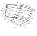
図3は、従来の一般的な貨物船の船尾側縦断面図であり、図面に向かって右側が船首(図示外)、左側が船尾である。また、図4は、従来の一般的貨物船の船舶機関室部分の左舷側透視図である。
Conventional general cargo ships including this type of tanker often have a ship engine room at the rear of the ship because of the demand for securing the maximum cargo space.
Taking a conventional general cargo ship as an example, an outline of the arrangement of the engine room will be described with reference to the drawings.
FIG. 3 is a stern side longitudinal sectional view of a conventional general cargo ship, with the right side being the bow (not shown) and the left side being the stern. FIG. 4 is a port side perspective view of a ship engine room portion of a conventional general cargo ship.
図3において、船舶機関室110は、貨物船100の船舶後部に設けられている。そして、船舶機関室110は、船底外板102の直上にある第1デッキ121を床面とし、乾玄甲板である第5デッキ125を天井面とし、貨物船100の進行方向に直交して立設される船首側の機関室前壁126および船尾側の機関室後壁128と、左舷側外板104および右舷側外板(図示外)と、で囲繞されている。
In FIG. 3, the
図3に示すように、タンクトップ(以下、「第1デッキ」という)121と第5デッキ125の間には、第2デッキ122、第3デッキ123、第4デッキ124が配置されており、主機関112は第1デッキ121上に設置されていて、主機関112の設置部分においては、第2デッキ122、第3デッキ123、第4デッキ124がない、いわゆる吹き抜け空間となっている。そして、たとえば発電機114が第3デッキ123上に設置されているように、その他の機器が船舶機関室110内の各デッキ上に配置されている。
また、燃料タンク116は、左舷側外板104、第5デッキ125および機関室前壁126と、他の三面、すなわち、燃料タンク内壁132、燃料タンク後壁130および底面を鋼製板で形成され、燃料が貯留されている。したがって、図4に示すように、従来の船舶機関室110は、船底部のみが二重底であり、船側である左舷側外板104および右舷側外板(図示外)は単板構造となっている。なお、船側は単板構造ではあるが、桁および肋骨等は設けられており、外洋の水圧には充分耐えられるような構造となっていることは前述した。
The
特開平5−305895号公報に開示された、いわゆるダブルハル構造は、いずれも船体損傷時に貨物タンクからの貨物の漏出を防止することを目的としたものであって、左右の船側外板に沿うサイドバラストタンク部分に関する発明であり、船舶機関室構造そのものをダブルハル構造にするものではない。これは、一方では、船舶の積載貨物量を最大にしなければならないという要請とともに、他方では、推進性能の向上の要請から、船体の前後部を痩せた構造にする必要があり、この痩せた後部のタンクトップ(「第1デッキ」)121に前記主機関112を備え付けなければならなかったことが一因でもあった。さらには、高船速を要求される船舶にあっては、前記主機関112が、さらに大きくなり、船体の前後がより痩せた構造としなければならず、その結果、主機関は、前記第1デッキ121のさらに前方に据え付けざるを得ず、機関室構造をダブルハル構造にするということは考えられなかった。さらに、機関室にダブルハル構造すると、
(1) 船舶機関室の床の有効幅が減少するため、貨物積載スペース118が圧迫されて貨物積載量が減少する、
(2) 船舶機関室をダブルハル構造とすることにより、建造費を含むイニシャルコストが増大する、といった、デメリットがあり、
(3) 上記のようなデメリットに比し、船体損傷時の船舶機関室の燃料タンクからの燃料油の漏洩があったとしても、その量は少量であり、その被害が甚大になるおそれは大きくないといったことが配慮され、機関室をダブルハル構造にしなければならないという技術思想はなかったことが挙げられる。
The so-called double hull structure disclosed in JP-A-5-305895 is intended to prevent the leakage of cargo from the cargo tank when the hull is damaged. The invention relates to the ballast tank portion, and the ship engine room structure itself is not a double hull structure. This is because, on the one hand, it is necessary to maximize the cargo capacity of the ship, and on the other hand, due to the demand for improved propulsion performance, it is necessary to have a structure with the front and rear parts of the hull thinned. This was partly because the
(1) Since the effective width of the floor of the ship engine room decreases, the
(2) The ship engine room has a demerit that the initial cost including the construction cost increases due to the double hull structure.
(3) Compared to the above-mentioned disadvantages, even if there is a leakage of fuel oil from the fuel tank in the ship engine room when the hull is damaged, the amount is small and there is a great risk that the damage will be serious. It is considered that there was no technical idea that the engine room had to have a double hull structure.
そこで、上記のデメリットをも考慮して、本願発明は、船舶機関室への海水の浸水および油の流出する確率を少なくし、安全な船舶と海上汚染防止を目的とした船舶構造を提供しようとするものである。 Therefore, in consideration of the above disadvantages, the present invention seeks to provide a safe ship and a ship structure for the purpose of preventing marine pollution by reducing the probability of seawater flooding and oil spilling into the ship engine room. To do.
上記目的を達成するために、本願請求項1に係る船舶機関室のダブルハル構造は、船舶の進行方向に直交して立設される船首側の機関室前壁および船尾側の機関室後壁と、左舷側外板および右舷側外板(以下、これらを総称するときは「舷側外板」という。)と、で囲繞されて形成される機関室において、床面である第1デッキと乾玄甲板である第nデッキ(nは3以上の自然数)との間に順に第2デッキ、・・・、第(n−1)デッキ(以下、これらを特定しないときは「各デッキ」という。)に、前記舷側外板からそれぞれ所定の距離を隔てた位置(L1)、(L2)、・・・、(Ln−1)上に前記左舷側内壁および右舷側内壁(以下、これらを総称するときは「舷側内壁」という。)が直上の前記各デッキまで垂直方向に水密に立設されて、断面視において前記舷側内壁と前記各デッキとにより階段状に、または、前記(L1)から(L2)へ、(L2)から(L3)へ、・・・、(Ln−1)から(Ln)((Ln)は、前記乾玄甲板である第nデッキの前記舷側外板から所定の距離を隔てた位置(Ln))へ、断面視において前記舷側内壁は前記舷側外板と略同一形状に形成され、前記機関室における船尾側の前記床面は第2デッキとして形成され、前記機関室後壁の位置における前記第1デッキ、前記第2デッキ、・・・、前記第(n−1)デッキの各舷側内壁から舷側外板までの距離をそれぞれα1、α2、・・・、αn-1、前記機関室前壁の位置における前記第1デッキ、前記第2デッキ、・・・、前記第(n−1)デッキの各舷側内壁から舷側外板までの距離をそれぞれβ1、β2、・・・、βn-1としたときに、前記所定の距離は、α1>α2>・・・>αn-1およびβ1>β2>・・・>βn-1であり、かつ、前記機関室前壁側から前記機関室後壁側にかけて徐々に狭まることを特徴とする。
In order to achieve the above object, a double hull structure of a ship engine room according to claim 1 of the present application includes a front wall of the engine room on the bow side and a rear wall of the engine room on the stern side that are set up perpendicular to the traveling direction of the ship. In the engine room surrounded by the port side outer plate and the starboard side outer plate (hereinafter collectively referred to as the “board side outer plate”), the first deck, which is the floor, The second deck,..., The (n-1) th deck (hereinafter referred to as “each deck” when not specified) in order between the deck and the nth deck (n is a natural number of 3 or more). In addition, on the positions (L 1 ), (L 2 ),..., (L n-1 ) respectively spaced apart from the heel-side outer plate, the port-side inner wall and starboard-side inner wall (hereinafter referred to as these) When called generically, it is called “the inner wall on the heel side”). Is set, stepwise by said respective deck and the ship's side inner wall in a cross-sectional view, or from said (L 1) to (L 2), to the (L 2) (L 3) , ···, ( L n-1 ) to (L n ) ((L n ) is a position (L n ) at a predetermined distance from the heel-side outer plate of the n-th deck, which is the dry breech deck), in the cross-sectional view, The heel side inner wall is formed in substantially the same shape as the heel side outer plate, the stern side floor surface in the engine room is formed as a second deck, and the first deck and the second deck at the position of the engine room rear wall. ,..., The distances from the respective inner walls of the (n-1) th deck to the outer side plates are α 1 , α 2 ,..., Α n−1 , at the position of the engine room front wall , respectively. From the first inner side wall of the first deck, the second deck, ..., the (n-1) th deck When the distances to the side outer plates are β 1 , β 2 ,..., Β n-1 , the predetermined distances are α 1 > α 2 >...> Α n-1 and β 1. > Β 2 >...> Β n−1 , and gradually narrows from the engine room front wall side to the engine room rear wall side.
本願請求項1に係る発明によれば、船舶機関室の舷側外板から所定の距離を隔てた位置に舷側内壁が水密に立設されていて、舷側においては、舷側外板と舷側内壁とからなる二重壁となっている。また、船舶機関室の床は船底外板と第1デッキとによる二重床になっていて、いわば、船舶機関室は船舶の外板から所定の距離を保持して浮かんだ状態になっている。そのため、船体損傷時において、船舶機関室への海水の浸水を防止することができるばかりでなく、船舶機関室の付属設備である燃料油タンクは船舶機関室内に設置されることになるから、燃料油の流出する確率は極めて少ないものとなる。 According to the first aspect of the present invention, the shore side inner wall is provided in a watertight manner at a predetermined distance from the shore side outer plate of the ship engine room, and on the shore side, from the shore side outer plate and the shore side inner wall. It has become a double wall. In addition, the floor of the ship engine room is a double floor made up of the ship's bottom skin and the first deck. In other words, the ship engine room is in a state of floating at a predetermined distance from the ship's skin. . Therefore, when the hull is damaged, not only can seawater be prevented from entering the ship engine room, but also the fuel oil tank that is an accessory of the ship engine room is installed in the ship engine room. The probability of oil spilling is very low.
船舶機関室をダブルハル構造とすることによって、外板のダメージによる沈没の危険や油汚染のリスクが大幅に改善される。また、船舶機関室をダブルハル構造とすることにより、船舶機関室内の保温効果の増大により、冬季時における燃料関係のヒーター用関係機器の容量が低減され省エネルギー化をはかることができる。 By making the ship engine room a double hull structure, the risk of sinking due to damage to the outer plate and the risk of oil contamination are greatly improved. In addition, since the ship engine room has a double hull structure, the heat insulation effect in the ship engine room is increased, so that the capacity of the fuel-related heater-related equipment in the winter season can be reduced and energy saving can be achieved.
また、本願請求項2に係る発明によれば、舷側内壁は断面視において階段状となっているため、舷側内壁は各デッキに対して垂直に取り付ければ良いから、加工工作が容易である。また、階段状にすることにより、ダブルハル(二重壁)の強度が向上し、機関室内部に外力の影響を受けにくい。そして、いざ事故があっても、機関室の損傷が少なくて済む等の効果がある。さらに、舷側内壁は垂直面と水平面とにより構成された階段状のデッキが形成されるので、各種ポンプなどの多くの付属機器を整然と据え付けることができ、据え付け場所の有効利用を図ることができる。
According to the invention of
そして、本願請求項3に係る発明によれば、舷側内壁は断面視において舷側外板から所定距離を隔てて舷側外板と略同一形状となっていて、舷側内壁は各デッキに対して垂直方向に対して斜めに取り付けることになり、請求項3に係る発明に比べて加工工作はやや難しくなるものの、船舶機関室内の有効容積は広くなる。
According to the third aspect of the present invention, the heel side inner wall is substantially the same shape as the heel side outer plate at a predetermined distance from the heel side outer plate in a cross-sectional view, and the heel side inner wall is perpendicular to each deck. However, the working volume is somewhat difficult compared with the invention according to
さらに、本願請求項4に係る発明によれば、船舶機関室の船尾側の床面は第2デッキとなっている。この場合、床面である第2デッキ下は、主機関とプロペラとを連結するプロペラシャフトスペースとなっていて、プロペラシャフトのカバーを兼用するため、安全であるとともに、床面である第2デッキ上に機関室に必要な付属機器を載置することができる。
Further, according to the invention of
また、本願請求項5に係る発明によれば、機関室前壁側から機関室後壁側にかけて徐々に狭まっている。この距離は、大きいほど舷側外板損傷時における舷側内壁の安全性は高くなるが、同時に船舶機関室の有効床幅が狭くなり、ひいては貨物積載量の減少に直接的につながるから、バランスのとれた離間距離が必要である。しかし、バランスのとれた離間距離は、船舶の船幅、主機関の大きさにより定まるものであり、一般化することはできず、個別具体的に決定されることになる。なお、船舶は船尾に行くにしたがってその船幅が減少するから、舷側外板と舷側内壁の所定の距離を機関室前壁側から機関室後壁側にかけて徐々に狭くしても、安全性に影響が及ぶことはない。
Moreover, according to the invention which concerns on
以下、本願発明を実施するための最良の形態に係る実施例1および実施例2について、図1、図2および図3に基づいて説明する。なお、図1は、実施例1に係る船舶機関室のダブルハル構造の左舷側透視図であり、図2は、実施例2に係る船舶機関室のダブルハル構造の左舷側透視図である。また、図3は、従来型貨物船の船尾側縦断面図であるが、実施例1および実施例2に係る貨物船の船尾側縦断面図として使用できるので、当該図を用いて説明する。 Hereinafter, Example 1 and Example 2 according to the best mode for carrying out the present invention will be described with reference to FIGS. 1, 2, and 3. FIG. 1 is a port side perspective view of the double hull structure of the marine engine room according to the first embodiment, and FIG. 2 is a port side perspective view of the double hull structure of the marine engine room according to the second embodiment. FIG. 3 is a stern-side longitudinal sectional view of a conventional cargo ship, but can be used as a stern-side longitudinal sectional view of a cargo ship according to Example 1 and Example 2, and will be described with reference to the figure.
図1ないし図3において、符号1は実施例1に係る船舶機関室のダブルハル構造、符号2は実施例2に係る船舶機関室のダブルハル構造、符号11は第1の舷側内壁、符号12は第2の舷側内壁、符号13は第3の舷側内壁、符号14は第4の舷側内壁、符号20は実施例2に係る舷側内壁、符号31は船尾側内壁、符号100は貨物船、符号102は船底外板、符号104は左舷側外板、符号110は船舶機関室、符号112は主機関、符号116は燃料タンク、符号121は第1デッキ、符号122は第2デッキ、符号123は第3デッキ、符号124は第4デッキ、符号125は第5デッキ、符号126は機関室前壁、符号128は機関室後壁、符号130は燃料タンク後壁、符号132は燃料タンク内壁、である。なお、従来型貨物船における同一の要素については、同一の符号を付している。
1 to 3, reference numeral 1 is a double hull structure of a marine engine room according to the first embodiment,
まず、実施例1に係る船舶機関室のダブルハル構造の構成および作用について説明する。船舶機関室110は、従来型貨物船100と同様に、機関室前壁126と、機関室後壁128と、左舷側外板104および右舷側外板(図示外)と、で囲繞されているが、船舶機関室のダブルハル構造1は、主として、船底外板102の船舶内側に立設される舷側内壁から構成されている。そして、舷側内壁は、垂直部材である第1の舷側内壁11、第2の舷側内壁12、第3の舷側内壁13および第4の舷側内壁14と、水平部材である第2デッキ122の側端部、第3デッキ123の側端部および第4デッキ124の側端部と、から構成されていて、断面が階段状となっている。
First, the configuration and operation of the double hull structure of the ship engine room according to the first embodiment will be described. The
すなわち、船舶機関室110の床面である第1デッキ121の左舷側の左舷側外板104から、機関室前壁126の位置における所定の距離(β1)離れた位置と機関室後壁128の位置における所定の距離(α1:図示外)離れた位置とを概ね左舷側外板104に沿って結んだ線(L1)上から第1の舷側内壁11が垂直方向に立設され、この第1の舷側内壁11の上端は第2デッキ122に当接する。さらに、機関室前壁126の位置における所定の距離(β2)離れた位置と機関室後壁128の位置における所定の距離(α2)離れた位置とを概ね左舷側外板104に沿って結んだ線(L2)上から第2の舷側内壁12が垂直方向に立設され、この第2の舷側内壁12の上端は第3デッキ123に当接する。同様にして、第3の舷側内壁13は線(L3)上から立設されその上端は第4デッキ124に当接し、第4の舷側内壁14は線(L4)上から立設されその上端は第5デッキ125に当接することにより、断面が階段状の舷側内壁が形成される。なお、右舷側についても、同様に断面が階段状の舷側内壁が形成されている。
That is, the engine room
この所定の距離(α)および(β)は、それぞれα1>α2>α3>α4、β1>β2>β3>β4という関係になっている。これは、舷側外板が上部から下部にかけて外側に湾曲しながら内側に傾斜していて、第1デッキ121と第1の舷側内壁11とで形成する隅部、・・・、および第4デッキ124と第4の舷側内壁14とで形成する隅部、それぞれが、左舷側外板からの有効離間距離を保持するためである。また、概ねβ1>α1、・・・、β4>α4、となっている。
The predetermined distances (α) and (β) have a relationship of α 1 > α 2 > α 3 > α 4 and β 1 > β 2 > β 3 > β 4, respectively. This is because the heel side outer plate is inclined inward while curving outward from the upper part to the lower part, the corner formed by the
船舶機関室110の床面は、船首側では第1デッキ121であるが、船尾側では第2デッキ122となっている。船首側の第1デッキ121上には、主機関112(図3参照)が設置されているが、船尾側の第2デッキ122下は主機関112から延伸するプロペラシャフト(図3参照)のプロペラシャフトスペースとなっている。そして、船舶機関室110の床面の第1デッキ121と第2デッキ122との間には、船尾側内壁31が立設されている。
なお、従来型貨物船と同様に、船舶機関室110内の機関室前壁126に接して燃料タンク116が形成されている。すなわち、燃料タンク116は、階段状内壁を構成する第2デッキ122の側端部、第3デッキ123の側端部および第4デッキ124の側端部を底板とし、第5デッキ125を蓋板とし、舷側内壁を構成する第1の舷側内壁11、第2の舷側内壁12、第3の舷側内壁13および第4の舷側内壁14と、機関室前壁126と、燃料タンク内壁132と、燃料タンク後壁130の4つの壁面に囲繞されている。
The floor of the
As in the conventional cargo ship, a
上述した船舶機関室のダブルハル構造1の構成により、船舶機関室110は、左舷側外板104から有効距離を保持する階段状の舷側内壁、および右舷側外板(図示外)から有効距離を保持する階段状の舷側内壁が水密に立設されており、かつ、船舶機関室110の床は、船底外板102と第1デッキ121あるいは第2デッキ122とによる二重床になっていて、いわば、船舶機関室110は船舶100の外板から所定の距離を保持して浮かんだ状態になっている。そのため、船体外板の損傷時において、船舶機関室への海水の浸水を防止することができるばかりでなく、船舶機関室110の付属設備である燃料タンク116は船舶機関室内に設置されているから、燃料タンク116内の燃料油の流出する確率は極めて少ないものとなる。さらに、舷側外板と舷側内壁の空間、および船底外板102と船舶機関室110の空間に空気を封入すれば、空気は熱伝導率が低いから船舶機関室110内の保温性能は増大する。
With the above-described configuration of the double hull structure 1 for the ship engine room, the
つぎに、実施例2に係る船舶機関室のダブルハル構造の構成および作用について説明する。船舶機関室のダブルハル構造1と船舶機関室のダブルハル構造2との構成上の相違は、舷側内壁にあるので、相違する舷側内壁について、主に説明する。
Next, the configuration and operation of the double hull structure of the ship engine room according to the second embodiment will be described. Since the structural difference between the double hull structure 1 of the ship engine room and the
船舶機関室のダブルハル構造2は、主として、船底外板102の内側に立設される舷側内壁20から構成されている。舷側内壁20は、第1デッキ121の左舷側の左舷側外板104から機関室前壁126の位置における所定の距離(β1)離れた位置と機関室後壁128の位置における所定の距離(α1:図示外)離れた位置とを概ね左舷側外板104に沿って結んだ線(L1)、第2デッキ122のレベル位置における左舷側外板104から機関室前壁126の位置における所定の距離(β2)離れた位置と機関室後壁128の位置における所定の距離(α2)離れた位置とを概ね左舷側外板104に沿って結んだ線(L2:図2では点線で示す)、・・・、第5デッキ124のレベル位置における左舷側外板104から機関室前壁126の位置における所定の距離(β5)離れた位置と機関室後壁128の位置における所定の距離(α5)離れた位置とを概ね左舷側外板104に沿って結んだ線(L5)、をそれぞれ略直線的に結んだ壁面で構成されていて、断面が左舷側外板104の断面と略同一形状となっている。また、右舷側についても、同様に断面が右舷側外板(図示外)の断面と略同一形状の舷側内壁が形成されている。
なお、所定の距離(α)と(β)、および船舶機関室110の床面については、船舶機関室のダブルハル構造1と同様の構成になっているので、その説明を省略する。
The
Since the predetermined distances (α) and (β) and the floor surface of the
このような船舶機関室のダブルハル構造2の構成により、船舶機関室のダブルハル構造1と同様に、船舶機関室110は、二重壁、二重床により船舶100の外板から所定の距離を保持して浮かんだ状態になっている。したがって、船舶機関室のダブルハル構造2の作用は、船舶機関室のダブルハル構造1と同様の作用を奏するが、船舶機関室のダブルハル構造1より船舶機関室のダブルハル構造2の方が船舶機関室110の有効容積は大きい。
Due to the configuration of the
1 実施例1に係る船舶機関室のダブルハル構造
2 実施例2に係る船舶機関室のダブルハル構造
11 第1の舷側内壁(実施例1に係る舷側内壁)
12 第2の舷側内壁(実施例1に係る舷側内壁)
13 第3の舷側内壁(実施例1に係る舷側内壁)
14 第4の舷側内壁(実施例1に係る舷側内壁)
20 実施例2に係る舷側内壁
100 貨物船
102 船底外板
104 左舷側外板
110 船舶機関室
116 燃料タンク
121 第1デッキ
122 第2デッキ
123 第3デッキ
124 第4デッキ
125 第5デッキ
126 機関室前壁
128 機関室後壁
DESCRIPTION OF SYMBOLS 1 Double hull structure of ship engine room which concerns on Example 1 2 Double hull structure of ship engine room which concerns on Example 2 11 1st ridge side inner wall (the ridge side inner wall which concerns on Example 1)
12 2nd heel side inner wall (the heel side inner wall concerning Example 1)
13 3rd heel side inner wall (the heel side inner wall concerning Example 1)
14 4th heel side inner wall (the heel side inner wall concerning Example 1)
20 Mineral side wall according to Example 2 100
Claims (1)
床面である第1デッキと乾玄甲板である第nデッキ(nは3以上の自然数)との間に順に第2デッキ、・・・、第(n−1)デッキ(以下、これらを特定しないときは「各デッキ」という。)に、前記舷側外板からそれぞれ所定の距離を隔てた位置(L1)、(L2)、・・・、(Ln−1)上に前記左舷側内壁および右舷側内壁(以下、これらを総称するときは「舷側内壁」という。)が直上の前記各デッキまで垂直方向に水密に立設されて、断面視において前記舷側内壁と前記各デッキとにより階段状に、または、前記(L1)から(L2)へ、(L2)から(L3)へ、・・・、(Ln−1)から(Ln)((Ln)は、前記乾玄甲板である第nデッキの前記舷側外板から所定の距離を隔てた位置(Ln))へ、断面視において前記舷側内壁は前記舷側外板と略同一形状に形成され、
前記機関室における船尾側の前記床面は第2デッキとして形成され、
前記機関室後壁の位置における前記第1デッキ、前記第2デッキ、・・・、前記第(n−1)デッキの各舷側内壁から舷側外板までの距離をそれぞれα1、α2、・・・、αn-1、前記機関室前壁の位置における前記第1デッキ、前記第2デッキ、・・・、前記第(n−1)デッキの各舷側内壁から舷側外板までの距離をそれぞれβ1、β2、・・・、βn-1としたときに、前記所定の距離は、α1>α2>・・・>αn-1およびβ1>β2>・・・>βn-1であり、かつ、前記機関室前壁側から前記機関室後壁側にかけて徐々に狭まることを特徴とする船舶機関室のダブルハル構造。 The engine room front wall on the bow side and the stern side engine room rear wall that are set up perpendicular to the traveling direction of the ship, the port side outer plate and the starboard side outer plate. In the engine room formed by being surrounded by
The second deck,..., The (n-1) deck (hereinafter, these are specified) between the first deck that is the floor and the nth deck (n is a natural number greater than or equal to 3) not time as "the deck" in.), a position separated a predetermined distance each from the ship's side outer plate (L 1), (L 2 ), ···, the port side on (L n-1) An inner wall and a starboard side inner wall (hereinafter, collectively referred to as a “board side inner wall”) are vertically and vertically watertight up to the respective decks immediately above, and in a cross-sectional view, the side wall and the decks Stepwise, or from (L 1 ) to (L 2 ), from (L 2 ) to (L 3 ), ..., (L n-1 ) to (L n ) ((L n ) is , A cross-sectional view to a position (L n ) that is a predetermined distance away from the heel side outer plate of the nth deck that is the dry front deck The heel side inner wall is formed in substantially the same shape as the heel side outer plate,
The floor on the stern side in the engine room is formed as a second deck,
The distances from the respective inner side walls of the first deck, the second deck,..., The (n-1) th deck to the outer side outer plate at the position of the rear wall of the engine room are respectively α 1 , α 2 ,. ..., Α n-1 , the distance from each heel side inner wall of the first deck, second deck,..., (N−1) deck to the heel side outer plate at the position of the engine room front wall When β 1 , β 2 ,..., Β n-1 are set, the predetermined distances are α 1 > α 2 >...> Α n-1 and β 1 > β 2 >. A double hull structure for a ship engine room, which is> β n-1 and gradually narrows from the engine room front wall side to the engine room rear wall side.
Priority Applications (1)
| Application Number | Priority Date | Filing Date | Title |
|---|---|---|---|
| JP2005306987A JP4401346B2 (en) | 2005-10-21 | 2005-10-21 | Double hull structure in ship engine room |
Applications Claiming Priority (1)
| Application Number | Priority Date | Filing Date | Title |
|---|---|---|---|
| JP2005306987A JP4401346B2 (en) | 2005-10-21 | 2005-10-21 | Double hull structure in ship engine room |
Publications (2)
| Publication Number | Publication Date |
|---|---|
| JP2007112330A JP2007112330A (en) | 2007-05-10 |
| JP4401346B2 true JP4401346B2 (en) | 2010-01-20 |
Family
ID=38094907
Family Applications (1)
| Application Number | Title | Priority Date | Filing Date |
|---|---|---|---|
| JP2005306987A Expired - Fee Related JP4401346B2 (en) | 2005-10-21 | 2005-10-21 | Double hull structure in ship engine room |
Country Status (1)
| Country | Link |
|---|---|
| JP (1) | JP4401346B2 (en) |
Families Citing this family (4)
| Publication number | Priority date | Publication date | Assignee | Title |
|---|---|---|---|---|
| KR101177905B1 (en) | 2009-04-24 | 2012-08-28 | 삼성중공업 주식회사 | Container ship |
| CN104443259B (en) * | 2014-11-12 | 2017-04-05 | 南通中远川崎船舶工程有限公司 | A kind of method for arranging for reducing roll-on/roll-off vessel for vehicle center of gravity |
| JP6041940B2 (en) * | 2015-08-03 | 2016-12-14 | 三菱重工業株式会社 | Ship |
| CN110588885B (en) * | 2019-09-30 | 2024-03-19 | 中船澄西船舶修造有限公司 | Inclined side plate structure of cabin bottom layer port-starboard cabin channel |
-
2005
- 2005-10-21 JP JP2005306987A patent/JP4401346B2/en not_active Expired - Fee Related
Also Published As
| Publication number | Publication date |
|---|---|
| JP2007112330A (en) | 2007-05-10 |
Similar Documents
| Publication | Publication Date | Title |
|---|---|---|
| KR102169903B1 (en) | Navicular structure | |
| WO2017081996A1 (en) | Ship | |
| CN201825218U (en) | Ship cabin structure | |
| JP4835963B2 (en) | Non-ballast ship | |
| US20100139547A1 (en) | Piping structure for oil tanker | |
| CN105916763A (en) | Icebreaking vessel | |
| US20140238289A1 (en) | Mobile offshore drilling unit | |
| CN105813938A (en) | Ship-shaped structure | |
| JP2008094345A (en) | Method of improving stability of hull when hull is damaged and ship | |
| JP5819755B2 (en) | Ship | |
| JP4401346B2 (en) | Double hull structure in ship engine room | |
| WO2007097610A1 (en) | Semi-submersible vessel, method for operating a semi-submersible vessel and method for manufacturing a semi-submersible vessel | |
| JP5021250B2 (en) | Method for improving stability in case of hull damage and ship | |
| CN210391494U (en) | Semi-submersible transport ship type | |
| US9227702B2 (en) | Ballast system for floating offshore platforms | |
| JP6304554B2 (en) | Ship | |
| JP6368060B1 (en) | Liquid cargo bulk carrier | |
| CN105947123A (en) | Double-body semi-submerged ship with submersible deck | |
| WO2014013584A1 (en) | Ship | |
| JP2019014453A (en) | Vessel-shaped structure | |
| CN201457689U (en) | Shallow-draft vessel body | |
| JP2012153334A (en) | Ship | |
| CN108327847B (en) | Method for transforming buoyancy tank of semi-submersible ship | |
| JP2007050814A (en) | High-speed container ship | |
| JP5969170B2 (en) | Ship |
Legal Events
| Date | Code | Title | Description |
|---|---|---|---|
| A977 | Report on retrieval |
Free format text: JAPANESE INTERMEDIATE CODE: A971007 Effective date: 20080529 |
|
| A131 | Notification of reasons for refusal |
Free format text: JAPANESE INTERMEDIATE CODE: A131 Effective date: 20080610 |
|
| A521 | Written amendment |
Free format text: JAPANESE INTERMEDIATE CODE: A523 Effective date: 20080730 |
|
| A131 | Notification of reasons for refusal |
Free format text: JAPANESE INTERMEDIATE CODE: A131 Effective date: 20090310 |
|
| A521 | Written amendment |
Free format text: JAPANESE INTERMEDIATE CODE: A523 Effective date: 20090325 |
|
| TRDD | Decision of grant or rejection written | ||
| A01 | Written decision to grant a patent or to grant a registration (utility model) |
Free format text: JAPANESE INTERMEDIATE CODE: A01 Effective date: 20091006 |
|
| A01 | Written decision to grant a patent or to grant a registration (utility model) |
Free format text: JAPANESE INTERMEDIATE CODE: A01 |
|
| A61 | First payment of annual fees (during grant procedure) |
Free format text: JAPANESE INTERMEDIATE CODE: A61 Effective date: 20091027 |
|
| R150 | Certificate of patent or registration of utility model |
Free format text: JAPANESE INTERMEDIATE CODE: R150 |
|
| FPAY | Renewal fee payment (event date is renewal date of database) |
Free format text: PAYMENT UNTIL: 20121106 Year of fee payment: 3 |
|
| FPAY | Renewal fee payment (event date is renewal date of database) |
Free format text: PAYMENT UNTIL: 20121106 Year of fee payment: 3 |
|
| FPAY | Renewal fee payment (event date is renewal date of database) |
Free format text: PAYMENT UNTIL: 20151106 Year of fee payment: 6 |
|
| R250 | Receipt of annual fees |
Free format text: JAPANESE INTERMEDIATE CODE: R250 |
|
| LAPS | Cancellation because of no payment of annual fees |