JP4399657B2 - Packaging case - Google Patents
Packaging case Download PDFInfo
- Publication number
- JP4399657B2 JP4399657B2 JP2000171488A JP2000171488A JP4399657B2 JP 4399657 B2 JP4399657 B2 JP 4399657B2 JP 2000171488 A JP2000171488 A JP 2000171488A JP 2000171488 A JP2000171488 A JP 2000171488A JP 4399657 B2 JP4399657 B2 JP 4399657B2
- Authority
- JP
- Japan
- Prior art keywords
- display mount
- piece
- strip
- front wall
- packaging case
- Prior art date
- Legal status (The legal status is an assumption and is not a legal conclusion. Google has not performed a legal analysis and makes no representation as to the accuracy of the status listed.)
- Expired - Fee Related
Links
Images


Landscapes
- Packages (AREA)
Description
【0001】
【発明の属する技術分野】
本発明は、種々の商品を被包装物として包装するための包装ケースの改良に関する。
【0002】
【従来の技術】
一般に、この種の包装ケースとしては、紙製の台紙部と、プラスチックシートをシート成形することにより、後方側に開口する収容凹部が形成された収容部とから構成された、いわゆるブリスターパックが多用されている。
そして、台紙部にはその両面に商品説明等の表示が印刷により施され、プラスチックシートは透明なものが使用されて前面側から商品が透視可能となっており、店頭での陳列に適している。
【0003】
【発明が解決しようとする課題】
しかしながら、シート成形のための成形型が必要で、また、製造工程においても、シート成形工程が必要で製造設備が大型化する。しかも、紙とプラスチックシートという二種類のシート材が必要にもなる。
従って、大量生産には好適であるものの、多品種小ロット生産にはコスト等の観点から必ずしも適したものとは言えない。
また、紙とプラスチックを分別廃棄しなければならないという問題もある。
【0004】
そこで本発明は、上記従来の問題点に鑑みてなされ、ブリスターパックの代替品として、製造コストが少なく製造容易であって小ロット生産に適した包装ケースを提供することを課題とする。
【0005】
【課題を解決するための手段】
本発明は、上記課題を解決すべくなされたものであり、本発明に係る包装ケースは、商品説明等の表示を施すための表示用台紙部と、該表示用台紙部の前面側において被包装物の略全体を表示用台紙部と共に包装すべく、後方側に開口した収容部とを備え、表示用台紙部は収容部の外形よりも大きな面積を有しており、表示用台紙部と収容部は、一枚の展開状のプラスチックシートから形成されており、収容部は、収容部の前面を構成する前壁部と、一方の側縁部において前壁部と連設され且つ、前壁部の外形に略沿って曲げられて収容部の周面を構成する帯状片部とを備え、表示用台紙部と前壁部と帯状片部とで被包装物の略全体が包囲されていることを特徴とする。
【0007】
更に、表示用台紙部、表示用台紙部と前壁部の下縁部同士を連結する連結片部、前壁部、帯状片部の順に連設された展開状のプラスチックシートが使用され、連結片部が載置面となって包装ケースは自立可能に構成されており、帯状片部の他方の側縁部には固定片部が延設され、該固定片部で帯状片部は表示用台紙部と固定され、帯状片部の両端部同士が連結片部の内側で繋ぎ合わせられていることが好ましい。
【0008】
【発明の実施の形態】
以下、本発明の包装ケースの一実施形態について図1乃至図5を参酌しつつ、説明する。
【0009】
本実施形態における包装ケースは、商品説明等の表示を施すための表示用台紙部Aと、該表示用台紙部Aの前面側において、被包装物としての円柱状物品Cの略全体を表示用台紙部Aと共に包装すべく、後方側に開口した収容部Bとを備える。
【0010】
収容部Bは、円柱状物品Cの軸線が前後方向となるように該物品Cを収容すべく物品Cの外形に沿った形状とされており、収容部Bの前面を構成する略円形状の前壁部1と、該前壁部1と表示用台紙部Aとの間に位置して、収容部Bの略円筒状の周面を構成する帯状片部4とから構成される。そして、前壁部1、帯状片部4及び表示用台紙部Aによって物品Cの略全体を包囲する構成となっている。
【0011】
また、表示用台紙部Aは、略矩形に形成され、収容部Bの外形よりも大きな面積を有している。即ち、表示用台紙部Aは、収容部Bの外形よりも外側にはみ出したはみ出し部A1を有しており、上方側には吊下用孔2が形成されて吊り下げ可能になっている。
【0012】
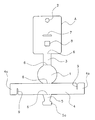
かかる包装ケースは、図5に示すような一枚の展開状のプラスチックシートから形成されている。即ち、かかる展開状のプラスチックシートにおいて、その一方側から順に表示用台紙部A、連結片部3、前壁部1、帯状片部4、固定片部5が縦方向に連設され、これらの部位は折曲罫線が刻設された折り目6を介して区画されている。
【0013】
表示用台紙部Aには、吊下用孔2、固定片部5の差し込み用スリット7、固定片部5の係止用孔8が縦方向に並んで形成されている。また、連結片部3は、表示用台紙部Aと前壁部1の下縁部同士を連結し、表示用台紙部Aや前壁部1よりも幅狭である。更に、帯状片部4は、横方向に沿って略一定幅の細長い帯状であり、その一方の側縁部略中央において前壁部1と折り目6を介して連設され、前壁部1の外形一周分以上の長さを有している。尚、この帯状片部4が前壁部1の外形に沿って筒状に曲げられ、両端部4a同士が繋ぎ合わせられて収容部Bの略円筒状の周面を構成する。その繋ぎ合わせのために、帯状片部4は、その一方の側縁部における一端部側にスリット状の切欠部9が幅方向に沿って形成され、他方の側縁部における他端部側にも左右対称の位置関係を有して同形状のスリット状の切欠部9が形成されている。そして、左右のスリット状の切欠部9同士を係合させることで筒状となる。(図2、図3参照)
【0014】
一方、固定片部5は、帯状片部4の他方の側縁部略中央位置に折り目6を介して延設され、その先端部には左右両側に張り出した係止用張り出し部5aが形成されて、全体として略逆T字状を呈している。
【0015】
ここで、プラスチックシートとしては、被包装物を透視可能な透明、半透明のものを使用でき、例えば、厚さ0.1mm乃至0.5mm程度のポリエステル、ポリプロピレン、ポリ塩化ビニル製のシートを用いることができる。そして、表示用台紙部Aの両面の所定箇所に印刷が施され、所定形状に打ち抜かれる。
【0016】
以上のような展開状のプラスチックシートを使用した包装ケースの組立について説明する。
【0017】
まず、スリット状の切欠部9同士を係合させて帯状片部4を略円筒状にして収容部Bの周面を形成する。このように両端部4a同士を相互に係合させることによって容易に繋ぎ合わせることができる。
【0018】
そして、前壁部1を折り目6で折り曲げて後方側に開口した収容部Bを形成してその収容部Bに被包装物を入れ、更に、前壁部1と連結片部3との間、及び、連結片部3と表示用台紙部Aとの間を各々折り目6で折り曲げる。これにより、表示用台紙部Aと前壁部1とが略平行となり、且つ、表示用台紙部Aで収容部Bの開口が略閉口されて、表示用台紙部Aと前壁部1と帯状片部4とで円柱状物品Cの略全体が包囲される。
【0019】
その後、固定片部5を差し込み用スリット7に差し込み、表示用台紙部Aの後面から引き出した固定片部5の先端部を図4のように係止用孔8に前方側へと押入する。固定片部5の先端部は、係止用張り出し部5aが形成されていて係止用孔8の開口面積に比して大きいため、この係止用張り出し部5aが係止用孔8の開口縁部で係止され、その結果、固定片部5で帯状片部4を表示用台紙部Aに固定することができる。
【0020】
以上のようにして一枚の展開状のプラスチックシートから図1に示すような包装ケースを簡単に組み立てることができる。また、シート各部位の係合により固定する構成なるため、固定に接着剤を使用する必要もない。
【0021】
更に、前壁部1と連設された帯状片部4で周面を構成したことにより、被包装物の略全体を容易に包装することができ、包装ケース全体が透視若しくは半透明のプラスチックシートから形成されているので、基本的に全方向から被包装物を透視可能である。
【0022】
また、被包装物を包装ケースで包装した包装体は、吊下用孔2を用いて吊り下げ陳列される以外にも、連結片部3が載置面となって自立状態で陳列等される。このように包装ケースを自立状態とする場合、図2及び図3のように、繋ぎ合わせられた帯状片部4の両端部4aが連結片部3の内側位置において繋ぎ合わせられているので、自立の際の邪魔にならない。しかも、帯状片部4の両端部4aが各々連結片部3から左右方向にはみ出した状態となるので、このはみ出した帯状片部4の両端部4aによって、包装ケースの接地面積が連結片部3のみの場合に比して増加し、自立状態がより一層安定する。また、繋ぎ合わせた部分が下側にあるので見えにくく外観上も良好である。
【0023】
尚、円柱状物品Cの形状に合わせて帯状片部4を円筒状とした場合について説明したが、図6のようなプラスチックシートを使用して正面視略矩形の収容部Bを構成するようにしてもよい。その場合、帯状片部4を折り曲げて角筒状の周面を構成するので、同図の如く、帯状片部4の所定箇所に幅方向に沿った折り目6を形成することが好ましい。
【0024】
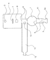
また、表示用台紙部Aと前壁部1の下端部同士を連結する連結片部3に代えて、図7や図8のように、表示用台紙部Aと前壁部1との間の位置に帯状片部10を設けることも可能である。即ち、帯状片部10の一方の側縁部において前壁部1が連設され、他方の側縁部において表示用台紙部Aが連設される構成である。この構成では、図7のように、帯状片部10の略中央位置に表示用台紙部Aと前壁部1とが位置する構成とする他、図8のように、帯状片部10の一端部に表示用台紙部Aと前壁部1とを位置させることもできる。更に、図7や図8の構成では、前壁部1の上縁部と表示用台紙部Aとを連結するための連結片部11が、前壁部1の上縁部に延設され、該連結片部11から更に固定片部5が延設されている。そして、図7の構成では、帯状片部10が連結片部11の内側(下方側)位置で両端部10aがスリット状の両切欠部9で繋ぎ合わせられるが、連結片部11の外側で繋ぎ合わせてもよい。同様に図5や図6の場合でも連結片部3の外側で帯状片部4を繋ぎ合わせることもできる。
【0025】
一方、図8の構成では、長手方向先端部(一端部)に係止用張り出し部12が形成され、該先端部が一周して基端部(他端部)に設けられた係止用孔13に差し込まれて係止されて筒状となる構成である。
【0026】
このように、帯状片部の両端部同士を繋ぎ合わせる構成も種々の構成を採用でき、無論、接着等によって繋ぎ合わせてもよい。また、帯状片部の両端部同士を繋ぎ合わせる以外にも、その端部を連結片部に直接繋ぐこともできる。
更に、表示用台紙部Aと前壁部1との間、前壁部1と固定片部5との間に、収容部Bの周面の略半周分の長さの帯状片部を各々設ける構成とすることもできる。
【0027】
何れにしても、一方の側縁部において前壁部1と連結された帯状片部を設け、該帯状片部を前壁部1の外形に略沿って曲げることによって収容部Bの周面を構成することにより、被包装物の前後両面のみならず略全体を容易に包囲することができるのである。
【0028】
尚、固定片部5の表示用台紙部Aとの固定方法についても適宜設計変更可能であり、例えば、係止用張り出し部5aに代えて、図9のように、固定片部5の先端部に切り込み5bを形成し、切り込み5bによって区画される舌片状の差込部5cを表示用台紙部Aの係止用孔8の開口縁部にひっかけて固定することもできる。無論、固定片部5を直接表示用台紙部Aの後面や前面に貼着してもよい。また、固定片部5を例えば帯状片部の他方の側縁部に複数箇所設けることもできる。
【0029】
【発明の効果】
以上のように、一枚の展開状のプラスチックシートから被包装物の略全体を覆うことができる構成としたので、ブリスターパックのようなシート成形が不要となり、製造が容易且つ安価となって小ロット生産に好適である。
【図面の簡単な説明】
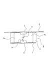
【図1】本発明の一実施形態における包装ケースを示す斜視図。
【図2】同包装ケースの要部を示す一部破断線を含む背面図。
【図3】同包装ケースの一部破断線を含む底面図。
【図4】図2のP−P断面図。
【図5】同包装ケースの展開図。
【図6】他実施形態における包装ケースの展開図。
【図7】他実施形態における包装ケースの展開図。
【図8】他実施形態における包装ケースの展開図。
【図9】他実施形態における包装ケースの要部を示す背面図。
【符号の説明】
A…表示用台紙部、B…収容部、C…円柱状物品(被包装物)、1…前壁部、2…吊下用孔、3,11…連結片部、4,10…帯状片部、4a…端部、5…固定片部、5a,12…係止用張り出し部、5b…切り込み、5c…差込部、6…折り目、7…差し込み用スリット、8,13…係止用孔、9…切欠部[0001]
BACKGROUND OF THE INVENTION
The present invention relates to an improvement of a packaging case for packaging various products as an article to be packaged.
[0002]
[Prior art]
In general, as this type of packaging case, a so-called blister pack composed of a paper mount and an accommodation portion formed with an accommodation recess opened to the rear side by forming a plastic sheet is often used. Has been.
In addition, on the both sides of the mount, the product description is displayed by printing, and a transparent plastic sheet is used so that the product can be seen through from the front side, which is suitable for display in stores. .
[0003]
[Problems to be solved by the invention]
However, a mold for forming the sheet is required, and also in the manufacturing process, the sheet forming process is required, and the manufacturing equipment is enlarged. In addition, two types of sheet materials, paper and plastic sheet, are required.
Therefore, although it is suitable for mass production, it is not necessarily suitable for multi-product small-lot production from the viewpoint of cost.
Another problem is that paper and plastic must be disposed of separately.
[0004]
Therefore, the present invention has been made in view of the above-described conventional problems, and an object of the present invention is to provide a packaging case that is low in manufacturing cost and easy to manufacture and suitable for small lot production as an alternative to a blister pack.
[0005]
[Means for Solving the Problems]
The present invention has been made to solve the above-mentioned problems, and a packaging case according to the present invention includes a display mount for displaying a product description and the like, and a package on the front side of the display mount. In order to wrap almost the entire object together with the display mount part, it is provided with a storage part opened on the rear side, and the display mount part has an area larger than the outer shape of the storage part, and is accommodated with the display mount part. The portion is formed from a single unfolded plastic sheet, and the storage portion is connected to the front wall portion that constitutes the front surface of the storage portion, and the front wall portion at one side edge portion, and the front wall A strip-shaped piece that is bent substantially along the outer shape of the container and constitutes the peripheral surface of the housing portion, and the display mount, the front wall, and the strip-shaped piece surround the substantially entire package . It is characterized by that.
[0007]
In addition, a display-type mount part, a connecting piece part for connecting the display mount part and the lower edge part of the front wall part, a front wall part, and a strip-like piece part connected in this order are used and connected. The packaging case is configured to be able to stand on its own as a mounting surface, and a fixed piece is extended on the other side edge of the strip-shaped piece, and the strip-shaped piece is used for display in the fixed piece. It is preferable that both ends of the belt-like piece portions are fixed to each other on the inner side of the connecting piece portion.
[0008]
DETAILED DESCRIPTION OF THE INVENTION
Hereinafter, an embodiment of the packaging case of the present invention will be described with reference to FIGS. 1 to 5.
[0009]
The packaging case in the present embodiment is for displaying a display mount portion A for displaying product descriptions and the like, and on the front side of the display mount portion A, substantially the entire cylindrical article C as a packaged item. In order to be packaged together with the mount part A, a housing part B opened to the rear side is provided.
[0010]
The accommodating part B has a shape along the outer shape of the article C so as to accommodate the article C so that the axis of the cylindrical article C is in the front-rear direction, and has a substantially circular shape constituting the front surface of the accommodating part B. It is comprised from the
[0011]
Further, the display mount portion A is formed in a substantially rectangular shape and has a larger area than the outer shape of the storage portion B. That is, the display mount portion A has a protruding portion A1 that protrudes outward from the outer shape of the accommodating portion B, and a
[0012]
Such a packaging case is formed from one unfolded plastic sheet as shown in FIG. That is, in such an unfolded plastic sheet, the display mount part A, the
[0013]
In the display mount portion A, a
[0014]
On the other hand, the
[0015]
Here, as the plastic sheet, a transparent or translucent material that can be seen through the package can be used. For example, a sheet made of polyester, polypropylene, or polyvinyl chloride having a thickness of about 0.1 mm to 0.5 mm is used. be able to. Then, printing is performed on predetermined positions on both sides of the display mount A and punched into a predetermined shape.
[0016]
The assembly of the packaging case using the unfolded plastic sheet as described above will be described.
[0017]
First, the slit-
[0018]
And the
[0019]
Thereafter, the fixed
[0020]
As described above, a packaging case as shown in FIG. 1 can be easily assembled from a single developed plastic sheet. Moreover, since it becomes the structure fixed by engagement of each site | part of a sheet | seat, it is not necessary to use an adhesive agent for fixation.
[0021]
Furthermore, since the peripheral surface is constituted by the strip-shaped
[0022]
In addition, the package body in which the packaged object is packaged in the packaging case is displayed in a self-supported state in which the connecting
[0023]
In addition, although the case where the strip | belt-shaped
[0024]
Further, instead of the connecting
[0025]
On the other hand, in the configuration of FIG. 8, a locking
[0026]
As described above, various configurations can be adopted for connecting both end portions of the strip-shaped piece portions, and of course, they may be connected by bonding or the like. In addition to connecting both ends of the strip-shaped piece, the ends can be directly connected to the connecting piece.
Furthermore, a strip-shaped piece portion having a length corresponding to a substantially half circumference of the peripheral surface of the accommodating portion B is provided between the display mount portion A and the
[0027]
In any case, a belt-like piece connected to the
[0028]
Note that the method of fixing the fixing
[0029]
【The invention's effect】
As described above, since it is configured to cover almost the entire package from a single unfolded plastic sheet, it is not necessary to form a sheet like a blister pack, and it is easy and inexpensive to manufacture. Suitable for lot production.
[Brief description of the drawings]
FIG. 1 is a perspective view showing a packaging case according to an embodiment of the present invention.
FIG. 2 is a rear view including a partially broken line showing a main part of the packaging case.
FIG. 3 is a bottom view including a partially broken line of the packaging case.
4 is a cross-sectional view taken along the line PP in FIG. 2;
FIG. 5 is a development view of the packaging case.
FIG. 6 is a development view of a packaging case in another embodiment.
FIG. 7 is a development view of a packaging case in another embodiment.
FIG. 8 is a development view of a packaging case in another embodiment.
FIG. 9 is a rear view showing a main part of a packaging case according to another embodiment.
[Explanation of symbols]
A ... Mount for display, B ... Storage part, C ... Cylindrical article (packaged object), 1 ... Front wall part, 2 ... Suspension hole, 3, 11 ... Connection piece part, 4, 10 ... Strip piece Part, 4a ... end part, 5 ... fixed piece part, 5a, 12 ... overhang part for locking, 5b ... notch, 5c ... insertion part, 6 ... fold, 7 ... slit for insertion, 8, 13 ... for locking Hole, 9 ... notch
Claims (2)
Priority Applications (1)
| Application Number | Priority Date | Filing Date | Title |
|---|---|---|---|
| JP2000171488A JP4399657B2 (en) | 2000-06-08 | 2000-06-08 | Packaging case |
Applications Claiming Priority (1)
| Application Number | Priority Date | Filing Date | Title |
|---|---|---|---|
| JP2000171488A JP4399657B2 (en) | 2000-06-08 | 2000-06-08 | Packaging case |
Publications (2)
| Publication Number | Publication Date |
|---|---|
| JP2001348058A JP2001348058A (en) | 2001-12-18 |
| JP4399657B2 true JP4399657B2 (en) | 2010-01-20 |
Family
ID=18674030
Family Applications (1)
| Application Number | Title | Priority Date | Filing Date |
|---|---|---|---|
| JP2000171488A Expired - Fee Related JP4399657B2 (en) | 2000-06-08 | 2000-06-08 | Packaging case |
Country Status (1)
| Country | Link |
|---|---|
| JP (1) | JP4399657B2 (en) |
Families Citing this family (1)
| Publication number | Priority date | Publication date | Assignee | Title |
|---|---|---|---|---|
| JP5008935B2 (en) * | 2006-09-28 | 2012-08-22 | 株式会社フジシールインターナショナル | Cylindrical article holding case |
-
2000
- 2000-06-08 JP JP2000171488A patent/JP4399657B2/en not_active Expired - Fee Related
Also Published As
| Publication number | Publication date |
|---|---|
| JP2001348058A (en) | 2001-12-18 |
Similar Documents
| Publication | Publication Date | Title |
|---|---|---|
| CA2661761C (en) | Blister package assembly for confectionary products | |
| US20060010560A1 (en) | Retail display strap for securing a tie to a shirt | |
| JP5016436B2 (en) | Package | |
| JP4399657B2 (en) | Packaging case | |
| US11577896B2 (en) | Packaging device | |
| JP6794676B2 (en) | Self-supporting packaging | |
| JP2000072133A (en) | Box with pop-up display board | |
| JP3049929U (en) | Packaging box for detachable numeric keyboard | |
| JP2012086903A (en) | Cylindrical article holding case | |
| JP2005219787A (en) | Product fixing mount paper sheet | |
| JP6856982B2 (en) | Packaging box | |
| JPH10316164A (en) | Shrink with mount | |
| JP2006206147A (en) | Package of article | |
| JP2576492Y2 (en) | Tubular container storage box | |
| JPH1129139A (en) | Package for writing material | |
| KR200241831Y1 (en) | Tobacco open type case model for display | |
| JPS6223696Y2 (en) | ||
| CN117446312A (en) | Product display packaging | |
| JP3417429B2 (en) | Packaging containers | |
| JPH023349Y2 (en) | ||
| JP3201328U (en) | Packaging box | |
| JP3124449U (en) | Blister package | |
| JP5008935B2 (en) | Cylindrical article holding case | |
| JP4321940B2 (en) | Packaging display box | |
| JP3170263U (en) | Integrated mount for shirts |
Legal Events
| Date | Code | Title | Description |
|---|---|---|---|
| RD04 | Notification of resignation of power of attorney |
Free format text: JAPANESE INTERMEDIATE CODE: A7424 Effective date: 20040706 |
|
| A711 | Notification of change in applicant |
Free format text: JAPANESE INTERMEDIATE CODE: A711 Effective date: 20060106 |
|
| A621 | Written request for application examination |
Free format text: JAPANESE INTERMEDIATE CODE: A621 Effective date: 20070516 |
|
| RD02 | Notification of acceptance of power of attorney |
Free format text: JAPANESE INTERMEDIATE CODE: A7422 Effective date: 20070516 |
|
| A977 | Report on retrieval |
Free format text: JAPANESE INTERMEDIATE CODE: A971007 Effective date: 20090608 |
|
| A131 | Notification of reasons for refusal |
Free format text: JAPANESE INTERMEDIATE CODE: A131 Effective date: 20090616 |
|
| A521 | Written amendment |
Free format text: JAPANESE INTERMEDIATE CODE: A523 Effective date: 20090723 |
|
| TRDD | Decision of grant or rejection written | ||
| A01 | Written decision to grant a patent or to grant a registration (utility model) |
Free format text: JAPANESE INTERMEDIATE CODE: A01 Effective date: 20091002 |
|
| A01 | Written decision to grant a patent or to grant a registration (utility model) |
Free format text: JAPANESE INTERMEDIATE CODE: A01 |
|
| A61 | First payment of annual fees (during grant procedure) |
Free format text: JAPANESE INTERMEDIATE CODE: A61 Effective date: 20091013 |
|
| R150 | Certificate of patent or registration of utility model |
Free format text: JAPANESE INTERMEDIATE CODE: R150 |
|
| FPAY | Renewal fee payment (event date is renewal date of database) |
Free format text: PAYMENT UNTIL: 20121106 Year of fee payment: 3 |
|
| FPAY | Renewal fee payment (event date is renewal date of database) |
Free format text: PAYMENT UNTIL: 20121106 Year of fee payment: 3 |
|
| S531 | Written request for registration of change of domicile |
Free format text: JAPANESE INTERMEDIATE CODE: R313531 |
|
| FPAY | Renewal fee payment (event date is renewal date of database) |
Free format text: PAYMENT UNTIL: 20121106 Year of fee payment: 3 |
|
| R350 | Written notification of registration of transfer |
Free format text: JAPANESE INTERMEDIATE CODE: R350 |
|
| FPAY | Renewal fee payment (event date is renewal date of database) |
Free format text: PAYMENT UNTIL: 20121106 Year of fee payment: 3 |
|
| FPAY | Renewal fee payment (event date is renewal date of database) |
Free format text: PAYMENT UNTIL: 20131106 Year of fee payment: 4 |
|
| R250 | Receipt of annual fees |
Free format text: JAPANESE INTERMEDIATE CODE: R250 |
|
| R250 | Receipt of annual fees |
Free format text: JAPANESE INTERMEDIATE CODE: R250 |
|
| R250 | Receipt of annual fees |
Free format text: JAPANESE INTERMEDIATE CODE: R250 |
|
| R250 | Receipt of annual fees |
Free format text: JAPANESE INTERMEDIATE CODE: R250 |
|
| LAPS | Cancellation because of no payment of annual fees |