JP4395679B2 - Magnetic tape recording apparatus and method, magnetic tape reproducing apparatus and method, magnetic tape, and recording medium - Google Patents
Magnetic tape recording apparatus and method, magnetic tape reproducing apparatus and method, magnetic tape, and recording medium Download PDFInfo
- Publication number
- JP4395679B2 JP4395679B2 JP2000104838A JP2000104838A JP4395679B2 JP 4395679 B2 JP4395679 B2 JP 4395679B2 JP 2000104838 A JP2000104838 A JP 2000104838A JP 2000104838 A JP2000104838 A JP 2000104838A JP 4395679 B2 JP4395679 B2 JP 4395679B2
- Authority
- JP
- Japan
- Prior art keywords
- data
- group
- magnetic tape
- unit
- auxiliary
- Prior art date
- Legal status (The legal status is an assumption and is not a legal conclusion. Google has not performed a legal analysis and makes no representation as to the accuracy of the status listed.)
- Expired - Fee Related
Links
Images


Classifications
-
- G—PHYSICS
- G11—INFORMATION STORAGE
- G11B—INFORMATION STORAGE BASED ON RELATIVE MOVEMENT BETWEEN RECORD CARRIER AND TRANSDUCER
- G11B20/00—Signal processing not specific to the method of recording or reproducing; Circuits therefor
- G11B20/10—Digital recording or reproducing
- G11B20/12—Formatting, e.g. arrangement of data block or words on the record carriers
-
- G—PHYSICS
- G11—INFORMATION STORAGE
- G11B—INFORMATION STORAGE BASED ON RELATIVE MOVEMENT BETWEEN RECORD CARRIER AND TRANSDUCER
- G11B5/00—Recording by magnetisation or demagnetisation of a record carrier; Reproducing by magnetic means; Record carriers therefor
- G11B5/02—Recording, reproducing, or erasing methods; Read, write or erase circuits therefor
- G11B5/09—Digital recording
-
- G—PHYSICS
- G11—INFORMATION STORAGE
- G11B—INFORMATION STORAGE BASED ON RELATIVE MOVEMENT BETWEEN RECORD CARRIER AND TRANSDUCER
- G11B20/00—Signal processing not specific to the method of recording or reproducing; Circuits therefor
- G11B20/10—Digital recording or reproducing
- G11B20/12—Formatting, e.g. arrangement of data block or words on the record carriers
- G11B20/1201—Formatting, e.g. arrangement of data block or words on the record carriers on tapes
- G11B20/1207—Formatting, e.g. arrangement of data block or words on the record carriers on tapes with transverse tracks only
- G11B20/1208—Formatting, e.g. arrangement of data block or words on the record carriers on tapes with transverse tracks only for continuous data, e.g. digitised analog information signals, pulse code modulated [PCM] data
-
- G—PHYSICS
- G11—INFORMATION STORAGE
- G11B—INFORMATION STORAGE BASED ON RELATIVE MOVEMENT BETWEEN RECORD CARRIER AND TRANSDUCER
- G11B5/00—Recording by magnetisation or demagnetisation of a record carrier; Reproducing by magnetic means; Record carriers therefor
- G11B5/008—Recording on, or reproducing or erasing from, magnetic tapes, sheets, e.g. cards, or wires
- G11B5/00813—Recording on, or reproducing or erasing from, magnetic tapes, sheets, e.g. cards, or wires magnetic tapes
- G11B5/00847—Recording on, or reproducing or erasing from, magnetic tapes, sheets, e.g. cards, or wires magnetic tapes on transverse tracks
- G11B5/0086—Recording on, or reproducing or erasing from, magnetic tapes, sheets, e.g. cards, or wires magnetic tapes on transverse tracks using cyclically driven heads providing segmented tracks
-
- G—PHYSICS
- G11—INFORMATION STORAGE
- G11B—INFORMATION STORAGE BASED ON RELATIVE MOVEMENT BETWEEN RECORD CARRIER AND TRANSDUCER
- G11B2220/00—Record carriers by type
- G11B2220/90—Tape-like record carriers
-
- G—PHYSICS
- G11—INFORMATION STORAGE
- G11B—INFORMATION STORAGE BASED ON RELATIVE MOVEMENT BETWEEN RECORD CARRIER AND TRANSDUCER
- G11B2220/00—Record carriers by type
- G11B2220/90—Tape-like record carriers
- G11B2220/91—Helical scan format, wherein tracks are slightly tilted with respect to tape direction, e.g. VHS, DAT, DVC, AIT or exabyte
Landscapes
- Engineering & Computer Science (AREA)
- Signal Processing (AREA)
- Signal Processing For Digital Recording And Reproducing (AREA)
- Television Signal Processing For Recording (AREA)
Description
【0001】
【発明の属する技術分野】
本発明は、磁気テープ記録装置および方法、磁気テープ再生装置および方法、磁気テープ、並びに記録媒体に関し、特に、高品位の映像データを磁気テープに記録または再生できるようにした、磁気テープ記録装置および方法、磁気テープ再生装置および方法、磁気テープ、並びに記録媒体に関する。
【0002】
【従来の技術】
最近、圧縮技術が進み、映像データなども、例えば、DV(Digital Video)方式により圧縮され、磁気テープに記録されるようになってきた。そのためのフォーマットが、民生用デジタルビデオテープレコーダのDVフォーマットとして規定されている。
【0003】
図1は、従来のDVフォーマットの1トラックの構成を表している。なお、DVフォーマットにおいては、映像データは、24−25変換されて記録されるが、図1に示す数字のビット数は、24−25変換された後の数値を表している。
【0004】
磁気テープの174度の巻き付け角に対応する範囲が、実質的な1トラックの範囲とされる。この1トラックの範囲の外には、1250ビットの長さのオーバーライトマージンが形成されている。このオーバーライトマージンは、データの消し残りをなくすためのものである。
【0005】
1トラックの範囲の長さは、60×1000/1001Hzの周波数に同期して回転ヘッドが回転される場合、134975ビットとされ、60Hzの周波数に同期して回転ヘッドが回転される場合、134850ビットとされる。
【0006】
この1トラックには、磁気ヘッドのトレース方向(図1において、左から右方向)に、ITIセクタ、オーディオセクタ、ビデオセクタ、サブコードセクタが順次配置され、ITIセクタとオーディオセクタの間にはギャップG1が、オーディオセクタとビデオセクタの間にはギャップG2が、そしてビデオセクタとサブコードセクタの間にはギャップG3が、それぞれ形成される。
【0007】
ITI(Insert and Track Information)セクタは、3600ビットの長さとされ、その先頭にはクロックを生成するための1400ビットのプリアンブルが配置され、その次にはSSA(Start Sync Area)とTIA(Track Information Area)が1920ビット分の長さ設けられている。SSAには、TIAの位置を検出するために必要なビット列(シンク番号)が配置されている。TIAには民生用のDVフォーマットであることを示す情報、SPモードまたはLPモードであることを表す情報、1フレームのパイロット信号のパターンを表す情報などが記録されている。TIAの次には、280ビットのポストアンブルが配置されている。
【0008】
ギャップG1の長さは、625ビット分とされている。
【0009】
オーディオセクタは11550ビットの長さとされ、その先頭の400ビットと最後の500ビットは、それぞれプリアンブルまたはポストアンブルとされ、その間の10650ビットがデータ(オーディオデータ)とされる。
【0010】
ギャップG2は、700ビットの長さとされる。
【0011】
ビデオセクタは113225ビットとされ、その先頭の400ビットと最後の925ビットが、それぞれプリアンブルまたはポストアンブルとされ、その間の111900ビットがデータ(ビデオデータ)とされる。
【0012】
ギャップG3の長さは、1550ビットとされる。
【0013】
サブコードセクタは、回転ヘッドが60×1000/1001Hzの周波数で回転されるとき、3725ビットとされ、60Hz周波数で回転されるとき、3600ビットとされる。そのうちの先頭の1200ビットは、プリアンブルとされ、最後の1325ビット(回転ヘッドが60×1000/1001Hzの周波数で回転される場合)、または1200ビット(回転ヘッドが60Hzの周波数で回転される場合)とされ、その間の1200ビットがデータ(サブコード)とされる。
【0014】
【発明が解決しようとする課題】
DVフォーマットにおいては、このように、ITIセクタ、オーディオセクタ、ビデオセクタ、およびサブコードセクタの間に、ギャップG1乃至G3が形成されているばかりでなく、各セクタ毎にプリアンブルとポストアンブルが設けられており、いわゆるオーバーヘッドが多く、実質的なデータの記録レートを充分に得ることができない課題があった。
【0015】
その結果、例えば、高品位の映像データ(以下、HD(High Definition)映像データと称する)を記録するには、25Mbps程度のビットレートが必要であるが、この記録フォーマットでは、MPEG(Moving Picture Expert Group)方式のMP@HLに対するビデオレートは、サーチ画像用データを除くと、せいぜい24Mbps程度しか確保できず、結果的に、標準の品位の映像データ(以下、SD(Standard Definition)映像データと称する)は記録できても、HD映像データをMP@HL、MP@H−14方式などで圧縮して記録することができない課題があった。
【0016】
本発明はこのような状況に鑑みてなされたものであり、HDデータを記録または再生できるようにするものである。
【0017】
【課題を解決するための手段】
本発明の磁気テープ記録装置は、映像データ、音声データ及びサーチデータのうち少なくとも一つを取得する第1の取得手段と、第1の取得手段により取得されたデータに関連する可変長の補助データを取得する第2の取得手段と、第1の取得手段及び第2の取得手段により取得されたデータのうち少なくとも一つを第1のグループのデータとして選択する選択手段と、第1のグループのデータに関連するサブコードを含む第2のグループのデータを取得する第3の取得手段と、第1のグループのデータと第2のグループのデータを、磁気テープのトラック上において、両者の間が離間せずに連続するように合成する合成手段と、合成手段により合成されたデータを磁気テープに記録するために回転ヘッドに供給する供給手段とを備え、第2の取得手段は、第2のグループのデータとして、音声データに関する補助データと、映像データに関する補助データを取得し、合成手段は、さらに、磁気テープの一連の複数のトラック上に分割して配置される所定数分のピクチャを1つの単位として、単位分のピクチャの映像データに関する補助データと、単位分のピクチャに対応する音声データに関する補助データとが、複数のトラックのうちの所定のトラック上に配置されるように、複数のトラックのそれぞれにおいて、第1のグループのデータ及び第2のグループのデータを合成する。
合成手段は、さらに、磁気テープのトラック上において、第1のグループのデータ及び第2のグループのデータの集合を挟んでプリアンブルとポストアンブルが配置されるように、第1のグループのデータ、第2のグループのデータ、プリアンブル、及びポストアンブルを合成する。
合成手段は、映像データ、音声データ、及びサーチデータのうち第1のグループのデータに含まれているデータを示す情報を、第1のグループのデータに含めて、第1のグループのデータ及び第2のグループのデータを合成する。
【0018】
第1の取得手段は、第1のグループのデータとして、映像データを、その編集単位で取得することができる。
【0019】
第2の取得手段は、第2のグループのデータとして、音声データに関する補助データと、映像データに関する補助データを取得し、合成手段は、音声データに関する補助データ、音声データ、映像データに関する補助データ、そして映像データの順番に配置されるようにそれぞれ合成する。
【0020】
第2の取得手段は、プリ再生に必要な補助データをさらに取得し、合成手段は、プリ再生に必要な補助データを、映像データの編集単位の先頭に配置されるように合成することができる。
【0021】
プリ再生に必要な補助データは、サブコードセクタに記録されている内容を含む。
【0022】
本発明の磁気テープ記録方法は、映像データ、音声データ及びサーチデータのうち少なくとも一つを取得する第1の取得ステップと、第1の取得ステップの処理で取得されたデータに関連する可変長の補助データを取得する第2の取得ステップと、第1の取得ステップの処理及び第2の取得ステップの処理で取得されたデータのうち少なくとも一つを第1のグループのデータとして選択する選択ステップと、第1のグループのデータに関連するサブコードを含む第2のグループのデータを取得する第3の取得ステップと、第1のグループのデータと第2のグループのデータを、磁気テープのトラック上において、両者の間が離間せずに連続するように合成する合成ステップと、合成ステップの処理で合成されたデータを磁気テープに記録するために回転ヘッドに供給する供給ステップとを含み、第2の取得ステップでは、第2のグループのデータとして、音声データに関する補助データと、映像データに関する補助データを取得し、合成ステップでは、さらに、磁気テープの一連の複数のトラック上に分割して配置される所定数分のピクチャを1つの単位として、単位分のピクチャの映像データに関する補助データと、単位分のピクチャに対応する音声データに関する補助データとが、複数のトラックのうちの所定のトラック上に配置されるように、複数のトラックのそれぞれにおいて、第1のグループのデータ及び第2のグループのデータを合成する。
【0023】
本発明の記録媒体のプログラムは、映像データ、音声データ及びサーチデータのうち少なくとも一つを取得する第1の取得ステップと、第1の取得ステップの処理で取得されたデータに関連する可変長の補助データを取得する第2の取得ステップと、第1の取得ステップの処理及び第2の取得ステップの処理で取得されたデータのうち少なくとも一つを第1のグループのデータとして選択する選択ステップと、第1のグループのデータに関連するサブコードを含む第2のグループのデータを取得する第3の取得ステップと、第1のグループのデータと第2のグループのデータを、磁気テープのトラック上において、両者の間が離間せずに連続するように合成する合成ステップと、合成ステップの処理で合成されたデータを磁気テープに記録するために回転ヘッドに供給する供給ステップとを含み、第2の取得ステップでは、第2のグループのデータとして、音声データに関する補助データと、映像データに関する補助データを取得し、合成ステップでは、さらに、磁気テープの一連の複数のトラック上に分割して配置される所定数分のピクチャを1つの単位として、単位分のピクチャの映像データに関する補助データと、単位分のピクチャに対応する音声データに関する補助データとが、複数のトラックのうちの所定のトラック上に配置されるように、複数のトラックのそれぞれにおいて、第1のグループのデータ及び第2のグループのデータを合成する。
【0024】
本発明の磁気テープは、映像データ、音声データまたはサーチデータ、および、映像データ、音声データまたはサーチデータに関連する可変長の補助データのうちの少なくとも一つの第1のグループのデータ、および第1のグループのデータに関連するサブコードを含む第2のグループのデータが、トラック上において、両者の間が離間せずに連続するように記録されていると共に、磁気テープの一連の複数のトラック上に分割して配置される所定数分のピクチャを1つの単位として、単位分のピクチャの第2のグループのデータとしての映像データに関する補助データと、単位分のピクチャに対応する第2のグループのデータとしての音声データに関する補助データとが、複数のトラックのうちの所定のトラック上に配置されるように、複数のトラックのそれぞれにおいて、第1のグループのデータ及び第2のグループのデータが記録されている。
【0025】
本発明の磁気テープ記録装置、磁気テープ記録方法、および記録媒体のプログラムにおいては、映像データ、音声データ及びサーチデータのうち少なくとも一つが取得され、取得されたデータに関連する可変長の補助データが取得され、それらの取得されたデータのうち少なくとも一つが第1のグループのデータとして選択され、第1のグループのデータに関連するサブコードを含む第2のグループのデータが取得され、第1のグループのデータと第2のグループのデータが、磁気テープのトラック上において、両者の間が離間せずに連続するように合成され、合成されたデータが磁気テープに記録するために回転ヘッドに供給される。第2のグループのデータとしては、音声データに関する補助データと、映像データに関する補助データが取得される。データの合成においては、磁気テープの一連の複数のトラック上に分割して配置される所定数分のピクチャを1つの単位として、単位分のピクチャの映像データに関する補助データと、単位分のピクチャに対応する音声データに関する補助データとが、複数のトラックのうちの所定のトラック上に配置されるように、複数のトラックのそれぞれにおいて、第1のグループのデータ及び第2のグループのデータが合成される。
【0026】
本発明の磁気テープ再生装置は、磁気テープには、圧縮されている高品位もしくは標準の映像データ、音声データまたはサーチデータ、及び、映像データ、音声データまたはサーチデータに関連する可変長の補助データのうちの少なくとも一つの第1のグループのデータと、第1のグループのデータに関連するサブコードを含む第2のグループのデータが、トラック上において、両者の間が離間せずに連続するように記録されていると共に、磁気テープの一連の複数のトラック上に分割して配置される所定数分のピクチャを1つの単位として、単位分のピクチャの第2のグループのデータとしての映像データに関する補助データと、単位分のピクチャに対応する第2のグループのデータとしての音声データに関する補助データとが、複数のトラックのうちの所定のトラック上に配置されるように、複数のトラックのそれぞれにおいて、第1のグループのデータ及び第2のグループのデータが記録されており、回転ヘッドにより磁気テープから再生されたデータから、第1のグループのデータとしての補助データ、または第2のグループのデータを取得する取得手段と、取得手段により取得された補助データまたは第2のグループのデータを利用して、回転ヘッドにより磁気テープから再生されたデータのうち、圧縮されている高品位の映像データを伸長する伸長手段とを備える。
【0027】
本発明の磁気テープ再生方法は、磁気テープには、圧縮されている高品位もしくは標準の映像データ、音声データまたはサーチデータ、及び、映像データ、音声データまたはサーチデータに関連する可変長の補助データのうちの少なくとも一つの第1のグループのデータと、第1のグループのデータに関連するサブコードを含む第2のグループのデータが、トラック上において、両者の間が離間せずに連続するように記録されていると共に、磁気テープの一連の複数のトラック上に分割して配置される所定数分のピクチャを1つの単位として、単位分のピクチャの第2のグループのデータとしての映像データに関する補助データと、単位分のピクチャに対応する第2のグループのデータとしての音声データに関する補助データとが、複数のトラックのうちの所定のトラック上に配置されるように、複数のトラックのそれぞれにおいて、第1のグループのデータ及び第2のグループのデータが記録されており、回転ヘッドにより磁気テープから再生されたデータから、第1のグループのデータとしての補助データ、または第2のグループのデータを取得する取得ステップと、取得ステップの処理で取得された補助データおよび第2のグループのデータを利用して、回転ヘッドにより磁気テープから再生されたデータのうち、圧縮されている高品位の映像データを伸長する伸長ステップとを含む。
【0028】
本発明の記録媒体のプログラムは、磁気テープには、圧縮されている高品位もしくは標準の映像データ、音声データまたはサーチデータ、及び、映像データ、音声データまたはサーチデータに関連する可変長の補助データのうちの少なくとも一つの第1のグループのデータと、第1のグループのデータに関連するサブコードを含む第2のグループのデータが、トラック上において、両者の間が離間せずに連続するように記録されていると共に、磁気テープの一連の複数のトラック上に分割して配置される所定数分のピクチャを1つの単位として、単位分のピクチャの第2のグループのデータとしての映像データに関する補助データと、単位分のピクチャに対応する第2のグループのデータとしての音声データに関する補助データとが、複数のトラックのうちの所定のトラック上に配置されるように、複数のトラックのそれぞれにおいて、第1のグループのデータ及び第2のグループのデータが記録されており、回転ヘッドにより磁気テープから再生されたデータから、第1のグループのデータとしての補助データ、または第2のグループのデータを取得する取得ステップと、取得ステップの処理で取得された補助データおよび第2のグループのデータを利用して、回転ヘッドにより磁気テープから再生されたデータのうち、圧縮されている高品位の映像データを伸長する伸長ステップとを含む。
【0029】
本発明の磁気テープ再生装置、磁気テープ再生方法、および記録媒体のプログラムにおいては、磁気テープには、圧縮されている高品位もしくは標準の映像データ、音声データまたはサーチデータ、及び、映像データ、音声データまたはサーチデータに関連する可変長の補助データのうちの少なくとも一つの第1のグループのデータと、第1のグループのデータに関連するサブコードを含む第2のグループのデータが、トラック上において、両者の間が離間せずに連続するように記録されていると共に、磁気テープの一連の複数のトラック上に分割して配置される所定数分のピクチャを1つの単位として、単位分のピクチャの第2のグループのデータとしての映像データに関する補助データと、単位分のピクチャに対応する第2のグループのデータとしての音声データに関する補助データとが、複数のトラックのうちの所定のトラック上に配置されるように、複数のトラックのそれぞれにおいて、第1のグループのデータ及び第2のグループのデータが記録されており、回転ヘッドにより磁気テープから再生されたデータから、第1のグループのデータとしての補助データ、または第2のグループのデータが取得され、取得された補助データまたは第2のグループのデータを利用して、回転ヘッドにより磁気テープから再生されたデータのうち、圧縮されている高品位の映像データが伸長される。
【0030】
【発明の実施の形態】
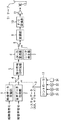
図2は、本発明を適用した磁気テープ記録再生装置の記録系の構成例を表している。映像データ圧縮部1は、入力されたHD映像信号を、MP@HLあるいはMP@H-14などのMPEG方式で圧縮する。
【0031】
音声データ圧縮部2は、HD映像信号に対応する音声信号を、例えば、MPEG1 layer2あるいはAACに準拠した方式などの音声圧縮を行う。これにより、音声信号は、256Kbps乃至384Kbpsに圧縮される。
【0032】
端子3には、AUX(補助)データや、サブコードデータなどで構成されるシステムデータが、コントローラ13から入力される。システムデータとは、映像、音声の付加データとして外部から入力された著作権、撮影状況等のテキスト情報、サーチや編集等を補助するタイトルタイムコード(TTC)、トラック位置情報、装置の設定情報などを示すデータである。
【0033】
スイッチ4は、コントローラ13により切り換えられ、映像データ圧縮部1の出力、音声データ圧縮部2の出力、または端子3から供給されるシステムデータを所定のタイミングで適宜選択し、誤り符号ID付加部5に供給する。
【0034】
誤り符号ID付加部5は、スイッチ4を介して入力されたデータに、誤り検出訂正符号やIDを付加したり、16トラックの間でのインタリーブ処理を施し、24−25変換部6に出力する。
【0035】
24−25変換部6は、トラッキング用のパイロット信号の成分が強くでるように選ばれた冗長な1ビットを付加することで、入力された24ビット単位のデータを、25ビット単位のデータに変換する。
【0036】
シンク発生部7は、後述するメインデータ(図9)またはサブコード(図22)に付加するシンクデータ、並びにアンブルのデータを発生する。
【0037】
スイッチ8はコントローラ13により制御され、24−25変換部6の出力またはシンク発生部7の出力の一方を選択し、変調部9に出力する。
【0038】
変調部9は、スイッチ8を介して入力されたデータを、1または0が連続しないようにランダマイズするとともに、磁気テープ21に記録するのに適した方式(DVフォーマットにおける場合と同一の方式)で変調し、パラレルシリアル(P/S)変換部10に供給する。
【0039】
パラレルシリアル変換部10は、入力されたデータを、パラレルデータからシリアルデータに変換する。
【0040】
増幅器11は、パラレルシリアル変換部10より入力されたデータを増幅し、回転ドラム(図示せず)に取り付けられ、回転される回転ヘッド12に供給し、磁気テープ21に記録させる。
【0041】
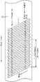
図3は、磁気テープ21に、回転ヘッド12により形成されるトッラクのフォーマットを表している。回転ヘッド12は、図中右下から、左上方向に、磁気テープ21をトレースすることで、磁気テープ21の長手方向に対して傾斜したトラックを形成する。磁気テープ21は、図中、右から左方向に移送される。
【0042】
各トラックは、そこに記録されるトラッキング制御のためのパイロット信号の種類に応じて、F0,F1またはF2のいずれかとされる。トラックはF0,F1,F0,F2,F0,F1,F0,F2の順に形成される。
【0043】
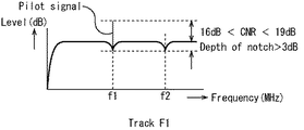
トラックF0には、図4に示すように、周波数f1,f2のパイロット信号がいずれも記録されていない。これに対してトラックF1に、図5に示すように、周波数f1のパイロット信号が記録されており、トラックF2には、図6に示すように、周波数f2のパイロット信号が記録されている。
【0044】
周波数f1,f2は、それぞれチャネルビットの記録周波数の1/90または1/60の値とされている。
【0045】
図4に示すように、トッラクF0の周波数f1,f2におけるノッチ部の深さは、9dBとされている。これに対して、図5または図6に示すように、周波数f1、または周波数f2のパイロット信号のCNR(Carrier to Noise Ratio)は、16dBより大きく、19dBより小さい値とされる。そしてその周波数f1,f2のノッチ部の深さは、3dBより大きい値とされる。
【0046】
この周波数特性を有するトラックパターンは、DVフォーマットと同様のトラックパターンである。また、記録レートは、1秒間に300トラックとする約40Mbpsである。従って、民生用デジタルビデオテープレコーダの磁気テープ、回転ヘッド、駆動系、復調系、制御系が、この実施の形態においても、そのまま利用することができる。
【0047】
また、各トラックには、トラックペア番号が設定されている。トラックペア番号は、トラックペアとされる、プラス側のアジマスとマイナス側のアジマスの2つのヘッドにより走査される2つのトラックに与えられる番号である。図3の例では、0番乃至31番のトラックペア番号が与えられ、インタリーブされる16トラックの先頭のトラックペアには、0番、8番、16番、または24番(16番および24番が設定されたトラックペアは図示されていない)のトラックペア番号が設定される。
【0048】
図7は、各トッラクのセクタフォーマット(セクタ配置)の例を示している。なお、図7において、各部の長さのビット数は、24−25変換後の長さで表されている。1トラックの長さは、回転ヘッド12が、60×1000/1001Hzの周波数で回転されるとき、134975ビットとされ、60Hzの周波数で回転されるとき、134850ビットとされる。1トラックの長さとは、磁気テープ21の174度の巻き付け角に対応する長さであり、その後ろには、1250ビットのオーバーライトマージンが形成される。このオーバーライトマージンは、消し残りを防止するものである。
【0049】
図7において、回転ヘッド12は、左から右方向にトッラクをトレースする。その先頭には、1800ビットのプリアンブルが配置されている。このプリアンブルにはクロックを生成するのに必要な、例えば、図8に示すようなパターンAとパターンBに示すデータが組み合わされて記録される。パターンAとパターンBは、それぞれの0と1の値が逆になったパターンとされている。このパターンを適当に組み合わせることにより、図4乃至図6に示すトラックF0,F1,F2のトラッキングパターンを実現することができる。なお、この図8のランパターンは、図2の24−25変換部6により24−25変換された後のパターンを表している。
【0050】
1800ビットのプリアンブルの次には、130425ビットの長さのメインセクタが配置されている。このメインセクタの構造は図9に示されている。このメインセクタは、通常再生およびサーチ再生される。
【0051】
同図に示すように、メインセクタは141個のシンクブロックで構成され、各シンクブロックの長さは、888ビット(111バイト)とされる。
【0052】
最初の123個のシンクブロックは、16ビットのシンク、24ビットのID、8ビットのシンクブロック(SB)ヘッダ、760ビットのメインデータ、そして80ビットのパリティC1とされる。
【0053】
シンクは、シンク発生部7により発生される。
【0054】
IDは、図10(A)に示すように、それぞれ1バイトの長さの、3つのID0乃至ID2から構成されている。
【0055】
ID0のb7乃至b0のうち、b7乃至b5には、トラックのフォーマットタイプが定義され、b4乃至b0には、トラックペア番号が示されている。
【0056】
トラックフォーマットは、図7に示したものの他、例えば、ITIセクタがさらに設けられ、メインセクタが139シンクブロックからなるフォーマットや、ITIセクタおよび7個のシンクブロックのアフレコ用セクタがさらに設けられ、メインセクタが129シンクブロックからなるフォーマットなどを利用することもできる。すなわち、ID0のb7乃至b5には、利用可能なフォーマットを識別するためのID等が配置される。このようにして、トラックフォーマットを識別することができるようにしておくことより、フォーマットに適応した復調処理を実行することができ、データを適切に再生することが可能となる。
【0057】
ID1には、シンクブロック番号が配置される。
【0058】
ID2には、メインセクタに記録されているデータが、新規に記録されたものか(何も記録されていないところにはじめて記録されたものか)、または上書き記録されたものか(何らかのデータにオーバーライトされたものか)を示す情報が、オーバーライトプロテクトとして配置される。例えば、上書き記録をする場合において、下地データが、ヘッドの瞬時クロッグ等により残っていたとき、新たに記録されるデータが、そのパリティC1が成立することより、訂正(誤訂正)される。そこで、それを防止するために、このオーバーライトプロテクトにより、新たに記録されたデータとの区別し、例えば、下地データと判断されたとき、このシンクブロックを全て無効(バーストエラー扱い)として、パリティC2によりイレージャ訂正を行うことができる。
【0059】
図10(B)は、141シンクブロックのそれぞれに含まれるID0乃至ID2を表している。ID0乃至ID2は、誤り符号ID付加部5により付加される。
【0060】
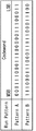
SBヘッダは、図11に示すように、b7乃至b0の8ビットで構成されている。b7乃至b0のうち、b7乃至b5には、メインデータの種類(例えば、音声データ、映像データ、サーチ用の映像データ、トランスポートストリームのデータ、AUXデータを示すデータ)を示す所定の値が設定され、b4乃至b0には、そのメインデータの詳細を示す所定の値が設定される。
【0061】
b7乃至b5における値0は、メインデータが、MPEG2に準拠したプログラムエレメンタリストリーム(PES)のフォーマットに準拠した映像データ(PES映像データ)であることを示し、値1は、PESのフォーマットに準拠した音声データ(PES音声データ)であることを示す。この場合、b4乃至b0のうち、b4には、データ(映像データまたは音声データ)が、パーシャル(95バイト未満)であるかフル(95バイト)であるかを示すデータが配置され、b3乃至b0には、カウント値を示すデータが配置される。
【0062】
b7乃至b5における値2は、メインデータが、サーチ用データであることを示す。この場合、b4乃至b0のうち、b4には、そのサーチ用データが映像データであるか音声データであるかを示すデータが配置される。また、b3乃至b1には、サーチ速度を示すデータが配置される。例えば、図12に示すように、b3乃至b1における値1は、4倍速を示し、値2は、8倍速を示し、値4は、16倍速を示し、そして値5は、32倍速を示す。なお、回転ヘッド(ドラム)の回転数を追従型にすることによって、各倍速の適応速度(ドラム回転数に対応した速度)を広げたサーチが可能となる。また、サーチ用の映像データは、Iピクチャの高域成分を落とした、低ビットレートのデータである。
【0063】
図11に戻り、b7乃至b5における値3は、メインデータがAUX(補助)データであることを示す。この場合、b4乃至b0のうち、b4乃至b2には、例えば、図13に示すように、AUXデータの種類(AUXモード)を示すデータが配置される。
【0064】
すなわち、b4乃至b2における値0は、AUXデータが、PES映像データに関するAUXデータであること(図中、AUX-V)を示し、値1は、PES音声データに関するAUXデータであること(AUX-A)を示す。値2は、AUXデータが、トランスポートストリームの形態で記録されているもののうちの前半部分のデータに対応するPSI(プログラム仕様情報)であること(PES-PSI1)を示し、値3は、その後半部分のデータに対応するPSIであること(PES-PSI2)を示す。そして値4は、AUXデータが、図14,15に示すような、それぞれキーワード番号が設定されている所定のデータ(システムデータと称する)であること(System)を示す。なお、詳細は後述するが、図14は、そのデータ量が固定のシステムデータを示しており、図15は、そのデータ量が可変するシステムデータを示している。
【0065】
図11に再度戻り、b7乃至b5における値4は、メインデータがトランスポートストリームの形態で記録されているもののうちの前半部分であることを示す。この場合、b4,b3には、ジャンプフラグが配置され、b2乃至b0には、タイムスタンプが配置される。また、b7乃至b5における値5は、メインデータがトランスポートストリームの形態で記録されているもののうちの後半部分であることを示す。この場合の、b4乃至b0には、カウント値が配置される。
【0066】
b7乃至b5における値6は、メインデータとして何のデータも記録されていないことを示す。すなわち、NULLを示す。このNULLは、メインデータの平均総量が記録可能レートより少ない時に挿入される。例えば、トランスポートストリーム記録でレートが20Mbpsの場合、約5Mbps分のNULLが挿入される。
【0067】
上述したSBヘッダのデータは、端子3から、コントローラ13より供給される。
【0068】
メインセクタのメインデータは、映像データ圧縮部1より供給される映像データ、音声データ圧縮部2より供給される音声データ、若しくは端子3を介してコントローラ13から供給されたAUXデータ(システムデータ)である。
【0069】
ここで、システムデータ(SBヘッダのb7乃至b5に、値3で設定され、かつ、b4乃至b2に値0(AUX-V)、値1(AUX-A)、または値4(System)が設定されたメインセクタにメインデータとして記録されるAUXデータ)のパケット構造について説明する。
【0070】
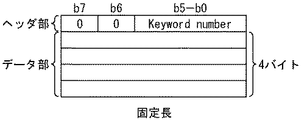
システムデータは、図14に示すような固定長のものである場合、図16(A)に示すように、キーワード番号などを含むヘッダ部(1バイトのキーワード)と、そのキーワード番号に対応するシステムデータを格納するデータ部(固定長(4バイト))から構成される。また、システムデータが、図15に示すような可変長のものである場合、図17(A)に示すように、ヘッダ部(1バイトのキーワード)、データ長を示すデータ長部(1バイト)、およびデータ部(可変長(nバイト))から構成される。
【0071】
また、この例の場合、複数のシステムデータをメインセクタに記録することもできる。この場合、システムデータが固定長であるときは、図16(B)乃至(D)に示すように、また、可変長であるときは、図17(B)乃至(D)に示すように、複数のヘッダ部が設けられる。
【0072】
ヘッダ部の1バイト(b7乃至b0の8ビット)のうち、b7には、他のヘッダ部が続いて配置されるか否かを示すデータが配置される。例えば、図16の例での、ヘッダ部F1(図16(A))、ヘッダ部F12(図16(B))、ヘッダ部F23(図16(C))、またはヘッダ部FK(図16(D))のように、また図17の例での、ヘッダ部X1(図17(A))、ヘッダ部X12(図17(B))、ヘッダ部X23(図17(C))、またはヘッダ部XK(図17(D))のように、次に、他のヘッダ部が配置されていないヘッダ部のb7には、値0が設定される。
【0073】
一方、図16の例での、ヘッダ部F11、ヘッダ部F21,F22、またはヘッダ部F31・・・(ヘッダ部FKを除く)のように、また、図17の例での、ヘッダ部X11、ヘッダ部X21,X22、またはヘッダ部X31・・・(ヘッダ部XKを除く)のように、次に、他のヘッダ部が配置されるヘッダ部のb7には、値1が設定される。
【0074】
また、ヘッダ部のb7乃至b0のうち、b6乃至b0に配置されるデータは、先頭に配置されるヘッダ部(図16の例では、ヘッダ部F1、ヘッダ部F11、ヘッダ部F21、またはヘッダ部F31、図17の例では、ヘッダ部X1、ヘッダ部X11、ヘッダ部X21、またはヘッダ部X31)と、2番目以降に配置されるヘッダ部(図16の例では、ヘッダ部F12、ヘッダ部F22,F23、またはヘッダ部F32乃至FK、図17の例では、ヘッダ部X12、ヘッダ部X22,X23、またはヘッダ部X32乃至XK)で異なる。
【0075】
先頭に配置されるヘッダ部の、b6乃至b0のうち、b6には、システムデータが固定長であるか可変長であるかを示すデータが配置される。すなわち、図16におけるヘッダ部F1、ヘッダ部F11、ヘッダ部F21、またはヘッダ部F31のb6には、固定長であることを示す値0が設定され、図17における、ヘッダ部X1、ヘッダ部X11、ヘッダ部X21、またはヘッダ部X31のb6には、可変長であることを示す値1が設定される。
【0076】
先頭に配置されるヘッダ部の、残りのb5乃至b0には、図14に示すキーワード番号(0番乃至63番)、すなわち、固定長のシステムデータのキーワード番号が設定される。
【0077】
一方、2番目以降の配置されるヘッダ部の場合、そのb6乃至b0には、図15に示すキーワード番号(64番乃至127番)、すなわち、可変長のシステムデータの番号が設定される。
【0078】
図18は、上述した、先頭のヘッダ部(図18(A))および2番目以降のヘッダ部(図18(B)))のb7乃至b6に配置されるデータをまとめて示している。
【0079】
図19は、固定長のシステムデータ(図14,16)を、図20は、可変長のシステムデータ(図15,17)を、ビット配列に対応して表したものである。
【0080】
なお、上述したシステムデータは、後述するサブコードセクタにサブコードデータとしても記録される。
【0081】
パリティC1(図9)は、各シンクブロックごとに、ID、SBヘッダ、およびメインデータから、誤り符号ID付加部5において計算され、付加される。
【0082】
141シンクブロックのうちの最後の18シンクブロックは、シンク、ID、パリティC2およびC1とされる。パリティC2は、図9において、SBヘッダまたはメインデータを、それぞれ縦方向に計算することで求められる。この演算は、誤り符号ID付加部5において行われる。なお、18シンクブロックにすることより、パリティC2のシンクブロックの数の割合が、シンクブロックの数(141)に対して、12.7%(=18/141)となり、連続エラーの訂正能力を2トラック以上にするために必要な比率(12.5%(=2トラック/16トラック))より大きくすることができる。
【0083】
図21は、24−25処理前の、メインデータとして記録されるAUXデータ、映像データ、音声データ、サーチデータ、パリティC1、およびパリティC2の平均値を表している。
【0084】
AUXデータ、映像データ、音声データ、そしてサーチデータに対する平均値としてのシンクブロック数は、それぞれ、7.5シンクブロック、113シンクブロック、1.75シンクブロック、そして7.5シンクブロックとなる。すなわち、平均値としてのビットレートは、下記のように求められる。
AUXデータ=95バイト×0.75SB×300トラック×8ビット=171kbps
映像信号=95バイト×113SB×300トラック×8ビット=25.764Mbps
音声信号=95バイト×1.75SB×300トラック×8ビット=339kbps
サーチデータ=95バイト×7.5SB×300トラック×8ビット=1710kbps
結局、その合計は、28.044(=171kbps+25.764Mbps+339kbps+1710kbps)Mbps
となり、MP@HLまたはMP@H-14によるHD映像データ、音声圧縮データ、AUXデータ、サーチ用の映像データを記録するのに充分なレートとなる。なお、95バイトは、1シンクブロックにおけるSBヘッダとメインデータのデータ量である。
【0085】
メインセクタの次には、1250ビットのサブコードセクタ(図7)が配置されている。このサブコードセクタの構成は、図22に示されている。
【0086】
1トラックのサブコードセクタは、1250ビットの長さ(24−25変換後の長さ)で、10個のサブコードシンクブロックで構成されている。
【0087】
1サブコードシンクブロックは、16ビットのシンク、24ビットのID、40ビットのサブコードデータ、および40ビットのパリティにより構成されている。すなわち、1サブコードシンクブロックの長さは、120ビット(24−25変換される前の値)であり、上述したメインセクタの1シンクブロックの長さ(888ビット)に対して、約1/7の長さである。このように、データ長さを短くすることより、例えば、200倍速程度の高速再生においても、サブコードシンクブロックの内容を確実に読み取ることができるようになり、高速サーチが可能となる。
【0088】
シンクは、メインセクタに付加されるシンクとは異なるものであり、このシンクにより、メインセクタとサブセクタを識別することができる。また、シンクは、図2のシンク発生部7により付加される。
【0089】
シンクブロックのIDは、図23(A)に示すように、1バイト毎の、3つのID0乃至ID2から構成されている。
【0090】
ID0には、図10(A)のメインセクタのID0と同じように、フォーマットタイプおよびトラックペア番号がそれぞれ定義されている。
【0091】
ID1のb7乃至b0のうち、b3乃至b0には、サブコードシンクブロックの番号が配置される。b7乃至b4は、予備ビットである。
【0092】
シンクブロック番号は、1トラックのサブコードセクタに含まれる10個のサブコードシンクブロックのそれぞれに与えられる、0番乃至9番の番号である。
【0093】
ID2には、メインセクタにおけるID2と同様に、オーバーライトプロテクトが配置される。なお、サブコードセクタにおいては、このID2に、記録されているデータが、下地のものであることが示されている場合、シンクブロックを全て無効にして(取得できなかったものとして)処理が実行される。
【0094】
図23(B)は、10のサブコードシンクブロックに含まれるID0乃至ID2が示されている。ID0乃至ID2は、誤り符号ID付加部5により付加される。
【0095】
サブコードシンクブロックのIDの次に配置されているサブコードデータは、図14に示した、いわゆる固定長のシステムデータとされる。すなわち、図16,19に示したような形態で、記録される。また、サブコードデータは、例えば、ユーザテープの場合とPre-RECテープの場合で、その種類が異なる。ユーザテープの場合は、図24(A)に示すように、テープ位置情報(ATNF)、タイトルタイムコード(TTC)、記録年月日、または記録時間がサブコードデータとされ、Pre-RECテープの場合は、図24(B)に示すように、テープ位置情報、タイトルタイムコード、パート番号、またはチャプター開始位置がサブコードデータとされる。すなわち、Pre-RECテープの場合、ユーザテープの場合における記録年月日に代えて、パート番号が、そして記録時刻に代えて、チャプター開始位置がサブコードデータに含まれる。
【0096】
サブコードデータは、図2の端子3を介して、コントローラ13から供給される。
【0097】
図25は、DVフォーマット(従来)のサブコードシンクのID、およびサブコードデータのデータ構成を示している。本発明において記録されるデータ位置情報(ATNF中のEPO)等が記録されるようになされていない。
【0098】
サブコードデータの次には、40ビットのパリティが付加されている。このパリティは、誤り符号ID付加部5により付加されるものである。
【0099】
サブコードセクタの次には、ポストアンブル(図7)が配置される。このポストアンブルも、図8に示したパターンAとパターンBを組み合わせることで記録される。その長さは、60×1000/1001Hzに同期するとき1500ビットとされ、50Hzに同期するとき1375ビットとされる。
【0100】
次に、図14および図15に示したシステムデータについて、詳細に説明する。
【0101】
図14には、上述したように、固定長のシステムデータが、キーワード番号とともに示されている。例えば、キーワード番号が4番のテープ位置情報(ATNF)は、23ビットの絶対位置(ATN)、1ビットのブレークフラグ(Bフラグ)、および8ビットの編集情報からなる固定長のシステムデータである。
【0102】
絶対位置(ATN)は、トラックの、テープ先頭からの距離(絶対位置)(Absolute Track number)を示す。
【0103】
Bフラグは、絶対位置(例えば、番号)が連続しているときに”0”が立ち、連続していないときに”1”が立つフラグである。このことより、記録が混在し、絶対位置が連続していない場合においても、単調増加の番号を付与することができるようになる。すなわち、番号戻りがないので、サーチを的確に行うことができる。
【0104】
編集情報は、図26に示すように、b7乃至b0の8ビットで構成されている。b7には、Iフラグが配置されている。Iフラグは、サブコードセクタに対応するメインセクタに、サーチしたい場所を示す情報(記録時に指定されている場所を示す情報)が含まれているとき、”1”が立つフラグである。これにより、サーチ位置が検出される。
【0105】
b5には、Pフラグが配置されている。このPフラグは、サブコードセクタに対応するメインセクタに、静止画の記録開始映像データが含まれている場合に、”1”が立つフラグである。これにより、静止画の記録位置が検出される。
【0106】
b4には、EHフラグが配置されている。EHフラグは、サブコードセクタに対応するメインセクタに、IピクチャまたはPピクチャが記録されているとき、”1”が立つフラグである。通常、繋ぎ撮り等の編集は、IピクチャやPピクチャから開始されるので、このEHフラグにより、編集位置を検出することができる。
【0107】
残りのb3乃至b0には、エディットピクチャヘッダオフセット(EPO)が配置されている。このEPOは、サブコードセクタが対応するメインセクタの位置を、16トラックを1単位として示す。図27を参照して、EPOについてさらに説明する。図27の例では、TTCが値0とされているサブコードセクタについてのEPOは値5であり、またそのサブコードセクタは、ECC番号(16トラック毎の番号)が番号6の所定のトラックに配置されている。つまり、このサブコードセクタに対応するメインセクタは、サブコードセクタが配置されているトラックより、EPOの値5×16トラック分だけ先行するトラックに配置されていることがわかる。これにより、編集点とされるIピクチャやPピクチャが、実際にどこのメインセクタに記録されているかを検出することができる。
【0108】
以上に説明したシステムデータは、上述したように、メインセクタおよびサブコードセクタに、記録される。
【0109】
次に、図15に示す可変長のAUXデータについて説明する。なお、このAUXデータは、メインセクタにのみに記録される。
【0110】
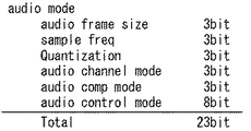
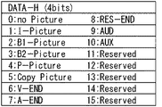
例えば、キーワード番号が、80番のECCTB(トラックブロック)は、図28において○印で示されている、複数のAUXデータを含むパケットであり、そこには、図14に示される、固定長のAUXデータ(データ位置情報(ATNF)、TTCなど)なども含まれている。例えば、3バイトのオーディオモードとして、図29に示すように、オーディオフレームサイズ(3ビット)、サンプル周期(3ビット)などが含まれ、また、ビデオモードとして、図30に示すように、ビデオレート(24ビット)などのデータが含まれる。さらに、DATA-Hとして、図31に示すように、ピクチャの種類等を示す情報が含まれる。
【0111】
次に、図2の装置の動作について説明する。HD映像信号は、サーチ用の映像データ(サムネイルの映像データ)とともに、映像データ圧縮部1に入力され、例えば、MP@HLまたはMP@H-14方式で圧縮される。音声信号は、音声データ圧縮部2に入力され、圧縮される。端子3には、コントローラ13から、サブコードデータ、AUXデータ、ヘッダなどが供給される。
【0112】
スイッチ4は、コントローラ13により制御され、映像データ圧縮部1より出力された映像データ(サーチ用の映像データを含む)、音声データ圧縮部2より出力された音声データ、あるいは、端子3から入力されたシステムデータを、所定のタイミングで取り込み、誤り符号ID付加部5に出力することでこれらのデータを合成する。
【0113】
誤り符号ID付加部5は、メインセクタの図9に示す各シンクブロックに、24ビットのIDを付加する。また、図9に示すパリティC1を、各シンクブロック毎に計算し、付加するとともに、141シンクブロックのうちの最後の18シンクブロックには、SBヘッダとメインデータの代わりに、パリティC2を付加する。
【0114】
また、誤り符号ID付加部5は、図22に示すように、サブコードデータの各サブコードシンクブロック毎に、24ビットのIDを付加するとともに、40ビットのパリティを演算し、付加する。
【0115】
誤り符号ID付加部5は、さらに、メインセクタの16トラック分のデータを保持し、それらのデータを16トラックの間でインタリーブする。
【0116】
24−25変換部6は、誤り符号ID付加部5より供給された24ビット単位のデータを、25ビット単位のデータに変換する。これにより、図4乃至図6に示した、周波数f1,f2のトラッキングのパイロット信号の成分が強く出現するようになる。
【0117】
シンク発生部7は、図9に示すように、メインセクタの各シンクブロックに、16ビットのシンクを付加する。また、シンク発生部7は、図22に示すように、サブコードセクタの各サブコードシンクブロックに、16ビットのシンクを付加する。さらに、シンク発生部7は、図8に示すプリアンブルまたはポストアンブルのランパターンを発生する。
【0118】
これらのデータの付加(合成)は、より具体的には、コントローラ13が、スイッチ8を切り換え、シンク発生部7から出力されたデータと、24−25変換部6が出力したデータを、適宜選択して変調部9に供給するようにすることで行われる。
【0119】
変調部9は、入力されたデータを、ランダマイズするとともに、DVフォーマットに対応する方式で変調し、パラレルシリアル変換部10に出力する。パラレルシリアル変換部10は、入力されたデータをパラレルデータからシリアルデータに変換し、増幅器11を介して、回転ヘッド12に供給する。回転ヘッド12は、入力されたデータを磁気テープ21に記録する。
【0120】
図32は、以上のようにして処理された結果、磁気テープ21に記録されている、GOP構造がN=15(15ピクチャ毎にIピクチャが配列される)、M=3(3ピクチャ毎にPピクチャが配置される)データの記録状態を示している。すなわち、Mの値で示される数分のピクチャを1つの単位として、そのピクチャに関連するAUXデータ(図中、Uで示されている部分)、そのピクチャに対応する音声データ(図中、Aで示されている部分)、およびその音声データに関連するAUXデータ(図中、Xで示されている部分)が、インタリーブされる16トラックの先頭にまとめて配置されている。そして、その後に、1単位分のピクチャ(この例の場合、3ピクチャ)が配置されている。
【0121】
すなわち、可変長のAUXデータを用意し、それをメインセクタに記録するようにしたので、このようにAUXデータを、所定の単位分のピクチャ毎にまとめて 記録することができ、その結果、効率よくAUXデータを記録することができる。
【0122】
また、サブコードセクタに、そこに記録されているAUXデータ(固定長のデータ)に対応するメインセクタまでの距離を示したEPOを記録するようにしたので、容易に対応するメインセクタを検出することができる。
【0123】
例えば、図33は、目的とするTTCの値を、EPOで補正し、その値を利用して、対応するメインセクタを検出する場合の例を示している。
【0124】
EPOは、下記に式で求めることができる。
EPO=編集点のサブコード_TTCの記録トラック番号/16−
サブコード_TTCに該当するメインPIC_TTCの記録トラック番号/16
【0125】
1/16は、ECCブロック番号に変換させるためのである。また、サブコード_TTCは、10トラックで同じデータが記録されているため平均フレーム単位にオフセット値を求める。
【0126】
これにより、サーチ走行中事前(該当TTCに達したとき)に目標位置を検出することができる。なお、この場合、オフセットのヒストリ情報が必要になる(プリ再生を短くするためにはECCTBを用意する必要がある)。
【0127】
また、インタリーブされる16トラックの先頭に、AUXデータとしてのECCTB(図中、Hで示されている部分)を配置するようにしたので、例えば、繋ぎ撮りで行われるプリ再生時間を短くすることができる。つまり、本来プリ再生に必要なAUXデータは、サブコードセクタに記録されているが、上述したように、サブコードセクタは、対応するメインセクタに対して時間的に遅れて配置されているので、それを参照すれば、その分だけ多くの時間がかかってしまう。
【0128】
図34は、ピクチャに関連するAUXデータ(U)と音声データに関するAUXデータ(X)、ECCTB、およびサブコードに含まれるデータをまとめたものである。
【0129】
図35は、別方式でEPOを生成する例である。この例の場合、EPOは、下記の式で求めることができる。
【0130】
EPO=ECC内のトラック先頭(=サブコード_TTC−メインPIC_TTC) これにより、EPOのヒストリ情報が無くても繋ぎ記録することができる。なお、サーチ走行中、該当TTCに達した後オフセット補正をしたTTC(目標位置)に近づいて行く必要がある。
【0131】
また、図35の例では、TTCが値0とされているサブコードセクタは、ECC6(ECC番号が6番)のトラックT0に配置されている。つまり、ECC6のトラックT0から、9×16トラック分だけ遡ることで、対応するメインセクタが、ECC0のトラックT0に配置されていることを検出することができる。なお、ECC6の各トラックに配置されているサブコードセクタには、Iピクチャが記録されているメインセクタが対応しているので、EHヘッダには、”1”が立っている。
【0132】
図36は、以上のようにして、磁気テープ21に記録されたデータを再生する再生系の構成例を表している。
【0133】
回転ヘッド12は磁気テープ21に記録されているデータを再生し、増幅器41に出力する。増幅器41は入力信号を増幅し、A/D変換部42に供給する。A/D変換部42は、入力された信号をアナログ信号からデジタル信号に変換し、復調部43に供給する。復調部43は、A/D変換部42より供給されたデータを、図2の変調部9におけるランダマイズに対応してデランダマイズするとともに、図2の変調部9における変調方式に対応する方式で復調する。
【0134】
シンク検出部44は、復調部43により復調されたデータから、図9示すメインセクタの各シンクブロック毎のシンク、および図22に示すサブコードセクタの各サブコードシンクブロックのシンクを検出し、誤り訂正ID検出部46に供給する。25−24変換部45は、復調部43より供給されたデータを、図2の24−25変換部6における変換に対応して、25ビット単位から24ビット単位のデータに変換し、誤り訂正ID検出部46に出力する。
【0135】
誤り訂正ID検出部46は、シンク検出部44より入力されたシンクを基に、誤り訂正処理、ID検出処理、デインタリーブ処理を実行する。
【0136】
スイッチ47は、コントローラ13により制御され、誤り訂正ID検出部46より出力されたデータのうち、映像データ(サーチ用の映像データを含む)を映像データ伸長部48に出力し、音声データを音声データ伸長部49に出力し、サブコードデータ、AUXデータなどのシステムデータを、端子50からコントローラ13に出力する。
【0137】
映像データ伸長部48は、入力された映像データを伸長し、D/A変換して、アナログHD映像信号として出力する。音声データ伸長部49は、入力された音声データを伸長し、D/A変換して、アナログ音声信号として出力する。
【0138】
次に、その動作について説明する。回転ヘッド12は、磁気テープ21に、図32に示すような形態で記録されているデータを再生し、増幅器41により増幅させた後、A/D変換部42に供給する。A/D変換部42により、アナログ信号からデジタルデータに変換されたデータは、復調部43に入力され、図2における変調部9におけるランダマイズと変調方式に対応する方式でデランダマイズされるとともに復調される。
【0139】
25−24変換部45は、復調部43により復調されたデータを、25ビット単位のデータから24ビット単位のデータに変換し、誤り訂正ID検出部46に出力する。
【0140】
シンク検出部44は、復調部43より出力されたデータから、図9に示すメインセクタのシンク、あるいは、図22に示すサブコードセクタのシンクを検出し、誤り訂正ID検出部46に供給する。誤り訂正ID検出部46は、16トラック分のデータを記憶し、デインタリーブ処理を行うとともに、図9に示すメインセクタのパリティC1,C2を利用して、誤り訂正処理を行う。さらに誤り訂正ID検出部46は、メインセクタのSBヘッダを検出し、各シンクブロックに含まれているデータが、音声データ、映像データ、AUXデータ、サーチ用の映像データなどのいずれであるのかを判定する。
【0141】
誤り訂正ID検出部46はまた、図22に示すサブコードセクタのパリティを利用して、サブコードデータの誤り訂正処理を行うとともに、AUXデータのパケットキーワード(ヘッダ)を検出し、そのサブコードデータの内容を判定する。これにより、サブコードデータが、トラック番号を表すのか、タイムコード番号を表すのかなどが判ることになる。
【0142】
スイッチ47は、誤り訂正ID検出部46により検出されたSBヘッダに基づいて、映像データおよびサーチ用データを映像データ伸長部48に供給する。映像データ伸長部48は、入力されたデータを、図2の映像データ圧縮部1における圧縮方式に対応する方式で伸長し、映像信号として出力する。
【0143】
スイッチ47は、音声データを音声データ伸長部49に出力する。音声データ伸長部49は、図2の音声データ圧縮部2における圧縮方式に対応する方式で入力された音声データを伸長し、音声信号として出力する。
【0144】
スイッチ47はまた、誤り訂正ID検出部46より出力されたAUXデータ、サブコードデータなどを端子50から図示せぬコントローラに出力する。
【0145】
これにより、図32に示したように記録されていたデータが、各ピクチャおよび音声データが伸張される。
【0146】
なお、以上においては、磁気テープ21に記録された各ピクチャおよび音声データを伸張する場合を例として説明したが、それらを多重化して、MPEGデータを生成することもできる。
【0147】
上述した一連の処理は、ハードウエアにより実行させることもできるが、ソフトウエアにより実行させることもできる。一連の処理をソフトウエアにより実行させる場合には、そのソフトウエアを構成するプログラムが、専用のハードウエアに組み込まれているコンピュータ、または、各種のプログラムをインストールすることで、各種の機能を実行することが可能な、例えば汎用のパーソナルコンピュータなどに、記録媒体からインストールされる。
【0148】
この記録媒体は、図2、図36に示すように、磁気テープ記録再生装置本体とは別に、ユーザにプログラムを提供するために配布される、プログラムが記録されている磁気ディスク31(フロッピディスクを含む)、光ディスク32(CD-ROM(Compact Disk-Read Only Memory),DVD(Digital Versatile Disk)を含む)、光磁気ディスク33(MD(Mini-Disk)を含む)、もしくは半導体メモリ34などよりなるパッケージメディアにより構成されるだけでなく、装置本体に予め組み込まれた状態でユーザに提供される、プログラムが記録されているROMや、ハードディスクなどで構成される。
【0149】
なお、本明細書において、記録媒体に記録されるプログラムを記述するステップは、記載された順序に沿って時系列的に行われる処理はもちろん、必ずしも時系列的に処理されなくとも、並列的あるいは個別に実行される処理をも含むものである。
【0150】
【発明の効果】
以上の如く、本発明の磁気テープ記録装置、磁気テープ記録方法、および記録媒体のプログラムによれば、映像データ、音声データ若しくはサーチデータ、またはそのデータに関連する可変長の補助データの一方を第1のグループのデータとして、また第1のグループのデータに関連するサブコードを含むデータを第2のグループのデータとして、磁気テープのトラック上において、両者の間が離間せずに連続するように合成し、磁気テープに記録するために供給するようにしたので、HD映像信号のデータに代表される、データ量の多いデータを磁気テープ上にデジタル的に記録することが可能となる。
【0151】
本発明の磁気テープによれば、第1のグループのデータと第2のグループのデータを、トラック上において、両者の間が離間せずに連続するように記録するようにしたので、HD映像信号のデータに代表される容量の多いデータを記録した磁気テープを実現することが可能となる。
【0152】
本発明の磁気テープ再生装置、磁気テープ再生方法、および記録媒体のプログラムによれば、回転ヘッドにより磁気テープから再生されたデータから、第1のグループのデータとしての補助データを取得し、それに基づいて磁気テープから再生されたデータを処理するようにしたので、標準の映像データを、確実に再生することが可能となる。
【図面の簡単な説明】
【図1】 DVフォーマットのトラックセクタの構成を説明する図である。
【図2】本発明を適用した磁気テープ記録再生装置の記録系の構成例を示すブロック図である。
【図3】図2の磁気テープ21のトラックフォーマットを説明する図である。
【図4】図3のトラックに記録されるトラッキング用のパイロット信号を説明する図である。
【図5】図3のトラックに記録されるトラッキング用のパイロット信号を説明する他の図である。
【図6】図3のトラックに記録されるトラッキング用のパイロット信号を説明する他の図である。
【図7】図3のトラックのセクタ配置を説明する図である。
【図8】図7のプリアンブルとポストアンブルのパターンを説明する図である。
【図9】図7のメインセクタの構成を説明する図である。
【図10】図9のメインセクタのIDを説明する図である。
【図11】図9のメインセクタのSBヘッダを説明する図である。
【図12】サーチ速度を説明する図である。
【図13】 AUXデータの種類を示す図である。
【図14】固定長のシステムデータを説明する図である。
【図15】可変長のシステムデータを説明する図である。
【図16】固定長のシステムデータのフォーマットを説明する図である。
【図17】可変長のシステムデータのフォーマットを説明する図である。
【図18】ヘッダ部に定義される情報を説明する図である。
【図19】固定長のシステムデータのフォーマットを説明する他の図である。
【図20】可変長のシステムデータのフォーマットを説明する他の図である。
【図21】メインセクタに記録されるデータの平均値を説明する図である。
【図22】図7のサブコードセクタの構成を説明する図である。
【図23】サブコードシンクブロックのIDを説明する図である。
【図24】サブコードデータを説明する図である。
【図25】 DVフォーマットを説明する他の図である。
【図26】テープ位置情報を説明する図である。
【図27】 EPOを説明する図である。
【図28】 ECCTBを説明する図である。
【図29】オーディオモードを説明する図である。
【図30】ビデオモードを説明する図である。
【図31】 DATA-Hを説明する図である。
【図32】データの記録状態を説明する図である。
【図33】サブコードセクタに対応するメインセクタを検出する処理を説明する図である。
【図34】 AUXデータを説明する図である。
【図35】サブコードセクタに対応するメインセクタを検出する処理を説明する他の図である。
【図36】本発明を適用した磁気テープ記録再生装置の再生系の構成例を示すブロック図である。
【符号の説明】
1 映像データ圧縮部, 2 音声データ圧縮部, 5 誤り符号ID付加部,6 24−25変換部, 7 シンク発生部, 9 変調部, 21 磁気テープ, 43 復調部, 45 25−24変換部, 44 シンク検出部, 46 誤り訂正ID検出部, 48 映像データ伸長部, 49 音声データ伸長部[0001]
BACKGROUND OF THE INVENTION
The present invention relates to a magnetic tape recording apparatus and method, a magnetic tape reproducing apparatus and method,Magnetic tape,In particular, a magnetic tape recording apparatus and method, a magnetic tape reproducing apparatus and method, which can record or reproduce high-quality video data on a magnetic tape,Magnetic tape,And a recording medium.
[0002]
[Prior art]
Recently, with the progress of compression technology, video data and the like have been compressed by, for example, DV (Digital Video) method and recorded on a magnetic tape. The format for this is defined as the DV format for consumer digital video tape recorders.
[0003]
FIG. 1 shows the structure of one track in the conventional DV format. In the DV format, video data is 24-25 converted and recorded, but the number of bits shown in FIG. 1 represents a numerical value after 24-25 conversion.
[0004]
The range corresponding to the winding angle of 174 degrees of the magnetic tape is substantially the range of one track. Outside the range of one track, an overwrite margin having a length of 1250 bits is formed. This overwrite margin is for eliminating unerased data.
[0005]
The length of one track range is 134975 bits when the rotating head is rotated in synchronization with the frequency of 60 × 1000/1001 Hz, and 134850 bits when the rotating head is rotated in synchronization with the frequency of 60 Hz. It is said.
[0006]
In one track, an ITI sector, an audio sector, a video sector, and a subcode sector are sequentially arranged in the magnetic head trace direction (from left to right in FIG. 1), and there is a gap between the ITI sector and the audio sector. In G1, a gap G2 is formed between the audio sector and the video sector, and a gap G3 is formed between the video sector and the subcode sector.
[0007]
ITI (Insert and Track Information) sector is 3600 bits longTosaA 1400-bit preamble for generating a clock is arranged at the head, and next, an SSA (Start Sync Area) and a TIA (Track Information Area) are provided for a length of 1920 bits. In SSA, a bit string (sync number) necessary for detecting the position of TIA is arranged. In the TIA, information indicating that it is a DV format for consumer use, information indicating that it is in SP mode or LP mode, information indicating a pattern of a pilot signal of one frame, and the like are recorded. Next to the TIA, a 280-bit postamble is arranged.
[0008]
The length of the gap G1 is 625 bits.
[0009]
The audio sector has a length of 11550 bits, the first 400 bits and the last 500 bits are respectively a preamble or a postamble, and 10650 bits therebetween are data (audio data).
[0010]
The gap G2 is 700 bits long.
[0011]
The video sector is 113225 bits, the first 400 bits and the last 925 bits are respectively a preamble or a postamble, and 111900 bits therebetween are data (video data).
[0012]
The length of the gap G3 is 1550 bits.
[0013]
The subcode sector is 3725 bits when the rotating head is rotated at a frequency of 60 × 1000/1001 Hz, and 3600 bits when rotated at a frequency of 60 Hz. The first 1200 bits are the preamble and the last 1325 bits (when the rotating head is rotated at a frequency of 60 × 1000/1001 Hz) or 1200 bits (when the rotating head is rotated at a frequency of 60 Hz) 1,200 bits in between are used as data (subcode).
[0014]
[Problems to be solved by the invention]
In the DV format, gaps G1 to G3 are formed between the ITI sector, the audio sector, the video sector, and the subcode sector as described above, and a preamble and a postamble are provided for each sector. And so-called overheadManyHowever, there is a problem that a substantial data recording rate cannot be obtained.
[0015]
As a result, for example, in order to record high-definition video data (hereinafter referred to as HD (High Definition) video data), a bit rate of about 25 Mbps is required. In this recording format, MPEG (Moving Picture Expert) Group) MP @ HL video rate is at most excluding search image data24Only about Mbps can be secured. As a result, even though standard quality video data (hereinafter referred to as SD (Standard Definition) video data) can be recorded, HD video data is MP @ HL, MP @ H-14 format. Compress and record withRukoThere was a problem that could not be done.
[0016]
The present invention has been made in view of such a situation, and makes it possible to record or reproduce HD data.
[0017]
[Means for Solving the Problems]
The magnetic tape recording apparatus according to the present invention includes a first acquisition unit that acquires at least one of video data, audio data, and search data, and variable-length auxiliary data related to the data acquired by the first acquisition unit. Second acquisition means for acquiring the data, selection means for selecting at least one of the data acquired by the first acquisition means and the second acquisition means as data of the first group, and A third acquisition means for acquiring a second group of data including a sub-code associated with the data, and the first group of data and the second group of data on the magnetic tape track between the two; Combining means for synthesizing so as to be continuous without separation, and supply means for supplying the data synthesized by the synthesizing means to the rotary head for recording on the magnetic tapeThe second obtaining means obtains auxiliary data relating to audio data and auxiliary data relating to video data as the second group of data, and the synthesizing means is further divided into a plurality of tracks on the magnetic tape. The auxiliary data related to the video data of the picture for the unit and the auxiliary data related to the audio data corresponding to the picture for the unit are predetermined among the plurality of tracks. The data of the first group and the data of the second group are synthesized in each of the plurality of tracks so as to be arranged on the other track.
The synthesizing means further includes the first group of data and the first group of data so that the preamble and the postamble are arranged on the magnetic tape track with the set of the first group of data and the second group of data interposed therebetween. The two groups of data, preamble, and postamble are combined.
The synthesizing means includes information indicating data included in the first group data among the video data, the audio data, and the search data in the first group data, and includes the first group data and the first data. Two groups of data are combined.
[0018]
The first acquisition unit can acquire video data as the first group of data in edit units.
[0019]
The second acquisition means acquires auxiliary data related to audio data and auxiliary data related to video data as the second group of data, and the synthesis means uses auxiliary data related to audio data, audio data, auxiliary data related to video data, Then, combine them so that they are arranged in the order of the video data.The
[0020]
The second acquisition unit can further acquire auxiliary data necessary for pre-playback, and the synthesizing unit can synthesize auxiliary data required for pre-playback so as to be arranged at the head of the editing unit of the video data. .
[0021]
The auxiliary data necessary for pre-playback includes the content recorded in the subcode sector.Mu
[0022]
The magnetic tape recording method of the present invention includes a first acquisition step of acquiring at least one of video data, audio data, and search data, and a variable length related to the data acquired in the processing of the first acquisition step. A second acquisition step of acquiring auxiliary data; a selection step of selecting at least one of the data acquired in the processing of the first acquisition step and the processing of the second acquisition step as data of the first group; A third acquisition step of acquiring a second group of data including a subcode related to the first group of data; and the first group of data and the second group of data on a track of the magnetic tape , A synthesis step for synthesizing the two so as to be continuous without being separated, and data synthesized by the processing of the synthesis step are recorded on the magnetic tape. Containing a supply step of supplying to the rotary head in orderIn the second acquisition step, auxiliary data related to audio data and auxiliary data related to video data are acquired as data of the second group, and further divided in a plurality of tracks on the magnetic tape in the synthesis step. The auxiliary data related to the video data of the picture for the unit and the auxiliary data related to the audio data corresponding to the picture for the unit are predetermined among the plurality of tracks. The data of the first group and the data of the second group are combined in each of the plurality of tracks so as to be arranged on the tracks of the first track..
[0023]
The recording medium program of the present invention includes a first acquisition step for acquiring at least one of video data, audio data, and search data, and a variable length related to the data acquired in the processing of the first acquisition step. A second acquisition step of acquiring auxiliary data; a selection step of selecting at least one of the data acquired in the processing of the first acquisition step and the processing of the second acquisition step as data of the first group; A third acquisition step of acquiring a second group of data including a subcode related to the first group of data; and the first group of data and the second group of data on a track of the magnetic tape , And a synthesis step for synthesizing the two so that they are not separated from each other, and data synthesized by the processing of the synthesis step is recorded on the magnetic tape. Containing a supply step of supplying to the rotary head forIn the second acquisition step, auxiliary data related to audio data and auxiliary data related to video data are acquired as data of the second group, and further divided in a plurality of tracks on the magnetic tape in the synthesis step. The auxiliary data related to the video data of the picture for the unit and the auxiliary data related to the audio data corresponding to the picture for the unit are predetermined among the plurality of tracks. The data of the first group and the data of the second group are combined in each of the plurality of tracks so as to be arranged on the tracks of the first track..
[0024]
The magnetic tape of the present invention includes at least one first group of data of video data, audio data or search data, and variable length auxiliary data related to video data, audio data or search data, and first data The second group of data including subcodes related to the group of data is recorded on the track so as to be continuous without being separated from each other.Auxiliary data relating to video data as data of the second group of pictures for each unit, with a predetermined number of pictures divided and arranged on a series of tracks on the magnetic tape as one unit, In each of the plurality of tracks, the auxiliary data related to the audio data as the second group of data corresponding to the unit of picture is arranged on a predetermined track of the plurality of tracks. Group data and second group data are recorded.
[0025]
In the magnetic tape recording apparatus, magnetic tape recording method, and recording medium program of the present invention,At least one of video data, audio data, and search data is acquired, variable-length auxiliary data related to the acquired data is acquired, and at least one of the acquired data is data of the first group A second group of data is selected, including a subcode associated with the first group of data, and the first group of data and the second group of data are both stored on the magnetic tape track. The data is synthesized so as to be continuous without being separated, and the synthesized data is supplied to the rotary head for recording on the magnetic tape. As the second group of data, auxiliary data related to audio data and auxiliary data related to video data are acquired. In data composition, a predetermined number of pictures divided and arranged on a plurality of tracks on a magnetic tape are used as one unit, and auxiliary data related to video data of a unit of picture and a unit of picture. The first group data and the second group data are combined in each of the plurality of tracks so that the auxiliary data related to the corresponding audio data is arranged on a predetermined track of the plurality of tracks. The
[0026]
In the magnetic tape reproducing apparatus of the present invention, the high-definition or standard video data, audio data or search data, and variable length auxiliary data relating to the video data, audio data or search data are compressed on the magnetic tape. Data of at least one of the first group and data of a second group including a subcode related to the first group of data are continuously arranged on the track without being separated from each other. Recorded inAuxiliary data relating to video data as data of the second group of pictures for each unit, with a predetermined number of pictures divided and arranged on a series of tracks on the magnetic tape as one unit, In each of the plurality of tracks, the auxiliary data related to the audio data as the second group of data corresponding to the unit of picture is arranged on a predetermined track of the plurality of tracks. Group data and second group data are recorded,Acquisition means for acquiring auxiliary data as data of the first group or data of the second group from data reproduced from the magnetic tape by the rotary head, and auxiliary data or second group acquired by the acquisition means And decompressing means for decompressing compressed high-quality video data out of the data reproduced from the magnetic tape by the rotary head.
[0027]
In the magnetic tape reproducing method of the present invention, compressed high-quality or standard video data, audio data or search data, and variable-length auxiliary data related to video data, audio data or search data are included in the magnetic tape. Data of at least one of the first group and data of a second group including a subcode related to the first group of data are continuously arranged on the track without being separated from each other. Recorded inAuxiliary data relating to video data as data of the second group of pictures for each unit, with a predetermined number of pictures divided and arranged on a series of tracks on the magnetic tape as one unit, In each of the plurality of tracks, the auxiliary data related to the audio data as the second group of data corresponding to the unit of picture is arranged on a predetermined track of the plurality of tracks. Group data and second group data are recorded,An acquisition step of acquiring auxiliary data as data of the first group or data of the second group from data reproduced from the magnetic tape by the rotary head, and the auxiliary data acquired by the processing of the acquisition step and the second A decompressing step of decompressing high-definition video data that is compressed out of the data reproduced from the magnetic tape by the rotary head using the data of the above group.
[0028]
The recording medium program of the present invention includes a compressed high-definition or standard video data, audio data or search data, and variable length auxiliary data related to the video data, audio data or search data. Data of at least one of the first group and data of a second group including a subcode related to the first group of data are continuously arranged on the track without being separated from each other. Recorded inAuxiliary data relating to video data as data of the second group of pictures for each unit, with a predetermined number of pictures divided and arranged on a series of tracks on the magnetic tape as one unit, In each of the plurality of tracks, the auxiliary data related to the audio data as the second group of data corresponding to the unit of picture is arranged on a predetermined track of the plurality of tracks. Group data and second group data are recorded,An acquisition step of acquiring auxiliary data as data of the first group or data of the second group from data reproduced from the magnetic tape by the rotary head, and the auxiliary data acquired by the processing of the acquisition step and the second A decompressing step of decompressing high-definition video data that is compressed out of the data reproduced from the magnetic tape by the rotary head using the data of the above group.
[0029]
In the magnetic tape reproducing apparatus, magnetic tape reproducing method, and recording medium program of the present invention,The magnetic tape includes at least one first of compressed high-quality or standard video data, audio data or search data, and variable-length auxiliary data related to the video data, audio data or search data. A group of data and a second group of data including subcodes related to the first group of data are recorded on the track so that they are not separated from each other, and the magnetic tape As a unit, a predetermined number of pictures that are divided and arranged on a plurality of tracks in one unit are used as auxiliary data related to video data as data of the second group of pictures for the unit, and a picture for the unit. The auxiliary data related to the audio data as the corresponding second group data is on a predetermined track of the plurality of tracks. The first group of data and the second group of data are recorded in each of the plurality of tracks so that the first group of data is obtained from the data reproduced from the magnetic tape by the rotary head. Auxiliary data or second group data is acquired and compressed from the data reproduced from the magnetic tape by the rotary head using the acquired auxiliary data or second group data. High-quality video data is expanded.
[0030]
DETAILED DESCRIPTION OF THE INVENTION
FIG. 2 shows a configuration example of a recording system of a magnetic tape recording / reproducing apparatus to which the present invention is applied. The video
[0031]
The audio
[0032]
System data including AUX (auxiliary) data and subcode data is input to the terminal 3 from the
[0033]
The
[0034]
The error code
[0035]
The 24-25
[0036]
The
[0037]
The
[0038]
The
[0039]
The parallel-
[0040]
The
[0041]
FIG. 3 shows a format of a track formed on the
[0042]
Each track is set to one of F0, F1 and F2 depending on the type of pilot signal for tracking control recorded therein. The tracks are formed in the order of F0, F1, F0, F2, F0, F1, F0, and F2.
[0043]
As shown in FIG. 4, neither pilot signals of frequencies f1 and f2 are recorded on the track F0. On the other hand, a pilot signal having a frequency f1 is recorded on the track F1, as shown in FIG. 5, and a pilot signal having a frequency f2 is recorded on the track F2, as shown in FIG.
[0044]
The frequencies f1 and f2 are each 1/90 or 1/60 of the recording frequency of the channel bits.
[0045]
As shown in FIG. 4, the depth of the notch portion at the frequencies f1 and f2 of the track F0 is 9 dB. On the other hand, as shown in FIG. 5 or FIG. 6, the CNR (Carrier to Noise Ratio) of the pilot signal of frequency f1 or frequency f2 is set to a value larger than 16 dB and smaller than 19 dB. And the depth of the notch part of the frequencies f1 and f2 is set to a value larger than 3 dB.
[0046]
The track pattern having this frequency characteristic is the same track pattern as the DV format. The recording rate is about 40 Mbps with 300 tracks per second. Therefore, the magnetic tape, rotary head, drive system, demodulation system, and control system of the consumer digital video tape recorder can be used as they are in this embodiment.
[0047]
A track pair number is set for each track. The track pair number is a number given to two tracks which are scanned by two heads of a plus side azimuth and a minus side azimuth, which are a track pair. In the example of FIG. 3,
[0048]
FIG. 7 shows an example of the sector format (sector arrangement) of each track. In FIG. 7, the number of bits of each part length is represented by the length after 24-25 conversion. The length of one track is 134975 bits when the
[0049]
In FIG. 7, the
[0050]
Next to the 1800-bit preamble, a main sector having a length of 130425 bits is arranged. The structure of this main sector is shown in FIG. This main sector is normally reproduced and searched.
[0051]
As shown in the figure, the main sector is composed of 141 sync blocks, and the length of each sync block is 888 bits (111 bytes).
[0052]
the
[0053]
A sync is generated by the
[0054]
As shown in FIG. 10A, the ID is composed of three
[0055]
Of b7 to b0 of ID0, b7 to b5 define track format types, and b4 to b0 indicate track pair numbers.
[0056]
In addition to the track format shown in FIG. 7, for example, an ITI sector is further provided, a format in which the main sector is composed of 139 sync blocks, an ITI sector and 7 sync block post-record sectors are further provided. A format in which a sector is composed of 129 sync blocks can also be used. That is, IDs for identifying available formats are arranged in IDs b7 to b5. In this way, by making it possible to identify the track format, it is possible to execute demodulation processing adapted to the format and to reproduce data appropriately.
[0057]
In ID1, a sync block number is arranged.
[0058]
For ID2, whether the data recorded in the main sector is newly recorded (recorded for the first time when nothing is recorded) or overwritten (overwritten by some data) Information indicating whether it has been written) is arranged as an overwrite protect. For example, in the case of overwriting, when the background data remains due to the instantaneous clog of the head or the like, the newly recorded data is corrected (erroneously corrected) because the parity C1 is established. Therefore, in order to prevent this, the overwrite protection distinguishes it from newly recorded data. For example, when it is determined that the data is background data, all the sync blocks are invalidated (bursterrorErasure correction can be performed with the parity C2.
[0059]
FIG. 10B shows ID0 to ID2 included in each of the 141 sync blocks.
[0060]
As shown in FIG. 11, the SB header is composed of 8 bits b7 to b0. Among b7 to b0, a predetermined value indicating the type of main data (for example, data indicating audio data, video data, search video data, transport stream data, AUX data) is set in b7 to b5. A predetermined value indicating the details of the main data is set in b4 to b0.
[0061]
A value of 0 in b7 to b5 indicates that the main data is video data (PES video data) compliant with the MPEG2 program elementary stream (PES) format, and a value of 1 is compliant with the PES format. Indicates that the audio data is PES audio data. In this case, among b4 to b0, data indicating whether the data (video data or audio data) is partial (less than 95 bytes) or full (95 bytes) is arranged in b4, and b3 to b0. Is arranged with data indicating a count value.
[0062]
A
[0063]
Returning to FIG. 11, the
[0064]
That is, a
[0065]
Returning to FIG. 11, the
[0066]
A value of 6 in b7 to b5 indicates that no data is recorded as main data. That is, it indicates NULL. This NULL is inserted when the average total amount of main data is less than the recordable rate. For example, when the rate is 20 Mbps in transport stream recording, NULL of about 5 Mbps is inserted.
[0067]
The above-mentioned SB header data is supplied from the
[0068]
The main data of the main sector is video data supplied from the
[0069]
Here, system data (
[0070]
When the system data has a fixed length as shown in FIG. 14, as shown in FIG. 16A, a header portion (1-byte keyword) including a keyword number and the system corresponding to the keyword number It consists of a data part (fixed length (4 bytes)) for storing data. Further, when the system data has a variable length as shown in FIG. 15, as shown in FIG. 17A, a header part (1-byte keyword) and a data length part (1 byte) indicating the data length. And a data part (variable length (n bytes)).
[0071]
In this example, a plurality of system data can be recorded in the main sector. In this case, when the system data has a fixed length, as shown in FIGS. 16B to 16D, and when the system data has a variable length, as shown in FIGS. 17B to 17D, A plurality of header portions are provided.
[0072]
Of 1 byte (8 bits from b7 to b0) of the header part, data indicating whether another header part is subsequently arranged is arranged in b7. For example, in the example of FIG. 16, the header portion F1 (FIG. 16A), the header portion F12 (FIG. 16B), the header portion F23 (FIG. 16C), or the header portion FK (FIG. D)) and the header portion X1 (FIG. 17A), header portion X12 (FIG. 17B), header portion X23 (FIG. 17C), or header in the example of FIG. Next, as in the part XK (FIG. 17D), the
[0073]
On the other hand, like the header part F11, the header parts F21, F22, or the header part F31 (excluding the header part FK) in the example of FIG. 16, the header part X11 in the example of FIG. Next, as in the header parts X21, X22, or the header part X31 (excluding the header part XK), a
[0074]
Of the header parts b7 to b0, the data arranged in b6 to b0 is the header part arranged at the head (in the example of FIG. 16, header part F1, header part F11, header part F21, or header part). F31, in the example of FIG. 17, the header part X1, header part X11, header part X21, or header part X31) and the header parts arranged after the second (in the example of FIG. 16, header part F12, header part F22) , F23, or header portions F32 to FK. In the example of FIG. 17, the header portion X12, header portions X22, X23, or header portions X32 to XK) are different.
[0075]
Of b6 to b0 of the header portion arranged at the head, data indicating whether the system data has a fixed length or a variable length is arranged in b6. That is, a
[0076]
In the remaining b5 to b0 of the header portion arranged at the head, keyword numbers (0 to 63) shown in FIG. 14, that is, keyword numbers of fixed-length system data are set.
[0077]
On the other hand, in the case of the second and subsequent header portions, the keyword numbers (64th to 127th) shown in FIG. 15, that is, the numbers of variable length system data, are set in b6 to b0.
[0078]
FIG. 18 collectively shows the data arranged in b7 to b6 of the first header part (FIG. 18A) and the second and subsequent header parts (FIG. 18B) described above.
[0079]
FIG. 19 shows the fixed-length system data (FIGS. 14 and 16), and FIG. 20 shows the variable-length system data (FIGS. 15 and 17) corresponding to the bit arrangement.
[0080]
The system data described above is also recorded as subcode data in a subcode sector to be described later.
[0081]
The parity C1 (FIG. 9) is calculated and added by the error code
[0082]
141 out of
[0083]
FIG. 21 shows an average value of AUX data, video data, audio data, search data, parity C1, and parity C2 recorded as main data before 24-25 processing.
[0084]
The average number of sync blocks for AUX data, video data, audio data, and search data is 7.5 sync blocks, 113 sync blocks, 1.75 sync blocks, and 7.5 sync blocks, respectively. That is, the bit rate as an average value is obtained as follows.
AUX data = 95 bytes x 0.75SB x 300 tracks x 8 bits = 171kbps
Video signal = 95 bytes x 113SB x 300 tracks x 8 bits = 25.764Mbps
Audio signal = 95 bytes x 1.75SB x 300 tracks x 8 bits = 339kbps
Search data = 95 bytes x 7.5SB x 300 tracks x 8 bits = 1710kbps
After all, the total is 28.044 (= 171kbps + 25.764Mbps + 339kbps + 1710kbps) Mbps
Thus, the rate is sufficient to record HD video data, audio compression data, AUX data, and search video data in MP @ HL or MP @ H-14. Note that 95 bytes is the data amount of the SB header and main data in one sync block.
[0085]
Next to the main sector, a 1250-bit subcode sector (FIG. 7) is arranged. The structure of this subcode sector is shown in FIG.
[0086]
A subcode sector of one track has a length of 1250 bits (length after 24-25 conversion) and is composed of 10 subcode sync blocks.
[0087]
One subcode sync block includes a 16-bit sync, a 24-bit ID, 40-bit subcode data, and a 40-bit parity. That is, the length of one subcode sync block is 120 bits (value before 24-25 conversion), and is approximately 1 / (1) the length of one sync block (888 bits) of the main sector described above. 7 in length. Thus, by shortening the data length, for example, the content of the subcode sync block can be surely read even in high-speed reproduction of about 200 times speed, and high-speed search is possible.
[0088]
The sync is different from the sync added to the main sector, and the main sector and the sub-sector can be identified by this sync. The sync is added by the
[0089]
As shown in FIG. 23A, the sync block ID is composed of three ID0 to ID2 for each byte.
[0090]
As in ID0, the format type and the track pair number are defined in the same manner as ID0 of the main sector in FIG.
[0091]
Of b7 to b0 of ID1, b3 to b0 are numbers of subcode sync blocks. b7 to b4 are reserved bits.
[0092]
The sync block number is assigned to each of the 10 subcode sync blocks included in the subcode sector of one track.9Number.
[0093]
Similar to ID2 in the main sector, overwrite protection is arranged for ID2. In the subcode sector, the data recorded in this ID2 isGroundworkIf it is indicated that the data is a thing, all the sync blocks are invalidated (assuming that they cannot be obtained), and the process is executed.
[0094]
FIG. 23B shows ID0 to ID2 included in 10 subcode sync blocks.
[0095]
The subcode data arranged next to the ID of the subcode sync block is the so-called fixed length system data shown in FIG. That is, it is recorded in the form as shown in FIGS. Further, the type of subcode data is different between, for example, a user tape and a Pre-REC tape. In the case of a user tape, as shown in FIG. 24A, the tape position information (ATNF), title time code (TTC), recording date, or recording time is set as subcode data, and the Pre-REC tape In this case, as shown in FIG. 24B, the tape position information, title time code, part number, or chapter start position is used as the subcode data. That is, in the case of the Pre-REC tape, the subcode data includes the part number instead of the recording date in the case of the user tape, and the chapter start position instead of the recording time.
[0096]
The subcode data is supplied from the
[0097]
FIG. 25 shows a subcode sync ID in DV format (conventional) and the data structure of subcode data. Data position information (EPO in ATNF) recorded in the present invention is not recorded.
[0098]
Next to the subcode data, a 40-bit parity is added. This parity is added by the error code
[0099]
Next to the subcode sector, a postamble (FIG. 7) is arranged. This postamble is also recorded by combining the pattern A and the pattern B shown in FIG. The length is 1500 bits when synchronizing to 60 × 1000/1001 Hz, and 1375 bits when synchronizing to 50 Hz.
[0100]
Next, the system data shown in FIGS. 14 and 15 will be described in detail.
[0101]
In FIG. 14, as described above, fixed-length system data is shown together with keyword numbers. For example, the tape position information (ATNF) with the
[0102]
The absolute position (ATN) indicates the distance (absolute position) of the track from the beginning of the tape (Absolute Track number).
[0103]
The B flag is a flag that is set to “0” when absolute positions (for example, numbers) are continuous and “1” when they are not continuous. This makes it possible to assign monotonically increasing numbers even when recordings are mixed and absolute positions are not continuous. That is, since there is no number return, the search can be performed accurately.
[0104]
The editing information is composed of 8 bits b7 to b0 as shown in FIG. In b7, an I flag is arranged. The I flag is a flag that is set to “1” when the main sector corresponding to the subcode sector includes information indicating a location to be searched (information indicating a location specified at the time of recording). Thereby, the search position is detected.
[0105]
P flag is arranged in b5. The P flag is a flag that is set to “1” when the main sector corresponding to the subcode sector includes still image recording start video data. Thereby, the recording position of the still image is detected.
[0106]
In b4, an EH flag is arranged. The EH flag is a flag that is set to “1” when an I picture or a P picture is recorded in the main sector corresponding to the subcode sector. Normally, editing such as splicing is started from an I picture or P picture, so that the editing position can be detected by this EH flag.
[0107]
In the remaining b3 to b0, edit picture header offsets (EPO) are arranged. This EPO indicates the position of the main sector to which the subcode sector corresponds, with 16 tracks as one unit. The EPO will be further described with reference to FIG. In the example of FIG. 27, the EPO for a subcode sector with a TTC value of 0 is a value of 5, and the subcode sector is assigned to a predetermined track with an ECC number (number for every 16 tracks) of
[0108]
The system data described above is recorded in the main sector and subcode sector as described above.
[0109]
Next, the variable-length AUX data shown in FIG. 15 will be described. This AUX data is recorded only in the main sector.
[0110]
For example, an ECCTB (track block) having a keyword number of 80 is a packet including a plurality of AUX data indicated by a circle in FIG. 28, and includes a fixed-length packet shown in FIG. AUX data (data location information (ATNF), TTC, etc.) is also included. For example, as shown in FIG. 29, a 3-byte audio mode includes an audio frame size (3 bits), a sample period (3 bits), and the video mode includes a video rate as shown in FIG. Data such as (24 bits) is included. Further, as DATA-H, as shown in FIG. 31, information indicating a picture type and the like is included.
[0111]
Next, the operation of the apparatus shown in FIG. 2 will be described. The HD video signal is input to the video
[0112]
The
[0113]
The error code
[0114]
Further, as shown in FIG. 22, the error code
[0115]
The error code
[0116]
The 24-25
[0117]
As shown in FIG. 9, the
[0118]
More specifically, the addition (combination) of these data is performed when the
[0119]
The
[0120]
In FIG. 32, as a result of processing as described above, the GOP structure recorded on the
[0121]
In other words, since variable-length AUX data is prepared and recorded in the main sector, the AUX data can be recorded together for each predetermined unit of picture in this way. AUX data can be recorded well.
[0122]
In addition, since the EPO indicating the distance to the main sector corresponding to the AUX data (fixed length data) recorded therein is recorded in the subcode sector, the corresponding main sector is easily detected. be able to.
[0123]
For example, FIG. 33 shows an example in which the target TTC value is corrected by EPO, and the corresponding main sector is detected using this value.
[0124]
EPO can be calculated by the following formula.
EPO = Edit point subcode_TTC recording track number / 16-
Recording track number of main PIC_TTC corresponding to subcode_TTC / 16
[0125]
1/16 is for conversion to an ECC block number. In addition, since the same data is recorded in 10 tracks, the subcode_TTC obtains an offset value in average frame units.
[0126]
As a result, the target position can be detected in advance during search travel (when the corresponding TTC is reached). In this case, offset history information is required (in order to shorten pre-reproduction, it is necessary to prepare ECCTB).
[0127]
Also, since ECCTB (the part indicated by H in the figure) as AUX data is arranged at the head of the 16 tracks to be interleaved, for example, shortening the pre-play time performed in splicing Can do. That is, the AUX data originally required for pre-reproduction is recorded in the subcode sector, but as described above, the subcode sector is arranged with a time delay with respect to the corresponding main sector. If you refer to it, it will take a lot of time.
[0128]
FIG. 34 summarizes AUX data (U) related to a picture, AUX data (X) related to audio data, ECCTB, and data included in a subcode.
[0129]
FIG. 35 is an example of generating EPO by another method. In this example, EPO can be obtained by the following equation.
[0130]
EPO = track head in ECC (= subcode_TTC-main PIC_TTC) Thereby, it is possible to perform continuous recording even without EPO history information. During the search run, the relevant TTC is reached.AfterOffset correctionTTC (target position)You need to go closer.
[0131]
In the example of FIG. 35, the subcode sector having a TTC value of 0 is arranged in a track T0 with ECC 6 (ECC number 6). That is, it is possible to detect that the corresponding main sector is arranged on the track T0 of ECC0 by going back by 9 × 16 tracks from the track T0 of ECC6. Note that since the main sector in which the I picture is recorded corresponds to the subcode sector arranged in each track of ECC6, “1” is set in the EH header.
[0132]
FIG. 36 shows a configuration example of a reproduction system for reproducing data recorded on the
[0133]
The
[0134]
The
[0135]
The error correction
[0136]
The
[0137]
The video
[0138]
Next, the operation will be described. The
[0139]
The 25-24
[0140]
The
[0141]
The error correction
[0142]
The
[0143]
The
[0144]
The
[0145]
As a result, each picture and audio data is expanded from the data recorded as shown in FIG.
[0146]
In the above description, the case where each picture and audio data recorded on the
[0147]
The series of processes described above can be executed by hardware, but can also be executed by software. When a series of processing is executed by software, a program constituting the software executes various functions by installing a computer incorporated in dedicated hardware or various programs. For example, it is installed from a recording medium in a general-purpose personal computer or the like.
[0148]
As shown in FIGS. 2 and 36, this recording medium is distributed to provide a program to the user separately from the main body of the magnetic tape recording / reproducing apparatus. Optical disk 32 (including compact disk-read only memory (CD-ROM), DVD (digital versatile disk)), magneto-optical disk 33 (including MD (mini-disk)), or
[0149]
In the present specification, the step of describing the program recorded on the recording medium is not limited to the processing performed in chronological order according to the described order, but is not necessarily performed in chronological order. It also includes processes that are executed individually.
[0150]
【The invention's effect】
As described above, according to the magnetic tape recording apparatus, the magnetic tape recording method, and the recording medium program of the present invention, one of video data, audio data, search data, or variable-length auxiliary data related to the data is stored in the first. As data of one group and data including a subcode related to the data of the first group as data of the second group so that they are continuous on the magnetic tape track without being separated from each other. Since they are synthesized and supplied for recording on a magnetic tape, it is possible to digitally record a large amount of data represented by HD video signal data on the magnetic tape.
[0151]
The magnetic tape of the present inventionToAccording to the first group data and the second group data,truckIn the above, since recording is performed so that the two are not separated from each other, it is possible to realize a magnetic tape on which data having a large capacity represented by HD video signal data is recorded.
[0152]
According to the magnetic tape reproducing device, the magnetic tape reproducing method, and the recording medium program of the present invention, auxiliary data as the first group of data is acquired from the data reproduced from the magnetic tape by the rotary head, and based thereon Since the data reproduced from the magnetic tape is processed, standard video data can be reliably reproduced.
[Brief description of the drawings]
FIG. 1 is a diagram illustrating a configuration of a DV format track sector.
FIG. 2 is a block diagram showing a configuration example of a recording system of a magnetic tape recording / reproducing apparatus to which the present invention is applied.
FIG. 3 is a diagram for explaining a track format of the
4 is a diagram for explaining a tracking pilot signal recorded on the track of FIG. 3; FIG.
FIG. 5 is another diagram for explaining a tracking pilot signal recorded on the track of FIG. 3;
6 is another diagram for explaining a tracking pilot signal recorded on the track of FIG. 3; FIG.
7 is a diagram for explaining sector arrangement of tracks in FIG. 3; FIG.
8 is a diagram for explaining the preamble and postamble patterns of FIG. 7; FIG.
9 is a diagram for explaining the configuration of the main sector of FIG. 7;
10 is a diagram for explaining the ID of the main sector in FIG. 9; FIG.
FIG. 11 is a diagram for explaining an SB header of the main sector in FIG. 9;
FIG. 12 is a diagram illustrating search speed.
FIG. 13 is a diagram showing types of AUX data.
FIG. 14 is a diagram illustrating fixed-length system data.
FIG. 15 is a diagram illustrating variable-length system data.
FIG. 16 is a diagram illustrating a format of fixed-length system data.
FIG. 17 is a diagram illustrating a format of variable-length system data.
FIG. 18 is a diagram illustrating information defined in a header part.
FIG. 19 is another diagram illustrating the format of fixed-length system data.
FIG. 20 is another diagram illustrating the format of variable-length system data.
FIG. 21 is a diagram for explaining an average value of data recorded in a main sector.
22 is a diagram for explaining a configuration of a subcode sector in FIG. 7. FIG.
FIG. 23 is a diagram for explaining an ID of a subcode sync block;
FIG. 24 is a diagram for explaining subcode data;
FIG. 25 is another diagram illustrating a DV format.
FIG. 26 is a diagram illustrating tape position information.
FIG. 27 is a diagram illustrating EPO.
FIG. 28 is a diagram for explaining ECCTB.
FIG. 29 is a diagram illustrating an audio mode.
FIG. 30 is a diagram illustrating a video mode.
FIG. 31 is a diagram for explaining DATA-H.
FIG. 32 is a diagram for explaining a data recording state;
FIG. 33 is a diagram illustrating processing for detecting a main sector corresponding to a subcode sector.
FIG. 34 is a diagram illustrating AUX data.
FIG. 35 is another diagram illustrating a process of detecting a main sector corresponding to a subcode sector.
FIG. 36 is a block diagram showing a configuration example of a reproducing system of a magnetic tape recording / reproducing apparatus to which the present invention is applied.
[Explanation of symbols]
1 video data compression unit, 2 audio data compression unit, 5 error code ID addition unit, 6 24-25 conversion unit, 7 sync generation unit, 9 modulation unit, 21 magnetic tape, 43 demodulation unit, 45 25-24 conversion unit, 44 sync detector, 46 error correction ID detector, 48 video data decompressor, 49 audio data decompressor
Claims (13)
映像データ、音声データ及びサーチデータのうち少なくとも一つを取得する第1の取得手段と、
前記第1の取得手段により取得されたデータに関連する可変長の補助データを取得する第2の取得手段と、
前記第1の取得手段及び前記第2の取得手段により取得されたデータのうち少なくとも一つを第1のグループのデータとして選択する選択手段と、
前記第1のグループのデータに関連するサブコードを含む第2のグループのデータを取得する第3の取得手段と、
前記第1のグループのデータと前記第2のグループのデータを、前記磁気テープのトラック上において、両者の間が離間せずに連続するように合成する合成手段と、
前記合成手段により合成されたデータを前記磁気テープに記録するために前記回転ヘッドに供給する供給手段と
を備え、
前記第2の取得手段は、前記第2のグループのデータとして、前記音声データに関する補助データと、前記映像データに関する補助データを取得し、
前記合成手段は、さらに、前記磁気テープの一連の複数の前記トラック上に分割して配置される所定数分のピクチャを1つの単位として、前記単位分のピクチャの前記映像データに関する補助データと、前記単位分のピクチャに対応する前記音声データに関する補助データとが、前記複数のトラックのうちの所定のトラック上に配置されるように、前記複数のトラックのそれぞれにおいて、前記第1のグループのデータ及び前記第2のグループのデータを合成する
磁気テープ記録装置。In a magnetic tape recording apparatus that records digital data on a magnetic tape by a rotating head,
First acquisition means for acquiring at least one of video data, audio data, and search data;
Second acquisition means for acquiring variable-length auxiliary data related to the data acquired by the first acquisition means;
Selection means for selecting at least one of the data acquired by the first acquisition means and the second acquisition means as data of the first group;
Third acquisition means for acquiring data of a second group including a subcode related to the data of the first group;
Combining means for combining the data of the first group and the data of the second group so as to be continuous without being separated from each other on the track of the magnetic tape;
Supply means for supplying the rotating head to record the data synthesized by the synthesizing means on the magnetic tape;
The second acquisition means acquires auxiliary data related to the audio data and auxiliary data related to the video data as the data of the second group,
The synthesizing means further includes auxiliary data related to the video data of the picture for the unit, with a predetermined number of pictures divided and arranged on a series of the tracks on the magnetic tape as one unit, The first group of data in each of the plurality of tracks such that auxiliary data related to the audio data corresponding to the unit of picture is arranged on a predetermined track of the plurality of tracks. And a magnetic tape recording device for combining the data of the second group.
請求項1に記載の磁気テープ記録装置。The synthesizing unit may further include a first preamble and a postamble arranged on a track of the magnetic tape across a set of data of the first group and data of the second group. The magnetic tape recording apparatus according to claim 1, wherein the group data, the second group data, the preamble, and the postamble are combined.
請求項1に記載の磁気テープ記録装置。The synthesizing unit includes information indicating data included in the data of the first group among the video data, audio data, and search data included in the data of the first group. The magnetic tape recording apparatus according to claim 1, wherein the data of the second group and the data of the second group are combined.
請求項1に記載の磁気テープ記録装置。The magnetic tape recording apparatus according to claim 1, wherein the first acquisition unit acquires the video data as the first group of data in edit units.
前記合成手段は、前記音声データに関する補助データ、前記音声データ、前記映像データに関する補助データ、そして前記映像データの順番に配置されるようにそれぞれ合成する
請求項1に記載の磁気テープ記録装置。The second acquisition means acquires auxiliary data related to the audio data and auxiliary data related to the video data as the data of the second group,
The magnetic tape recording apparatus according to claim 1, wherein the synthesizing unit synthesizes the auxiliary data related to the audio data, the audio data, the auxiliary data related to the video data, and the video data so as to be arranged in order.
前記合成手段は、前記プリ再生に必要な補助データを、前記映像データの編集単位の先頭に配置されるように合成する
請求項1に記載の磁気テープ記録装置。The second acquisition means further acquires auxiliary data necessary for pre-playback,
The magnetic tape recording apparatus according to claim 1, wherein the synthesizing unit synthesizes auxiliary data necessary for the pre-reproduction so as to be arranged at the head of the editing unit of the video data.
請求項6に記載の磁気テープ記録装置。The magnetic tape recording apparatus according to claim 6 , wherein the auxiliary data necessary for the pre-reproduction includes contents recorded in a subcode sector.
映像データ、音声データ及びサーチデータのうち少なくとも一つを取得する第1の取得ステップと、
前記第1の取得ステップの処理で取得されたデータに関連する可変長の補助データを取得する第2の取得ステップと、
前記第1の取得ステップの処理及び前記第2の取得ステップの処理で取得されたデータのうち少なくとも一つを第1のグループのデータとして選択する選択ステップと、
前記第1のグループのデータに関連するサブコードを含む第2のグループのデータを取得する第3の取得ステップと、
前記第1のグループのデータと前記第2のグループのデータを、前記磁気テープのトラック上において、両者の間が離間せずに連続するように合成する合成ステップと、
前記合成ステップの処理で合成されたデータを前記磁気テープに記録するために前記回転ヘッドに供給する供給ステップと
を含み、
前記第2の取得ステップでは、前記第2のグループのデータとして、前記音声データに関する補助データと、前記映像データに関する補助データを取得し、
前記合成ステップでは、さらに、前記磁気テープの一連の複数の前記トラック上に分割して配置される所定数分のピクチャを1つの単位として、前記単位分のピクチャの前記映像データに関する補助データと、前記単位分のピクチャに対応する前記音声データに関する補助データとが、前記複数のトラックのうちの所定のトラック上に配置されるように、前記複数のトラックのそれぞれにおいて、前記第1のグループのデータ及び前記第2のグループのデータを合成する
磁気テープ記録方法。In a magnetic tape recording method of a magnetic tape recording apparatus for recording digital data on a magnetic tape by a rotary head,
A first acquisition step of acquiring at least one of video data, audio data and search data;
A second acquisition step of acquiring variable-length auxiliary data related to the data acquired in the processing of the first acquisition step;
A selection step of selecting at least one of the data acquired in the processing of the first acquisition step and the processing of the second acquisition step as data of the first group;
A third acquisition step of acquiring a second group of data including a subcode associated with the first group of data;
Combining the data of the first group and the data of the second group so as to be continuous without being separated from each other on the track of the magnetic tape;
Supplying the data synthesized by the process of the synthesis step to the rotating head for recording on the magnetic tape, and
In the second acquisition step, auxiliary data related to the audio data and auxiliary data related to the video data are acquired as data of the second group,
In the synthesizing step, auxiliary data relating to the video data of the picture for the unit, with a predetermined number of pictures divided and arranged on the series of the tracks on the magnetic tape as one unit, The first group of data in each of the plurality of tracks such that auxiliary data related to the audio data corresponding to the unit of picture is arranged on a predetermined track of the plurality of tracks. And a magnetic tape recording method for combining the data of the second group.
映像データ、音声データ及びサーチデータのうち少なくとも一つを取得する第1の取得ステップと、
前記第1の取得ステップの処理で取得されたデータに関連する可変長の補助データを取得する第2の取得ステップと、
前記第1の取得ステップの処理及び前記第2の取得ステップの処理で取得されたデータのうち少なくとも一つを第1のグループのデータとして選択する選択ステップと、
前記第1のグループのデータに関連するサブコードを含む第2のグループのデータを取得する第3の取得ステップと、
前記第1のグループのデータと前記第2のグループのデータを、前記磁気テープのトラック上において、両者の間が離間せずに連続するように合成する合成ステップと、
前記合成ステップの処理で合成されたデータを前記磁気テープに記録するために前記回転ヘッドに供給する供給ステップと
を含み、
前記第2の取得ステップでは、前記第2のグループのデータとして、前記音声データに関する補助データと、前記映像データに関する補助データを取得し、
前記合成ステップでは、さらに、前記磁気テープの一連の複数の前記トラック上に分割して配置される所定数分のピクチャを1つの単位として、前記単位分のピクチャの前記映像データに関する補助データと、前記単位分のピクチャに対応する前記音声データに関する補助データとが、前記複数のトラックのうちの所定のトラック上に配置されるように、前記複数のトラックのそれぞれにおいて、前記第1のグループのデータ及び前記第2のグループのデータを合成する
コンピュータが読み取り可能なプログラムが記録されている記録媒体。In a program for controlling a magnetic tape recording apparatus that records digital data on a magnetic tape by a rotary head,
A first acquisition step of acquiring at least one of video data, audio data and search data;
A second acquisition step of acquiring variable-length auxiliary data related to the data acquired in the processing of the first acquisition step;
A selection step of selecting at least one of the data acquired in the processing of the first acquisition step and the processing of the second acquisition step as data of the first group;
A third acquisition step of acquiring a second group of data including a subcode associated with the first group of data;
Combining the data of the first group and the data of the second group so as to be continuous without being separated from each other on the track of the magnetic tape;
Supplying the data synthesized by the process of the synthesis step to the rotating head for recording on the magnetic tape, and
In the second acquisition step, auxiliary data related to the audio data and auxiliary data related to the video data are acquired as data of the second group,
In the synthesizing step, auxiliary data relating to the video data of the picture for the unit, with a predetermined number of pictures divided and arranged on the series of the tracks on the magnetic tape as one unit, The first group of data in each of the plurality of tracks such that auxiliary data related to the audio data corresponding to the unit of picture is arranged on a predetermined track of the plurality of tracks. And a recording medium on which a computer-readable program for synthesizing the data of the second group is recorded.
映像データ、音声データまたはサーチデータ、および、前記映像データ、前記音声データまたは前記サーチデータに関連する可変長の補助データのうちの少なくとも一つの第1のグループのデータ、および前記第1のグループのデータに関連するサブコードを含む第2のグループのデータが、トラック上において、両者の間が離間せずに連続するように記録されていると共に、前記磁気テープの一連の複数の前記トラック上に分割して配置される所定数分のピクチャを1つの単位として、前記単位分のピクチャの前記第2のグループのデータとしての前記映像データに関する補助データと、前記単位分のピクチャに対応する前記第2のグループのデータとしての前記音声データに関する補助データとが、前記複数のトラックのうちの所定のトラック上に配置されるように、前記複数のトラックのそれぞれにおいて、前記第1のグループのデータ及び前記第2のグループのデータが記録されている
磁気テープ。In magnetic tape where digital data is recorded by a rotating head,
At least one first group of video data, audio data or search data, and variable length auxiliary data associated with the video data, the audio data or the search data, and the first group A second group of data, including subcodes associated with the data, is recorded on the track so as to be continuous without being spaced apart, and on a series of the tracks of the magnetic tape. With a predetermined number of pictures divided and arranged as one unit, auxiliary data related to the video data as the second group of data of the unit of pictures and the unit corresponding to the unit of pictures. Auxiliary data related to the audio data as the data of the two groups is a predetermined track of the plurality of tracks. Tsu As will be placed on the click, in each of the plurality of tracks, said first group of data and the second magnetic tape group data is recorded.
前記磁気テープには、圧縮されている高品位もしくは標準の映像データ、音声データまたはサーチデータ、及び、前記映像データ、前記音声データまたは前記サーチデータに関連する可変長の補助データのうちの少なくとも一つの第1のグループのデータと、前記第1のグループのデータに関連するサブコードを含む第2のグループのデータが、トラック上において、両者の間が離間せずに連続するように記録されていると共に、前記磁気テープの一連の複数の前記トラック上に分割して配置される所定数分のピクチャを1つの単位として、前記単位分のピクチャの前記第2のグループのデータとしての前記映像データに関する補助データと、前記単位分のピクチャに対応する前記第2のグループのデータとしての前記音声データに関する補助データとが、前記複数のトラックのうちの所定のトラック上に配置されるように、前記複数のトラックのそれぞれにおいて、前記第1のグループのデータ及び前記第2のグループのデータが記録されており、
前記回転ヘッドにより前記磁気テープから再生されたデータから、前記第1のグループのデータとしての前記補助データ、または前記第2のグループのデータを取得する取得手段と、
前記取得手段により取得された前記補助データまたは前記第2のグループのデータを利用して、前記回転ヘッドにより前記磁気テープから再生されたデータのうち、圧縮されている前記高品位の映像データを伸長する伸長手段と
を備える磁気テープ再生装置。In a magnetic tape reproducing apparatus for reproducing magnetic tape by a rotating head,
The magnetic tape includes at least one of compressed high-quality or standard video data, audio data or search data, and variable-length auxiliary data related to the video data, audio data, or search data. The first group of data and the second group of data including subcodes related to the first group of data are recorded on the track so that they are not separated from each other. And the video data as the data of the second group of the picture for the unit, with a predetermined number of pictures arranged on the plurality of tracks on the magnetic tape as one unit. And auxiliary data related to the audio data as the second group of data corresponding to the unit picture. The first group of data and the second group of data are recorded in each of the plurality of tracks so that data is arranged on a predetermined track of the plurality of tracks. ,
Obtaining means for obtaining the auxiliary data as the first group data or the second group data from the data reproduced from the magnetic tape by the rotary head;
Using the auxiliary data or the second group data acquired by the acquisition means, the compressed high-definition video data is decompressed from the data reproduced from the magnetic tape by the rotary head. A magnetic tape reproducing apparatus comprising:
前記磁気テープには、圧縮されている高品位もしくは標準の映像データ、音声データまたはサーチデータ、及び、前記映像データ、前記音声データまたは前記サーチデータに関連する可変長の補助データのうちの少なくとも一つの第1のグループのデータと、前記第1のグループのデータに関連するサブコードを含む第2のグループのデータが、トラック上において、両者の間が離間せずに連続するように記録されていると共に、前記磁気テープの一連の複数の前記トラック上に分割して配置される所定数分のピクチャを1つの単位として、前記単位分のピクチャの前記第2のグループのデータとしての前記映像データに関する補助データと、前記単位分のピクチャに対応する前記第2のグループのデータとしての前記音声データに関する補助データとが、前記複数のトラックのうちの所定のトラック上に配置されるように、前記複数のトラックのそれぞれにおいて、前記第1のグループのデータ及び前記第2のグループのデータが記録されており、
前記回転ヘッドにより前記磁気テープから再生されたデータから、前記第1のグループのデータとしての前記補助データ、または前記第2のグループのデータを取得する取得ステップと、
前記取得ステップの処理で取得された前記補助データおよび前記第2のグループのデータを利用して、前記回転ヘッドにより前記磁気テープから再生されたデータのうち、圧縮されている前記高品位の映像データを伸長する伸長ステップと
を含む磁気テープ再生方法。In a magnetic tape reproducing method of a magnetic tape reproducing apparatus for reproducing a magnetic tape by a rotating head,
The magnetic tape includes at least one of compressed high-quality or standard video data, audio data or search data, and variable-length auxiliary data related to the video data, audio data, or search data. The first group of data and the second group of data including subcodes related to the first group of data are recorded on the track so that they are not separated from each other. And the video data as the data of the second group of the picture for the unit, with a predetermined number of pictures arranged on the plurality of tracks on the magnetic tape as one unit. And auxiliary data related to the audio data as the second group of data corresponding to the unit picture. The first group of data and the second group of data are recorded in each of the plurality of tracks so that data is arranged on a predetermined track of the plurality of tracks. ,
Obtaining the auxiliary data as the first group data or the second group data from the data reproduced from the magnetic tape by the rotary head;
Of the data reproduced from the magnetic tape by the rotary head using the auxiliary data and the second group data acquired in the processing of the acquisition step, the high-definition video data that is compressed A magnetic tape reproducing method comprising: an elongating step for elongating.
前記磁気テープには、圧縮されている高品位もしくは標準の映像データ、音声データまたはサーチデータ、及び、前記映像データ、前記音声データまたは前記サーチデータに関連する可変長の補助データのうちの少なくとも一つの第1のグループのデータと、前記第1のグループのデータに関連するサブコードを含む第2のグループのデータが、トラック上において、両者の間が離間せずに連続するように記録されていると共に、前記磁気テープの一連の複数の前記トラック上に分割して配置される所定数分のピクチャを1つの単位として、前記単位分のピクチャの前記第2のグループのデータとしての前記映像データに関する補助データと、前記単位分のピクチャに対応する前記第2のグループのデータとしての前記音声データに関する補助データとが、前記複数のトラックのうちの所定のトラック上に配置されるように、前記複数のトラックのそれぞれにおいて、前記第1のグループのデータ及び前記第2のグループのデータが記録されており、
前記回転ヘッドにより前記磁気テープから再生されたデータから、前記第1のグループのデータとしての前記補助データ、または前記第2のグループのデータを取得する取得ステップと、
前記取得ステップの処理で取得された前記補助データおよび前記第2のグループのデータを利用して、前記回転ヘッドにより前記磁気テープから再生されたデータのうち、圧縮されている前記高品位の映像データを伸長する伸長ステップと
を含むコンピュータが読み取り可能なプログラムが記録されている記録媒体。In a program for controlling a magnetic tape reproducing apparatus that reproduces a magnetic tape by a rotating head,
The magnetic tape includes at least one of compressed high-quality or standard video data, audio data or search data, and variable-length auxiliary data related to the video data, audio data, or search data. The first group of data and the second group of data including subcodes related to the first group of data are recorded on the track so that they are not separated from each other. And the video data as the data of the second group of the picture for the unit, with a predetermined number of pictures arranged on the plurality of tracks on the magnetic tape as one unit. And auxiliary data related to the audio data as the second group of data corresponding to the unit picture. The first group of data and the second group of data are recorded in each of the plurality of tracks so that data is arranged on a predetermined track of the plurality of tracks. ,
Obtaining the auxiliary data as the first group data or the second group data from the data reproduced from the magnetic tape by the rotary head;
Of the data reproduced from the magnetic tape by the rotary head using the auxiliary data and the second group data acquired in the processing of the acquisition step, the high-definition video data that is compressed A recording medium on which a computer-readable program including a decompression step for decompressing is recorded.
Priority Applications (6)
| Application Number | Priority Date | Filing Date | Title |
|---|---|---|---|
| JP2000104838A JP4395679B2 (en) | 2000-04-06 | 2000-04-06 | Magnetic tape recording apparatus and method, magnetic tape reproducing apparatus and method, magnetic tape, and recording medium |
| EP01303115A EP1148472A3 (en) | 2000-04-06 | 2001-04-02 | Magnetic tape recording apparatus and method, magnetic tape playback apparatus and method, format for magnetic tape, and storage medium product |
| KR1020010017915A KR100746527B1 (en) | 2000-04-06 | 2001-04-04 | Magnetic tape recording apparatus and method, magnetic tape reproducing apparatus and method, magnetic tape, and recording media |
| US09/827,381 US6996328B2 (en) | 2000-04-06 | 2001-04-04 | Magnetic tape recording apparatus and method, magnetic tape playback apparatus and method, format for magnetic tape, and storage medium product |
| CNB011123990A CN1248496C (en) | 2000-04-06 | 2001-04-06 | Magnetic tape recording, equipment and method for magnetic tape reproducing, and magnetic tape format and storage carrier |
| US11/193,664 US7289720B2 (en) | 2000-04-06 | 2005-07-28 | Magnetic tape recording apparatus and method, magnetic tape playback apparatus and method, format for magnetic tape, and storage medium product |
Applications Claiming Priority (1)
| Application Number | Priority Date | Filing Date | Title |
|---|---|---|---|
| JP2000104838A JP4395679B2 (en) | 2000-04-06 | 2000-04-06 | Magnetic tape recording apparatus and method, magnetic tape reproducing apparatus and method, magnetic tape, and recording medium |
Publications (3)
| Publication Number | Publication Date |
|---|---|
| JP2001291335A JP2001291335A (en) | 2001-10-19 |
| JP2001291335A5 JP2001291335A5 (en) | 2007-02-22 |
| JP4395679B2 true JP4395679B2 (en) | 2010-01-13 |
Family
ID=18618314
Family Applications (1)
| Application Number | Title | Priority Date | Filing Date |
|---|---|---|---|
| JP2000104838A Expired - Fee Related JP4395679B2 (en) | 2000-04-06 | 2000-04-06 | Magnetic tape recording apparatus and method, magnetic tape reproducing apparatus and method, magnetic tape, and recording medium |
Country Status (5)
| Country | Link |
|---|---|
| US (2) | US6996328B2 (en) |
| EP (1) | EP1148472A3 (en) |
| JP (1) | JP4395679B2 (en) |
| KR (1) | KR100746527B1 (en) |
| CN (1) | CN1248496C (en) |
Families Citing this family (7)
| Publication number | Priority date | Publication date | Assignee | Title |
|---|---|---|---|---|
| JP3735863B2 (en) | 2002-06-06 | 2006-01-18 | ソニー株式会社 | Video tape recorder and recording method |
| JP3719602B2 (en) | 2002-06-07 | 2005-11-24 | ソニー株式会社 | Video tape recorder and recording method |
| JP2004164731A (en) | 2002-11-12 | 2004-06-10 | Sony Corp | Device and method for recording, recording medium, and program |
| JP2006019862A (en) * | 2004-06-30 | 2006-01-19 | Canon Inc | Recorder |
| JP2006179055A (en) * | 2004-12-21 | 2006-07-06 | Canon Inc | Recording/reproducing device |
| JP5194343B2 (en) * | 2005-08-08 | 2013-05-08 | 株式会社日立製作所 | Information reproducing apparatus and information reproducing method |
| US9286159B2 (en) * | 2013-11-06 | 2016-03-15 | HGST Netherlands B.V. | Track-band squeezed-sector error correction in magnetic data storage devices |
Family Cites Families (8)
| Publication number | Priority date | Publication date | Assignee | Title |
|---|---|---|---|---|
| JP2963960B2 (en) * | 1992-01-29 | 1999-10-18 | 三菱電機株式会社 | Digital signal recording / reproducing apparatus and digital signal recording / reproducing method |
| MY114287A (en) * | 1994-12-26 | 2002-09-30 | Sony Corp | Digital video recorder |
| JP3458508B2 (en) * | 1995-01-23 | 2003-10-20 | ソニー株式会社 | Magnetic recording / reproducing apparatus and data recording / reproducing method of magnetic recording / reproducing apparatus |
| EP0860823A4 (en) * | 1996-07-15 | 2001-05-02 | Toshiba Kk | Apparatus having digital interface, network system employing the apparatus and copy protection method |
| JP2000287153A (en) * | 1999-03-31 | 2000-10-13 | Sony Corp | Method and device for magnetic recording and reproduction |
| JP4328995B2 (en) * | 2000-03-30 | 2009-09-09 | ソニー株式会社 | Magnetic tape recording apparatus and method, and recording medium |
| JP4345190B2 (en) * | 2000-03-30 | 2009-10-14 | ソニー株式会社 | Magnetic tape recording apparatus and method |
| JP2001291334A (en) * | 2000-04-04 | 2001-10-19 | Sony Corp | Magnetic tape recording device and method, format of magnetic tape as well as recording medium |
-
2000
- 2000-04-06 JP JP2000104838A patent/JP4395679B2/en not_active Expired - Fee Related
-
2001
- 2001-04-02 EP EP01303115A patent/EP1148472A3/en not_active Withdrawn
- 2001-04-04 KR KR1020010017915A patent/KR100746527B1/en not_active IP Right Cessation
- 2001-04-04 US US09/827,381 patent/US6996328B2/en not_active Expired - Fee Related
- 2001-04-06 CN CNB011123990A patent/CN1248496C/en not_active Expired - Fee Related
-
2005
- 2005-07-28 US US11/193,664 patent/US7289720B2/en not_active Expired - Fee Related
Also Published As
| Publication number | Publication date |
|---|---|
| KR20010095314A (en) | 2001-11-03 |
| EP1148472A3 (en) | 2008-03-05 |
| KR100746527B1 (en) | 2007-08-06 |
| JP2001291335A (en) | 2001-10-19 |
| US6996328B2 (en) | 2006-02-07 |
| US7289720B2 (en) | 2007-10-30 |
| US20020003947A1 (en) | 2002-01-10 |
| EP1148472A2 (en) | 2001-10-24 |
| CN1248496C (en) | 2006-03-29 |
| CN1323137A (en) | 2001-11-21 |
| US20050265693A1 (en) | 2005-12-01 |
Similar Documents
| Publication | Publication Date | Title |
|---|---|---|
| US7289720B2 (en) | Magnetic tape recording apparatus and method, magnetic tape playback apparatus and method, format for magnetic tape, and storage medium product | |
| KR100746538B1 (en) | Magnetic tape recording apparatus and method, magnetic tape reproducing apparatus and method, format of magnetic tape, and recording medium | |
| US7062154B2 (en) | Magnetic-tape recording apparatus, magnetic-tape recording method, magnetic-tape format, and recording medium | |
| EP0420280B1 (en) | Digital information signal reproducing apparatus for reproducing digital audio signal at the reproducing speed different from the recording speed | |
| JP4081881B2 (en) | Digital signal magnetic recording apparatus and method, digital signal magnetic reproducing apparatus and method, and tape-shaped recording medium | |
| JP4345190B2 (en) | Magnetic tape recording apparatus and method | |
| JP2001275076A (en) | Device and method for magnetic tape recording, format of magnetic tape, and recording medium | |
| EP0989546A2 (en) | Magnetic recording method and apparatus for digital signals, magnetic reproducing method and apparatus for digital signals and tape-shaped recording medium | |
| KR100746887B1 (en) | Magnetic tape recording apparatus and method, magnetic tape and recording medium | |
| JP3757948B2 (en) | Recording apparatus and method | |
| JP4264576B2 (en) | Magnetic tape recording apparatus and recording method | |
| JP4265022B2 (en) | Digital signal magnetic recording apparatus and method, digital signal magnetic reproducing apparatus and method | |
| KR100772081B1 (en) | Magnetic tape tracking control apparatus and method, magnetic tape format, recording medium and program | |
| JP4655101B2 (en) | Data generating apparatus and data generating method | |
| JP2002343032A (en) | Method and device for recording on magnetic tape, format for magnetic tape, recording medium and program |
Legal Events
| Date | Code | Title | Description |
|---|---|---|---|
| A521 | Written amendment |
Free format text: JAPANESE INTERMEDIATE CODE: A523 Effective date: 20061228 |
|
| A621 | Written request for application examination |
Free format text: JAPANESE INTERMEDIATE CODE: A621 Effective date: 20061228 |
|
| A977 | Report on retrieval |
Free format text: JAPANESE INTERMEDIATE CODE: A971007 Effective date: 20080710 |
|
| A131 | Notification of reasons for refusal |
Free format text: JAPANESE INTERMEDIATE CODE: A131 Effective date: 20080717 |
|
| A521 | Written amendment |
Free format text: JAPANESE INTERMEDIATE CODE: A523 Effective date: 20080910 |
|
| A131 | Notification of reasons for refusal |
Free format text: JAPANESE INTERMEDIATE CODE: A131 Effective date: 20090217 |
|
| A521 | Written amendment |
Free format text: JAPANESE INTERMEDIATE CODE: A523 Effective date: 20090415 |
|
| A131 | Notification of reasons for refusal |
Free format text: JAPANESE INTERMEDIATE CODE: A131 Effective date: 20090702 |
|
| A521 | Written amendment |
Free format text: JAPANESE INTERMEDIATE CODE: A523 Effective date: 20090828 |
|
| TRDD | Decision of grant or rejection written | ||
| A01 | Written decision to grant a patent or to grant a registration (utility model) |
Free format text: JAPANESE INTERMEDIATE CODE: A01 Effective date: 20090924 |
|
| A01 | Written decision to grant a patent or to grant a registration (utility model) |
Free format text: JAPANESE INTERMEDIATE CODE: A01 |
|
| A61 | First payment of annual fees (during grant procedure) |
Free format text: JAPANESE INTERMEDIATE CODE: A61 Effective date: 20091007 |
|
| FPAY | Renewal fee payment (event date is renewal date of database) |
Free format text: PAYMENT UNTIL: 20121030 Year of fee payment: 3 |
|
| FPAY | Renewal fee payment (event date is renewal date of database) |
Free format text: PAYMENT UNTIL: 20131030 Year of fee payment: 4 |
|
| LAPS | Cancellation because of no payment of annual fees |