JP4395673B2 - Video display device - Google Patents
Video display device Download PDFInfo
- Publication number
- JP4395673B2 JP4395673B2 JP24439099A JP24439099A JP4395673B2 JP 4395673 B2 JP4395673 B2 JP 4395673B2 JP 24439099 A JP24439099 A JP 24439099A JP 24439099 A JP24439099 A JP 24439099A JP 4395673 B2 JP4395673 B2 JP 4395673B2
- Authority
- JP
- Japan
- Prior art keywords
- light
- image
- incident
- hologram
- bending element
- Prior art date
- Legal status (The legal status is an assumption and is not a legal conclusion. Google has not performed a legal analysis and makes no representation as to the accuracy of the status listed.)
- Expired - Fee Related
Links
- 230000003287 optical effect Effects 0.000 claims description 67
- 238000005452 bending Methods 0.000 claims description 31
- 210000003128 head Anatomy 0.000 claims description 4
- 239000000463 material Substances 0.000 claims description 3
- 230000010287 polarization Effects 0.000 claims description 3
- 230000007423 decrease Effects 0.000 claims 1
- 230000000052 comparative effect Effects 0.000 description 7
- 210000001747 pupil Anatomy 0.000 description 6
- 239000000758 substrate Substances 0.000 description 6
- 230000005540 biological transmission Effects 0.000 description 4
- 238000010586 diagram Methods 0.000 description 3
- 238000005286 illumination Methods 0.000 description 2
- 238000010276 construction Methods 0.000 description 1
- 230000000694 effects Effects 0.000 description 1
- 239000011521 glass Substances 0.000 description 1
- 239000004973 liquid crystal related substance Substances 0.000 description 1
- 230000004304 visual acuity Effects 0.000 description 1
Images
Landscapes
- Diffracting Gratings Or Hologram Optical Elements (AREA)
Description
【0001】
【発明の属する技術分野】
本発明は映像表示装置に関するものであり、例えば、LCD(liquid crystal display)に表示させた2次元映像を観察者の目に投影してその拡大虚像を観察させるHMD(head mounted display)等として好適な映像表示装置に関するものである。
【0002】
【従来の技術】
ホログラムを利用した軽量・小型の映像表示装置が、特開平10−301055号公報で提案されている。この映像表示装置では、レンズ機能を有する反射型ホログラムが眼鏡のレンズ面に設けられており、映像光を射出する表示部が眼鏡の柄に設けられている。ホログラムは、表示部からの映像光を観察者の目に向けて反射させることにより、映像の拡大投影を行う。ホログラムに対する映像光の入射角は射出角よりも大きくなっているが、ホログラムによる反射では入射角と射出角とが必ずしも等しい必要がないので、このように入射角が大きくなるような表示部の配置は装置全体の小型化を図る上で有利といえる。
【0003】
【発明が解決しようとする課題】
しかし、上記のようにホログラムに対する映像光の入射角を射出角よりも大きくすると、回折効率が悪くなる{J.Opt.Soc.Am./Vol.71,No7/July 1981(M.G.Moharam and T.K.Gaylord)参照}。回折効率が悪くなると、フレアーが発生したり映像の明るさが低下したりするため、表示映像の画質が低下することになる。
【0004】
本発明はこのような状況に鑑みてなされたものであって、小型でありながら高画質の映像表示が可能な映像表示装置を提供することを目的とする。
【0005】
【課題を解決するための手段】
上記目的を達成するために、第1の発明の映像表示装置は、映像を表示する表示手段と、観察者の目の前方に配され、映像光が斜入射する入射面と、前記映像を虚像として目に導き、かつ、映像光の入射角が小さくなるように前記入射面に対して傾斜した平面状の回折光学面と、視線に対して略垂直な射出面と、を有し、空気より屈折率の高い材料から成り、前記回折光学面で映像光を観察者の目に向けて回折し、その回折により映像光をコリメートする光学的パワーを前記回折光学面に有し、前記表示手段からの映像光を屈曲し、前記回折光学面への入射角を小さくする光屈曲素子と、を備えたことを特徴とする。
【0006】
第2の発明の映像表示装置は、上記第1の発明の構成において、前記光屈曲素子が観察者の前方視界からの光を透過させうるように構成されており、さらに、前方視界からの光に対し前記光屈曲素子が与える光学作用を打ち消すように補正する補正光学系を備えたことを特徴とする。
【0007】
第3の発明の映像表示装置は、上記第1の発明の構成において、前記表示手段からの映像光が前記入射面に対してP型偏光になるように偏光方向が設定されていることを特徴とする。
【0008】
第4の発明の映像表示装置は、上記第1,第2又は第3の発明の構成において、さらに、前記表示手段及び光屈曲素子を支持すると共に観察者の頭部に装着可能に構成された眼鏡フレームを備えたことを特徴とする。
【0009】
【発明の実施の形態】
以下、本発明を実施した映像表示装置を、図面を参照しつつ説明する。なお、実施の形態等の相互で同一の部分や相当する部分には同一の符号を付して重複説明を適宜省略する。
【0010】
《第1の実施の形態(図1)》
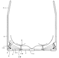
図1に示すように第1の実施の形態は、映像を表示する反射型のLCD(1R),LCD(1R)を照明するLED(2),LCD(1R)から発せられた映像光を屈曲して観察者の目(E)に導くとともに観察者の前方視界からの光を透過させうるように構成された光屈曲素子(3),前方視界からの光に対し光屈曲素子(3)が与える光学作用を打ち消すように補正する補正光学系(4),各構成要素を支持すると共に観察者の頭部に装着可能に構成された眼鏡フレーム(5,6)等、を備えた眼鏡型映像表示装置である。眼鏡フレーム(5)は鼻当て部(5a)を有しており、光屈曲素子(3)や補正光学系(4)等を支持している。また、眼鏡フレーム(6)は耳かけ部(6a)を有しており、LCD(1R)等を支持している。
【0011】
この実施の形態は眼鏡型の頭部装着表示装置であるため、装置全体がより軽量・小型になっている。観察者がこの映像表示装置を頭部に装着すると、目(E)の前方には光屈曲素子(3)が配されることになり、目(E)の側方にはLCD(1R)が配されることになる。LCD(1R)は像面(1b)に映像を表示し、その像面(1b)はLED(2)からの光で直接照明されるか、あるいは半透過反射面(1a)での反射により間接的に照明される。このようにLED(2)や半透過反射面(1a)から成る照明手段でLCD(1R)が照明されると、像面(1b)から映像光が射出し、その映像光は半透過反射面(1a)を透過して光屈曲素子(3)の入射面(3a)に斜入射する。なお、この入射面(3a)は観察者の目(E)への射出面と同一面であって、目(E)の視線(つまり、装置装着状態で観察者が正面を見ているときの視線)に対して略垂直になっている。
【0012】
LCD(1R)からの映像光は、入射面(3a)に対してP型偏光になるように偏光方向が設定されている。このように入射面(3a)に対するP型偏光を映像光として用いると、光屈曲素子(3)の入射面(3a)での表面反射を小さくすることができる。その結果、観察者の目(E)に有害なフレアー光が抑制されるとともに、省電力で明るい映像が得られる。
【0013】
入射面(3a)に斜入射した映像光は、入射面(3a)で屈折することになる。入射面(3a)で屈折した映像光のうち、光屈曲素子(3)のくさび部分(3W)又はその近傍を通過したものは、くさび部分(3W)の傾斜面に貼り付けられているホログラム(3R)に入射する。このホログラム(3R)は、回折光学面を構成する反射型の回折光学素子であり、映像を虚像として目(E)に導くために、非軸配置された凹面鏡として作用する。したがって、ホログラム(3R)に入射した映像光は、観察者の目(E)に向けて回折されるとともに、その回折によりコリメートされて入射面(3a)を射出する。入射面(3a)を射出した映像光は瞳(E)に入射し、観察者は映像を虚像として観察することになる。なお、光屈曲素子(3)を構成しているくさび部分(3W)等の光透過部分は、ホログラム(3R)よりも高い屈折率の材料から成っている。
【0014】
ホログラム(3R)から成る回折光学面は、LCD(1R)からの映像光の入射角が小さくなるように、入射面(3a)に対して傾斜しており、その入射角が更に小さくなるように、光屈曲素子(3)が入射面(3a)で映像光を屈折させる構成になっている。回折光学面に対する映像光の入射角を小さくすると、回折光学面に対する入射角と射出角とを等しくすること(正反射条件)ができるので、高い回折効率を達成することができ、回折光学面の光学設計も容易になる。また、LCD(1R)からの映像光が入射面(3a)に対して大きな入射角で斜入射する構成となっているため、光屈曲素子(3)とLCD(1R)との距離が観察者の視線方向に短くなる。したがって、眼鏡前部の薄型化を達成することができる。
【0015】
光屈曲素子(3)のくさび部分(3W)には、ホログラム(3R)を介して補正光学系(4)が貼り付けられている。つまり、光屈曲素子(3)と補正光学系(4)とは、ホログラム(3R)を挟んで貼り合わされた状態にあり、厚さ5mm以下の非常に薄い平板を成しているのである。前述したように、光屈曲素子(3)はLCD(1R)からの映像光を屈曲して観察者の目(E)に導く一方で、観察者の前方視界からの光を透過させうるように構成されている。したがって、前方視界からの光が光屈曲素子(3)のくさび部分(3W)を透過すると、くさび部分(3W)のパワーによって前方視界からの光が屈曲されることになる。なお、くさび部分(3W)を曲面で構成した場合には、その曲面のパワーによって前方視界が拡大又は縮小されることになる。このような光学作用を打ち消すように補正するのが補正光学系(4)である。補正光学系(4)が光屈曲素子(3)のパワーを相殺するため、観察者は通常(つまり本装置を装着していないとき)と同様に前方視界を観察することが可能である。
【0016】
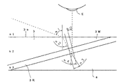
次に、光屈曲素子(3)のくさび部分(3W)とホログラム(3R)の光学作用を図5に基づいて説明する。LCD(1R)からの映像光(図5中、破線で示す。)は、空気中から入射面(3a)に大きな入射角α1で斜入射し、屈折角α2で屈折する。入射面(3a)は目(E)の視線に対して略垂直になっているので、目(E)の視線と映像光とのなす角度α1が入射面(3a)に対する入射角となるのである。入射面(3a)で屈折した映像光は、くさび部分(3W)を通過してホログラム(3R)に入射する。
【0017】
ホログラム(3R)は入射面(3a)に対して傾斜角α0だけ傾いているため、ホログラム(3R)に対する映像光の入射角は(α2−α0)となる。映像光はホログラム(3R)への入射時に屈折角α3で屈折され、ホログラム(3R)中に記録されているフリンジによって回折される。ここでは図を簡略化するために、ホログラム(3R)と補正光学系(4)との界面を回折光学面として、その回折光学面で映像光が回折するものとする。回折した映像光は、くさび部分(3W)に対する入射角α4,屈折角α0でホログラム(3R)から射出した後、入射面(3a)を略垂直に射出して観察者の瞳(E)に入射する。
【0018】
ここで、空気の屈折率をn1とし、くさび部分(3W)の屈折率をn2とし、ホログラム(3R)の屈折率をn3とすると、屈折の法則から以下の式▲1▼〜▲3▼が成り立つ。
n1・sinα1=n2・sinα2 …▲1▼
n2・sin(α2−α0)=n3・sinα3 …▲2▼
n3・sinα4=n2・sinα0 …▲3▼
【0019】
上記各式▲1▼〜▲3▼において、α0=14度,α1=70度,n1=1,n2=2,n3=1.5とすると、α3≒α4≒18.8度となる。つまり、反射型ホログラム(3R)による回折は、回折光学面に対する入射角と射出角とが等しい正反射に近い角度で行われることになる。したがって、M.G.MoharamとT.K.GaylordがJ.Opt.Soc.Am./Vol.71,No7/July 1981で示しているように、高い回折効率を達成することができる。
【0020】
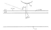
次に、上記第1の実施の形態(図5)との比較のために第1の比較例を挙げて、そのホログラムの光学作用を図6に基づいて説明する。図6に示す第1の比較例は、前述した特開平10−301055号公報で提案されているホログラム構成(眼鏡レンズ表面にホログラムを貼り付けた構成)に相当するものである。基板(11)上にはホログラム(11R)が貼り付けられており、目(E)の視線に対して略垂直にホログラム(11R)と基板(11)が配置されている。
【0021】
映像光(図6中、破線で示す。)は、空気中から入射面(11a)に大きな入射角α1で斜入射し、屈折角α5で屈折する。入射面(11a)は目(E)の視線に対して略垂直になっているので、目(E)の視線と映像光とのなす角度α1が入射面(11a)に対する入射角となるのである。ホログラム(11R)に入射した映像光は、ホログラム(11R)中に記録されているフリンジによって回折される。ここでは図を簡略化するために、ホログラム(11R)と基板(11)との界面を回折光学面として、その回折光学面で映像光が回折するものとする。回折した映像光は、入射面(11a)を略垂直に射出して観察者の瞳(E)に入射する。
【0022】
ここで、空気の屈折率をn1とし、ホログラム(11R)の屈折率をn3とすると、屈折の法則から以下の式▲4▼が成り立つ。
n1・sinα1=n3・sinα5 …▲4▼
【0023】
上式▲4▼において、α1=70度,n1=1,n3=1.5とすると、α5=38.8度となる。回折光学面からの射出角が0度であるので、反射型ホログラム(11R)による回折は、正反射角度から38.8度ずれた角度で行われることになる。したがって、M.G.MoharamとT.K.GaylordがJ.Opt.Soc.Am./Vol.71,No7/July 1981で示しているように、回折効率は悪くなってしまう。
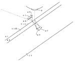
【0024】
さらに、前記第1の実施の形態(図5)との比較のために第2の比較例を挙げて、そのホログラムの光学作用を図7に基づいて説明する。図7に示す第2の比較例は、ホログラム(11R)で映像光を正反射方向に射出させるために、ホログラム(11R)及び基板(11)を第1の比較例の状態から傾斜角α9だけ傾けたものである。
【0025】
映像光(図7中、破線で示す。)は、空気中から入射面(11a)に入射角α6で斜入射し、屈折角α7で屈折する。入射面(11a)の法線が目(E)の視線に対して傾斜角α9だけ傾いているので、目(E)の視線と映像光とのなす角度α1と傾斜角α9との差(α1−α9)が入射面(11a)に対する入射角α6となるのである。ホログラム(11R)に入射した映像光は、ホログラム(11R)中に記録されているフリンジによって回折される。ここでは図を簡略化するために、ホログラム(11R)と基板(11)との界面を回折光学面として、その回折光学面で映像光が回折するものとする。回折した映像光は、入射面(11a)に対する入射角α8,屈折角α9でホログラム(11R)から射出して観察者の瞳(E)に入射する。
【0026】
ここで、空気の屈折率をn1とし、ホログラム(11R)の屈折率をn3とすると、屈折の法則から以下の式▲5▼,▲6▼が成り立つ。
n1・sinα6=n3・sinα7 …▲5▼
n3・sinα8=n1・sinα9 …▲6▼
【0027】
上記各式▲5▼,▲6▼において、α9=35度,α1=70度,n1=1,n3=1.5とすると(ただし、α6=α1−α9である。)、α7=α8=22.5度となる。つまり、反射型ホログラム(11R)による回折は、回折光学面に対する入射角と射出角とが等しい正反射に近い角度で行われることになる。したがって、M.G.MoharamとT.K.GaylordがJ.Opt.Soc.Am./Vol.71,No7/July 1981で示しているように、高い回折効率を達成することができる。しかし、このように基板(11)を35度(=α9)も傾斜させると、装置が目(E)の視線方向に大型化してしまうことになる。つまり、ホログラム(11R)が貼り付けられた眼鏡レンズを傾斜させることにより入射角を射出角に近づけたとしても、所定の大きさの視野角で観察瞳径とアイレリーフを確保しながら装置を小型化することは困難なのである。
【0028】
《第2の実施の形態(図2)》
図2に、第2の実施の形態の光学系部分を示す。眼鏡フレーム構成は、前述した第1の実施の形態と同様である。この実施の形態では、映像を表示する表示手段として透過型のLCD(1T)が用いられており、LCD(1T)を照明する照明手段としてバックライト(2B)が用いられている。また、光屈曲素子(3)と補正光学系(4)の各面(3a,3b;4a,4b)の曲率が、観察者の目(E)に対して視力を矯正するように設定されている。つまり、光屈曲素子(3)と補正光学系(4)とは、ホログラム(3R)を挟んで貼り合わされた状態にあり、面(3a)と面(4a)とで滑らかな曲面が形成され、かつ、面(3b)と面(4b)とで滑らかな曲面が形成されたレンズ形状を成しているのである。そのレンズ形状の一部を成す補正光学系(4)は、前方視界からの光に対し光屈曲素子(3)がくさび部分(3W)でのみ与える光学作用を打ち消すように補正するため、くさび部分(3W)で前方視界からの光が屈曲されたり、前方視界が縮小されたりすることはない。
【0029】
《第3の実施の形態(図3)》
図3に、第3の実施の形態の光学系部分を示す。眼鏡フレーム構成は、前述した第1の実施の形態と同様である。この実施の形態では湾曲したホログラム(3R)が用いられており、そのホログラム(3R)は、折り返される光軸によって形成される平面の法線方向に平行な軸(つまり紙面に垂直な軸)を中心に湾曲している。このように湾曲したホログラム(3R)を用いることにより、軸上光及び軸外光に対する回折効率を上げることができる。また、ホログラム(3R)が貼り付けられているくさび部分(3W)の湾曲が前方視界からの光に与える光学作用を、補正光学系(4)が打ち消すように補正するため、くさび部分(3W)で前方視界からの光が屈曲されたり、前方視界が拡大されたりすることはない。なお、第3の実施の形態では回折光学面が平面状でないため、この点で第3の実施の形態は本発明の参考のための一形態にすぎず、本発明には属さないものである。
【0030】
《第4の実施の形態(図4)》
図4に、第4の実施の形態を示す。この実施の形態の特徴は、透過型のホログラム(3T)を用いた点にある。回折光学面を透過型のホログラム(3T)で構成するのに合わせて、反射型LCD(1R)を眼鏡フレーム(5)の前側上方に配置する等の変更を加えたほかは、前記第1の実施の形態とほぼ同様の構成になっている。LCD(1R)から入射面(3a)に斜入射して屈折した映像光のうち、光屈曲素子(3)のくさび部分(3W)又はその近傍を通過したものは、くさび部分(3W)の傾斜面に貼り付けられているホログラム(3T)に入射する。このホログラム(3T)は、映像を虚像として目(E)に導くために、非軸配置された凸レンズとして作用する。したがって、ホログラム(3T)に入射した映像光は、観察者の目(E)に向けて回折されるとともに、その回折によりコリメートされて補正光学系(4)を透過する。補正光学系(4)の射出面(4c)を射出した映像光は瞳(E)に入射し、観察者は映像を虚像として観察することになる。
【0031】
【発明の効果】
以上説明したように本発明によれば、映像光の入射角が小さくなるように回折光学面が入射面に対して傾斜した構成になっているので、小型(特に薄型・軽量)でありながら高画質の映像表示が可能な映像表示装置を実現することができる。しかも比較的簡単な構成で実現可能であるため、装置の低コスト化が可能である。
【図面の簡単な説明】
【図1】第1の実施の形態を示す平面図。
【図2】第2の実施の形態の要部光学構成を示す平面図。
【図3】第3の実施の形態の要部光学構成を示す平面図。
【図4】第4の実施の形態の要部光学構成を示す縦断面図。
【図5】第1の実施の形態における光屈曲素子のくさび部分とホログラムの光学作用を示す光学構成図。
【図6】第1の比較例におけるホログラムの光学作用を示す光学構成図。
【図7】第2の比較例におけるホログラムの光学作用を示す光学構成図。
【符号の説明】
1R …反射型のLCD(表示手段)
1T …透過型のLCD(表示手段)
1a …半透過反射面
1b …像面
2 …LED
2B …バックライト
3 …光屈曲素子
3a …入射面
3R …反射型のホログラム(回折光学面)
3T …透過型のホログラム(回折光学面)
3W …くさび部分
4 …補正光学系
E …目(瞳)[0001]
BACKGROUND OF THE INVENTION
The present invention relates to a video display device, and is suitable as, for example, an HMD (head mounted display) that projects a two-dimensional video displayed on an LCD (liquid crystal display) to an observer's eyes and observes a magnified virtual image thereof. The present invention relates to an image display device.
[0002]
[Prior art]
Japanese Patent Application Laid-Open No. 10-301055 proposes a light-weight and small-sized image display device using a hologram. In this video display device, a reflective hologram having a lens function is provided on the lens surface of the spectacles, and a display unit for emitting video light is provided on the handle of the spectacles. The hologram performs enlarged projection of the image by reflecting the image light from the display unit toward the eyes of the observer. Although the incident angle of the image light with respect to the hologram is larger than the exit angle, the incident angle and the exit angle do not necessarily have to be equal in the reflection by the hologram. This is advantageous in reducing the size of the entire apparatus.
[0003]
[Problems to be solved by the invention]
However, if the incident angle of the image light with respect to the hologram is made larger than the exit angle as described above, the diffraction efficiency becomes worse (see J.Opt.Soc.Am./Vol.71,No7/July 1981 (MGMoharam and TKGaylord) }. When the diffraction efficiency is deteriorated, flare is generated or the brightness of the image is lowered, so that the image quality of the display image is lowered.
[0004]
The present invention has been made in view of such a situation, and an object of the present invention is to provide a video display device capable of displaying high-quality video while being small.
[0005]
[Means for Solving the Problems]
In order to achieve the above object, a video display device according to a first aspect of the present invention is a display means for displaying a video, an incident surface that is arranged in front of an observer's eye and on which video light is obliquely incident, and a virtual image of the video. And having a planar diffractive optical surface that is inclined with respect to the incident surface so that the incident angle of the image light is small, and an exit surface that is substantially perpendicular to the line of sight. The diffractive optical surface is made of a material having a high refractive index, diffracts the image light toward the observer's eyes by the diffractive optical surface, and has an optical power for collimating the image light by the diffraction. And a light bending element that bends the image light and reduces the angle of incidence on the diffractive optical surface.
[0006]
According to a second aspect of the present invention, there is provided a video display device according to the first aspect, wherein the light bending element is configured to transmit light from a viewer's front field of view, and light from the front field of view. On the other hand, a correction optical system for correcting so as to cancel the optical action given by the light bending element is provided.
[0007]
According to a third aspect of the present invention, in the configuration of the first aspect, the polarization direction is set so that the image light from the display means is P-type polarized light with respect to the incident surface. And
[0008]
According to a fourth aspect of the present invention, there is provided the video display device according to the first, second or third aspect of the invention, further configured to support the display means and the light bending element and be attachable to the observer's head. A spectacle frame is provided.
[0009]
DETAILED DESCRIPTION OF THE INVENTION
Hereinafter, an image display apparatus embodying the present invention will be described with reference to the drawings. Note that the same or corresponding parts in the embodiment and the like are denoted by the same reference numerals, and redundant description is omitted as appropriate.
[0010]
<< First Embodiment (FIG. 1) >>
As shown in FIG. 1, the first embodiment bends image light emitted from a reflective LCD (1R) for displaying an image, an LED (2) for illuminating the LCD (1R), and the LCD (1R). The light bending element (3) is configured to guide the observer's eyes (E) and transmit light from the observer's front field of view. Eyeglass-type image with correction optical system (4) that corrects the applied optical action to cancel, and eyeglass frames (5,6) that support each component and can be worn on the observer's head It is a display device. The spectacle frame (5) has a nose pad portion (5a), and supports the light bending element (3), the correction optical system (4), and the like. The spectacle frame (6) has an ear hook (6a), and supports the LCD (1R) and the like.
[0011]
Since this embodiment is a glasses-type head-mounted display device, the entire device is lighter and smaller. When the observer wears this image display device on the head, the light bending element (3) is arranged in front of the eye (E), and the LCD (1R) is located on the side of the eye (E). Will be arranged. The LCD (1R) displays an image on the image plane (1b), and the image plane (1b) is directly illuminated by the light from the LED (2) or indirectly by reflection on the transflective surface (1a). Illuminated. Thus, when the LCD (1R) is illuminated by the illumination means comprising the LED (2) and the transflective surface (1a), image light is emitted from the image surface (1b), and the image light is transmitted through the transflective surface. The light passes through (1a) and is obliquely incident on the incident surface (3a) of the light bending element (3). Note that this entrance surface (3a) is the same surface as the exit surface to the observer's eye (E), and the line of sight of the eye (E) (i.e., when the observer is looking in front with the device attached) It is substantially perpendicular to the line of sight.
[0012]
The polarization direction of the image light from the LCD (1R) is set so as to be P-type polarized light with respect to the incident surface (3a). When the P-type polarized light with respect to the incident surface (3a) is used as image light in this way, the surface reflection at the incident surface (3a) of the light bending element (3) can be reduced. As a result, flare light harmful to the eyes (E) of the observer is suppressed, and a bright image can be obtained with power saving.
[0013]
The image light obliquely incident on the incident surface (3a) is refracted by the incident surface (3a). Of the image light refracted at the incident surface (3a), the one that has passed through the wedge part (3W) of the light bending element (3) or the vicinity thereof is a hologram attached to the inclined surface of the wedge part (3W) ( Incident on 3R). This hologram (3R) is a reflection type diffractive optical element constituting a diffractive optical surface, and acts as a non-axially arranged concave mirror in order to guide an image as a virtual image to the eye (E). Therefore, the image light incident on the hologram (3R) is diffracted toward the observer's eyes (E), and collimated by the diffraction, and exits the incident surface (3a). The image light emitted from the incident surface (3a) enters the pupil (E), and the observer observes the image as a virtual image. The light transmitting part such as the wedge part (3W) constituting the light bending element (3) is made of a material having a higher refractive index than that of the hologram (3R).
[0014]
The diffractive optical surface composed of the hologram (3R) is inclined with respect to the incident surface (3a) so that the incident angle of the image light from the LCD (1R) is small, so that the incident angle is further reduced. The light bending element (3) is configured to refract video light at the incident surface (3a). If the incident angle of the image light with respect to the diffractive optical surface is reduced, the incident angle and the exit angle with respect to the diffractive optical surface can be made equal (regular reflection condition), so that high diffraction efficiency can be achieved, and Optical design is also facilitated. In addition, since the image light from the LCD (1R) is obliquely incident on the incident surface (3a) at a large incident angle, the distance between the light bending element (3) and the LCD (1R) is determined by the observer. It becomes shorter in the line-of-sight direction. Therefore, it is possible to reduce the thickness of the front part of the glasses.
[0015]
The correction optical system (4) is attached to the wedge portion (3W) of the light bending element (3) via the hologram (3R). That is, the light bending element (3) and the correction optical system (4) are in a state of being bonded with the hologram (3R) interposed therebetween, and form a very thin flat plate having a thickness of 5 mm or less. As described above, the light bending element (3) bends the image light from the LCD (1R) and guides it to the viewer's eyes (E), while allowing the light from the viewer's front field to pass therethrough. It is configured. Therefore, when the light from the front view passes through the wedge portion (3W) of the light bending element (3), the light from the front view is bent by the power of the wedge portion (3W). When the wedge portion (3W) is formed of a curved surface, the front field of view is enlarged or reduced by the power of the curved surface. The correction optical system (4) corrects such an optical action so as to cancel. Since the correction optical system (4) cancels the power of the light bending element (3), the observer can observe the front field of view as usual (that is, when the apparatus is not worn).
[0016]
Next, the optical action of the wedge portion (3W) of the light bending element (3) and the hologram (3R) will be described with reference to FIG. Video light from the LCD (1R) (indicated by a broken line in FIG. 5) is obliquely incident on the incident surface (3a) from the air at a large incident angle α1, and is refracted at a refraction angle α2. Since the incident surface (3a) is substantially perpendicular to the line of sight of the eye (E), the angle α1 between the line of sight of the eye (E) and the image light becomes the incident angle with respect to the incident surface (3a). . The image light refracted on the incident surface (3a) passes through the wedge portion (3W) and enters the hologram (3R).
[0017]
Since the hologram (3R) is inclined with respect to the incident surface (3a) by the inclination angle α0, the incident angle of the image light with respect to the hologram (3R) is (α2−α0). The image light is refracted at a refraction angle α3 when incident on the hologram (3R) and is diffracted by the fringe recorded in the hologram (3R). Here, to simplify the drawing, it is assumed that the interface between the hologram (3R) and the correction optical system (4) is a diffractive optical surface, and the image light is diffracted by the diffractive optical surface. The diffracted image light exits from the hologram (3R) at an incident angle α4 and a refraction angle α0 with respect to the wedge part (3W), and then exits the incident surface (3a) substantially perpendicularly and enters the observer's pupil (E). To do.
[0018]
Here, when the refractive index of air is n1, the refractive index of the wedge portion (3W) is n2, and the refractive index of the hologram (3R) is n3, the following formulas (1) to (3) are obtained from the law of refraction. It holds.
n1 · sinα1 = n2 · sinα2 (1)
n2 · sin (α2−α0) = n3 · sinα3 (2)
n3 · sinα4 = n2 · sinα0 (3)
[0019]
In the above equations (1) to (3), when α0 = 14 degrees, α1 = 70 degrees, n1 = 1, n2 = 2, and n3 = 1.5, α3≈α4≈18.8 degrees. That is, diffraction by the reflection type hologram (3R) is performed at an angle close to regular reflection where the incident angle and the exit angle with respect to the diffractive optical surface are equal. Therefore, as shown in J.Opt.Soc.Am./Vol.71,No7/July 1981 by MGMoharam and TKGaylord, high diffraction efficiency can be achieved.
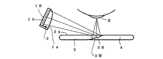
[0020]
Next, for comparison with the first embodiment (FIG. 5), a first comparative example will be given and the optical action of the hologram will be described with reference to FIG. The first comparative example shown in FIG. 6 corresponds to the hologram configuration (configuration in which a hologram is pasted on the spectacle lens surface) proposed in Japanese Patent Laid-Open No. 10-301055 described above. A hologram (11R) is pasted on the substrate (11), and the hologram (11R) and the substrate (11) are arranged substantially perpendicular to the line of sight of the eye (E).
[0021]
Video light (indicated by a broken line in FIG. 6) is obliquely incident on the incident surface (11a) from the air at a large incident angle α1, and is refracted at a refraction angle α5. Since the incident surface (11a) is substantially perpendicular to the line of sight of the eye (E), the angle α1 between the line of sight of the eye (E) and the image light becomes the incident angle with respect to the incident surface (11a). . The image light incident on the hologram (11R) is diffracted by the fringe recorded in the hologram (11R). Here, to simplify the drawing, it is assumed that the interface between the hologram (11R) and the substrate (11) is a diffractive optical surface, and the image light is diffracted by the diffractive optical surface. The diffracted image light exits the incident surface (11a) substantially perpendicularly and enters the observer's pupil (E).
[0022]
Here, assuming that the refractive index of air is n1 and the refractive index of the hologram (11R) is n3, the following formula (4) is established from the law of refraction.
n1 · sinα1 = n3 · sinα5 (4)
[0023]
In the above formula (4), if α1 = 70 degrees, n1 = 1, and n3 = 1.5, then α5 = 38.8 degrees. Since the exit angle from the diffractive optical surface is 0 degree, the diffraction by the reflection hologram (11R) is performed at an angle shifted by 38.8 degrees from the regular reflection angle. Therefore, as shown in J.Opt.Soc.Am./Vol.71,No7/July 1981 by MGMoharam and TKGaylord, the diffraction efficiency is deteriorated.
[0024]
Further, for comparison with the first embodiment (FIG. 5), a second comparative example will be given and the optical action of the hologram will be described with reference to FIG. In the second comparative example shown in FIG. 7, in order to emit image light in the regular reflection direction with the hologram (11R), the hologram (11R) and the substrate (11) are tilted from the state of the first comparative example by an inclination angle α9. It is tilted.
[0025]
Video light (indicated by a broken line in FIG. 7) is obliquely incident from the air on the incident surface (11a) at an incident angle α6 and is refracted at a refraction angle α7. Since the normal of the incident surface (11a) is inclined by an inclination angle α9 with respect to the line of sight of the eye (E), the difference between the angle α1 formed by the line of sight of the eye (E) and the image light and the inclination angle α9 (α1 −α9) becomes the incident angle α6 with respect to the incident surface (11a). The image light incident on the hologram (11R) is diffracted by the fringe recorded in the hologram (11R). Here, to simplify the drawing, it is assumed that the interface between the hologram (11R) and the substrate (11) is a diffractive optical surface, and the image light is diffracted by the diffractive optical surface. The diffracted image light exits from the hologram (11R) at an incident angle α8 and a refraction angle α9 with respect to the incident surface (11a) and enters the observer's pupil (E).
[0026]
Here, assuming that the refractive index of air is n1 and the refractive index of the hologram (11R) is n3, the following formulas (5) and (6) are established from the law of refraction.
n1 · sinα6 = n3 · sinα7 (5)
n3 · sinα8 = n1 · sinα9… ▲ 6 ▼
[0027]
In the above formulas (5) and (6), if α9 = 35 degrees, α1 = 70 degrees, n1 = 1, and n3 = 1.5 (where α6 = α1-α9), α7 = α8 = 22.5 degrees. That is, diffraction by the reflection hologram (11R) is performed at an angle close to regular reflection where the incident angle and the exit angle with respect to the diffractive optical surface are equal. Therefore, as shown in J.Opt.Soc.Am./Vol.71,No7/July 1981 by MGMoharam and TKGaylord, high diffraction efficiency can be achieved. However, if the substrate (11) is tilted by 35 degrees (= α9) in this way, the apparatus becomes larger in the direction of the line of sight of the eye (E). In other words, even if the incident angle is made closer to the exit angle by tilting the spectacle lens with the hologram (11R) attached, the device can be made smaller while ensuring the observation pupil diameter and eye relief at a predetermined viewing angle. It is difficult to make it.
[0028]
<< Second Embodiment (FIG. 2) >>
FIG. 2 shows an optical system portion of the second embodiment. The spectacle frame configuration is the same as that of the first embodiment described above. In this embodiment, a transmissive LCD (1T) is used as display means for displaying an image, and a backlight (2B) is used as illumination means for illuminating the LCD (1T). Further, the curvature of each surface (3a, 3b; 4a, 4b) of the light bending element (3) and the correction optical system (4) is set so as to correct the visual acuity with respect to the observer's eyes (E). Yes. That is, the light bending element (3) and the correction optical system (4) are in a state of being bonded with the hologram (3R) interposed therebetween, and a smooth curved surface is formed by the surface (3a) and the surface (4a). In addition, the surface (3b) and the surface (4b) form a lens shape in which a smooth curved surface is formed. The correction optical system (4) that forms part of the lens shape corrects the optical bending element (3) so as to cancel out the optical action that the light bending element (3) gives only at the wedge part (3W) to the light from the front field of view. At (3W), the light from the front field of view is not bent or the front field of view is not reduced.
[0029]
<< Third Embodiment (FIG. 3) >>
FIG. 3 shows an optical system portion of the third embodiment. The spectacle frame configuration is the same as that of the first embodiment described above. In this embodiment, a curved hologram (3R) is used, and the hologram (3R) has an axis parallel to the normal direction of the plane formed by the folded optical axis (that is, an axis perpendicular to the paper surface). Curved to the center. By using the hologram (3R) curved in this way, the diffraction efficiency for on-axis light and off-axis light can be increased. Also, in order to correct the optical action that the curvature of the wedge part (3W) to which the hologram (3R) is attached has on the light from the front field of view, the correction optical system (4) cancels out the wedge part (3W). Thus, the light from the front view is not bent or the front view is not enlarged. In the third embodiment, since the diffractive optical surface is not planar, the third embodiment is merely a form for reference of the present invention and does not belong to the present invention. .
[0030]
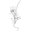
<< Fourth Embodiment (FIG. 4) >>
FIG. 4 shows a fourth embodiment. The feature of this embodiment is that a transmission hologram (3T) is used. According to the first embodiment, except that the reflective LCD (1R) is arranged on the upper front side of the spectacle frame (5) in accordance with the construction of the diffractive optical surface with the transmission hologram (3T). The configuration is almost the same as in the embodiment. Of the image light obliquely incident on the incident surface (3a) from the LCD (1R) and refracted, the image light that has passed through the wedge part (3W) of the light bending element (3) or its vicinity is inclined by the wedge part (3W). Incident on the hologram (3T) affixed to the surface. This hologram (3T) acts as a non-axially arranged convex lens to guide the image as a virtual image to the eye (E). Accordingly, the image light incident on the hologram (3T) is diffracted toward the observer's eyes (E), collimated by the diffraction, and transmitted through the correction optical system (4). The image light emitted from the exit surface (4c) of the correction optical system (4) enters the pupil (E), and the observer observes the image as a virtual image.
[0031]
【The invention's effect】
As described above, according to the present invention, the diffractive optical surface is inclined with respect to the incident surface so as to reduce the incident angle of the image light. An image display device capable of displaying an image with high image quality can be realized. In addition, since it can be realized with a relatively simple configuration, the cost of the apparatus can be reduced.
[Brief description of the drawings]
FIG. 1 is a plan view showing a first embodiment.
FIG. 2 is a plan view showing an optical configuration of a main part of a second embodiment.
FIG. 3 is a plan view showing an optical configuration of a main part of a third embodiment.
FIG. 4 is a longitudinal sectional view showing an essential optical configuration of a fourth embodiment.
FIG. 5 is an optical configuration diagram showing an optical action of a wedge portion of a light bending element and a hologram in the first embodiment.
FIG. 6 is an optical configuration diagram showing an optical action of a hologram in the first comparative example.
FIG. 7 is an optical configuration diagram showing an optical action of a hologram in a second comparative example.
[Explanation of symbols]
1R: Reflective LCD (display means)
1T ... Transmission type LCD (display means)
1a ... Transflective surface
1b Image plane
2 ... LED
2B… Backlight
3 ... Light bending element
3a ... Incident surface
3R: Reflective hologram (diffractive optical surface)
3T ... Transmission hologram (diffractive optical surface)
3W… wedge part
4… correction optics
E ... eyes (eyes)
Claims (4)
観察者の目の前方に配され、映像光が斜入射する入射面と、前記映像を虚像として目に導き、かつ、映像光の入射角が小さくなるように前記入射面に対して傾斜した平面状の回折光学面と、視線に対して略垂直な射出面と、を有し、空気より屈折率の高い材料から成り、前記回折光学面で映像光を観察者の目に向けて回折し、その回折により映像光をコリメートする光学的パワーを前記回折光学面に有し、前記表示手段からの映像光を屈曲し、前記回折光学面への入射角を小さくする光屈曲素子と、
を備えたことを特徴とする映像表示装置。Display means for displaying video;
Disposed in front of the viewer's eye, the entrance surface image light is obliquely incident, it guides the eyes of the image as a virtual image, and inclined with respect to the incident surface such that the incident angle of the image light decreases plane A diffractive optical surface and an exit surface substantially perpendicular to the line of sight, made of a material having a higher refractive index than air, and diffracting image light toward the observer's eyes with the diffractive optical surface, An optical power for collimating image light by the diffraction on the diffractive optical surface, bending the image light from the display means, and a light bending element for reducing the incident angle to the diffractive optical surface;
A video display device comprising:
Priority Applications (1)
| Application Number | Priority Date | Filing Date | Title |
|---|---|---|---|
| JP24439099A JP4395673B2 (en) | 1999-08-31 | 1999-08-31 | Video display device |
Applications Claiming Priority (1)
| Application Number | Priority Date | Filing Date | Title |
|---|---|---|---|
| JP24439099A JP4395673B2 (en) | 1999-08-31 | 1999-08-31 | Video display device |
Publications (2)
| Publication Number | Publication Date |
|---|---|
| JP2001066544A JP2001066544A (en) | 2001-03-16 |
| JP4395673B2 true JP4395673B2 (en) | 2010-01-13 |
Family
ID=17117970
Family Applications (1)
| Application Number | Title | Priority Date | Filing Date |
|---|---|---|---|
| JP24439099A Expired - Fee Related JP4395673B2 (en) | 1999-08-31 | 1999-08-31 | Video display device |
Country Status (1)
| Country | Link |
|---|---|
| JP (1) | JP4395673B2 (en) |
Families Citing this family (6)
| Publication number | Priority date | Publication date | Assignee | Title |
|---|---|---|---|---|
| JP4543747B2 (en) * | 2004-05-20 | 2010-09-15 | ソニー株式会社 | Image display device |
| JP5389493B2 (en) | 2009-03-25 | 2014-01-15 | オリンパス株式会社 | Glasses-mounted image display device |
| CN110095869B (en) * | 2013-12-05 | 2021-09-14 | 索尼公司 | Display device |
| US9841598B2 (en) * | 2013-12-31 | 2017-12-12 | 3M Innovative Properties Company | Lens with embedded multilayer optical film for near-eye display systems |
| JP6812649B2 (en) * | 2016-03-24 | 2021-01-13 | セイコーエプソン株式会社 | Image display device |
| KR101894555B1 (en) * | 2016-09-07 | 2018-10-04 | 주식회사 레티널 | Reflecting lens module |
Family Cites Families (6)
| Publication number | Priority date | Publication date | Assignee | Title |
|---|---|---|---|---|
| EP0365406B1 (en) * | 1988-10-21 | 1993-09-29 | Thomson-Csf | Optical collimating system for a helmet visual |
| JP2959318B2 (en) * | 1993-03-24 | 1999-10-06 | 日産自動車株式会社 | Head-up type vehicle display |
| JPH09101478A (en) * | 1995-08-03 | 1997-04-15 | Denso Corp | Head-up display device |
| US5886822A (en) * | 1996-10-08 | 1999-03-23 | The Microoptical Corporation | Image combining system for eyeglasses and face masks |
| JPH10307263A (en) * | 1997-05-07 | 1998-11-17 | Olympus Optical Co Ltd | Prism optical element and image observation device |
| WO2000079327A1 (en) * | 1999-06-21 | 2000-12-28 | The Microoptical Corporation | Eyeglass display lens system employing off-axis optical design |
-
1999
- 1999-08-31 JP JP24439099A patent/JP4395673B2/en not_active Expired - Fee Related
Also Published As
| Publication number | Publication date |
|---|---|
| JP2001066544A (en) | 2001-03-16 |
Similar Documents
| Publication | Publication Date | Title |
|---|---|---|
| JP6994940B2 (en) | Head-mounted imaging device using optical coupling | |
| US8310764B2 (en) | Image display device and head mount display | |
| JP2005084522A (en) | Combiner optics | |
| JPWO2010061835A1 (en) | Video display device and head mounted display | |
| CN104698588A (en) | Virtual image display apparatus | |
| WO2010032700A1 (en) | Video image display device and head mount display | |
| JP6848310B2 (en) | Virtual image display device | |
| US10634915B2 (en) | Image display device | |
| CN109073896B (en) | Spectacle lenses for imaging optical units and data goggles | |
| US7688399B2 (en) | Image display apparatus | |
| CN104678555A (en) | Tooth-shaped embedding planar waveguide optical device for diopter correction | |
| JP2004021078A (en) | Combiner optical system and information display device | |
| JP2017058400A (en) | Image display device | |
| US11067804B2 (en) | Virtual image display device | |
| US20250155714A1 (en) | Optical device for augmented reality using polarizing optical element | |
| JP7027748B2 (en) | Virtual image display device | |
| JP4395673B2 (en) | Video display device | |
| US12025804B2 (en) | Virtual image display device and optical unit | |
| JP2004029544A (en) | Hologram combiner optical system and information display device | |
| JP4985247B2 (en) | Head mounted display | |
| JP4797531B2 (en) | Video display device | |
| US20190196194A1 (en) | Head-mounted display | |
| US20230011039A1 (en) | Display device | |
| JP2018066799A (en) | Image display device and optical see-through display | |
| US20240219722A1 (en) | Virtual image display device and optical unit |
Legal Events
| Date | Code | Title | Description |
|---|---|---|---|
| A711 | Notification of change in applicant |
Free format text: JAPANESE INTERMEDIATE CODE: A712 Effective date: 20050613 |
|
| A621 | Written request for application examination |
Free format text: JAPANESE INTERMEDIATE CODE: A621 Effective date: 20060424 |
|
| A977 | Report on retrieval |
Free format text: JAPANESE INTERMEDIATE CODE: A971007 Effective date: 20081202 |
|
| A131 | Notification of reasons for refusal |
Free format text: JAPANESE INTERMEDIATE CODE: A131 Effective date: 20081216 |
|
| A521 | Written amendment |
Free format text: JAPANESE INTERMEDIATE CODE: A523 Effective date: 20090206 |
|
| A02 | Decision of refusal |
Free format text: JAPANESE INTERMEDIATE CODE: A02 Effective date: 20090526 |
|
| A521 | Written amendment |
Free format text: JAPANESE INTERMEDIATE CODE: A523 Effective date: 20090807 |
|
| A911 | Transfer of reconsideration by examiner before appeal (zenchi) |
Free format text: JAPANESE INTERMEDIATE CODE: A911 Effective date: 20090901 |
|
| TRDD | Decision of grant or rejection written | ||
| A01 | Written decision to grant a patent or to grant a registration (utility model) |
Free format text: JAPANESE INTERMEDIATE CODE: A01 Effective date: 20090924 |
|
| A01 | Written decision to grant a patent or to grant a registration (utility model) |
Free format text: JAPANESE INTERMEDIATE CODE: A01 |
|
| A61 | First payment of annual fees (during grant procedure) |
Free format text: JAPANESE INTERMEDIATE CODE: A61 Effective date: 20091007 |
|
| FPAY | Renewal fee payment (event date is renewal date of database) |
Free format text: PAYMENT UNTIL: 20121030 Year of fee payment: 3 |
|
| R150 | Certificate of patent or registration of utility model |
Free format text: JAPANESE INTERMEDIATE CODE: R150 |
|
| FPAY | Renewal fee payment (event date is renewal date of database) |
Free format text: PAYMENT UNTIL: 20121030 Year of fee payment: 3 |
|
| FPAY | Renewal fee payment (event date is renewal date of database) |
Free format text: PAYMENT UNTIL: 20131030 Year of fee payment: 4 |
|
| S531 | Written request for registration of change of domicile |
Free format text: JAPANESE INTERMEDIATE CODE: R313531 |
|
| S533 | Written request for registration of change of name |
Free format text: JAPANESE INTERMEDIATE CODE: R313533 |
|
| R350 | Written notification of registration of transfer |
Free format text: JAPANESE INTERMEDIATE CODE: R350 |
|
| LAPS | Cancellation because of no payment of annual fees |