JP4395139B2 - Game machine - Google Patents
Game machine Download PDFInfo
- Publication number
- JP4395139B2 JP4395139B2 JP2006053932A JP2006053932A JP4395139B2 JP 4395139 B2 JP4395139 B2 JP 4395139B2 JP 2006053932 A JP2006053932 A JP 2006053932A JP 2006053932 A JP2006053932 A JP 2006053932A JP 4395139 B2 JP4395139 B2 JP 4395139B2
- Authority
- JP
- Japan
- Prior art keywords
- base
- case
- gaming machine
- case cover
- fixing
- Prior art date
- Legal status (The legal status is an assumption and is not a legal conclusion. Google has not performed a legal analysis and makes no representation as to the accuracy of the status listed.)
- Expired - Fee Related
Links
Images


Landscapes
- Pinball Game Machines (AREA)
Description
この発明は、パチンコ機やスロットマシンなどの遊技機に用いられる遊技機用の制御基盤を収納するための遊技機用の基盤ケースに関するものである。 The present invention relates to a base case for a gaming machine for storing a control base for a gaming machine used in a gaming machine such as a pachinko machine or a slot machine.
従来、この種の遊技機としては、基盤ケースに収納された制御基盤に取り付けられた遊技を制御するためのプログラムを記憶した正規のROMを、出玉率などに関するプログラムを変更した不正に改造されているが外見上は判別不能な改造ROMに交換する不正行為を有効に防止する必要があった。
また、検査などの都合でケースカバーを開放することできるように形成されている必要もあった。
In addition, it is necessary to form the case cover so that it can be opened for inspection or the like.
しかし、上記した従来の遊技機用の基盤ケースでは、ケースカバーを開放するためには、その都度、破断部を破断しなければならず、検査などの都合で、ケースカバーを開放し再び基盤ケースに固定する作業を度重ねると、予め形成されていた取付部の破断部を全て破断してしまい、全ての取付部を使い切ってしまうことがある。この場合、基盤ケース側の取付部は、新たな基盤ケースを用いることで足りるが、遊技機側には、破断した取付部が固定された状態で残ってしまい、再び使用することができないといった問題点があった。 However, in the above-mentioned conventional base case for gaming machines, in order to open the case cover, the broken part must be broken each time, and the case cover is opened again for convenience of inspection or the like. If the work of fixing to each other is repeated, all the rupture portions of the attachment portion formed in advance may be broken, and all the attachment portions may be used up. In this case, it is sufficient to use a new base case for the mounting part on the base case side, but on the gaming machine side, the broken mounting part remains fixed and cannot be used again. There was a point.
そこで、請求項1記載の遊技機は、取付部の第一の破断部を破断する以外に、基盤ケースを遊技機から離脱することのできないようにして、基盤ケースを離脱した痕跡が必ず残るようにする一方、固定部材を新たに交換することを可能とすることにより、基盤ケースの開放が度重なる場合でも継続的に使用することのできる遊技機を提供しようとするものである。 Therefore, in the gaming machine according to claim 1, the base case cannot be detached from the gaming machine except for breaking the first fracture portion of the mounting portion, so that the trace of the base case is always left. On the other hand, it is an object of the present invention to provide a gaming machine that can be used continuously even when the opening of the base case is repeated by making it possible to newly replace the fixing member.
さらに、請求項1記載の遊技機は、ベースごと遊技機から取り外すことのできない遊技機用を提供しようとするものである。
加えて、請求項1記載の遊技機は、遊技機への固定が簡単迅速な遊技機を提供しようとするものである。
Furthermore, the gaming machine according to claim 1 is intended to provide a gaming machine that cannot be removed from the gaming machine together with the base.
In addition, the gaming machine according to claim 1 is intended to provide a gaming machine that can be easily and quickly fixed to the gaming machine.
(特徴点)
本発明は、上記した目的を達成するためのものであり、以下にその内容を図面に示した発明の実施の形態の一例を用いて説明する。
なお、カッコ内の符号は、発明の実施の形態において用いた符号を示すが、本発明の技術的範囲を限定するものではない。
(請求項1)
請求項1記載の遊技機は、遊技機の制御を行うための制御基盤を収納し遊技機に取り付けられる基盤ケース(10)と、前記基盤ケース(10)を遊技機に固定するためのベース(20)と、を備えた遊技機であって、前記基盤ケース(10)は、遊技機に固定されるケース本体(30)と、前記ケース本体(30)を覆うように、該ケース本体(30)に固定され、固定部材(50)を介して遊技機に対して固定されるケースカバー(40)とを備え、前記ケースカバー(40)には、ケースカバー(40)から張り出した第一の破断部(101)を介して、ケースカバー(40)を前記ベース(20)に取り付けるための複数の取付部(100)を有し、前記固定部材(50)は、基盤ケース(10)の遊技機への固定前の状態で前記ベース(20)に対してスライド方向からの着脱を可能に形成されるとともに、前記固定部材(50)には、前記複数の取付部(100)に対応して、各取付部(100)に各々固定可能な複数の固定部(70)を有し、前記取付部(100)の少なくとも一つは、該取付部(100)に対応する前記固定部(70)とによって前記ベース(20)を介して遊技機に取り付けられ、基盤ケース(10)を遊技機に取り付けるに際し、取付に用いていない取付部(100)を次回以降の固定に使用できるようにし、前記ケースカバー(40)には、その一側に、取付部(100)が形成され、この取付部(100)が形成されていない他側に、前記ベース(20)に形成された係合孔(23)にはまり込むために、外方に突出した係合突起(41)が形成され、前記ベース(20)には、前記ケースカバーの反係合突起(41)側に形成され、前記ケースカバー(40)を前記ベース(20)に取り付ける際には、反ケースカバー(40)方向へ弾性変形するとともに、前記ケースカバー(40)を前記ベースに取り付けた状態では、前記弾性変形を復元することにより、前記ケースカバー(40)を前記ベース(20)へ押しつけて、前記ケースカバー(40)が前記ベース(20)から離脱するのを阻止する係止突起(22)と、を備えたことを特徴とする。
(Feature point)
The present invention is for achieving the above-described object, and the contents thereof will be described below by using an example of the embodiment of the invention shown in the drawings.
In addition, although the code | symbol in parenthesis shows the code | symbol used in embodiment of invention, it does not limit the technical scope of this invention.
(Claim 1)
The gaming machine according to claim 1 stores a control base for controlling the gaming machine and is attached to the gaming machine, and a base for fixing the base case (10) to the gaming machine ( 20), and the base case (10) includes a case body (30) fixed to the gaming machine and the case body (30) so as to cover the case body (30). ) And a case cover (40) fixed to the gaming machine via a fixing member (50), and the case cover (40) includes a first cover protruding from the case cover (40) . It has a plurality of attachment portions (100) for attaching the case cover (40) to the base (20) via the breaking portion (101), and the fixing member (50) is a game of the base case (10). while being able to form a detachable from the sliding direction with respect to the state before the fixing to the base (20) machine, to the fixed member (50), said plurality Corresponding to the mounting portion (100), each mounting portion (100) has a plurality of fixing portions (70) that can be fixed to each of the mounting portions (100), and at least one of the mounting portions (100) includes the mounting portion (100). When the base case (10) is attached to the gaming machine, the mounting part (100) not used for attachment is attached to the gaming machine through the base (20) by the fixing part (70) corresponding to The case cover (40) has a mounting portion (100) formed on one side thereof, and the base (20 ) is formed on the other side where the mounting portion (100) is not formed. ) Is formed in the engagement hole (23) formed in the outer periphery of the case cover , and the base (20) is formed with an anti-engagement protrusion (41 ) of the case cover. When the case cover (40) is attached to the base (20), the case cover (40) is elastically deformed in the direction opposite to the case cover (40) and the case cover (40) In the state of being attached to the base, by restoring the elastic deformation, the case cover (40) is pressed against the base (20), and the case cover (40) is detached from the base (20). And a locking projection (22) for blocking.
したがって、請求項1記載の遊技機によれば、ケース本体(30)に制御基盤を収納した状態で、少なくとも一つの取付部(100)にネジを挿入して、この取付部(100)に対応する固定部(70)を介して遊技機に固定することにより、ケースカバー(40)を、ケース本体(30)とともに遊技機に固定することができる。
そして、ケースカバー(40)にケース本体(30)が覆われた状態で、遊技機に固定されていることから、基盤ケースの内部に収納された制御基盤は、外から手を触れることができず、もちろんROMなどの交換をすることもできない。
Therefore, according to the gaming machine of the first aspect, in a state where the control base is stored in the case body (30), a screw is inserted into at least one mounting portion (100) to correspond to the mounting portion (100). The case cover (40) can be fixed to the gaming machine together with the case main body (30) by being fixed to the gaming machine via the fixing part (70).
Since the case body (30) is covered with the case cover (40) and is fixed to the gaming machine, the control base housed inside the base case can be touched from the outside. Of course, ROM cannot be exchanged.
更に、ネジは、ドライバーを用いて、反ねじ込み方向への回転がねじ込み方向への回転よりも困難に形成されているから、ドライバーを用いてネジを、ねじ込み方向とは逆方向へ回転させ開放することは困難となる。
また、取付部(100)はネジを挿入する取付孔(103)を有するともに、頭部カバー(102)を有し、ネジの頭部の周囲を頭部カバー(102)で覆うため、ドライバー以外の他の工具で頭部を挟むことなどにより強引にネジを回転させて緩めることもできない。
Furthermore, since the screw is formed more difficult to rotate in the anti-screwing direction than in the screwing direction using a screwdriver, the screw is rotated in the direction opposite to the screwing direction using the screwdriver to be released. It becomes difficult.
In addition, the mounting part (100) has a mounting hole (103) for inserting a screw and a head cover (102), and covers the periphery of the screw head with the head cover (102). The screw cannot be forcibly rotated and loosened by pinching the head with another tool.
このように、ネジを緩める方向に回してネジを外し、取付部(100)と固定部(70)との固定を解除して、基盤ケース(10)を外すことはできないことから、取付部(100)の第一の破断部(101)を破断することなく、ケースカバー(40)を遊技機からの固定から解除することができないこととなる。仮に基盤ケース(10)を取り外せば、その痕跡が取付部(100)の第一の破断部(101)の破断として必ず残ることとなる。 In this way, it is not possible to remove the base case (10) by unscrewing the mounting part (100) and the fixing part (70) by turning in the direction of loosening the screw, so that the base case (10) cannot be removed. The case cover (40) cannot be released from being fixed from the gaming machine without breaking the first broken portion (101) of 100). If the base case (10) is removed, the trace will always remain as a breakage of the first fracture portion (101) of the attachment portion (100).
また、遊技機に基盤ケース(10)を固定した後の制御基盤の検査の際には、ケースカバー(40)及びケース本体(30)を遊技機への固定から解除するために、取付部(100)に設けられた第一の破断部(101)を所定の手段により破断する。
そして、取付部(100)が固定部(70)に固定された状態のままで第一の破断部(101)を破断すると、ケースカバー(40)と遊技機との固定関係は絶たれ、取付部(100)を固定部(70)に残したままで、ケース本体(30)を覆うケースカバー(40)を取り外すことができるから、ケース本体(30)も、遊技機から離脱することができる。
In addition, when inspecting the control base after fixing the base case (10) to the gaming machine, in order to release the case cover (40) and the case body (30) from being fixed to the gaming machine, The first fracture portion (101) provided in 100) is fractured by a predetermined means.
Then, if the first breaking portion (101) is broken while the mounting portion (100) is fixed to the fixing portion (70), the fixing relationship between the case cover (40) and the gaming machine is cut off, Since the case cover (40) covering the case main body (30) can be removed while the part (100) remains in the fixed part (70), the case main body (30) can also be detached from the gaming machine.
さらに、検査の後、ケースカバー(40)を閉じ、破断した取付部(100)以外の少なくとも一つの取付部(100)及び固定部(70)に、取付孔(103)を介してネジをねじ込むことにより、ケースカバー(40)を再び遊技機に固定することができる。
したがって、ケースカバー(40)と、取付部(100)及び固定部(70)を介した遊技機への固定を解除するためには、取付部(100)の第一の破断部(101)を破断しなければならず、このため、必ず固定を解除して開放した痕跡が残る。
Further, after the inspection, the case cover (40) is closed, and a screw is screwed into the at least one mounting part (100) other than the broken mounting part (100) and the fixing part (70) through the mounting hole (103). Thus, the case cover (40) can be fixed to the gaming machine again.
Therefore, in order to release the case cover (40) and the fixing to the gaming machine via the attachment portion (100) and the fixing portion (70), the first breaking portion (101) of the attachment portion (100) is removed. It must be broken, so there is always a trace left unreleased.
また、取付部(100)及び固定部(70)を複数個設けたことから、第一の破断部(101)を破断して取付部(100)及び固定部(70)を再使用ができなくなっても、破断されていない取付部(100)及びこれに対応する固定部(70)を用いて再び基盤ケース(10)を遊技機に固定することができる。
さらに、開放及び再固定を繰り返すことにより、基盤ケース10の遊技機への再固定に用いることのできる取付部(100)及び固定部(70)は、第一の破断部(101)の破断によって減少し最後には無くなってしまう。
In addition, since the mounting part (100) and the fixing part (70) are provided in plural, the first breaking part (101) is broken and the mounting part (100) and the fixing part (70) cannot be reused. However, the base case (10) can be fixed to the gaming machine again by using the attachment part (100) that is not broken and the fixing part (70) corresponding thereto.
Furthermore, by repeating the opening and re-fixing, the mounting part (100) and the fixing part (70) that can be used for re-fixing the
その際には、新たなケースカバー(40)を用意し、その新たなケースカバー(40)の取付部(100)を用い、一方、固定部(70)は、遊技機から固定部材(50)を離脱して、新たな固定部材(50)と交換し、この新たな固定部材(50)の固定部(70)を用いることで、ケース本体(30)を交換することなく、再び基盤ケース(10)を遊技機に固定することができる。 In that case, prepare a new case cover (40) and use the mounting portion (100) of the new case cover (40), while the fixing portion (70) is fixed from the gaming machine to the fixing member (50). Is removed and replaced with a new fixing member (50), and by using the fixing portion (70) of the new fixing member (50), the base case (30) is again replaced without replacing the case body (30). 10) can be fixed to the gaming machine.
また、請求項1の遊技機は、ケースカバー(40)には、その一側に、取付部(100)が形成され、この取付部(100)が形成されていない他側に、外方に突出した係合突起(41)が形成され、ベース(20)には、前記係合突起(41)にはまり込む係合孔(23)と、前記ケースカバー(40)の係合突起(41)とは反対側に形成され、ケースカバー(40)を前記ベース(20)方向へ押しつける係止突起(22)とを備えたことを特徴とする。 Further, in the gaming machine according to claim 1, the case cover (40) has an attachment portion (100) formed on one side thereof, and on the other side where the attachment portion (100) is not formed outward. A protruding engagement protrusion (41) is formed, the base (20) has an engagement hole (23) that fits into the engagement protrusion (41), and an engagement protrusion (41) of the case cover (40). And a locking projection (22) for pressing the case cover (40) toward the base (20).
したがって、請求項1記載の遊技機によれば、ケースカバー(40)の係合突起(41)を、ベース(20)の係合孔(23)に挿入し係合させることで、ケースカバー(40)は、この状態で反遊技機の方向へは移動することはできないことから、ケースカバー(40)の一側の遊技機への固定が完了することとなる。
また、ケースカバー(40)の他側は、ベース(20)の係止突起(22)によって、遊技機方向に押しつけられた状態となることから、取付部(100)を固定部(70)へ固定する前であっても、ベース(20)から基盤ケース(10)が簡単に離脱することはない。したがって、基盤ケース(10)をベース(20)に固定する作業も容易である。
Therefore, according to the gaming machine of the first aspect, the case cover (40) is inserted into the engagement hole (23) of the base (20) and engaged with the case cover (40). Since 40) cannot move in the direction of the anti-game machine in this state, the case cover (40) is fixed to the game machine on one side.
Also, the other side of the case cover (40) is pressed in the direction of the gaming machine by the locking projection (22) of the base (20), so the mounting portion (100) is moved to the fixing portion (70). Even before fixing, the base case (10) is not easily detached from the base (20). Therefore, it is easy to fix the base case (10) to the base (20).
また、ケースカバー(40)の一側については、係合突起(41)をベースの係合孔(23)に挿入することで、取付部(100)と固定部(70)とのネジを用いた固定作業を省略することができ、基盤ケース(10)の固定作業を簡単かつ迅速なものにすることができる。 Further, on one side of the case cover (40), the screws of the mounting portion (100) and the fixing portion (70) are used by inserting the engaging protrusion (41) into the engaging hole (23) of the base. Thus, the fixing work of the base case (10) can be made simple and quick.
本発明は、以上のように構成されているので、以下に記載されるような効果を奏する。
請求項1記載の遊技機によれば、取付部の第一の破断部を破断する以外に、基盤ケースを遊技機から離脱することのできないようにして、基盤ケース離脱した痕跡が必ず残るようにする一方、固定部材を新たに交換することを可能とすることにより、基盤ケースの開放が度重なる場合でも継続的に使用することのできる遊技機用の基盤ケースを提供することができる。
Since this invention is comprised as mentioned above, there exists an effect as described below.
According to the gaming machine according to claim 1, in addition to breaking the first breakage portion of the attachment portion, the base case cannot be detached from the gaming machine so that the trace of the base case separation always remains. On the other hand, by making it possible to newly replace the fixing member, it is possible to provide a base case for a gaming machine that can be used continuously even when the base case is repeatedly opened.
また、請求項1記載の遊技機によれば、遊技機への固定が簡単迅速な遊技機用の基盤ケースを提供することができる。 Further, according to the gaming machine of claim 1, wherein can be fixed to the gaming machine to provide the foundation casing for easy quick gaming machine.
(図面の説明)
図1〜12は、本発明の一実施の形態を示すものである。
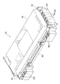
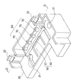
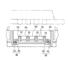
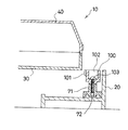
図1は基盤ケースの平面図、図2は基盤ケースの斜視図、図3は基盤ケースの分解斜視図、図4は右のベースの分解斜視図、図5は右のベースの斜視図、図6は図5のD−D線断面図、図7はケースカバーと左のベースとの斜視図、図8は図1のC−C線断面図、図9は図1のA−A線断面図、図10は図9の状態から第一の破断部を破断してベースから基盤ケースを離脱した状態を示す断面図、図11は図1のB−B線断面図、図12は図11の状態から基盤ケースをベースから離脱した状態を示す断面図を各々示す。
(基盤ケース)
図1中、10は、基盤ケースを示すものであり、この基盤ケース10は、透明又は半透明な樹脂板を用い、又、半透明又は不透明な樹脂板に小孔を多数設けた樹脂板などを用い、全体として内部に収納したものが外部から判別可能な樹脂板によって形成されており、例えば遊技機Mとしてのスロットマシン(図示せず)の機内に、予め取り付けられた、基盤ケース10を挟んで対向して配置された左右のベース20を介して固定される。
(Explanation of drawings)
1 to 12 show an embodiment of the present invention.
1 is a plan view of the base case, FIG. 2 is a perspective view of the base case, FIG. 3 is an exploded perspective view of the base case, FIG. 4 is an exploded perspective view of the right base, and FIG. 5 is a perspective view of the right base. 6 is a cross-sectional view taken along the line DD in FIG. 5, FIG. 7 is a perspective view of the case cover and the left base, FIG. 8 is a cross-sectional view taken along the line CC in FIG. 10 is a cross-sectional view showing a state in which the first fracture portion is broken from the state of FIG. 9 and the base case is detached from the base, FIG. 11 is a cross-sectional view taken along line BB of FIG. 1, and FIG. Sectional drawing which shows the state which detached | separated the base case from the base from the state of each is shown.
(Base case)
In FIG. 1,
また、前記基盤ケース10は、制御基盤(図示せず)を収納するケース本体30と、このケース本体30に固定されてケース本体30を覆うケースカバー40とを備えている。
なお、本実施の形態の一例では、遊技機Mとしてスロットマシンを例に挙げて説明したが、基盤ケース10を用いて制御基盤が取り付けられる遊技機Mは、スロットマシンに限られず、制御基盤を必要とする遊技機、例えばパチンコ機、アレンジボール機などであってもよい。
(左右のベース)
前記左右のベース20は、いずれも取り付ける遊技機の面と平行な後面に一対のネジ挿入孔21が形成され、このネジ挿入孔21に固定具としてのネジを挿入し遊技機まで貫通ねじ込むことにより、遊技機に対して固定可能に形成されている。また、各ネジ挿入孔21は、前記基盤ケース10が左右のベース20に固定された状態では、固定された基盤ケース10によって覆われ、外部から触れることができない位置で遊技機に固定されており、基盤ケース10を、左右のベース20ごと取り外してしまうことを有効に防止している。
The
In the example of the present embodiment, the slot machine is described as an example of the gaming machine M. However, the gaming machine M to which the control base is attached using the
(Left and right base)
Each of the left and
また、右のベース20には、ケースカバー40の右の側部と対向する位置に、右のベース20から垂直に立ち上がり、ケースカバー40の右の側部に係合し、ケースカバー40を遊技機側に押しつけるための係止突起22が弾性変形可能な材料で形成されている。したがって、固定された右のベース20にケースカバー40を押しつけると、一旦、係止突起22は外側に開くが、ケースカバー40の突出した部分を過ぎると再び元の位置に戻り、ケースカバー40の突出した部分に係止し、ケースカバー40を遊技機の方向へ押しつけている状態となる。
In addition, the
前記左のベース20には、ケース本体30と係合するための一対の方形状の係合孔23が、ベース20の後面と平行に形成されている。
一方、前記右のベース20には、その後面から所定間隔を介して同一方向へ立ち上がる一対の立上がり片24と、この立上がり片24に連続するとともに、右のベース20の後面と平行であって互いに対向する方向へ曲折された一対の曲折片25とからなる断面L字状の一対の支持部26が形成されている。そして、この一対の支持部26の間には、固定部材50が挿入可能に形成されている。この固定部材50は、前記両立上がり片の間に挿入可能な長さに形成されるとともに、右のベース20の後面と、曲折片25との間に形成された隙間に挿入可能な厚みに形成されている。したがって、固定部材50は、右のベース20の後面とほぼ平行な左方向から支持部26へ挿入及び支持部26から離脱が可能に形成されている。
The
On the other hand, the
また右のベース20には、前記固定部材50が挿入された状態で離脱を防止する離脱防止部材60が形成されている。この離脱防止部材60は、固定部材50の支持部26よりも固定部材50の離脱方向へ離れた位置に形成され、右のベース20の後面に対して揺動する揺動片61と、この揺動片61の支持部26側の先端に形成され、支持部26方向へ上り傾斜する傾斜爪62とから形成されている。そして、挿入する際には、固定部材50の底面が揺動片61の後面に接触し、更に固定部材50を支持部26の方向へ移動すると、傾斜爪62に突き当たるが、揺動片61は、ベース20の後面に対して揺動可能に形成されているとともに、傾斜爪62は支持部26方向へ上り傾斜しているので、固定部材50のベース20に対する位置に変更がないことから、傾斜爪62の傾斜がなくなる程度に揺動片61を押し下げることができ、この状態で固定部材50を支持部26へ挿入することができる。
The
固定部材50の支持部26への挿入が完了すると、揺動片61を押し下げているものがなくなるために、揺動片61は、再び傾斜爪62が上り傾斜となる元位置に戻る。傾斜爪62が元位置に戻ると、傾斜爪62の支持部26の側の垂直面で、固定部材50が支持部26から離脱することを防止するようになる。なお、支持部26から固定部材50を離脱するためには、傾斜爪62の傾斜面がほぼベース20の上面と同一の面となるように、指などで揺動片61を押し下げた状態にすればよい。
When the insertion of the fixing
また、前記固定部材50には、前記ケースカバー40を固定するための固定部70が4個形成されている。
前記4個の固定部70はいずれも同一の形状をしていることから、一つの形状を説明することで、他の同じ形状の固定部70の説明を省略する。
前記固定部70には、固定部材50の後面から遊技機とは反対方向に突出する円筒状部材71が形成され、この円筒状部材71には、その軸芯から遊技機方向に開口された、ネジの固定孔72が形成されている。
(ケース本体)
前記ケース本体30は、図には詳しく説明しないが、全体として遊技機Mと接する位置とは反対側を開口した箱状をなしている。
The fixing
Since all of the four fixing
The fixed
(Case body)
Although not described in detail in the figure, the case
そして、ケース本体30は、その中央に形成された、制御基盤を収納するための基盤収納部分を有し、この基盤収納部分の上方には、ケースカバー40と開閉可能に係合するための左右一対のケース本体30の側のヒンジ部80が設けられている。
なお、前記制御基盤は、図には示さないが、入賞判定やメダルの払い出し数などの遊技に関する制御を行うための基盤であって、予め遊技に関するプログラムを記憶したROMやRAM、遊技に関する制御を行うCPUなどを備えるとともに、遊技機の表側に配置されたスイッチ(図示せず)、ランプ(図示せず)や回転リール(図示せず)などと接続されている。
The
Although not shown in the figure, the control board is a board for performing game-related control such as winning determination and the number of medals to be paid out. In addition to a CPU that performs the operation, it is connected to a switch (not shown), a lamp (not shown), a rotating reel (not shown), and the like arranged on the front side of the gaming machine.
また、ケース本体30には、ケースカバー40との固定を目的とする被接続部90が、左右に2個づつ合計で4個形成されている。
各被接続部90は、同一形状に形成されているので、一つの被接続部90を説明することで、他の被接続部90の説明を省略する。
前記被接続部90は、ケース本体30から外側に突出した連接部分と、この連接部分の先端に形成された円筒状部分とを有している。そして、前記円筒状部分の先端には、ネジをねじ込むための被接続孔91が形成されている。
In addition, the
Since each
The connected
さらに、ケース本体30は、遊技機に固定される際には、上方から覆うケースカバー40に対して、内側にはまり込み、遊技機方向又は反遊技機方向へは離脱することができないように形成されている。したがって、ケース本体30を遊技機から取り外す際には、予めケースカバー40を遊技機から取り外す必要がある。
(ケースカバー)
前記ケースカバー40は、前記ケース本体30と同様に略方形状をなし、前記ケース本体30の開口部分の全部を塞ぐ大きさに形成されている。そして、ケースカバー40がケース本体30を塞ぐように配置された状態では、ケースカバー40は、ケース本体30に対して水平方向にスライド不能に形成され、ケース本体30と対向し、かつ離反する方向にのみ移動可能に形成されている。したがって、後述するように、ケースカバー40がケース本体30を覆う状態で、ケースカバー40が遊技機に固定されると、これに伴いケース本体30も間接的に遊技機に固定されることとなる。
Further, when the
(Case cover)
The case cover 40 has a substantially rectangular shape similar to the case
また、前記ケースカバー40は、ヒンジ部80を介してケースカバー40と開閉可能に軸支されている。このヒンジ部80は、図には詳しく説明しないが、ケースカバー40側のL字状の突出部分をケース本体30の側の孔に差し込むことにより、仮止め状態となり、このヒンジ部80を介して、ケース本体30に対してケースカバー40が開放可能な状態となり、ケース本体30とケースカバー40とを固定した状態では、ケース本体30側の孔に差し込まれた突出部分が抜けないような構造となっている。
The case cover 40 is pivotally supported by the case cover 40 via a
また、ケースカバー40には、左のベース20に形成された一対の係合孔23に対応する位置に、前記係合孔23にはまり込む形状の一対の係合突起41が左側に突出するように形成されている。この一つの係合突起41を右側から差し込むことで、左のベース20にケースカバー40を簡単に固定することができる。
また、前記ケースカバー40には、その右側に、前記ケースカバー40を左右のベース20に固定するための4個の取付部100が所定間隔を隔てて、ケースカバー40から突出するように設けられている。
In addition, the case cover 40 has a pair of engaging
Further, on the right side of the
前記4つの取付部100はいずれも同一の構造を有していることから、一つの取付部100を説明し、他の取付部100については、その説明を省略する。
前記取付部100は、前記ベース20に取り付けられたの固定部材50に各々対応して配置され、各々ケースカバー40の側面から右側に突出して設けられている。
前記取付部100は、所定の対向間隔をもってケースカバー40の側面から外側に張り出した2本の第一の破断部101と、この第一の破断部101の先端に設けられて円筒状をなす頭部カバー102とを備えている。
Since all of the four
The
The mounting
前記2本の第一の破断部101は、例えばニッパなどの簡単な工具を用いて切断可能な幅に形成されるとともに、ニッパなどの切断具の先端が挿入しやすいように、所定の対向間隔を介して配置されている。破断の方法は、いずれの方法であってもよいが、簡単に切断するためには、好ましくは、2本の第一の破断部101の間に形成された対向間隔に、切断具の先端を挿入する方法がよい。また、第一の破断部101を切断可能に形成すると、切断のため以外の外部からの圧力を受けて破損してしまうため、第一の破断部101を切断可能とするとともに工具を用いて破断する以外は容易に破断しないような構成として、前記2本の第一の破断部101で頭部カバー102を支持することとしている。
The two
この頭部カバー102には、その底部に、前記固定部70の円筒状部材71の固定孔72に対応してネジをねじ込み可能な取付孔103が形成されている。
そして、いずれかの取付部100の取付孔103にネジを差し込んで、取付孔103を通過し、対応する固定部70の固定孔72にまでねじ込んで締めることにより、ケースカバー40を右のベース20に固定することができる。
An
Then, by inserting a screw into the mounting
また、頭部カバー102は、ネジがねじ込み可能なように、ネジの頭部の外径よりも若干大きな内径を有しているが、止めネジの頭部の外径と頭部カバー102の内径との差は、例えばペンチなどの工具が挿入されない程度の差のみを有するように形成されている。したがって、ネジを、奥までねじ込んでしまうと、ペンチなどの工具でネジの頭部や鍔部を挟み込んで、強引に止めネジ60を反ねじ込み方向(反時計回り)に回転させてネジを緩めることはできない。
The
したがって、一旦、取付部100の取付孔103からネジがねじ込まれ、固定孔72まで達するように締め込まれてしまうと、ネジを緩めることができないことから、ケースカバー40を左右のベース20へ固定することができ、ケース本体30は、ケースカバー40の内側にはまり込んでいおり、ケースカバー40に対して対向するとともに、離反する方向へのみ移動可能に形成されているから、ケース本体30のみを右のベース20から離脱させることもできず、ケース本体30も、遊技機とこの遊技機に固定されるケースカバー40とに挟まれた状態で、遊技機に間接的に固定される。
Therefore, once the screw is screwed into the mounting
そして、いずれの取付部100及び固定部70を用いても、ケースカバー40を右のベース20から取り外すには、前記取付部100の2本の第一の破断部101を破断させる必要があることから、ケースカバー40を遊技機から取り外したり、ケースカバー40を開放した事実は一目瞭然である。
なお、ケースカバー40を左右のベース20から取り外してから、ケースカバー40をベース20に固定するには、第一の破断部101が未だ破断されていない、他の取付部100と、これに対応する固定部70とを用いればよい。
In any case, in order to remove the case cover 40 from the
In order to fix the case cover 40 to the base 20 after removing the case cover 40 from the left and
さらに、ケースカバー40と右のベース20との固定及び離脱を繰り返すと、第一の破断部101を破断していない取付部100がなくなるとともに、第一の破断部101の破断により取付部100が残されて、再び用いることのできない複数の固定部70のみとなってしまう。
この場合には、支持部26から固定部材50を離脱させ、新たな固定部材50を、支持部26に挿入させることで、取付部100の付いていない固定部70を用いることができ、さらに、すべての取付部100を破断してしまったケースカバー40は、新たなケースカバー40と交換することで、右のベース20への固定及び固定後の離脱が再び可能となる。
Furthermore, when the fixing and detachment of the
In this case, by removing the fixing
したがって、左のベース20はそのまま用いることができ、右のベース20についてもそのままで、簡単な作業で、固定部材50を交換するのみで再利用することができ、新たなベース20を用いることがないから、コストを削減することができ、ひいては資源の有効利用を図ることができる。
また、ケースカバー40には、ケース本体30への固定を目的とする接続部110が、前記ケース本体30の被接続部90に対応して、左右に2個づつ合計で4個形成されている。
Therefore, the
The case cover 40 is formed with a total of four connecting
各接続部110は、同一形状に形成されているので、一つの接続部110を説明することで、
他の接続部110の説明を省略する。
前記接続部110は、前記ケース本体30の被接続部90に対応して配置され、各々ケースカバー40の下面から下側に突出して設けられている。
そして、前記接続部110は、前記取付部100と同様に、所定の対向間隔をもってケースカバー40の側面から外側に張り出した2本の第二の破断部111と、この第二の破断部111の先端に設けられて円筒状をなす頭部カバー112とを備え、前記頭部カバー112の底には、ネジを差し込むための接続孔113が貫通形成されている。
Since each connecting
The description of the
The connecting
And, like the mounting
なお、この接続部110は、先に説明した取付部100と同一の構造を有しているので、その説明を省略する。
また、この接続部110と被接続部90との関係は、先に説明した、前記取付部100と前記固定部70との関係と同様であることから、開放した痕跡を残すことなく、ケース本体30に対してケースカバー40を開放することは困難なように形成されている。
Since the connecting
Further, since the relationship between the connecting
つぎに、上記構成を備えた基盤ケース10を遊技機に固定する方法について簡単に説明する。
まず、左右のベース20を、その対向間隔が基盤ケース10の幅に等しくなるように、遊技機に固定する。
前記左右のベース20を遊技機に固定するには、ネジ挿入孔21からネジを挿入し遊技機に貫通させるまでねじ込む。
Next, a method for fixing the
First, the left and
In order to fix the left and
そして、固定された右のベース20の支持部26に、固定部材50を挿入する。前記固定部材50の挿入は、右方向へスライドさせるように固定部材50を移動させ、固定部材50の底面で、揺動片61を、遊技機方向へ押し下げて傾斜爪62が遊技機方向へ移動するようにしながら、更にスライドさせる。前記固定部材50を、ある程度スライドさせると、傾斜爪62が固定部材50の底面から外れて、元位置に戻る。傾斜爪62が固定部材50の側面に当接した状態で、固定部材50が固定される。
Then, the fixing
一方、ケース本体30に基盤などを収納した状態で、ヒンジ部80で接続されたケースカバー40を閉じ、ケース本体30の被接続部90を、ケースカバー40の接続部110に対応させる。
前記接続部110と前記被接続部90とを対応させて、接続部110の接続孔113からネジを差し込み、被接続部90の被接続孔91までねじ込むことにより、ケース本体30にケースカバー40が固定される。通常は、右側及び左側の一対の被接続部90と接続部110とをネジを用いて固定することにより、ケース本体30にケースカバー40を固定することができ、基盤ケース10が一体化する。この状態からケースカバー40を開放するためには、二つの被接続部90と接続部110とによる固定を、一対の第二の破断部111を破断する方法のみが可能である。このため、接続部110と被接続部90とは、互いに4個形成されているので、被接続部90と接続部110とを1回固定した後に、一対の第二の破断部111を破断することにより、ケースカバー40を開放した場合には、更に1回に限り、ケース本体30とケースカバー40とを、用いていない2つの接続部110と被接続部90とを用いて、再び固定することができる。また、接続部110には、前記取付部100と同様に、頭部カバー112が形成されているので、ねじ込んだネジを緩める方向に回すことは困難である。
On the other hand, the case cover 40 connected by the
The case cover 40 is attached to the
ケース本体30とケースカバー40とが固定され、基盤ケース10が一体化した状態で、遊技機に固定された左右のベース20の間に、基盤ケース10を固定する。
まず、ケースカバー40に形成された一対の係合突起41を、左のベース20の一対の係合孔23にそれぞれ差し込む。一対の係合突起41を差し込んだ状態では、基盤ケース10は、左のベース20よりも左方向への移動が阻止され、また、そのまま、反遊技機方向への移動も阻止された状態となる。
With the
First, the pair of engaging
つぎに、ケース本体30の右側を、右側のベース20に合わせ、ベース20の固定部70と、ケースカバー40の取付部100とを対応させる。
そして、いずれかの取付部100と、それに対応する固定部70を用いて、ベース20のケースカバー40を固定する。
ケース本体30は、ケースカバー40にはまり込んだ状態では、ケースカバー40から離脱することができないから、ケース本体30の内部に収納された基盤などに触れることもできない。
Next, the right side of the
Then, the case cover 40 of the
Since the case
また、ケースカバー40を開放するためには、ケースカバー40の取付部100のうち、固定に用いている取付部100の第一の破断部101を破断しない限り、ケース本体30の内部に収納された基盤を取り出すことができない。したがって、接続部110の第一の破断部101を破断することで、ケースカバー40とケース本体30との接続を解消しても、ケースカバー40を開放することはできない。
Further, in order to open the
また、ケースカバー40を一端開放した後でも、固定に用いていない取付部100と固定部70とを用いて、再び基盤ケース10を左右のベース20を介して遊技機に固定することができる。さらには、取付部100及び固定部70の全てを使用してしまった場合には、取付部100は、基盤ケース10のうちケースカバー40のみを新たなものに交換することで、固定部70は、固定部材50を交換することで、左右のベース20を遊技機に固定したままで、再び基盤ケース10を再固定することができる。
Further, even after the case cover 40 is opened at one end, the
10 基盤ケース
20 ベース
21 ネジ挿入孔
22 係止突起
23 係合孔
24 立ち上がり片
25 曲折片
26 支持部
30 ケース本体
40 ケースカバー
41 係合突起
50 固定部材
60 離脱防止部材
61 揺動片
62 傾斜爪
70 固定部
71 円筒状部材
72 固定孔
80 ヒンジ部
90 被接続部
91 被接続孔
100 取付部
101 第一の破断部
102 頭部カバー
103 取付孔
110 接続部
111 第二の破断部
112 頭部カバー
113 接続孔
10 Base case
20 base
21 Screw insertion hole
22 Locking protrusion
23 Engagement hole
24 Rising piece
25 bent pieces
26 Support section
30 Case body
40 Case cover
41 Engagement protrusion
50 Fixed member
60 Detachment prevention member
61 Oscillating piece
62 Inclined claw
70 Fixed part
71 Cylindrical member
72 fixing hole
80 Hinge
90 Connected part
91 Connected hole
100 Mounting part
101 First fracture
102 Head cover
103 Mounting hole
110 connections
111 Second fracture
112 Head cover
113 Connection hole
Claims (1)
前記基盤ケースを遊技機に固定するためのベースと、を備えた遊技機であって、
前記基盤ケースは、
遊技機に固定されるケース本体と、
前記ケース本体を覆うように、ケース本体に固定され、固定部材を介して遊技機に対して固定されるケースカバーとを備え、
前記ケースカバーには、
ケースカバーから張り出した第一の破断部を介して、ケースカバーを前記ベースに取り付けるための複数の取付部を有し、
前記固定部材は、基盤ケースの遊技機への固定前の状態で前記ベースに対してスライド方向からの着脱を可能に形成されるとともに、前記固定部材には、前記複数の取付部に対応して、各取付部に各々固定可能な複数の固定部を有し、
前記取付部の少なくとも一つは、該取付部に対応する前記固定部とによって前記ベースを介して遊技機に取り付けられ、
基盤ケースを遊技機に取り付けるに際し、取付に用いていない取付部を次回以降の固定に使用できるようにし、
前記ケースカバーには、その一側に、取付部が形成され、この取付部が形成されていない他側に、前記ベースに形成された係合孔にはまり込むために、外方に突出した係合突起が形成され、
前記ベースには、
前記ケースカバーの反係合突起側に形成され、前記ケースカバーを前記ベースに取り付ける際には、反ケースカバー方向へ弾性変形するとともに、前記ケースカバーを前記ベースに取り付けた状態では、前記弾性変形を復元することにより、前記ケースカバーを前記ベースへ押しつけて前記ケースカバーが前記ベースから離脱するのを阻止する係止突起と、を備えたことを特徴とする遊技機。 A base case that houses a control base for controlling the gaming machine and is attached to the gaming machine;
A gaming machine comprising a base for fixing the base case to the gaming machine,
The base case is
A case body fixed to the gaming machine;
A case cover fixed to the case main body and fixed to the gaming machine via a fixing member so as to cover the case main body,
In the case cover,
A plurality of attachment portions for attaching the case cover to the base via the first fracture portion projecting from the case cover;
The fixing member is formed to be attachable to and detachable from the base in a state before the base case is fixed to the gaming machine, and the fixing member corresponds to the plurality of attachment portions. , Having a plurality of fixing portions that can be fixed to each mounting portion,
At least one of the attachment parts is attached to the gaming machine via the base by the fixing part corresponding to the attachment part,
When attaching the base case to the gaming machine, the mounting part that is not used for mounting can be used for the next and subsequent fixing,
The case cover has a mounting portion formed on one side thereof, and the other side on which the mounting portion is not formed has an engaging protrusion projecting outward in order to fit into the engagement hole formed in the base. A mating protrusion is formed,
The base includes
When the case cover is attached to the base, it is elastically deformed in the anti-case cover direction, and when the case cover is attached to the base, the elastic deformation is formed on the anti-engagement protrusion side of the case cover. A game machine comprising: a locking projection that presses the case cover against the base to prevent the case cover from being detached from the base by restoring
Priority Applications (1)
| Application Number | Priority Date | Filing Date | Title |
|---|---|---|---|
| JP2006053932A JP4395139B2 (en) | 2006-02-28 | 2006-02-28 | Game machine |
Applications Claiming Priority (1)
| Application Number | Priority Date | Filing Date | Title |
|---|---|---|---|
| JP2006053932A JP4395139B2 (en) | 2006-02-28 | 2006-02-28 | Game machine |
Related Parent Applications (1)
| Application Number | Title | Priority Date | Filing Date |
|---|---|---|---|
| JP16827099A Division JP4316051B2 (en) | 1999-06-15 | 1999-06-15 | Base case for gaming machines |
Related Child Applications (8)
| Application Number | Title | Priority Date | Filing Date |
|---|---|---|---|
| JP2009173484A Division JP4448894B2 (en) | 2009-07-24 | 2009-07-24 | Base case for gaming machines |
| JP2009173485A Division JP2009254848A (en) | 2009-07-24 | 2009-07-24 | Board case for game machine |
| JP2009173487A Division JP2009254850A (en) | 2009-07-24 | 2009-07-24 | Board case for game machine |
| JP2009173480A Division JP2009291627A (en) | 2009-07-24 | 2009-07-24 | Board case for game machine |
| JP2009173481A Division JP4521733B2 (en) | 2009-07-24 | 2009-07-24 | Base case for gaming machines |
| JP2009173483A Division JP4448893B2 (en) | 2009-07-24 | 2009-07-24 | Base case for gaming machines |
| JP2009173486A Division JP2009254849A (en) | 2009-07-24 | 2009-07-24 | Board case for game machine |
| JP2009173482A Division JP4448892B2 (en) | 2009-07-24 | 2009-07-24 | Base case for gaming machines |
Publications (3)
| Publication Number | Publication Date |
|---|---|
| JP2006142093A JP2006142093A (en) | 2006-06-08 |
| JP2006142093A5 JP2006142093A5 (en) | 2006-07-20 |
| JP4395139B2 true JP4395139B2 (en) | 2010-01-06 |
Family
ID=36622376
Family Applications (1)
| Application Number | Title | Priority Date | Filing Date |
|---|---|---|---|
| JP2006053932A Expired - Fee Related JP4395139B2 (en) | 2006-02-28 | 2006-02-28 | Game machine |
Country Status (1)
| Country | Link |
|---|---|
| JP (1) | JP4395139B2 (en) |
Cited By (1)
| Publication number | Priority date | Publication date | Assignee | Title |
|---|---|---|---|---|
| JP2009285466A (en) * | 2009-07-24 | 2009-12-10 | Sammy Corp | Board case for game machine |
Families Citing this family (3)
| Publication number | Priority date | Publication date | Assignee | Title |
|---|---|---|---|---|
| JP4964738B2 (en) * | 2007-10-26 | 2012-07-04 | 株式会社ソフイア | Game machine |
| JP4964751B2 (en) * | 2007-11-28 | 2012-07-04 | 株式会社ソフイア | Game machine |
| JP5256559B2 (en) * | 2009-02-05 | 2013-08-07 | 株式会社大都技研 | Amusement stand |
-
2006
- 2006-02-28 JP JP2006053932A patent/JP4395139B2/en not_active Expired - Fee Related
Cited By (2)
| Publication number | Priority date | Publication date | Assignee | Title |
|---|---|---|---|---|
| JP2009285466A (en) * | 2009-07-24 | 2009-12-10 | Sammy Corp | Board case for game machine |
| JP4521733B2 (en) * | 2009-07-24 | 2010-08-11 | サミー株式会社 | Base case for gaming machines |
Also Published As
| Publication number | Publication date |
|---|---|
| JP2006142093A (en) | 2006-06-08 |
Similar Documents
| Publication | Publication Date | Title |
|---|---|---|
| JP4316051B2 (en) | Base case for gaming machines | |
| JP2000354673A5 (en) | ||
| JP6078742B2 (en) | Caulking structure | |
| JP4395139B2 (en) | Game machine | |
| JP2006142093A5 (en) | ||
| JP6043907B2 (en) | Game machine | |
| JP4480652B2 (en) | Control board sealing structure | |
| JP4448893B2 (en) | Base case for gaming machines | |
| JP4448892B2 (en) | Base case for gaming machines | |
| JP4521733B2 (en) | Base case for gaming machines | |
| JP4448894B2 (en) | Base case for gaming machines | |
| JP2006142064A5 (en) | ||
| JP2009254850A (en) | Board case for game machine | |
| JP2009291627A (en) | Board case for game machine | |
| JP2009254849A (en) | Board case for game machine | |
| JP2009254848A (en) | Board case for game machine | |
| JP2009082582A (en) | Board case for game machine | |
| JP5240734B2 (en) | Case sealing structure | |
| JP3701438B2 (en) | Base case for gaming machines | |
| JP2007160004A (en) | Controller for game machine | |
| JP5057559B2 (en) | Board case | |
| JP5728691B2 (en) | Seal structure | |
| JPH11226220A (en) | Circuit board case for game machine | |
| JP2008036339A (en) | Board case of game machine | |
| JP4688181B2 (en) | Base case for gaming machines |
Legal Events
| Date | Code | Title | Description |
|---|---|---|---|
| A521 | Written amendment |
Free format text: JAPANESE INTERMEDIATE CODE: A523 Effective date: 20060425 |
|
| A621 | Written request for application examination |
Free format text: JAPANESE INTERMEDIATE CODE: A621 Effective date: 20060601 |
|
| A131 | Notification of reasons for refusal |
Free format text: JAPANESE INTERMEDIATE CODE: A131 Effective date: 20081218 |
|
| A521 | Written amendment |
Free format text: JAPANESE INTERMEDIATE CODE: A523 Effective date: 20090216 |
|
| A02 | Decision of refusal |
Free format text: JAPANESE INTERMEDIATE CODE: A02 Effective date: 20090514 |
|
| A521 | Written amendment |
Free format text: JAPANESE INTERMEDIATE CODE: A523 Effective date: 20090724 |
|
| A911 | Transfer of reconsideration by examiner before appeal (zenchi) |
Free format text: JAPANESE INTERMEDIATE CODE: A911 Effective date: 20090821 |
|
| TRDD | Decision of grant or rejection written | ||
| A01 | Written decision to grant a patent or to grant a registration (utility model) |
Free format text: JAPANESE INTERMEDIATE CODE: A01 Effective date: 20090917 |
|
| A01 | Written decision to grant a patent or to grant a registration (utility model) |
Free format text: JAPANESE INTERMEDIATE CODE: A01 |
|
| A61 | First payment of annual fees (during grant procedure) |
Free format text: JAPANESE INTERMEDIATE CODE: A61 Effective date: 20091016 |
|
| R150 | Certificate of patent or registration of utility model |
Free format text: JAPANESE INTERMEDIATE CODE: R150 |
|
| FPAY | Renewal fee payment (event date is renewal date of database) |
Free format text: PAYMENT UNTIL: 20121023 Year of fee payment: 3 |
|
| FPAY | Renewal fee payment (event date is renewal date of database) |
Free format text: PAYMENT UNTIL: 20121023 Year of fee payment: 3 |
|
| FPAY | Renewal fee payment (event date is renewal date of database) |
Free format text: PAYMENT UNTIL: 20131023 Year of fee payment: 4 |
|
| FPAY | Renewal fee payment (event date is renewal date of database) |
Free format text: PAYMENT UNTIL: 20131023 Year of fee payment: 4 |
|
| R250 | Receipt of annual fees |
Free format text: JAPANESE INTERMEDIATE CODE: R250 |
|
| R250 | Receipt of annual fees |
Free format text: JAPANESE INTERMEDIATE CODE: R250 |
|
| R250 | Receipt of annual fees |
Free format text: JAPANESE INTERMEDIATE CODE: R250 |
|
| R250 | Receipt of annual fees |
Free format text: JAPANESE INTERMEDIATE CODE: R250 |
|
| R250 | Receipt of annual fees |
Free format text: JAPANESE INTERMEDIATE CODE: R250 |
|
| LAPS | Cancellation because of no payment of annual fees |